EP3026189A1 - A tubular skylight, an accessory and a method of mounting an accessory in a tubular skylight - Google Patents
A tubular skylight, an accessory and a method of mounting an accessory in a tubular skylight Download PDFInfo
- Publication number
- EP3026189A1 EP3026189A1 EP15196287.5A EP15196287A EP3026189A1 EP 3026189 A1 EP3026189 A1 EP 3026189A1 EP 15196287 A EP15196287 A EP 15196287A EP 3026189 A1 EP3026189 A1 EP 3026189A1
- Authority
- EP
- European Patent Office
- Prior art keywords
- accessory
- tube
- ceiling
- ceiling mounted
- holding means
- Prior art date
- Legal status (The legal status is an assumption and is not a legal conclusion. Google has not performed a legal analysis and makes no representation as to the accuracy of the status listed.)
- Granted
Links
Images




Classifications
-
- E—FIXED CONSTRUCTIONS
- E04—BUILDING
- E04D—ROOF COVERINGS; SKY-LIGHTS; GUTTERS; ROOF-WORKING TOOLS
- E04D13/00—Special arrangements or devices in connection with roof coverings; Protection against birds; Roof drainage ; Sky-lights
- E04D13/03—Sky-lights; Domes; Ventilating sky-lights
-
- E—FIXED CONSTRUCTIONS
- E04—BUILDING
- E04D—ROOF COVERINGS; SKY-LIGHTS; GUTTERS; ROOF-WORKING TOOLS
- E04D13/00—Special arrangements or devices in connection with roof coverings; Protection against birds; Roof drainage ; Sky-lights
- E04D13/03—Sky-lights; Domes; Ventilating sky-lights
- E04D2013/034—Daylight conveying tubular skylights
- E04D2013/0345—Daylight conveying tubular skylights with skylight shafts extending from roof to ceiling
Definitions
- the current invention relates to a tubular skylight comprising a roof mounted element, a ceiling mounted element, a tube connecting the roof mounted element and the ceiling mounted element and a diffuser element mounted in the ceiling mounted element.
- the current invention relates to an accessory suitable for mounting in a tubular skylight.
- the current invention relates to a method of mounting, in a tubular skylight, an accessory.
- Tubular skylights of the type described above provides a path through the roof and ceiling insulation that heat will flow through from the inside of a building to the outside in the cold season and from the outside of the building to the inside in the warm season.
- heat flowing through the skylight may cause discomfort to the occupants of the building.
- the temperature difference may cause drafts and could require the need for additional heating or cooling inside the building to maintain the necessary level of comfort for the occupants.
- a tubular skylight comprising;
- an accessory suitable for mounting in a tubular skylight according to the invention wherein the accessory comprises;
- the installation of the accessory is provided in a way that has little or no impact to the performance of the tubular skylight. This is caused by the holding means being attached to the periphery of the accessory. Therefore the part of the area of the light path through the tubular skylight occupied by the holding means is small or even non-existent.
- the roof mounted element comprises a roof adapter and a window pane.
- the roof adapter is mounted in the roof of a building and serves to secure the window pane and one end of the tube in position.
- the ceiling mounted element comprises a ceiling ring to be mounted in the ceiling structure of the building.
- the ceiling ring is preferably circular or square. In alternative embodiments the ceiling ring could be elliptical, oval or polygonal or any combination thereof.
- the ceiling ring is an adapter in which the diffuser element and the other end of the tube is installed and securely held in position.
- the ceiling ring has a bore with an inscribed diameter.
- the tube is positioned between the roof mounted element and the ceiling mounted element.
- the internal surface of the tube could preferably be made of a reflective material.
- the accessory could be mounted in the tube.
- the bore of the tube could be smaller or larger than the bore of the ceiling mounted element.
- the bore of the tube has an inscribed diameter.
- the first inscribed diameter defines the size of the largest object with an orientation normal to a longitudinal axis through the bores that will pass through the bore of the ceiling mounted element and the bore of the tube.
- the accessory could be mounted in the bore of the ceiling mounted element or more specifically the ceiling ring or the tube.
- the diffuser element serves to diffuse the light entering the room from the tubular skylight.
- the diffuser element comprises a window pane that is made of a translucent material.
- the diffuser element could be removably attached to the ceiling ring.
- the accessory comprises a first element and a holding means.
- the holding means comprises a resilient element. Therefore the circumscribed diameter of the accessory may vary as the resilient element is compressed or expanded.
- the first element is a rigid disc or ring shaped element.
- the resilient element of the holding means is an annular element.
- the resilient element of the holding means comprises a plurality of discrete elements.
- the holding means further comprises a sealing element for sealing against the ceiling mounted element and/or the tube.
- the holding function and the sealing function are separated into two separate elements. This is in contrast to embodiments where the holding functions and the sealing functions are combined into one and the same element, for example, an embodiment with a single annular resilient element which tightly abuts the inside surface of the tube and/or ceiling mounted element.
- the disc or ring shaped element has shape selected among the following: circular, elliptical, oval and polygonal or a combination of the aforementioned shapes.
- polygonal shapes that could be selected are triangular, square, pentagonal, hexagonal, heptagonal, octagonal, nonagonal and decagonal.
- the accessory and the bore of the ceiling ring and/or tube has corresponding shapes, for example square or circular.
- the accessory could be made to seal tightly against the inner surface of the bore of the ceiling ring and/or the tube.
- air flowing between the volumes on either side of the accessory is limited or prevented.
- the accessory is configured for being mounted in the ceiling mounted element and/or the tube by adapting its shape and circumscribed diameter to enable the accessory to pass through the bore of the ceiling mounted element.
- the accessory could be configured for being mounted only in the ceiling mounted element or only in the tube.
- the accessory is configured for being mountable in both the ceiling mounted element and the tube.
- the same accessory could be mounted in the ceiling mounted element in some installations and in the tube in other installations.
- the accessory could be adapted for, during installation through the ceiling mounted element, being in a horizontal- or vertical orientation or any intermediate orientation between horizontal and vertical.
- the orientation as the accessory is installed should be considered during design of the ceiling mounted element, the tube and the accessory.
- the accessory can have different applications.
- the accessory can be configured as;
- the holding means has a funnel shaped extension with a reflective surface.
- the funnel shaped extension extends above the accessory when installed in the tubular skylight.
- An embodiment of the tubular skylight according to the invention is further distinguished in that the ceiling mounted element or tube comprises a shelf having a support surface, wherein the support surface has a maximum extent with a second inscribed diameter, wherein the first inscribed diameter is smaller than the second inscribed diameter, wherein the minimum extension of the support surface is equal to or larger than the first inscribed diameter, and wherein the holding means is configured for resting on the support surface.
- the accessory can be easily installed in the tubular skylight and that the correct positioning of the accessory is easy to achieve, as the position is defined by the shelf.
- shelf defines a device that bears the weight of another thing.
- the shelf can therefore support a load having a vertical component, i.e. the force of gravity.
- the support surface of the shelf could be horizontal in the installed orientation of the tubular skylight or angled up to a close to vertical orientation as long as the support surface is able to support the weight of the accessory and maintain the accessory in its intended positon within the ceiling mounted element or the tube.
- the support surface of the shelf is provided by an area that is bounded by, as a minimum, the first inscribed diameter and, as a maximum, the second inscribed diameter.
- the holding means is configured for resting on the support surface by having at least part of its structure overlapping the support surface, when the accessory is positioned on the shelf.
- the shelf is a separate element that is inserted and fastened to the ceiling mounted element or the tube.
- the inscribed diameter of the shelf is used when comparing the bore of the ceiling ring and the bore of the tube to find the first inscribed diameter. If the inscribed diameter of the shelf is smaller than the bore of the ceiling ring or the bore of the tube the inscribed diameter of the shelf becomes the first inscribed diameter.
- An embodiment of the tubular skylight according to the invention is further distinguished in that the holding means is configured for applying a normal force on the inner surface of the bore or tube and thereby retaining the accessory in the tube via friction.
- the accessory can be installed in various positions within the tubular skylight provided that the difference between the first inscribed diameter and the circumscribed diameter of the accessory is sufficiently small for the resilient element to apply a normal force of a sufficient magnitude for the accessory to stay in position.
- the position of the focal point of the lens can be adjusted by the positioning of the accessory within the tubular skylight and thereby changing the functioning and performance of the accessory.
- the holding means could be configured to expand upon insertion of the accessory into the ceiling element or the tube and thereby apply the normal force on the inner surface of the bore or tube.
- the magnitude of the normal force required to hold the accessory in position is governed by the combined friction coefficient of the holding means and the inner surface of the bore or tube.
- An embodiment of the tubular skylight according to the invention is further distinguished in that the holding means are formed such that the circumscribed diameter of the accessory is larger than the first inscribed diameter, and wherein said holding means comprises a resilient element.
- the holding means will adapt to the size and shape of the first inscribed diameter as they are inserted in the ceiling mounted element and/or the tube and then apply a normal force, or expand to its relaxed size after passing a restriction.
- the resilient element applies a normal force to the inner surface of the bore or tube.
- the resilience of the resilient element could be so chosen that the resilient is able to hold the accessory in place by friction.
- the circumscribed diameter of the accessory will increase as the resilient element expands when the accessory is aligned with the shelf.
- the accessory is hereafter supported on the shelf.
- the accessory could be configured with a resilient element that is able to be retracted or be compressed to assume the size and shape of the first inscribed diameter. Thus, it is possible to remove the accessory from the skylight.
- the resilient element is a flange protruding from the periphery of the accessory.
- the resilient element could be formed from an elastomer providing elastic properties.
- the resilient element could be made of a thermoplastic elastomer.
- a thermoplastic polymer By choosing a thermoplastic polymer there is provided a material for the resilient element which is easy to process.
- the entire holding means could be co-injection moulded with a thermoplastic elastomer injected at the resilient element and a thermoplastic polymer having different properties for the remainder of the holding means, i.e. being rigid.
- thermoplastic elastomers examples include TPE-O (olefinic), TPE-S (styrenic) or TPU (urethane).
- An embodiment of the tubular skylight according to the invention is further distinguished in that the accessory comprises a removal means for removing the accessory from the ceiling mounted element and/or tube, wherein the removal means is configured for being accessible from the ceiling side of the tubular skylight.
- the removal means should enable a user to remove the accessory from the tubular skylight in a way that prevents the accessory or the tubular skylight from being damaged.
- the removal means is a means for compressing the resilient element, such that the circumscribed diameter of the accessory becomes smaller that the first inscribed diameter.
- the removal means is a means that enables the user to grip directly by hand the removal means and pull the accessory from the tubular skylight.
- the removal means is a means that enable the user to attach a tool that enables pulling the accessory from the tubular skylight.
- the removal means could be attached to the holding means.
- the removal means could comprise a handle.
- the handle is designed especially to be grasped by the hand, for example in a primate grip.
- An embodiment of the tubular skylight according to the invention is further distinguished in that the holding means comprises a first retaining means configured for retaining said first element.
- the first disc shaped element is held in position by the holding means.
- An embodiment of the tubular skylight according to the invention is further distinguished in that the accessory comprises at least one additional element, wherein said at least one additional disc shaped element is coaxial with the first disc shaped element and wherein the holding means comprises additional disc retaining means for retaining said at least one additional element.
- the first disc retaining means and the additional disc retaining means could be spaced such that the disc shaped elements are located in the accessory with an interspace between adjacent disc shaped elements.
- the U-value is a measure of heat transmission through a building part, with lower numbers indicating better insulating properties.
- the U-value of the accessory could be further decreased by adding additional disc shaped elements.
- the first disc shaped element and the additional disc shaped elements could be provided in identical materials in one embodiment or in different materials in other embodiments.
- Fig. 1 illustrates a tubular skylight 100.
- the tubular skylight 100 comprises a roof mounted element 200, a ceiling mounted element 300 and a tube 400 connecting the roof mounted element 200 and the ceiling mounted element 300.
- the roof mounted element 200 is attached to the roof structure 10 of a building and the ceiling mounted element 300 is attached to the ceiling structure 20 of a room (not shown) in the building in which the tubular skylight 100 is installed.
- the skilled person will be able to choose among many methods of connecting the individual elements and the respective structure.
- the light continues through the tube 400 and exits the tubular skylight 100 through the ceiling mounted element 300 that is equipped with a diffuser element 340, see fig. 2, 3 , 5 and 6 .
- the light enters the room below the ceiling 20.
- vapour barrier 30 is attached to the tube 400 and to the building vapour barrier such that the vapour barrier remains unbroken even after the installation of the tubular skylight 100.
- vapour barrier 30 is also attached to the ceiling mounted element 300.
- the vapour barrier 30 may be attached only to the ceiling mounted element 300 or only to the tube 400.
- the vapour barrier 30 may be completely or partly covered with a layer of insulating material 40.
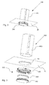
- Fig. 2 and 3 shows the tubular skylight 100 of fig. 1 in a three dimensional view and an exploded view, respectively. More specifically, fig. 2 and 3 shows the tube 400 and the ceiling mounted element 300 with its main constituents.
- the ceiling mounted element 300 comprises a ceiling ring 320 and a diffuser element 340.
- the ceiling mounted element further comprises an accessory 500.
- the ceiling ring 320 is attached to the ceiling structure 20.
- the tube 400 is positioned such that it is coaxial with the ceiling ring 320.
- the tube 400 is secured to the ceiling ring 320 by a press fit into a recess in the ceiling ring 320.
- suitable attachment means may be, for example; screws, nuts and bolts, rivets, hose clamps, snap hooks, wedges or a wedge ring etc.
- the diffuser element 340 is removably attached to the ceiling ring 320.
- the diffuser element 340 serves to diffuse the light entering the room from the tubular skylight 100.
- the accessory 500 is installed in the ceiling mounted element 300, more specifically the ceiling ring 320, see fig. 10 .
- the accessory 500 may be;
- Fig. 4 shows a ceiling ring 320 and fig. 5 shows a diffuser element 340 that is removably attachable to the ceiling ring 320.
- Fig. 6 shows an exploded view of the diffuser element 340 of fig. 5 .
- the diffuser element 340 comprises a first diffuser pane 341 and a second diffuser pane 345.
- the first diffuser pane 341 comprises a bottom portion 342 and a sidewall portion 343.
- the bottom portion 342 is planar, i.e. the width-to-height ratio is infinite.
- the bottom portion could be curved with a width-to-height ratio as low as 6.
- the bottom portion 342 is translucent
- the sidewall portion 343 and the bottom portion 342 adjoin along a transition line 347, see fig. 11 .
- the sidewall portion 343 is substantially parallel with the central axis 348 through the diffuser, see fig. 10 .
- the sidewall portion 343 has a light path zone 346.
- the light path zone 346 is more translucent than the bottom portion 342.
- the entire sidewall portion 343 is transparent.
- the translucency is not illustrated on the figures.
- the light path zone 346 in the current embodiment may be clear or transparent.
- the light path zone 346 may be engraved, or the light path zone 346 may have engraved dots or lines, or the diffuser material may, in the light path zone 346, contain light refractive or diffusing particles.
- the second diffuser pane 345 is mounted on top of the first diffuser pane 341.
- the sidewall portion 343 doubles as a spacer element.
- the spacer element provides a distance between the first diffuser pane 341 and the second diffuser pane 345.
- a closed air space is provided between the first and second diffuser pane 341, 345.
- a ledge 349 is protruding from the sidewall portion 343.
- the ledge 349 is located above the light path zone 346, so that it does not obstruct the light coming through the light path zone 346.
- the sidewall portion 343 and the ledge 349 form a circular step at the periphery of the diffuser bottom portion 342.
- the diffuser element 340 is circular.
- An external thread 350 is formed on the sidewall portion 343.
- the thread 350 is positioned above the ledge 349.
- a cooperating internal thread 308 is formed in the ceiling ring 320, see fig 4 .
- the diffuser sidewall portion 343, the bottom portion 342, the light path zone 346 and the ledge 349 and the thread 350 is translucent. However, this does not exclude other opaque components.
- the diffuser element 340 can be installed into the ceiling ring 320 by aligning the threads 308, 350 and turning the diffuser element 340 clockwise or counter clockwise dependent on the properties of the threads 308, 350.
- the diffuser element is further detailed in fig. 11 .
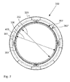
- Fig. 7 shows a top view of the ceiling mounted element 300.
- the ceiling mounted element 300 comprises a ceiling ring 320 in which the diffuser element 340 is installed, see fig. 2 and 3 .
- the ceiling mounted element 300 has a bore and the tube 400 has a bore, see fig. 11 .
- the ceiling mounted element 300 has the smaller bore of the two therefore the first inscribed diameter 302 in the present embodiment is located where the bore of the ceiling mounted element 300 is smallest.
- a shelf 304 is arranged in the ceiling mounted element for supporting the accessory 500 when it is installed in the tubular skylight 100, see fig. 3 .
- the shelf 304 has a support surface 305.
- the maximum area available for the support surface 305 is bounded by the first inscribed diameter 302 and the second inscribed diameter 306.
- the second inscribed diameter 306 has a maximum value equal to the inner diameter of the tube 400.
- the first inscribed diameter 302 and the second inscribed diameter 306 is also shown in fig. 11 .
- the support surface 305 terminates before the tube 400 leaving a free space available for the first condensate collector 360'.
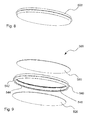
- Fig. 8 shows an accessory 500 suitable for mounting in the tubular skylight 100 of fig. 1 .
- Fig. 9 shows an exploded view of the accessory 500 of fig. 8 .
- the accessory 500 comprises a first element 520 a holding means 540 and an additional element 580.
- each of the first element 520 and the additional element 580 is a rigid disc shaped element.
- fist element 520 and/or the additional element 580 could be a ring.
- the holding means 540 comprise a resilient element 542 in the form of a flange protruding from the periphery of the accessory 500.
- the holding means 540 comprises a first retaining means 544 that retains the first element 520 and an additional retaining means 546 that retains the additional element 546 upon insertion of said first and additional elements 520, 580 into the holding means 540.
- the first element 520 and the additional element 546 is separated by an interspace. See fig. 11 for more details.
- Fig. 10 is a section view of the tubular skylight 100 near the ceiling mounted element
- fig. 11 shows detail A of fig. 10
- fig. 12 shows detail B of fig. 11 .
- Condensate develops on the internal surface 420 of the tube 400 when the internal surface 420 has a temperature below the dew point of the air inside the tube 400.
- the condensate may eventually form droplets that run down the internal surface 420 of the tube 400.
- the tubular skylight 100 comprises a first condensate collector 360' for collecting the condensate running down the internal surface 420 of the tube 400 and a second condensate collector 360" for collecting condensate running down the external surface 440 of the tube 400.
- the first condensate collector 360' has a first receptacle 361' for storing condensate and a first inlet 362' to said the first receptacle 361'. Said first inlet 362' is in communication with the internal surface 420 of the tube 400, so that condensate running down the internal surface 420 of the tube is collected by the first condensate collector 360'.
- the first inlet 362' is located in a position upstream of the diffuser element 340 such that the condensate running down the internal surface 420 of the tube 400 enters the first condensate collector 360' before it enters the diffuser element 340.
- the second condensate collector 360" comprises a second receptacle 361" for storing condensate and a second inlet 362" to said second receptacle 361". Said second inlet 362" is in communication with the external surface 440 of the tube 400. Therefore condensate running down the external surface 440 of the tube 400 is collected in the second condensate collector 360".
- Condensate running down the external surface 440 of the tube is therefore prevented from entering the diffuser element 340 or entering the ceiling structure.
- the first and second condensate collector 360', 360" is established by a groove 364 formed in the ceiling ring 320.
- the tube 400 extends into the groove 364 and divides the groove 364 into two separate elements constituting the first and second condensate collector 360', 360"
- the groove 364 has an upper end 366 in a higher position closer to the roof mounted element 200 than its lower end 368 that is in a lower position closer to the ceiling mounted element 300.
- first and second inlets 362', 362" to the first and second condensate collectors 360', 360", respectively, are located at the upper end 366 of the groove 364.
- the groove 364 has a tapered cross section.
- the upper end 366 is wider than the lower end 368 and therefore has a greater surface area.
- the groove 364 is formed with a combination of a polygonal and substantially V-shaped cross section.
- One leg of the V is longer than the other, namely the leg that, together with the tube, forms the second condensate collector 360".
- cross section may be U-shaped (not shown).
- each condensate collector 360', 360" will evaporate when the temperature and moisture conditions in the environment in the vicinity of the tubular skylight 100 so allows. Therefore the level of condensate in the condensate collectors 360', 360" will vary over time.
- the skilled person will be able to size the groove 364 and the respective condensate collectors 360', 360", such that it will be capable to hold the necessary amount of condensate.
- the tube 400 extends into the groove 364.
- the tube 400 is supported on the bottom of the groove 364.
- the tube end does not seal tightly against the bottom of the groove 364. Therefore the first and second receptacle 361', 361" are fluidly connected.
- the condensate level in each receptacle 361', 361" is therefore substantially even.
- the groove 364 is an annular groove that is formed in the ceiling mounted element 300, more specifically in the ceiling ring 320, see fig. 7 .
- the accessory 500 is installed in the ceiling mounted element 300.
- the ceiling mounted element 300 comprises a shelf 304.
- the shelf 304 has a support surface 305, see fig. 7 .
- the accessory 500 is resting on the support surface 305.
- the support surface 305 is bounded on one side by the first inscribed diameter 302.
- the support surface 305 terminates before the tube 400 leaving a free space available for the first condensate collector 360', more specifically the first inlet 362', see fig. 12 .
- the flange of the resilient element 542 is protruding from the holding means 540 in its relaxed state.
- the circumscribed diameter 502 of the accessory 500 including the resilient element 542 is larger than the first inscribed diameter 302. Therefore the resilient element 542 in its relaxed state overlaps the support surface 305, such that accessory is supported on the shelf 304.
- the resilient element 542 is compressed as is passes through the ceiling ring 320 because the ceiling ring 320 has a first inscribed diameter 302 that is smaller than the circumscribed diameter 502 of the accessory 500. As the accessory 500 is inserted further the resilient element 542 becomes free of the ceiling ring 320. The resilient element 542 expands to its larger relaxed state. The accessory can then be lowered until it rests on the shelf 304.
- the first and additional retaining means 544, 546 each comprises two flanges that grip the respective first and additional elements 520, 546.
- the holding means 540 is annular.
- the holding means 540 could comprise a plurality of discrete protrusions that protrude radially at the periphery of the holding means 540.
- the diffuser element 340 is installed into the ceiling ring 320.
- the diameter of the sidewall 343 substantially matches the diameter of the tube 400.
- a light passage from the light path zone 346 to the room is provided in the form of a free space 344 adjacent the light path zone 346.
- the free space 346 is outlined by the sidewall portion 343, the ledge 349 and the ceiling ring 320.
- the outline of the free space 344 in a plane extending radially from the central axis 348 is substantially square, rectangular or having a polygonal shape. In one other example the outline of the free space 344 in a plane extending radially from the central axis 348 is substantially square and has a height which corresponds to the height of the sidewall light path zone 346.
- a reflector 390 is integrated into the ceiling ring 320.
- the reflector 390 has a reflective surface 392 facing the light path zone 346 at an acute angle in relation to the central axis 348, see fig. 10 . Part of the light rays exiting the light path zone 346 strikes the reflective surface 392 of the reflector 390 and is directed towards the room.
- the reflector 390 may for example have a white reflective surface 392 which provides good reflection properties.
- the free space 344 is outlined by the sidewall portion 343, the ledge 349, the reflector 390 and in some cases also the ceiling ring 320.
- the leg of the outline defined by the reflector 390 will have an acute angle in relation to the central axis 348, see fig. 10 .
- Installation accessories 370 may be for example; a fastener clamp as shown operated by a fastener or it may be a hole with a screw secured into the ceiling.
- the ledge 349 functions similar to a trim ring.
- the ledge 349 forms a ring extending radially from the side wall portion 343 across the installation accessory 370 to the ceiling ring reflector 390.
- the ledge 349 thereby extends substantially across the free space 344.
- the second diffuser pane 345 is equipped with a seal 351 that seals against a sealing surface on the ceiling ring 320 when the diffuser element 300 is fully inserted into the ceiling ring 320.
- the free space 344 allows access for a user to grasp the diffuser element at the light path zone 346, where after the diffuser element 340 can easily be installed and also later removed with fingers by the end user.
- this is enabled by fastening means where rotation secures the diffuser element 340, such as a thread or matching teeth and slots. Easy removal and installation of the diffuser element 340 enables the end user to clean or upgrade the product with additional accessories 500, for example a light filter or a lamp.
- the general shape of the bottom portion 342 and sidewall portion 343 and the ledge 349 of the current embodiment enables the diffuser element 340 to be unitary and injection moulded.
- the bottom portion 342 and the ledge 349 may be in the same plane (not illustrated). In this alternative the light path zone 346 would be above the ledge 349.
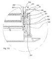
- Fig. 13 shows detail A of fig. 10 in a second embodiment of the invention where the first and second condensate collectors 360', 360" comprise a drain 380 for removing condensate from the condensate collectors 360', 360".
- the drain 380 comprises a drain pipe 384.
- the drain pipe 384 extends into the groove 364 at one end and through the vapour barrier 30 at the other end.
- the drain pipe 384 has a drain inlet 382 at the lower end 368 of the groove 364 and a drain outlet 386 on outside the vapour barrier 30.
- the drain outlet 386 is in communication with a discharge.
- the condensate is discharged through evaporation to the surroundings.
- the discharge is a pump or a heated evaporator.
- the drain pipe 384 will remove condensate from both condensate collectors 360', 360".
- first and second condensate collectors 360', 360" are separated two drain pipes may be required.
- the ceiling ring 320 has an attachment collar 321 for the vapour barrier 30.
- the attachment collar 321 is composed by the exterior wall of the second condensate collector 360".
- the exterior wall of the second condensate collector 360" is spaced from the installation accessory 370. So there is a recess between the installation accessory 370 and the exterior wall forming the attachment collar 321 where the vapour barrier 30 is inserted and fixed.
- the vapour barrier 30 may also be fixed to the tube 400.
- the vapour barrier 30 cross section is T or Y shaped so that one portion can be fixed to the tube 400 and another portion can be fixed to the attachment collar 321 and the third portion can extend across the ceiling 20.
- the attachment collar 321 is very accessible because it can be arranged such that no other component is obstructing the direct access to it. Moreover, the height of the attachment collar 321 can be increased to further improve the accessibility. In addition, in cases with a large ceiling thickness, large installation accessories are needed. By separating the installation accessories and the attachment collar by a recess, it is not necessary to extend the attachment collar up past the end of the installation accessories. In this way, a material reduction for the manufacture of the ceiling ring can be achieved.
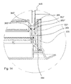
- Fig. 14 shows detail A of fig. 10 in a third embodiment of the invention.
- the tube 400 terminates above the first and second condensate collector 360', 360".
- the first and second inlets 362', 362" are the same.
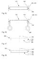
- Fig. 15 shows a schematic view of the accessory 500 in an embodiment installed in the ceiling mounted element 300 or the tube 400.
- the holding means 540 has a resilient element 542. When inserted into the ceiling mounted element 300 or the tube 400 the resilient element 542 is deformed and therefore applies a normal force on the inner surface of the bore of the ceiling mounted element 300 or the tube 400. The accessory 540 is thereby retained via friction between the resilient element 542 and the ceiling mounted element 300 or the tube 400 respectively.
- Fig. 16 shows a schematic view of the accessory 500 in an embodiment having removal means 560 in the form of handles.
- Fig. 17 shows a side view of a second embodiment of the diffuser element 340.
- the sidewall portion 343 is inclined 25° in relation to the central axis 348.
- Fig. 18 shows a side view of a third embodiment of the diffuser element 340.
- the sidewall portion 343 is inclined -10° in relation to the central axis 348.
Landscapes
- Engineering & Computer Science (AREA)
- Architecture (AREA)
- Civil Engineering (AREA)
- Structural Engineering (AREA)
- Non-Portable Lighting Devices Or Systems Thereof (AREA)
Abstract

Description
- The current invention relates to a tubular skylight comprising a roof mounted element, a ceiling mounted element, a tube connecting the roof mounted element and the ceiling mounted element and a diffuser element mounted in the ceiling mounted element.
- Moreover, the current invention relates to an accessory suitable for mounting in a tubular skylight.
- Additionally, the current invention relates to a method of mounting, in a tubular skylight, an accessory.
- Tubular skylights of the type described above provides a path through the roof and ceiling insulation that heat will flow through from the inside of a building to the outside in the cold season and from the outside of the building to the inside in the warm season. When the temperature difference between the outside and the inside of the building is above a certain threshold, heat flowing through the skylight may cause discomfort to the occupants of the building. The temperature difference may cause drafts and could require the need for additional heating or cooling inside the building to maintain the necessary level of comfort for the occupants.
- In a prior art tubular skylight this problem has been solved by adding discrete holding pieces that are attached to the interior of the tube element by adhesive tape. One or more discs of transparent material are moved past the holding pieces while the surface of the discs are oriented in vertical position. After passing the holding pieces the discs are rotated into horizontal position and positioned and supported on the holding pieces. The principle requires many parts that have to be installed correctly into the interior of the tube.
- It is an object of the present invention to provide a tubular skylight and an accessory that is easy to install in the tubular skylight.
- It is an additional object of the present invention to provide a method of mounting, in a tubular skylight, an accessory.
- According to the present invention, this is achieved by a tubular skylight comprising;
- a roof mounted element,
- a ceiling mounted element,
- a tube connecting the roof mounted element and the ceiling mounted element, wherein the ceiling mounted element and the tube has a bore, and wherein the smaller bore of the two bores defines a first inscribed diameter, and
- a diffuser element mounted in the ceiling mounted element,
- an accessory comprising;
- a first element configured for being mounted in the ceiling mounted element and/or the tube, wherein the first element is a rigid disc or ring shaped element, and
- a holding means configured for retaining the position of the accessory within the ceiling mounted element and/or tube, wherein the holding means is connected to the periphery of said first element, and that said holding means comprises a resilient element, wherein said resilient element is configured for allowing the circumscribed diameter of the accessory to vary at least between a minimum value equal to the first inscribed diameter and a maximum value exceeding the first inscribed diameter.
- Moreover, according to the present invention, this is achieved by an accessory suitable for mounting in a tubular skylight according to the invention, wherein the accessory comprises;
- a first element configured for being mounted in the ceiling mounted element and/or the tube, wherein the first element is a rigid disc or ring shaped element,
- a holding means configured for retaining the position of the accessory within the ceiling mounted element and/or tube,
- Furthermore, according to the present invention, this is achieved by a method of mounting, in a tubular skylight according to the invention an accessory comprising;
- a first element configured for being mounted in the ceiling mounted element and/or the tube, and
- a holding means configured for retaining the position of the accessory within the ceiling mounted element and/or tube, wherein the first element is a rigid disc or ring shaped element,
- It is herewith achieved that the accessory can be easily installed in the tubular skylight.
- Moreover it is achieved that the installation of the accessory is provided in a way that has little or no impact to the performance of the tubular skylight. This is caused by the holding means being attached to the periphery of the accessory. Therefore the part of the area of the light path through the tubular skylight occupied by the holding means is small or even non-existent.
- The roof mounted element comprises a roof adapter and a window pane. The roof adapter is mounted in the roof of a building and serves to secure the window pane and one end of the tube in position.
- The ceiling mounted element comprises a ceiling ring to be mounted in the ceiling structure of the building.
- The ceiling ring is preferably circular or square. In alternative embodiments the ceiling ring could be elliptical, oval or polygonal or any combination thereof.
- The ceiling ring is an adapter in which the diffuser element and the other end of the tube is installed and securely held in position.
- The ceiling ring has a bore with an inscribed diameter.
- The tube is positioned between the roof mounted element and the ceiling mounted element. The internal surface of the tube could preferably be made of a reflective material. The accessory could be mounted in the tube. The bore of the tube could be smaller or larger than the bore of the ceiling mounted element.
- The bore of the tube has an inscribed diameter.
- When comparing the two bores the smaller of the two defines the first inscribed diameter. The first inscribed diameter defines the size of the largest object with an orientation normal to a longitudinal axis through the bores that will pass through the bore of the ceiling mounted element and the bore of the tube.
- The accessory could be mounted in the bore of the ceiling mounted element or more specifically the ceiling ring or the tube.
- The diffuser element serves to diffuse the light entering the room from the tubular skylight. The diffuser element comprises a window pane that is made of a translucent material. The diffuser element could be removably attached to the ceiling ring.
- Light enters the tubular skylight through the roof mounted element and travels through the tube to the diffuser where it exits the tubular skylight.
- The accessory comprises a first element and a holding means. The holding means comprises a resilient element. Therefore the circumscribed diameter of the accessory may vary as the resilient element is compressed or expanded.
- The first element is a rigid disc or ring shaped element.
- In an embodiment of the invention the resilient element of the holding means is an annular element.
- In an embodiment of the invention the resilient element of the holding means comprises a plurality of discrete elements.
- In an embodiment of the invention the holding means further comprises a sealing element for sealing against the ceiling mounted element and/or the tube.
- With this embodiment the holding function and the sealing function are separated into two separate elements. This is in contrast to embodiments where the holding functions and the sealing functions are combined into one and the same element, for example, an embodiment with a single annular resilient element which tightly abuts the inside surface of the tube and/or ceiling mounted element.
- In an embodiment of the tubular skylight the disc or ring shaped element has shape selected among the following: circular, elliptical, oval and polygonal or a combination of the aforementioned shapes. Examples of polygonal shapes that could be selected are triangular, square, pentagonal, hexagonal, heptagonal, octagonal, nonagonal and decagonal.
- In an embodiment of the tubular skylight, the accessory and the bore of the ceiling ring and/or tube has corresponding shapes, for example square or circular.
- In this embodiment the accessory could be made to seal tightly against the inner surface of the bore of the ceiling ring and/or the tube.
- In this embodiment air flowing between the volumes on either side of the accessory is limited or prevented.
- In its relaxed state the circumscribed diameter of the accessory is larger than the first inscribed diameter.
- The accessory is configured for being mounted in the ceiling mounted element and/or the tube by adapting its shape and circumscribed diameter to enable the accessory to pass through the bore of the ceiling mounted element.
- The accessory could be configured for being mounted only in the ceiling mounted element or only in the tube.
- In an embodiment the accessory is configured for being mountable in both the ceiling mounted element and the tube. In this embodiment the same accessory could be mounted in the ceiling mounted element in some installations and in the tube in other installations.
- The accessory could be adapted for, during installation through the ceiling mounted element, being in a horizontal- or vertical orientation or any intermediate orientation between horizontal and vertical. The orientation as the accessory is installed should be considered during design of the ceiling mounted element, the tube and the accessory.
- The accessory can have different applications. For example the accessory can be configured as;
- a thermal insulator for improving the U-value of the tubular skylight,
- a filter, for affecting the properties of the light entering the diffuser element,
- a lamp, for providing light when it is dark outside the building or for adding to the light entering through the tubular skylight, or
- any other type of accessory suitable for use in a tubular skylight.
- In an embodiment the holding means has a funnel shaped extension with a reflective surface. The funnel shaped extension extends above the accessory when installed in the tubular skylight.
- It is herewith achieved that a space between the bore of the ceiling mounted element and the bore of the tube due to a difference in the shape and sizes of said two elements is covered by the funnel shaped extension and light is not thereby not lost due to said space. The same is true for any differences in shape and size between the accessory and the tube and/or ceiling mounted element.
- An embodiment of the tubular skylight according to the invention is further distinguished in that the ceiling mounted element or tube comprises a shelf having a support surface, wherein the support surface has a maximum extent with a second inscribed diameter, wherein the first inscribed diameter is smaller than the second inscribed diameter, wherein the minimum extension of the support surface is equal to or larger than the first inscribed diameter, and wherein the holding means is configured for resting on the support surface.
- It is herewith achieved that the accessory can be easily installed in the tubular skylight and that the correct positioning of the accessory is easy to achieve, as the position is defined by the shelf.
- In the present application the term "shelf" defines a device that bears the weight of another thing. The shelf can therefore support a load having a vertical component, i.e. the force of gravity.
- The support surface of the shelf could be horizontal in the installed orientation of the tubular skylight or angled up to a close to vertical orientation as long as the support surface is able to support the weight of the accessory and maintain the accessory in its intended positon within the ceiling mounted element or the tube.
- The support surface of the shelf is provided by an area that is bounded by, as a minimum, the first inscribed diameter and, as a maximum, the second inscribed diameter.
- The holding means is configured for resting on the support surface by having at least part of its structure overlapping the support surface, when the accessory is positioned on the shelf.
- In an embodiment the shelf is a separate element that is inserted and fastened to the ceiling mounted element or the tube. The inscribed diameter of the shelf is used when comparing the bore of the ceiling ring and the bore of the tube to find the first inscribed diameter. If the inscribed diameter of the shelf is smaller than the bore of the ceiling ring or the bore of the tube the inscribed diameter of the shelf becomes the first inscribed diameter.
- An embodiment of the tubular skylight according to the invention is further distinguished in that the holding means is configured for applying a normal force on the inner surface of the bore or tube and thereby retaining the accessory in the tube via friction.
- It is herewith achieved that the accessory can be installed in various positions within the tubular skylight provided that the difference between the first inscribed diameter and the circumscribed diameter of the accessory is sufficiently small for the resilient element to apply a normal force of a sufficient magnitude for the accessory to stay in position.
- Being able to change the location of the accessory within the tubular skylight could change the functioning and performance of the accessory.
- For example where the accessory comprises a lens the position of the focal point of the lens can be adjusted by the positioning of the accessory within the tubular skylight and thereby changing the functioning and performance of the accessory.
- The holding means could be configured to expand upon insertion of the accessory into the ceiling element or the tube and thereby apply the normal force on the inner surface of the bore or tube.
- The magnitude of the normal force required to hold the accessory in position is governed by the combined friction coefficient of the holding means and the inner surface of the bore or tube.
- An embodiment of the tubular skylight according to the invention is further distinguished in that the holding means are formed such that the circumscribed diameter of the accessory is larger than the first inscribed diameter, and wherein said holding means comprises a resilient element.
- It is herewith achieved that the holding means will adapt to the size and shape of the first inscribed diameter as they are inserted in the ceiling mounted element and/or the tube and then apply a normal force, or expand to its relaxed size after passing a restriction.
- The resilient element applies a normal force to the inner surface of the bore or tube. The resilience of the resilient element could be so chosen that the resilient is able to hold the accessory in place by friction.
- In an embodiment, where the ceiling mounted element or the tube comprise a shelf the circumscribed diameter of the accessory will increase as the resilient element expands when the accessory is aligned with the shelf. The accessory is hereafter supported on the shelf.
- Therefore with this embodiment it is achieved that the same accessory could be devised to be supported on a shelf or retained by friction in the skylight as described above.
- The accessory could be configured with a resilient element that is able to be retracted or be compressed to assume the size and shape of the first inscribed diameter. Thus, it is possible to remove the accessory from the skylight.
- In an embodiment, the resilient element is a flange protruding from the periphery of the accessory.
- The resilient element could be formed from an elastomer providing elastic properties.
- In an embodiment the resilient element could be made of a thermoplastic elastomer. By choosing a thermoplastic polymer there is provided a material for the resilient element which is easy to process.
- For example the entire holding means could be co-injection moulded with a thermoplastic elastomer injected at the resilient element and a thermoplastic polymer having different properties for the remainder of the holding means, i.e. being rigid.
- Examples of thermoplastic elastomers are TPE-O (olefinic), TPE-S (styrenic) or TPU (urethane).
- An embodiment of the tubular skylight according to the invention is further distinguished in that the accessory comprises a removal means for removing the accessory from the ceiling mounted element and/or tube, wherein the removal means is configured for being accessible from the ceiling side of the tubular skylight.
- It is herewith achieved that the accessory can be easily removed.
- The removal means should enable a user to remove the accessory from the tubular skylight in a way that prevents the accessory or the tubular skylight from being damaged.
- In an embodiment the removal means is a means for compressing the resilient element, such that the circumscribed diameter of the accessory becomes smaller that the first inscribed diameter.
- In another embodiment the removal means is a means that enables the user to grip directly by hand the removal means and pull the accessory from the tubular skylight.
- In yet another embodiment the removal means is a means that enable the user to attach a tool that enables pulling the accessory from the tubular skylight.
- The removal means could be attached to the holding means.
- It is herewith achieved that the forces required to remove the accessory is applied close to the location of the holding means. Therefore the first element is almost completely unaffected by the forces applied when the accessory is removed from the tubular skylight. Therefore the first element does not have to be designed to withstand these forces.
- The removal means could comprise a handle.
- The handle is designed especially to be grasped by the hand, for example in a primate grip.
- This enables the accessory to be removed without having to apply external tools.
- An embodiment of the tubular skylight according to the invention is further distinguished in that the holding means comprises a first retaining means configured for retaining said first element.
- It is herewith achieved that the first disc shaped element is held in position by the holding means.
- An embodiment of the tubular skylight according to the invention is further distinguished in that the accessory comprises at least one additional element, wherein said at least one additional disc shaped element is coaxial with the first disc shaped element and wherein the holding means comprises additional disc retaining means for retaining said at least one additional element.
- The first disc retaining means and the additional disc retaining means could be spaced such that the disc shaped elements are located in the accessory with an interspace between adjacent disc shaped elements.
- It is herewith achieved that the U-value of the accessory could be decreased dependent on the materials used. The overall U-value of the tubular skylight will benefit from this.
- The U-value is a measure of heat transmission through a building part, with lower numbers indicating better insulating properties.
- The U-value of the accessory could be further decreased by adding additional disc shaped elements.
- The first disc shaped element and the additional disc shaped elements could be provided in identical materials in one embodiment or in different materials in other embodiments.
- It should be emphasized that the term "comprises/comprising/comprised of" when used in this specification is taken to specify the presence of stated features, integers, steps or components but does not preclude the presence or addition of one or more other features, integers, steps, components or groups thereof.
- The invention will be explained in more detail below with reference to the accompanying figures, where:
- Fig. 1
- schematically illustrates a tubular skylight according to invention,
- fig. 2
- shows a three dimensional view of the tubular skylight of
fig. 1 , - fig. 3
- shows an exploded view of the tubular skylight of
fig. 1 , - fig. 4
- shows a ceiling ring,
- fig. 5
- shows a diffuser element,
- fig. 6
- shows an exploded view of the diffuser element of
fig. 5 , - fig. 7
- shows a top view of the ceiling ring,
- fig. 8
- shows an accessory suitable for mounting in the tubular skylight of
fig. 1 , - fig. 9
- shows an exploded view of the accessory of
fig. 7 , - fig. 10
- is a section view of the tubular skylight near the ceiling mounted element,
- fig. 11
- shows detail A of
fig. 10 , - fig. 12
- shows detail B of
fig. 11 , - fig. 13
- shows a view located at detail A of
fig. 10 in a second embodiment of the invention, - fig. 14
- shows a view located at detail A of
fig. 10 in a third embodiment of the invention, - fig. 15
- shows a schematic view of the accessory in an embodiment installed in the ceiling mounted element or the tube,
- fig. 16
- shows a schematic view of the accessory in an embodiment having a removal means,
- fig. 17
- shows a side view of a second embodiment of the diffuser element, and
- fig. 18
- shows a side view of a third embodiment of the diffuser element.
- It should be emphasized that the embodiments shown are used for example purposes only and should not be used to limit the scope of the invention.
- In the explanation of the figures, identical or corresponding elements will be provided with the same reference numerals in different figures. Therefore, no explanation of all details will be given in connection with each single figure/embodiment.
-
Fig. 1 illustrates atubular skylight 100. Thetubular skylight 100 comprises a roof mountedelement 200, a ceiling mountedelement 300 and atube 400 connecting the roof mountedelement 200 and the ceiling mountedelement 300. - The roof mounted
element 200 is attached to theroof structure 10 of a building and the ceiling mountedelement 300 is attached to theceiling structure 20 of a room (not shown) in the building in which thetubular skylight 100 is installed. The skilled person will be able to choose among many methods of connecting the individual elements and the respective structure. - Light enters the
tubular skylight 100 through the roof mountedelement 200 through a window pane (not shown). The light continues through thetube 400 and exits thetubular skylight 100 through the ceiling mountedelement 300 that is equipped with adiffuser element 340, seefig. 2, 3 ,5 and 6 . Hereafter the light enters the room below theceiling 20. - The building vapour barrier in the ceiling structure is penetrated by the
tubular skylight 100. In order to retain the vapour barrier effect avapour barrier 30 is attached to thetube 400 and to the building vapour barrier such that the vapour barrier remains unbroken even after the installation of thetubular skylight 100. - In the embodiment shown the
vapour barrier 30 is also attached to the ceiling mountedelement 300. - In alternative embodiments (not shown) the
vapour barrier 30 may be attached only to the ceiling mountedelement 300 or only to thetube 400. - The
vapour barrier 30 may be completely or partly covered with a layer of insulatingmaterial 40. -
Fig. 2 and 3 shows thetubular skylight 100 offig. 1 in a three dimensional view and an exploded view, respectively. More specifically,fig. 2 and 3 shows thetube 400 and the ceiling mountedelement 300 with its main constituents. - The ceiling mounted
element 300 comprises aceiling ring 320 and adiffuser element 340. - In the embodiment shown the ceiling mounted element further comprises an
accessory 500. - The
ceiling ring 320 is attached to theceiling structure 20. Thetube 400 is positioned such that it is coaxial with theceiling ring 320. Thetube 400 is secured to theceiling ring 320 by a press fit into a recess in theceiling ring 320. - Alternatively, suitable attachment means may be, for example; screws, nuts and bolts, rivets, hose clamps, snap hooks, wedges or a wedge ring etc.
- The
diffuser element 340 is removably attached to theceiling ring 320. Thediffuser element 340 serves to diffuse the light entering the room from thetubular skylight 100. - In the present embodiment the
accessory 500 is installed in the ceiling mountedelement 300, more specifically theceiling ring 320, seefig. 10 . - For example the
accessory 500 may be; - a thermal insulator, for decreasing the U-value of the
tubular skylight 100, - a filter, for affecting the properties of the light entering the
diffuser element 340, - a lamp, for providing light when it is dark outside the building or for adding to the light entering through the
tubular skylight 100, or - any other type of accessory suitable for use in a
tubular skylight 100. -
Fig. 4 shows aceiling ring 320 andfig. 5 shows adiffuser element 340 that is removably attachable to theceiling ring 320. -
Fig. 6 shows an exploded view of thediffuser element 340 offig. 5 . - The
diffuser element 340 comprises afirst diffuser pane 341 and asecond diffuser pane 345. - The
first diffuser pane 341 comprises abottom portion 342 and asidewall portion 343. - In the embodiment shown, the
bottom portion 342 is planar, i.e. the width-to-height ratio is infinite. - In alternative embodiments the bottom portion could be curved with a width-to-height ratio as low as 6.
- The
bottom portion 342 is translucent - The
sidewall portion 343 and thebottom portion 342 adjoin along atransition line 347, seefig. 11 . - The
sidewall portion 343 is substantially parallel with thecentral axis 348 through the diffuser, seefig. 10 . - The
sidewall portion 343 has alight path zone 346. Thelight path zone 346 is more translucent than thebottom portion 342. - In an embodiment the
entire sidewall portion 343 is transparent. - The translucency is not illustrated on the figures.
- To provide enhanced light outside the
bottom portion 342, thelight path zone 346 in the current embodiment may be clear or transparent. In other embodiments, thelight path zone 346 may be engraved, or thelight path zone 346 may have engraved dots or lines, or the diffuser material may, in thelight path zone 346, contain light refractive or diffusing particles. - The
second diffuser pane 345 is mounted on top of thefirst diffuser pane 341. In the embodiment shown, thesidewall portion 343 doubles as a spacer element. The spacer element provides a distance between thefirst diffuser pane 341 and thesecond diffuser pane 345. Thus, a closed air space is provided between the first andsecond diffuser pane - A
ledge 349 is protruding from thesidewall portion 343. Theledge 349 is located above thelight path zone 346, so that it does not obstruct the light coming through thelight path zone 346. - The
sidewall portion 343 and theledge 349 form a circular step at the periphery of thediffuser bottom portion 342. - In the embodiment shown the
diffuser element 340 is circular. Anexternal thread 350 is formed on thesidewall portion 343. Thethread 350 is positioned above theledge 349. A cooperatinginternal thread 308 is formed in theceiling ring 320, seefig 4 . - In one example the
diffuser sidewall portion 343, thebottom portion 342, thelight path zone 346 and theledge 349 and thethread 350 is translucent. However, this does not exclude other opaque components. - The
diffuser element 340 can be installed into theceiling ring 320 by aligning thethreads diffuser element 340 clockwise or counter clockwise dependent on the properties of thethreads - The diffuser element is further detailed in
fig. 11 . -
Fig. 7 shows a top view of the ceiling mountedelement 300. - The ceiling mounted
element 300 comprises aceiling ring 320 in which thediffuser element 340 is installed, seefig. 2 and 3 . - The ceiling mounted
element 300 has a bore and thetube 400 has a bore, seefig. 11 . The ceiling mountedelement 300 has the smaller bore of the two therefore the first inscribeddiameter 302 in the present embodiment is located where the bore of the ceiling mountedelement 300 is smallest. - A
shelf 304 is arranged in the ceiling mounted element for supporting theaccessory 500 when it is installed in thetubular skylight 100, seefig. 3 . - The
shelf 304 has asupport surface 305. The maximum area available for thesupport surface 305 is bounded by the first inscribeddiameter 302 and the second inscribeddiameter 306. In the embodiment shown the second inscribeddiameter 306 has a maximum value equal to the inner diameter of thetube 400. - The first inscribed
diameter 302 and the second inscribeddiameter 306 is also shown infig. 11 . - In the embodiment shown in
fig. 7 thesupport surface 305 terminates before thetube 400 leaving a free space available for the first condensate collector 360'. -
Fig. 8 shows anaccessory 500 suitable for mounting in thetubular skylight 100 offig. 1 .Fig. 9 shows an exploded view of theaccessory 500 offig. 8 . - In the embodiment shown, the
accessory 500 comprises a first element 520 a holding means 540 and anadditional element 580. In the embodiment shown each of thefirst element 520 and theadditional element 580 is a rigid disc shaped element. - Alternatively the
fist element 520 and/or theadditional element 580 could be a ring. - The holding means 540 comprise a
resilient element 542 in the form of a flange protruding from the periphery of theaccessory 500. - The holding means 540 comprises a first retaining means 544 that retains the
first element 520 and an additional retaining means 546 that retains theadditional element 546 upon insertion of said first andadditional elements first element 520 and theadditional element 546 is separated by an interspace. Seefig. 11 for more details. -
Fig. 10 is a section view of thetubular skylight 100 near the ceiling mounted element,fig. 11 shows detail A offig. 10 andfig. 12 shows detail B offig. 11 . - Condensate develops on the
internal surface 420 of thetube 400 when theinternal surface 420 has a temperature below the dew point of the air inside thetube 400. The condensate may eventually form droplets that run down theinternal surface 420 of thetube 400. - The
tubular skylight 100 comprises a first condensate collector 360' for collecting the condensate running down theinternal surface 420 of thetube 400 and asecond condensate collector 360" for collecting condensate running down theexternal surface 440 of thetube 400. - The first condensate collector 360' has a first receptacle 361' for storing condensate and a first inlet 362' to said the first receptacle 361'. Said first inlet 362' is in communication with the
internal surface 420 of thetube 400, so that condensate running down theinternal surface 420 of the tube is collected by the first condensate collector 360'. - The first inlet 362' is located in a position upstream of the
diffuser element 340 such that the condensate running down theinternal surface 420 of thetube 400 enters the first condensate collector 360' before it enters thediffuser element 340. - The
second condensate collector 360" comprises asecond receptacle 361" for storing condensate and asecond inlet 362" to saidsecond receptacle 361". Saidsecond inlet 362" is in communication with theexternal surface 440 of thetube 400. Therefore condensate running down theexternal surface 440 of thetube 400 is collected in thesecond condensate collector 360". - Condensate running down the
external surface 440 of the tube is therefore prevented from entering thediffuser element 340 or entering the ceiling structure. - The first and
second condensate collector 360', 360" is established by agroove 364 formed in theceiling ring 320. Thetube 400 extends into thegroove 364 and divides thegroove 364 into two separate elements constituting the first andsecond condensate collector 360', 360" - The
groove 364 has anupper end 366 in a higher position closer to the roof mountedelement 200 than itslower end 368 that is in a lower position closer to the ceiling mountedelement 300. - From
fig. 12 it appears that the first andsecond inlets 362', 362" to the first andsecond condensate collectors 360', 360", respectively, are located at theupper end 366 of thegroove 364. - The
groove 364 has a tapered cross section. Theupper end 366 is wider than thelower end 368 and therefore has a greater surface area. - The
groove 364 is formed with a combination of a polygonal and substantially V-shaped cross section. One leg of the V is longer than the other, namely the leg that, together with the tube, forms thesecond condensate collector 360". - In alternative embodiments the cross section may be U-shaped (not shown).
- In the embodiment shown in
fig. 9 ,10 and 11 thegroove 364 is closed at itslower end 368. Therefore thegroove 364 forms a reservoir for condensate. The condensate collected in eachcondensate collector 360', 360" will evaporate when the temperature and moisture conditions in the environment in the vicinity of thetubular skylight 100 so allows. Therefore the level of condensate in thecondensate collectors 360', 360" will vary over time. - Based on the environment that the
tubular skylight 100 will be subject to, the skilled person will be able to size thegroove 364 and therespective condensate collectors 360', 360", such that it will be capable to hold the necessary amount of condensate. - The
tube 400 extends into thegroove 364. Thetube 400 is supported on the bottom of thegroove 364. The tube end does not seal tightly against the bottom of thegroove 364. Therefore the first andsecond receptacle 361', 361" are fluidly connected. The condensate level in eachreceptacle 361', 361" is therefore substantially even. - The
groove 364 is an annular groove that is formed in the ceiling mountedelement 300, more specifically in theceiling ring 320, seefig. 7 . - In the embodiment shown the
accessory 500 is installed in the ceiling mountedelement 300. - The ceiling mounted
element 300 comprises ashelf 304. Theshelf 304 has asupport surface 305, seefig. 7 . Theaccessory 500 is resting on thesupport surface 305. - The
support surface 305 is bounded on one side by the first inscribeddiameter 302. Thesupport surface 305 terminates before thetube 400 leaving a free space available for the first condensate collector 360', more specifically the first inlet 362', seefig. 12 . - The flange of the
resilient element 542 is protruding from the holding means 540 in its relaxed state. The circumscribeddiameter 502 of theaccessory 500 including theresilient element 542 is larger than the first inscribeddiameter 302. Therefore theresilient element 542 in its relaxed state overlaps thesupport surface 305, such that accessory is supported on theshelf 304. - During insertion of the
accessory 500 into the ceiling mountedelement 300 theresilient element 542 is compressed as is passes through theceiling ring 320 because theceiling ring 320 has a first inscribeddiameter 302 that is smaller than the circumscribeddiameter 502 of theaccessory 500. As theaccessory 500 is inserted further theresilient element 542 becomes free of theceiling ring 320. Theresilient element 542 expands to its larger relaxed state. The accessory can then be lowered until it rests on theshelf 304. - The first and additional retaining means 544, 546 each comprises two flanges that grip the respective first and
additional elements - The holding means 540 is annular.
- Alternatively the holding means 540 could comprise a plurality of discrete protrusions that protrude radially at the periphery of the holding means 540.
- In
fig. 10, 11 and12 , thediffuser element 340 is installed into theceiling ring 320. - The diameter of the
sidewall 343 substantially matches the diameter of thetube 400. - A light passage from the
light path zone 346 to the room is provided in the form of afree space 344 adjacent thelight path zone 346. Thefree space 346 is outlined by thesidewall portion 343, theledge 349 and theceiling ring 320. - In one example the outline of the
free space 344 in a plane extending radially from thecentral axis 348 is substantially square, rectangular or having a polygonal shape. In one other example the outline of thefree space 344 in a plane extending radially from thecentral axis 348 is substantially square and has a height which corresponds to the height of the sidewalllight path zone 346. - A
reflector 390 is integrated into theceiling ring 320. Thereflector 390 has areflective surface 392 facing thelight path zone 346 at an acute angle in relation to thecentral axis 348, seefig. 10 . Part of the light rays exiting thelight path zone 346 strikes thereflective surface 392 of thereflector 390 and is directed towards the room. - The
reflector 390 may for example have a whitereflective surface 392 which provides good reflection properties. - In embodiments with a
reflector 390, thefree space 344 is outlined by thesidewall portion 343, theledge 349, thereflector 390 and in some cases also theceiling ring 320. The leg of the outline defined by thereflector 390 will have an acute angle in relation to thecentral axis 348, seefig. 10 . - In
fig. 11 it can be seen how theledge 349 covers and thereby hides theinstallation accessories 370. -
Installation accessories 370 may be for example; a fastener clamp as shown operated by a fastener or it may be a hole with a screw secured into the ceiling. - The
ledge 349 functions similar to a trim ring. Theledge 349 forms a ring extending radially from theside wall portion 343 across theinstallation accessory 370 to theceiling ring reflector 390. Theledge 349 thereby extends substantially across thefree space 344. - The
second diffuser pane 345 is equipped with aseal 351 that seals against a sealing surface on theceiling ring 320 when thediffuser element 300 is fully inserted into theceiling ring 320. - In one example the
free space 344 allows access for a user to grasp the diffuser element at thelight path zone 346, where after thediffuser element 340 can easily be installed and also later removed with fingers by the end user. Preferably, this is enabled by fastening means where rotation secures thediffuser element 340, such as a thread or matching teeth and slots. Easy removal and installation of thediffuser element 340 enables the end user to clean or upgrade the product withadditional accessories 500, for example a light filter or a lamp. - The general shape of the
bottom portion 342 andsidewall portion 343 and theledge 349 of the current embodiment enables thediffuser element 340 to be unitary and injection moulded. - In one alternative, the
bottom portion 342 and theledge 349 may be in the same plane (not illustrated). In this alternative thelight path zone 346 would be above theledge 349. -
Fig. 13 shows detail A offig. 10 in a second embodiment of the invention where the first andsecond condensate collectors 360', 360" comprise adrain 380 for removing condensate from thecondensate collectors 360', 360". - The
drain 380 comprises adrain pipe 384. Thedrain pipe 384 extends into thegroove 364 at one end and through thevapour barrier 30 at the other end. Thedrain pipe 384 has adrain inlet 382 at thelower end 368 of thegroove 364 and adrain outlet 386 on outside thevapour barrier 30. - The
drain outlet 386 is in communication with a discharge. In the embodiment shown the condensate is discharged through evaporation to the surroundings. - In alternative embodiments the discharge is a pump or a heated evaporator.
- As the first and
second condensate collectors 360', 360" are fluidly connected thedrain pipe 384 will remove condensate from bothcondensate collectors 360', 360". - In alternative embodiments where the first and
second condensate collectors 360', 360" are separated two drain pipes may be required. - The
ceiling ring 320 has anattachment collar 321 for thevapour barrier 30. Theattachment collar 321 is composed by the exterior wall of thesecond condensate collector 360". The exterior wall of thesecond condensate collector 360" is spaced from theinstallation accessory 370. So there is a recess between theinstallation accessory 370 and the exterior wall forming theattachment collar 321 where thevapour barrier 30 is inserted and fixed. - The
vapour barrier 30 may also be fixed to thetube 400. In one example thevapour barrier 30 cross section is T or Y shaped so that one portion can be fixed to thetube 400 and another portion can be fixed to theattachment collar 321 and the third portion can extend across theceiling 20. - With this arrangement the attachment of the
vapour barrier 30 to the ceiling mountedelement 300 can be performed in an easy manner. Theattachment collar 321 is very accessible because it can be arranged such that no other component is obstructing the direct access to it. Moreover, the height of theattachment collar 321 can be increased to further improve the accessibility. In addition, in cases with a large ceiling thickness, large installation accessories are needed. By separating the installation accessories and the attachment collar by a recess, it is not necessary to extend the attachment collar up past the end of the installation accessories. In this way, a material reduction for the manufacture of the ceiling ring can be achieved. -
Fig. 14 shows detail A offig. 10 in a third embodiment of the invention. - In this embodiment the
tube 400 terminates above the first andsecond condensate collector 360', 360". The first andsecond inlets 362', 362" are the same. -
Fig. 15 shows a schematic view of theaccessory 500 in an embodiment installed in the ceiling mountedelement 300 or thetube 400. - The holding means 540 has a
resilient element 542. When inserted into the ceiling mountedelement 300 or thetube 400 theresilient element 542 is deformed and therefore applies a normal force on the inner surface of the bore of the ceiling mountedelement 300 or thetube 400. Theaccessory 540 is thereby retained via friction between theresilient element 542 and the ceiling mountedelement 300 or thetube 400 respectively. -
Fig. 16 shows a schematic view of theaccessory 500 in an embodiment having removal means 560 in the form of handles. - When it is required to remove the accessory 500 a user can grip the handles and pull the accessory from the ceiling mounted
element 300 or thetube 400. -
Fig. 17 shows a side view of a second embodiment of thediffuser element 340. In this embodiment thesidewall portion 343 is inclined 25° in relation to thecentral axis 348. -
Fig. 18 shows a side view of a third embodiment of thediffuser element 340. In this embodiment thesidewall portion 343 is inclined -10° in relation to thecentral axis 348. - It is to be noted that the figures and the above description have shown the example embodiments in a simple and schematic manner. Specific mechanical details have in many cases not been shown since the person skilled in the art should be familiar with these details and they would just unnecessarily complicate this description.
Claims (10)
- A tubular skylight (100) comprising;- a roof mounted element (200),- a ceiling mounted element (300),- a tube (400) connecting the roof mounted element (200) and the ceiling mounted element (300), wherein the ceiling mounted element (300) and the tube (400) has a bore, and wherein the smaller bore of the two bores defines a first inscribed diameter (302), and- a diffuser element (340) mounted in the ceiling mounted element (300),- an accessory (500) comprising;characterized in that, the holding means (540) is connected to the periphery of said first element (520), and that said holding means (540) comprises a resilient element (542), wherein said resilient element (542) is configured for allowing the circumscribed diameter (502) of the accessory (500) to vary at least between a minimum value equal to the first inscribed diameter (302) and a maximum value exceeding the first inscribed diameter (302).- a first element (520) configured for being mounted in the ceiling mounted element (300) and/or the tube (400), wherein the first element (520) is a rigid disc or ring shaped element, and- a holding means (540) configured for retaining the position of the accessory (500) within the ceiling mounted element (300) and/or tube (400),
- A tubular skylight (100) according to claim 1, characterized in that the ceiling mounted element (300) or tube (400) comprises a shelf (304) having a support surface (305), wherein the support surface (305) has a maximum extent with a second inscribed diameter (306), wherein the first inscribed diameter (302) is smaller than the second inscribed diameter (306), wherein the minimum extension of the support surface (305) is equal to or larger than the first inscribed diameter (302), and wherein the holding means (540) is configured for resting on the support surface.
- A tubular skylight (100) according to claim 1, characterized in that the holding means (540) is configured for applying a normal force on the inner surface of the bore or tube (400) and thereby retaining the accessory (500) in the tube (400) via friction.
- A tubular skylight (100) according to claim 1, 2 or 3, characterized in that the resilient element (542) is a flange protruding from the holding means (540).
- A tubular skylight (100) according to claim 1, 2, 3 or 4, characterized in that the accessory (500) comprises a removal means (560) for removing the accessory (500) from the ceiling mounted element (300) and/or tube (400), wherein the removal means (560) is configured for being accessible from the ceiling side of the tubular skylight (100).
- A tubular skylight (100) according to any of the previous claims, characterized in that the holding means (540) comprises a first retaining means (544) configured for retaining said first element (520).
- A tubular skylight (100) according to claim 6, characterized in that the accessory (500) comprises at least one additional element (580), wherein said at least one additional element (580) is a rigid disc or ring shaped element, wherein said at least one additional element (580) is coaxial with the first element (520) and wherein the holding means (540) comprises additional retaining means (546) for retaining said at least one additional element (580).
- A tubular skylight (100) according to claim 7, characterized in that the first retaining means (544) and the additional retaining means (546) are spaced such that the first element (520) and said at least one additional element (580) are located in the accessory (500) with an interspace between adjacent elements (520, 580).
- An accessory (500) suitable for mounting in a tubular skylight (100) according to any one of claims 1-8, wherein the accessory (500) comprises;- a first element (520) configured for being mounted in the ceiling mounted element (300) and/or the tube (400), wherein the first element (520) is a rigid disc or ring shaped element,- a holding means (540) configured for retaining the position of the accessory (500) within the ceiling mounted element (300) and/or tube (400),characterized in that the holding means (540) is connected to the periphery of said first element (520), and that said holding means (540) comprises a resilient element (542), wherein said resilient element (542) is configured for allowing the circumscribed diameter (502) of the accessory (500) to vary at least between a minimum value equal to the first inscribed diameter (302) and a maximum value exceeding the first inscribed diameter (302).
- Method of mounting, in a tubular skylight (100) according to any one of claims 1-8, an accessory (500) comprising;- a first element (520) configured for being mounted in the ceiling mounted element (300) and/or the tube (400), wherein the first element (520) is a rigid disc or ring shaped element, and- a holding means (540) configured for retaining the position of the accessory (500) within the ceiling mounted element (300) and/or tube (400),wherein the accessory (500) is inserted in the bore of the ceiling mounted element (300) and/or the tube (400), wherein the holding means (540) applies a normal force on the inner surface of the bore of the ceiling mounted element (300) or the tube (400) and thereby retains the accessory (500) in the ceiling mounted element (300) or the tube (400) via friction when installed in the tubular skylight (100), and/or wherein the accessory (500), when inserted further in the bore of the ceiling mounted element (300) and/or the tube (400) expands and rests on a shelf (304) formed in the ceiling mounted element (300) or the tube (400).
Priority Applications (1)
| Application Number | Priority Date | Filing Date | Title |
|---|---|---|---|
| PL15196287T PL3026189T3 (en) | 2014-11-28 | 2015-11-25 | A tubular skylight and a method of mounting an accessory such a tubular skylight |
Applications Claiming Priority (1)
| Application Number | Priority Date | Filing Date | Title |
|---|---|---|---|
| DKPA201470746 | 2014-11-28 |
Publications (2)
| Publication Number | Publication Date |
|---|---|
| EP3026189A1 true EP3026189A1 (en) | 2016-06-01 |
| EP3026189B1 EP3026189B1 (en) | 2019-04-10 |
Family
ID=54705081
Family Applications (1)
| Application Number | Title | Priority Date | Filing Date |
|---|---|---|---|
| EP15196287.5A Active EP3026189B1 (en) | 2014-11-28 | 2015-11-25 | A tubular skylight and a method of mounting an accessory such a tubular skylight |
Country Status (2)
| Country | Link |
|---|---|
| EP (1) | EP3026189B1 (en) |
| PL (1) | PL3026189T3 (en) |
Citations (3)
| Publication number | Priority date | Publication date | Assignee | Title |
|---|---|---|---|---|
| WO2002025032A2 (en) * | 2000-09-20 | 2002-03-28 | Studio Dom Sp. Z O. O. | Skylight |
| US20030079422A1 (en) * | 2001-10-29 | 2003-05-01 | Energo Project S.R.L. | Tubular skylight for lighting rooms with natural light |
| US20120174506A1 (en) * | 2011-01-11 | 2012-07-12 | US Sunlight Inc. | Method and Apparatus for Skylight Tube |
-
2015
- 2015-11-25 PL PL15196287T patent/PL3026189T3/en unknown
- 2015-11-25 EP EP15196287.5A patent/EP3026189B1/en active Active
Patent Citations (3)
| Publication number | Priority date | Publication date | Assignee | Title |
|---|---|---|---|---|
| WO2002025032A2 (en) * | 2000-09-20 | 2002-03-28 | Studio Dom Sp. Z O. O. | Skylight |
| US20030079422A1 (en) * | 2001-10-29 | 2003-05-01 | Energo Project S.R.L. | Tubular skylight for lighting rooms with natural light |
| US20120174506A1 (en) * | 2011-01-11 | 2012-07-12 | US Sunlight Inc. | Method and Apparatus for Skylight Tube |
Also Published As
| Publication number | Publication date |
|---|---|
| PL3026189T3 (en) | 2019-09-30 |
| EP3026189B1 (en) | 2019-04-10 |
Similar Documents
| Publication | Publication Date | Title |
|---|---|---|
| US9702149B2 (en) | Tubular skylight diffuser element and method of manufacturing a diffuser element | |
| CN105874264B (en) | Illuminator Holder | |
| CA2993558C (en) | Adaptive exhaust vent | |
| US9416986B2 (en) | Valve for roof vent | |
| US8845406B2 (en) | Vent sealing device and system | |
| US8490351B1 (en) | Pipe flashing protector | |
| US20140364050A1 (en) | Vent sealing device and system | |
| US7757444B1 (en) | Skylight system | |
| CN102459778A (en) | Skylight cover with prism dome and cylinder section | |
| EP3026189B1 (en) | A tubular skylight and a method of mounting an accessory such a tubular skylight | |
| US6622750B1 (en) | Universal ceiling leak diverter system | |
| TWI571604B (en) | Air-exchanging device and separating member thereof | |
| US20060249141A1 (en) | Range hood with overlay panels | |
| RU2005130991A (en) | AIR VALVE FOR RADIATOR WITH LOCKING ELEMENT AND VALVE BODY MOVING IN AXIAL DIRECTION | |
| US20100199618A1 (en) | Effluent collection and filter apparatus with drainage | |
| US5117597A (en) | Roof vent pipe collection device | |
| US5940898A (en) | Drain assembly | |
| EP3026190B1 (en) | Tubular skylight | |
| EP3026191A1 (en) | A tubular skylight | |
| JP6960594B2 (en) | Connection structure | |
| JP6936705B2 (en) | Connection device and connection mechanism | |
| CN105571016B (en) | Connecting pipe assembly and air conditioning system | |
| KR200388543Y1 (en) | Roof ventilating fan for green house | |
| CN212509815U (en) | Building drain pipe fixing device | |
| JP6689401B2 (en) | Air conditioner |
Legal Events
| Date | Code | Title | Description |
|---|---|---|---|
| PUAI | Public reference made under article 153(3) epc to a published international application that has entered the european phase |
Free format text: ORIGINAL CODE: 0009012 |
|
| AK | Designated contracting states |
Kind code of ref document: A1 Designated state(s): AL AT BE BG CH CY CZ DE DK EE ES FI FR GB GR HR HU IE IS IT LI LT LU LV MC MK MT NL NO PL PT RO RS SE SI SK SM TR |
|
| AX | Request for extension of the european patent |
Extension state: BA ME |
|
| STAA | Information on the status of an ep patent application or granted ep patent |
Free format text: STATUS: REQUEST FOR EXAMINATION WAS MADE |
|
| 17P | Request for examination filed |
Effective date: 20161201 |
|
| RBV | Designated contracting states (corrected) |
Designated state(s): AL AT BE BG CH CY CZ DE DK EE ES FI FR GB GR HR HU IE IS IT LI LT LU LV MC MK MT NL NO PL PT RO RS SE SI SK SM TR |
|
| STAA | Information on the status of an ep patent application or granted ep patent |
Free format text: STATUS: EXAMINATION IS IN PROGRESS |
|
| 17Q | First examination report despatched |
Effective date: 20171102 |
|
| GRAP | Despatch of communication of intention to grant a patent |
Free format text: ORIGINAL CODE: EPIDOSNIGR1 |
|
| STAA | Information on the status of an ep patent application or granted ep patent |
Free format text: STATUS: GRANT OF PATENT IS INTENDED |
|
| INTG | Intention to grant announced |
Effective date: 20181019 |
|
| GRAS | Grant fee paid |
Free format text: ORIGINAL CODE: EPIDOSNIGR3 |
|
| GRAA | (expected) grant |
Free format text: ORIGINAL CODE: 0009210 |
|
| STAA | Information on the status of an ep patent application or granted ep patent |
Free format text: STATUS: THE PATENT HAS BEEN GRANTED |
|
| AK | Designated contracting states |
Kind code of ref document: B1 Designated state(s): AL AT BE BG CH CY CZ DE DK EE ES FI FR GB GR HR HU IE IS IT LI LT LU LV MC MK MT NL NO PL PT RO RS SE SI SK SM TR |
|
| REG | Reference to a national code |
Ref country code: GB Ref legal event code: FG4D |
|
| REG | Reference to a national code |
Ref country code: CH Ref legal event code: EP Ref country code: AT Ref legal event code: REF Ref document number: 1118826 Country of ref document: AT Kind code of ref document: T Effective date: 20190415 |
|
| REG | Reference to a national code |
Ref country code: IE Ref legal event code: FG4D |
|
| REG | Reference to a national code |
Ref country code: DE Ref legal event code: R096 Ref document number: 602015027930 Country of ref document: DE |
|
| REG | Reference to a national code |
Ref country code: NL Ref legal event code: FP |
|
| REG | Reference to a national code |
Ref country code: LT Ref legal event code: MG4D |
|
| REG | Reference to a national code |
Ref country code: AT Ref legal event code: MK05 Ref document number: 1118826 Country of ref document: AT Kind code of ref document: T Effective date: 20190410 |
|
| PG25 | Lapsed in a contracting state [announced via postgrant information from national office to epo] |
Ref country code: ES Free format text: LAPSE BECAUSE OF FAILURE TO SUBMIT A TRANSLATION OF THE DESCRIPTION OR TO PAY THE FEE WITHIN THE PRESCRIBED TIME-LIMIT Effective date: 20190410 Ref country code: LT Free format text: LAPSE BECAUSE OF FAILURE TO SUBMIT A TRANSLATION OF THE DESCRIPTION OR TO PAY THE FEE WITHIN THE PRESCRIBED TIME-LIMIT Effective date: 20190410 Ref country code: PT Free format text: LAPSE BECAUSE OF FAILURE TO SUBMIT A TRANSLATION OF THE DESCRIPTION OR TO PAY THE FEE WITHIN THE PRESCRIBED TIME-LIMIT Effective date: 20190910 Ref country code: HR Free format text: LAPSE BECAUSE OF FAILURE TO SUBMIT A TRANSLATION OF THE DESCRIPTION OR TO PAY THE FEE WITHIN THE PRESCRIBED TIME-LIMIT Effective date: 20190410 Ref country code: FI Free format text: LAPSE BECAUSE OF FAILURE TO SUBMIT A TRANSLATION OF THE DESCRIPTION OR TO PAY THE FEE WITHIN THE PRESCRIBED TIME-LIMIT Effective date: 20190410 Ref country code: NO Free format text: LAPSE BECAUSE OF FAILURE TO SUBMIT A TRANSLATION OF THE DESCRIPTION OR TO PAY THE FEE WITHIN THE PRESCRIBED TIME-LIMIT Effective date: 20190710 Ref country code: SE Free format text: LAPSE BECAUSE OF FAILURE TO SUBMIT A TRANSLATION OF THE DESCRIPTION OR TO PAY THE FEE WITHIN THE PRESCRIBED TIME-LIMIT Effective date: 20190410 Ref country code: AL Free format text: LAPSE BECAUSE OF FAILURE TO SUBMIT A TRANSLATION OF THE DESCRIPTION OR TO PAY THE FEE WITHIN THE PRESCRIBED TIME-LIMIT Effective date: 20190410 |
|
| PG25 | Lapsed in a contracting state [announced via postgrant information from national office to epo] |
Ref country code: LV Free format text: LAPSE BECAUSE OF FAILURE TO SUBMIT A TRANSLATION OF THE DESCRIPTION OR TO PAY THE FEE WITHIN THE PRESCRIBED TIME-LIMIT Effective date: 20190410 Ref country code: GR Free format text: LAPSE BECAUSE OF FAILURE TO SUBMIT A TRANSLATION OF THE DESCRIPTION OR TO PAY THE FEE WITHIN THE PRESCRIBED TIME-LIMIT Effective date: 20190711 Ref country code: BG Free format text: LAPSE BECAUSE OF FAILURE TO SUBMIT A TRANSLATION OF THE DESCRIPTION OR TO PAY THE FEE WITHIN THE PRESCRIBED TIME-LIMIT Effective date: 20190710 Ref country code: RS Free format text: LAPSE BECAUSE OF FAILURE TO SUBMIT A TRANSLATION OF THE DESCRIPTION OR TO PAY THE FEE WITHIN THE PRESCRIBED TIME-LIMIT Effective date: 20190410 |
|
| PG25 | Lapsed in a contracting state [announced via postgrant information from national office to epo] |
Ref country code: AT Free format text: LAPSE BECAUSE OF FAILURE TO SUBMIT A TRANSLATION OF THE DESCRIPTION OR TO PAY THE FEE WITHIN THE PRESCRIBED TIME-LIMIT Effective date: 20190410 Ref country code: IS Free format text: LAPSE BECAUSE OF FAILURE TO SUBMIT A TRANSLATION OF THE DESCRIPTION OR TO PAY THE FEE WITHIN THE PRESCRIBED TIME-LIMIT Effective date: 20190810 |
|
| REG | Reference to a national code |
Ref country code: DE Ref legal event code: R097 Ref document number: 602015027930 Country of ref document: DE |
|
| PG25 | Lapsed in a contracting state [announced via postgrant information from national office to epo] |
Ref country code: RO Free format text: LAPSE BECAUSE OF FAILURE TO SUBMIT A TRANSLATION OF THE DESCRIPTION OR TO PAY THE FEE WITHIN THE PRESCRIBED TIME-LIMIT Effective date: 20190410 Ref country code: SK Free format text: LAPSE BECAUSE OF FAILURE TO SUBMIT A TRANSLATION OF THE DESCRIPTION OR TO PAY THE FEE WITHIN THE PRESCRIBED TIME-LIMIT Effective date: 20190410 Ref country code: EE Free format text: LAPSE BECAUSE OF FAILURE TO SUBMIT A TRANSLATION OF THE DESCRIPTION OR TO PAY THE FEE WITHIN THE PRESCRIBED TIME-LIMIT Effective date: 20190410 Ref country code: DK Free format text: LAPSE BECAUSE OF FAILURE TO SUBMIT A TRANSLATION OF THE DESCRIPTION OR TO PAY THE FEE WITHIN THE PRESCRIBED TIME-LIMIT Effective date: 20190410 |
|
| PLBE | No opposition filed within time limit |
Free format text: ORIGINAL CODE: 0009261 |
|
| STAA | Information on the status of an ep patent application or granted ep patent |
Free format text: STATUS: NO OPPOSITION FILED WITHIN TIME LIMIT |
|
| PG25 | Lapsed in a contracting state [announced via postgrant information from national office to epo] |
Ref country code: SM Free format text: LAPSE BECAUSE OF FAILURE TO SUBMIT A TRANSLATION OF THE DESCRIPTION OR TO PAY THE FEE WITHIN THE PRESCRIBED TIME-LIMIT Effective date: 20190410 |
|
| 26N | No opposition filed |
Effective date: 20200113 |
|
| PG25 | Lapsed in a contracting state [announced via postgrant information from national office to epo] |
Ref country code: TR Free format text: LAPSE BECAUSE OF FAILURE TO SUBMIT A TRANSLATION OF THE DESCRIPTION OR TO PAY THE FEE WITHIN THE PRESCRIBED TIME-LIMIT Effective date: 20190410 |
|
| PG25 | Lapsed in a contracting state [announced via postgrant information from national office to epo] |
Ref country code: SI Free format text: LAPSE BECAUSE OF FAILURE TO SUBMIT A TRANSLATION OF THE DESCRIPTION OR TO PAY THE FEE WITHIN THE PRESCRIBED TIME-LIMIT Effective date: 20190410 |
|
| REG | Reference to a national code |
Ref country code: CH Ref legal event code: PL |
|
| PG25 | Lapsed in a contracting state [announced via postgrant information from national office to epo] |
Ref country code: CH Free format text: LAPSE BECAUSE OF NON-PAYMENT OF DUE FEES Effective date: 20191130 Ref country code: LU Free format text: LAPSE BECAUSE OF NON-PAYMENT OF DUE FEES Effective date: 20191125 Ref country code: LI Free format text: LAPSE BECAUSE OF NON-PAYMENT OF DUE FEES Effective date: 20191130 Ref country code: MC Free format text: LAPSE BECAUSE OF FAILURE TO SUBMIT A TRANSLATION OF THE DESCRIPTION OR TO PAY THE FEE WITHIN THE PRESCRIBED TIME-LIMIT Effective date: 20190410 |
|
| REG | Reference to a national code |
Ref country code: BE Ref legal event code: MM Effective date: 20191130 |
|
| PG25 | Lapsed in a contracting state [announced via postgrant information from national office to epo] |
Ref country code: IE Free format text: LAPSE BECAUSE OF NON-PAYMENT OF DUE FEES Effective date: 20191125 |
|
| PG25 | Lapsed in a contracting state [announced via postgrant information from national office to epo] |
Ref country code: BE Free format text: LAPSE BECAUSE OF NON-PAYMENT OF DUE FEES Effective date: 20191130 |
|
| PG25 | Lapsed in a contracting state [announced via postgrant information from national office to epo] |
Ref country code: CY Free format text: LAPSE BECAUSE OF FAILURE TO SUBMIT A TRANSLATION OF THE DESCRIPTION OR TO PAY THE FEE WITHIN THE PRESCRIBED TIME-LIMIT Effective date: 20190410 |
|
| PG25 | Lapsed in a contracting state [announced via postgrant information from national office to epo] |
Ref country code: MT Free format text: LAPSE BECAUSE OF FAILURE TO SUBMIT A TRANSLATION OF THE DESCRIPTION OR TO PAY THE FEE WITHIN THE PRESCRIBED TIME-LIMIT Effective date: 20190410 Ref country code: HU Free format text: LAPSE BECAUSE OF FAILURE TO SUBMIT A TRANSLATION OF THE DESCRIPTION OR TO PAY THE FEE WITHIN THE PRESCRIBED TIME-LIMIT; INVALID AB INITIO Effective date: 20151125 |
|
| PG25 | Lapsed in a contracting state [announced via postgrant information from national office to epo] |
Ref country code: MK Free format text: LAPSE BECAUSE OF FAILURE TO SUBMIT A TRANSLATION OF THE DESCRIPTION OR TO PAY THE FEE WITHIN THE PRESCRIBED TIME-LIMIT Effective date: 20190410 |
|
| PGFP | Annual fee paid to national office [announced via postgrant information from national office to epo] |
Ref country code: NL Payment date: 20251015 Year of fee payment: 11 |
|
| PGFP | Annual fee paid to national office [announced via postgrant information from national office to epo] |
Ref country code: DE Payment date: 20251007 Year of fee payment: 11 |
|
| PGFP | Annual fee paid to national office [announced via postgrant information from national office to epo] |
Ref country code: GB Payment date: 20251016 Year of fee payment: 11 |
|
| PGFP | Annual fee paid to national office [announced via postgrant information from national office to epo] |
Ref country code: IT Payment date: 20251022 Year of fee payment: 11 |
|
| PGFP | Annual fee paid to national office [announced via postgrant information from national office to epo] |
Ref country code: FR Payment date: 20251023 Year of fee payment: 11 |
|
| PGFP | Annual fee paid to national office [announced via postgrant information from national office to epo] |
Ref country code: CZ Payment date: 20251104 Year of fee payment: 11 |
|
| PGFP | Annual fee paid to national office [announced via postgrant information from national office to epo] |
Ref country code: PL Payment date: 20251014 Year of fee payment: 11 |