EP3026105A1 - Silicone hose for solving CO2 in water for algae production - Google Patents
Silicone hose for solving CO2 in water for algae production Download PDFInfo
- Publication number
- EP3026105A1 EP3026105A1 EP14004016.3A EP14004016A EP3026105A1 EP 3026105 A1 EP3026105 A1 EP 3026105A1 EP 14004016 A EP14004016 A EP 14004016A EP 3026105 A1 EP3026105 A1 EP 3026105A1
- Authority
- EP
- European Patent Office
- Prior art keywords
- hose
- wall
- water
- algae
- conduit
- Prior art date
- Legal status (The legal status is an assumption and is not a legal conclusion. Google has not performed a legal analysis and makes no representation as to the accuracy of the status listed.)
- Withdrawn
Links
- 229920001296 polysiloxane Polymers 0.000 title claims abstract description 32
- XLYOFNOQVPJJNP-UHFFFAOYSA-N water Substances O XLYOFNOQVPJJNP-UHFFFAOYSA-N 0.000 title claims abstract description 28
- 241000195493 Cryptophyta Species 0.000 title claims abstract description 26
- 238000004519 manufacturing process Methods 0.000 title description 4
- 239000007788 liquid Substances 0.000 claims abstract description 18
- -1 polysiloxane Polymers 0.000 claims abstract description 17
- 238000000034 method Methods 0.000 claims abstract description 8
- 238000007599 discharging Methods 0.000 claims abstract description 5
- 239000004205 dimethyl polysiloxane Substances 0.000 claims description 8
- 229920000435 poly(dimethylsiloxane) Polymers 0.000 claims description 8
- HEMHJVSKTPXQMS-UHFFFAOYSA-M Sodium hydroxide Chemical compound [OH-].[Na+] HEMHJVSKTPXQMS-UHFFFAOYSA-M 0.000 description 3
- 239000007789 gas Substances 0.000 description 3
- XUIMIQQOPSSXEZ-UHFFFAOYSA-N Silicon Chemical compound [Si] XUIMIQQOPSSXEZ-UHFFFAOYSA-N 0.000 description 2
- 238000009313 farming Methods 0.000 description 2
- 239000000203 mixture Substances 0.000 description 2
- 235000015097 nutrients Nutrition 0.000 description 2
- 241000251468 Actinopterygii Species 0.000 description 1
- BVKZGUZCCUSVTD-UHFFFAOYSA-M Bicarbonate Chemical class OC([O-])=O BVKZGUZCCUSVTD-UHFFFAOYSA-M 0.000 description 1
- OKTJSMMVPCPJKN-UHFFFAOYSA-N Carbon Chemical compound [C] OKTJSMMVPCPJKN-UHFFFAOYSA-N 0.000 description 1
- 241001465754 Metazoa Species 0.000 description 1
- OBNDGIHQAIXEAO-UHFFFAOYSA-N [O].[Si] Chemical group [O].[Si] OBNDGIHQAIXEAO-UHFFFAOYSA-N 0.000 description 1
- QVGXLLKOCUKJST-UHFFFAOYSA-N atomic oxygen Chemical compound [O] QVGXLLKOCUKJST-UHFFFAOYSA-N 0.000 description 1
- 230000001651 autotrophic effect Effects 0.000 description 1
- 229920000704 biodegradable plastic Polymers 0.000 description 1
- 239000003225 biodiesel Substances 0.000 description 1
- 229910052799 carbon Inorganic materials 0.000 description 1
- 150000004649 carbonic acid derivatives Chemical class 0.000 description 1
- 239000002537 cosmetic Substances 0.000 description 1
- 238000004132 cross linking Methods 0.000 description 1
- 230000007423 decrease Effects 0.000 description 1
- KPUWHANPEXNPJT-UHFFFAOYSA-N disiloxane Chemical class [SiH3]O[SiH3] KPUWHANPEXNPJT-UHFFFAOYSA-N 0.000 description 1
- 239000003651 drinking water Substances 0.000 description 1
- 235000020188 drinking water Nutrition 0.000 description 1
- 239000003814 drug Substances 0.000 description 1
- 125000001495 ethyl group Chemical group [H]C([H])([H])C([H])([H])* 0.000 description 1
- 239000001257 hydrogen Substances 0.000 description 1
- 229910052739 hydrogen Inorganic materials 0.000 description 1
- 125000004435 hydrogen atom Chemical class [H]* 0.000 description 1
- 238000002347 injection Methods 0.000 description 1
- 239000007924 injection Substances 0.000 description 1
- 239000000463 material Substances 0.000 description 1
- 125000002496 methyl group Chemical group [H]C([H])([H])* 0.000 description 1
- 125000000962 organic group Chemical group 0.000 description 1
- 229920000620 organic polymer Polymers 0.000 description 1
- 239000001301 oxygen Substances 0.000 description 1
- 229910052760 oxygen Inorganic materials 0.000 description 1
- 125000001997 phenyl group Chemical group [H]C1=C([H])C([H])=C(*)C([H])=C1[H] 0.000 description 1
- 229920000642 polymer Polymers 0.000 description 1
- 150000003839 salts Chemical class 0.000 description 1
- 238000004062 sedimentation Methods 0.000 description 1
- 229910052710 silicon Inorganic materials 0.000 description 1
- 239000010703 silicon Substances 0.000 description 1
- 239000000243 solution Substances 0.000 description 1
Images
Classifications
-
- C—CHEMISTRY; METALLURGY
- C12—BIOCHEMISTRY; BEER; SPIRITS; WINE; VINEGAR; MICROBIOLOGY; ENZYMOLOGY; MUTATION OR GENETIC ENGINEERING
- C12M—APPARATUS FOR ENZYMOLOGY OR MICROBIOLOGY; APPARATUS FOR CULTURING MICROORGANISMS FOR PRODUCING BIOMASS, FOR GROWING CELLS OR FOR OBTAINING FERMENTATION OR METABOLIC PRODUCTS, i.e. BIOREACTORS OR FERMENTERS
- C12M21/00—Bioreactors or fermenters specially adapted for specific uses
- C12M21/02—Photobioreactors
-
- C—CHEMISTRY; METALLURGY
- C12—BIOCHEMISTRY; BEER; SPIRITS; WINE; VINEGAR; MICROBIOLOGY; ENZYMOLOGY; MUTATION OR GENETIC ENGINEERING
- C12M—APPARATUS FOR ENZYMOLOGY OR MICROBIOLOGY; APPARATUS FOR CULTURING MICROORGANISMS FOR PRODUCING BIOMASS, FOR GROWING CELLS OR FOR OBTAINING FERMENTATION OR METABOLIC PRODUCTS, i.e. BIOREACTORS OR FERMENTERS
- C12M29/00—Means for introduction, extraction or recirculation of materials, e.g. pumps
- C12M29/06—Nozzles; Sprayers; Spargers; Diffusers
Definitions
- the invention relates to a method for growing algae, wherein CO 2 is discharged into a liquid comprising water and algae according to claim 1 as well as to a corresponding system according to claim 5.
- CO 2 For growing algae CO 2 has to be added to have an increased growth of algae.
- Algae are grown for nutrients, feed for fish and other animals, cosmetics, base products for medicine production, bio plastics, omega 3-6, and for the production of biodiesel and many other products.
- the invention can be applied to all autotrophic CO 2 -assimilating organisms.
- the efficiency of the CO 2 dosing on those depths is not high (30% to 90% depending on type of injection system and algae species). Often sumps are used to have a higher water depth and efficiency of the dosed CO 2 . This increases the costs of the algae pond.
- a sump - from a hydrological point of view - is not a very good technical solution, since the flow speed in the sump normally decreases significantly so that the CO 2 will build up and lower the efficiency of the CO 2 exchange, and sedimentation of algae and other materials can occur.
- the problem underlying the present invention is to provide a method/system of the afore-mentioned kind that improves the efficiency of solving the CO 2 in the liquid (e.g. water with algae).
- gaseous CO 2 is diffused through a closed wall of said conduit into the liquid, wherein said wall of the conduit comprises a polysiloxane or is formed out of at least one polysiloxane.
- Polysiloxanes are polymers that include silicon together with carbon, hydrogen, oxygen, and sometimes other elements.
- Silicones are mixed inorganic-organic polymers having the formula [R 2 SiO] n , where R is an organic group (e.g. methyl, ethyl, or phenyl). Silicones comprise an inorganic silicon-oxygen backbone ( ⁇ -Si-O-Si-O-Si-O- ⁇ ) with organic side groups attached to the silicon atoms, which are four-coordinate.
- organic side groups may be used to link two or more of said -Si-O-backbones together.
- silicones can be synthesized with a wide variety of properties and compositions.
- the most common siloxane, which is preferably used in the present invention, is linear polydimethylsiloxane (PDMS).
- said polysiloxane is PDMS.
- said conduit is a hose, particularly a flexible hose, wherein said wall particularly is a circumferential wall of said hose.
- the gaseous CO 2 is moistened with H 2 O before diffusing it through the wall of the conduit into the liquid.
- the pressure of the CO 2 in the conduit lies within the range from 0.2 bar(o) to 5bar(o), preferably in the range between 0.2 bar(o) and 4 bar(o).
- the temperature of the water lies within the range from 10°C to 35°C.
- said conduit being designed to reside in the liquid comprises a closed wall designed for diffusing gaseous CO 2 through said wall and into said surrounding liquid, wherein said wall comprises a polysiloxane or is formed out of at least one polysiloxane.
- said conduit is formed as a hose, particularly a flexible hose, wherein said wall particularly is a circumferential wall of said hose.
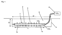
- Fig. 1 shows a container or pond 4 of diameter D filled with water 5 of depth D' for algae farming.
- a hose 1 comprising a circumferential closed wall 2 (i.e. without apertures formed into the wall) out of silicone having an outer surface 3.
- CO 2 is fed into an interior space defined by said wall 2 of the hose 1 and diffuses through the silicone wall 2 of the hose 1 into the water 5.
- the hose 1 has a length L along a longitudinal extension direction and a diameter D" as well as a wall thickness T.
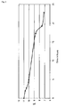
- CO 2 was discharged through the silicone hose 1 into drinking water 5 comprising NaOH residing in a tank 4 having a diameter D of 28cm.
- the pH of said mixture amounted to 10.99 initially.
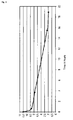
- CO 2 was discharged through said silicone hose 1 into water 5 containing algae. At first, CO 2 dosing was stopped until the pH of the water increased and then CO 2 dosing started again. Also here, the pH dropped over time as shown in Fig. 3 .
- the hose 1 resided in the water 5 with algae for three weeks and no scaling or fouling on the hose 1 occurred.
- the surface 3 of the hose 1 probably has a low pH due to the CO 2 and the bubbles formed all over the surface 3 of the hose 1 prevent fouling.
- the CO 2 enters the silicone hose 1 it has no moisture, but the hose 1 itself allows water to diffuse through the hose 1 and get into the interior space of the hose 1. So, in the beginning of the hose 1 the CO 2 is slowly moistened. As the CO 2 gas gets more moistened the transport through the hose 1 gets better, which can be noticed because there are more bubbles on the respective part on the outside of the hose 1.
- CO 2 is moistened with water by leading the gas through a water columm before dosing it into the silicone hose 1 to get a better efficiency of the CO 2 transport through the hose wall 2.
Landscapes
- Life Sciences & Earth Sciences (AREA)
- Engineering & Computer Science (AREA)
- Health & Medical Sciences (AREA)
- Chemical & Material Sciences (AREA)
- Bioinformatics & Cheminformatics (AREA)
- Organic Chemistry (AREA)
- Wood Science & Technology (AREA)
- Zoology (AREA)
- Biotechnology (AREA)
- Genetics & Genomics (AREA)
- Biomedical Technology (AREA)
- Biochemistry (AREA)
- General Engineering & Computer Science (AREA)
- General Health & Medical Sciences (AREA)
- Sustainable Development (AREA)
- Microbiology (AREA)
- Molecular Biology (AREA)
- Agricultural Chemicals And Associated Chemicals (AREA)
Abstract
The invention relates to a method for discharging CO2 into a liquid (5) comprising water and algae, wherein gaseous CO2 is discharged via a conduit (1) into said liquid (5). According to the invention, gaseous CO2 is diffused through a closed wall (2) of said conduit (1) into the liquid (5), wherein said wall (3) comprises a polysiloxane or is formed out of at least one polysiloxane. Furthermore, the invention relates to a corresponding system.
Description
- The invention relates to a method for growing algae, wherein CO2 is discharged into a liquid comprising water and algae according to
claim 1 as well as to a corresponding system according toclaim 5. - For growing algae CO2 has to be added to have an increased growth of algae.
- Algae are grown for nutrients, feed for fish and other animals, cosmetics, base products for medicine production, bio plastics, omega 3-6, and for the production of biodiesel and many other products. In principle, besides algae, the invention can be applied to all autotrophic CO2-assimilating organisms.
- For a high production rate of the algae one needs:
- Light, typically sun light,
- Nutrients,
- Water (e.g. fresh, brackish or salt water),
- CO2, and particularly
- Mixing (circulation).
- When using pure CO2 in algae farming the efficiency of solving the CO2 is very important. Most systems use perforated hoses or plates to solve the CO2. The water depth in algae farms is typically relatively low (e.g. 15 to 20 cm).
- The efficiency of the CO2 dosing on those depths is not high (30% to 90% depending on type of injection system and algae species). Often sumps are used to have a higher water depth and efficiency of the dosed CO2. This increases the costs of the algae pond.
- Further, a sump - from a hydrological point of view - is not a very good technical solution, since the flow speed in the sump normally decreases significantly so that the CO2 will build up and lower the efficiency of the CO2 exchange, and sedimentation of algae and other materials can occur.
- Based on the above, the problem underlying the present invention is to provide a method/system of the afore-mentioned kind that improves the efficiency of solving the CO2 in the liquid (e.g. water with algae).
- This problem is solved by a method having the features of
claim 1. Preferred embodiments are stated in the corresponding sub claims. - According to
claim 1, gaseous CO2 is diffused through a closed wall of said conduit into the liquid, wherein said wall of the conduit comprises a polysiloxane or is formed out of at least one polysiloxane. - Polysiloxanes (also denoted as silicones) are polymers that include silicon together with carbon, hydrogen, oxygen, and sometimes other elements.
- Silicones are mixed inorganic-organic polymers having the formula [R2SiO]n, where R is an organic group (e.g. methyl, ethyl, or phenyl). Silicones comprise an inorganic
silicon-oxygen backbone (···-Si-O-Si-O-Si-O-···) with organic side groups attached to
the silicon atoms, which are four-coordinate. - Furthermore, organic side groups may be used to link two or more of said -Si-O-backbones together. By varying the -Si-O- chain lengths, side groups, and crosslinking, silicones can be synthesized with a wide variety of properties and compositions. The most common siloxane, which is preferably used in the present invention, is linear polydimethylsiloxane (PDMS).
- Therefore, according to a preferred embodiment of the present invention said polysiloxane is PDMS.
- Further, preferably said conduit is a hose, particularly a flexible hose, wherein said wall particularly is a circumferential wall of said hose.
- Further, preferably, the gaseous CO2 is moistened with H2O before diffusing it through the wall of the conduit into the liquid.
- Preferably, the pressure of the CO2 in the conduit lies within the range from 0.2 bar(o) to 5bar(o), preferably in the range between 0.2 bar(o) and 4 bar(o). Preferably, the temperature of the water lies within the range from 10°C to 35°C.
- Further, the problem underlying the present invention is solved by a system having the features of
claim 5. Preferred embodiments are stated in the corresponding sub claims. - According to
claim 5, said conduit being designed to reside in the liquid comprises a closed wall designed for diffusing gaseous CO2 through said wall and into said surrounding liquid, wherein said wall comprises a polysiloxane or is formed out of at least one polysiloxane. - Preferably, said conduit is formed as a hose, particularly a flexible hose, wherein said wall particularly is a circumferential wall of said hose.
- In the following, further features, advantages and examples of the present invention shall be described with reference to the Figures, wherein
- Fig. 1
- shows a schematical cross sectional view of a silicone hose for dosing CO2 into water of an algae pond,
- Fig. 2
- shows pH versus time upon discharging CO2 via a silicone hose into water, and
- Fig. 3
- shows pH versus time upon discharging CO2 via a silicone hose into water containing algae.
-
Fig. 1 shows a container orpond 4 of diameter D filled withwater 5 of depth D' for algae farming. In order to discharge CO2 into thewater 5, ahose 1 comprising a circumferential closed wall 2 (i.e. without apertures formed into the wall) out of silicone having anouter surface 3. CO2 is fed into an interior space defined bysaid wall 2 of thehose 1 and diffuses through thesilicone wall 2 of thehose 1 into thewater 5. - The
hose 1 has a length L along a longitudinal extension direction and a diameter D" as well as a wall thickness T. - In a first example CO2 was discharged through the
silicone hose 1 intodrinking water 5 comprising NaOH residing in atank 4 having a diameter D of 28cm. The water depth was D'=15.5 cm. The pH of said mixture amounted to 10.99 initially. - As shown in
Fig. 2 , upon discharging CO2 via thesilicone hose 1 into thewater 5, the pH dropped with increasing time. - In a second example CO2 was discharged through said
silicone hose 1 intowater 5 containing algae. At first, CO2 dosing was stopped until the pH of the water increased and then CO2 dosing started again. Also here, the pH dropped over time as shown inFig. 3 . - Both tests were performed with a
silicone hose 1 having a diameter D"=8mm, a length L= 48 cm and a wall thickness T=1.5 mm. The CO2 pressure in thehose 1 during the tests was 1.5 bar(o).The temperature of the water was 25°C. The silicone used was PDMS. - On the outside of the
hose 1 bubbles were formed, presumably due to local oversaturation of gases. The bubbles stayed a relatively long time, e.g. within the range from 3 min to 5 min, on the hose's 1surface 3 before getting up to the surface of thewater 5 in thetank 4. - When releasing the bubbles from the
hose 1 by moving thehose 1, every time new bubbles formed. Presumably, CO2 is contained in said bubbles, which may possibly react to form bicarbonates and carbonates especially at higher pH. - The
hose 1 resided in thewater 5 with algae for three weeks and no scaling or fouling on thehose 1 occurred. - The
surface 3 of thehose 1 probably has a low pH due to the CO2 and the bubbles formed all over thesurface 3 of thehose 1 prevent fouling. - Furthermore, it was observed that when dosing pure CO2 in a
first part 1a of thehose 1, less transport of CO2 through the hose wall occurred than in thesecond part 1b of the hose. - This can be related to moisture diffusing through the
silicone wall 2 of thehose 1 which helps the transport of CO2 through thehose wall 2. When the CO2 enters thesilicone hose 1 it has no moisture, but thehose 1 itself allows water to diffuse through thehose 1 and get into the interior space of thehose 1. So, in the beginning of thehose 1 the CO2 is slowly moistened. As the CO2 gas gets more moistened the transport through thehose 1 gets better, which can be noticed because there are more bubbles on the respective part on the outside of thehose 1. - Preferably, CO2 is moistened with water by leading the gas through a water columm before dosing it into the
silicone hose 1 to get a better efficiency of the CO2 transport through thehose wall 2. Other ways are also conceivable.Reference Numerals 1 conduit or hose 2 Wall 3 Surface 4 Container, tank or pond 5 Liquid (e.g. water with algae) 6 CO2 source D, D' Diameter D" Depth T Thickness L Length
Claims (7)
- Method for growing algae, wherein CO2 is discharged into a liquid (5) comprising water and algae so that CO2 is assimilated by said algae, wherein gaseous CO2 is discharged via a conduit (1) residing in said liquid (5) into said liquid (5),
wherein
gaseous CO2 is diffused through a closed wall (2) of said conduit (1) into the liquid (5), wherein said wall (3) comprises a polysiloxane or is formed out of at least one polysiloxane. - Method according to claim 1, characterized in that said polysiloxane is Polydimethylsiloxane (PDMS).
- Method according to claim 1 or 2, characterized in that said conduit (1) is a hose, wherein said wall (2) particularly is a circumferential wall (2) of said hose (1).
- Method according to one of the preceding claims, characterized in that the gaseous CO2 is moistened with H2O before diffusing it through the wall (2) of the conduit (1) into the liquid (5).
- System for growing algae, comprising:- a container (4) containing a liquid comprising water and algae,- a conduit (1) for discharging gaseous CO2 into the liquid (5), and- a CO2 source (6) designed to be in flow connection with said conduit (1),wherein
said conduit (1) comprises a closed wall (2) designed for diffusing gaseous CO2 through said wall (2) and into said liquid (5), wherein said wall (2) comprises a polysiloxane or is formed out of at least one polysiloxane. - System according to claim 5, characterized in that said polysiloxane is Polydimethylsiloxane (PDMS).
- System according to claim 5 or 6, characterized in that said conduit (1) is a hose, wherein said wall (2) particularly is a circumferential wall (2) of said hose (1).
Priority Applications (1)
| Application Number | Priority Date | Filing Date | Title |
|---|---|---|---|
| EP14004016.3A EP3026105A1 (en) | 2014-11-27 | 2014-11-27 | Silicone hose for solving CO2 in water for algae production |
Applications Claiming Priority (1)
| Application Number | Priority Date | Filing Date | Title |
|---|---|---|---|
| EP14004016.3A EP3026105A1 (en) | 2014-11-27 | 2014-11-27 | Silicone hose for solving CO2 in water for algae production |
Publications (1)
| Publication Number | Publication Date |
|---|---|
| EP3026105A1 true EP3026105A1 (en) | 2016-06-01 |
Family
ID=52102344
Family Applications (1)
| Application Number | Title | Priority Date | Filing Date |
|---|---|---|---|
| EP14004016.3A Withdrawn EP3026105A1 (en) | 2014-11-27 | 2014-11-27 | Silicone hose for solving CO2 in water for algae production |
Country Status (1)
| Country | Link |
|---|---|
| EP (1) | EP3026105A1 (en) |
Citations (2)
| Publication number | Priority date | Publication date | Assignee | Title |
|---|---|---|---|---|
| WO1995026806A1 (en) * | 1994-03-30 | 1995-10-12 | Imperial College Of Science, Technology & Medicine | Permeation and biological treatment of waste gas |
| WO2014123906A1 (en) * | 2013-02-05 | 2014-08-14 | Medarray, Inc. | Siloxane based hollow fibers |
-
2014
- 2014-11-27 EP EP14004016.3A patent/EP3026105A1/en not_active Withdrawn
Patent Citations (2)
| Publication number | Priority date | Publication date | Assignee | Title |
|---|---|---|---|---|
| WO1995026806A1 (en) * | 1994-03-30 | 1995-10-12 | Imperial College Of Science, Technology & Medicine | Permeation and biological treatment of waste gas |
| WO2014123906A1 (en) * | 2013-02-05 | 2014-08-14 | Medarray, Inc. | Siloxane based hollow fibers |
Non-Patent Citations (3)
| Title |
|---|
| MONTOYA, PATRICK J.: "Membrane Gas Exchange Using Hollow Fiber Membranes to Separate Gases from Liquid and Gaseous Streams .", 7 February 2010 (2010-02-07), XP002739068, Retrieved from the Internet <URL:https://www.permselect.com/files/Using_Membranes_for_Gas_Exchange.pdf> [retrieved on 20150429] * |
| SIYE CHEN ET AL: "Photolithotrophic cultivation of Laminaria japonica gametophyte cells in a silicone tubular membrane-aerated photobioreactor", PLANT CELL, TISSUE AND ORGAN CULTURE, KLUWER ACADEMIC PUBLISHERS, DO, vol. 93, no. 1, 1 February 2008 (2008-02-01), pages 29 - 38, XP019581368, ISSN: 1573-5044 * |
| YUAN-KUN LEE AND HUEY-KWAN HING: "Supplying CO2 to photosynthetic algal cultures by diffusion through gas-permeable membranes.", APPLIED MICROBIOLOGY AND BIOTECHNOLOGY, vol. 31, 1989, pages 289 - 301, XP002739067 * |
Similar Documents
| Publication | Publication Date | Title |
|---|---|---|
| KR101150740B1 (en) | Nanobubble-containing liquid producing apparatus and nanobubble-containing liquid producing method | |
| KR102442879B1 (en) | Composition containing nano-bubbles in a liquid carrier | |
| JP6548220B2 (en) | Aquaponics system | |
| JP7218016B2 (en) | Fine bubble forming device | |
| JP2012095630A (en) | Parallel cultivation system for aquatic animal and plant by using microorganism activated with micro-nanobubble | |
| WO2007136970A3 (en) | Method and apparatus for enhancing aquatic environments | |
| CA3052371C (en) | A low-pressure, reversible airlift mixing system for use with a membrane aerated biofilm reactor | |
| CN115867131A (en) | Fish farming method in recirculating aquaculture system | |
| EP2534946A1 (en) | Method to reduce nitrogen concentration in salt water | |
| TW200938079A (en) | An apparatus for culturing aquatic organisms | |
| AU2011368432A1 (en) | A system for biological treatment | |
| CN108601328A (en) | The hydroponic culture system of seawater and the cultivation system for seeding and seedling raising are used | |
| KR20120004892A (en) | Seawater Suction Device for Aquarium Water Purifier | |
| Omofunmi et al. | Development of a paddle wheel aerator for small and medium fish farmers in Nigeria | |
| KR101109763B1 (en) | Underwater mixing / stirring device for wastewater treatment | |
| WO2006047224A3 (en) | Continuous chemical feeder and method of use thereof | |
| JP2010046037A (en) | Breeding tank for floating organisms such as eel larvae and feeding method for floating organisms | |
| CN105230548A (en) | Tilapia high yield breeding method | |
| CN109475827A (en) | Mixed treatment body, mixed treatment method, mixed production fluid, fluid mixer, fluid mixed treatment device, fish and shellfish culture system and fish and shellfish culture method | |
| CN107347745B (en) | Fry breeding method | |
| KR20100022879A (en) | Method and system for improving water and/or ground quality in farm of marine products | |
| US9422068B2 (en) | Drinking water delivery system and method | |
| JP2010137157A (en) | Nitric acid removal bioreactor, method for generating nitric acid removal biofilm, and method for removing nitric acid | |
| CN109661376A (en) | Biological Treatment Methods of Organic Drainage | |
| JP2016077270A (en) | Land rearing device of tuna |
Legal Events
| Date | Code | Title | Description |
|---|---|---|---|
| PUAI | Public reference made under article 153(3) epc to a published international application that has entered the european phase |
Free format text: ORIGINAL CODE: 0009012 |
|
| AK | Designated contracting states |
Kind code of ref document: A1 Designated state(s): AL AT BE BG CH CY CZ DE DK EE ES FI FR GB GR HR HU IE IS IT LI LT LU LV MC MK MT NL NO PL PT RO RS SE SI SK SM TR |
|
| AX | Request for extension of the european patent |
Extension state: BA ME |
|
| STAA | Information on the status of an ep patent application or granted ep patent |
Free format text: STATUS: THE APPLICATION IS DEEMED TO BE WITHDRAWN |
|
| 18D | Application deemed to be withdrawn |
Effective date: 20161202 |