EP3025996A1 - Yarn joining device, yarn winding machine, and yarn joining method - Google Patents
Yarn joining device, yarn winding machine, and yarn joining method Download PDFInfo
- Publication number
- EP3025996A1 EP3025996A1 EP15194903.9A EP15194903A EP3025996A1 EP 3025996 A1 EP3025996 A1 EP 3025996A1 EP 15194903 A EP15194903 A EP 15194903A EP 3025996 A1 EP3025996 A1 EP 3025996A1
- Authority
- EP
- European Patent Office
- Prior art keywords
- yarn
- joining
- air
- yarn joining
- spun
- Prior art date
- Legal status (The legal status is an assumption and is not a legal conclusion. Google has not performed a legal analysis and makes no representation as to the accuracy of the status listed.)
- Granted
Links
- 238000005304 joining Methods 0.000 title claims abstract description 312
- 238000004804 winding Methods 0.000 title claims description 83
- 238000000034 method Methods 0.000 title claims description 16
- 238000011144 upstream manufacturing Methods 0.000 claims abstract description 52
- 238000009987 spinning Methods 0.000 claims description 83
- 238000011176 pooling Methods 0.000 claims description 70
- 238000002347 injection Methods 0.000 claims description 22
- 239000007924 injection Substances 0.000 claims description 22
- 238000005452 bending Methods 0.000 claims description 11
- 230000001276 controlling effect Effects 0.000 description 16
- 239000000835 fiber Substances 0.000 description 9
- 238000003825 pressing Methods 0.000 description 9
- 230000007246 mechanism Effects 0.000 description 7
- 230000009471 action Effects 0.000 description 6
- 230000007547 defect Effects 0.000 description 4
- 230000006870 function Effects 0.000 description 3
- 238000012806 monitoring device Methods 0.000 description 3
- 230000008569 process Effects 0.000 description 3
- 230000001105 regulatory effect Effects 0.000 description 3
- 230000008901 benefit Effects 0.000 description 2
- 230000007423 decrease Effects 0.000 description 2
- 238000004519 manufacturing process Methods 0.000 description 2
- 230000003287 optical effect Effects 0.000 description 2
- 230000004044 response Effects 0.000 description 2
- 241000237519 Bivalvia Species 0.000 description 1
- 230000005856 abnormality Effects 0.000 description 1
- 230000033228 biological regulation Effects 0.000 description 1
- 230000008859 change Effects 0.000 description 1
- 235000020639 clam Nutrition 0.000 description 1
- 238000010276 construction Methods 0.000 description 1
- 238000005520 cutting process Methods 0.000 description 1
- 230000008034 disappearance Effects 0.000 description 1
- 230000004048 modification Effects 0.000 description 1
- 238000012986 modification Methods 0.000 description 1
- 239000002994 raw material Substances 0.000 description 1
- 230000009467 reduction Effects 0.000 description 1
- 230000032258 transport Effects 0.000 description 1
- 238000004018 waxing Methods 0.000 description 1
Images





Classifications
-
- B—PERFORMING OPERATIONS; TRANSPORTING
- B65—CONVEYING; PACKING; STORING; HANDLING THIN OR FILAMENTARY MATERIAL
- B65H—HANDLING THIN OR FILAMENTARY MATERIAL, e.g. SHEETS, WEBS, CABLES
- B65H69/00—Methods of, or devices for, interconnecting successive lengths of material; Knot-tying devices ;Control of the correct working of the interconnecting device
- B65H69/06—Methods of, or devices for, interconnecting successive lengths of material; Knot-tying devices ;Control of the correct working of the interconnecting device by splicing
-
- B—PERFORMING OPERATIONS; TRANSPORTING
- B65—CONVEYING; PACKING; STORING; HANDLING THIN OR FILAMENTARY MATERIAL
- B65H—HANDLING THIN OR FILAMENTARY MATERIAL, e.g. SHEETS, WEBS, CABLES
- B65H51/00—Forwarding filamentary material
- B65H51/20—Devices for temporarily storing filamentary material during forwarding, e.g. for buffer storage
- B65H51/205—Devices for temporarily storing filamentary material during forwarding, e.g. for buffer storage by means of a fluid
-
- B—PERFORMING OPERATIONS; TRANSPORTING
- B65—CONVEYING; PACKING; STORING; HANDLING THIN OR FILAMENTARY MATERIAL
- B65H—HANDLING THIN OR FILAMENTARY MATERIAL, e.g. SHEETS, WEBS, CABLES
- B65H59/00—Adjusting or controlling tension in filamentary material, e.g. for preventing snarling; Applications of tension indicators
- B65H59/10—Adjusting or controlling tension in filamentary material, e.g. for preventing snarling; Applications of tension indicators by devices acting on running material and not associated with supply or take-up devices
- B65H59/105—Adjusting or controlling tension in filamentary material, e.g. for preventing snarling; Applications of tension indicators by devices acting on running material and not associated with supply or take-up devices the material being subjected to the action of a fluid
-
- B—PERFORMING OPERATIONS; TRANSPORTING
- B65—CONVEYING; PACKING; STORING; HANDLING THIN OR FILAMENTARY MATERIAL
- B65H—HANDLING THIN OR FILAMENTARY MATERIAL, e.g. SHEETS, WEBS, CABLES
- B65H2701/00—Handled material; Storage means
- B65H2701/30—Handled filamentary material
- B65H2701/31—Textiles threads or artificial strands of filaments
Definitions
- the present invention generally relates to a yarn joining device having a yarn joining section that joins yarn ends of a yarn, a yarn winding machine, and a yarn joining method.
- Yarn winding machines that include a yarn joining section that makes a discontinuous yarn continuous are known in the art.
- Japanese Patent Application Laid-open No. 2000-290839 discloses a yarn joining method including, when yarn breakage occurs in a spinning device, pulling a yarn end (parent yarn) wound around a package, conveying the yarn end to a spinning section, and performing piecing.
- the yarn joining performed in this yarn joining method does not include joining one yarn end to another yarn end, instead, compressed air is blown on the parent yarn when the parent yarn is conveyed to the spinning section thereby absorbing slack of the parent yarn.
- Japanese Patent Application Laid-open No. 2013-067475 discloses a spinning machine (yarn winding machine) including a yarn joining device that performs the yarn joining with a method that is different from the one disclosed in Japanese Patent Application Laid-open No. 2000-290839 .
- This spinning machine includes a winding device, a spinning device, a yarn joining device, and a yarn route regulating member.
- the yarn joining device is formed as a splicer device that forms a splicing point by applying twists to the yarn ends by a swirling air current.
- the yarn route regulating member bends a spun yarn by being in contact with the spun yarn during the yarn joining. The bent state of the spun yarn formed by the yarn route regulating member is maintained until winding of the spun yarn by the winding device is started.
- a yarn joining device includes a yarn joining section that performs yarn joining in a state in which a yarn is held in a bent state; and a yarn slack removing section that removes slack of the yarn positioned on a yarn joining path that passes through the yarn joining section by applying a force on the yarn upstream of the yarn joining section.
- a yarn winding machine includes a spinning device that forms a yarn by spinning; a yarn pooling device that pools the yarn formed by the spinning device; a winding device that winds the yarn from the yarn pooling device and forms a package; a yarn joining section that performs yarn joining at a position between the spinning device and the winding device in a state in which the yarn is held in a bent state; a yarn-route guiding member that guides the yarn on a downstream side of the yarn pooling device in a yarn route of the yarn; and a yarn slack removing section that removes slack of the yarn positioned on a yarn joining path that passes through the yarn joining section by applying a force on the yarn upstream of the yarn joining section but downstream of the yarn-route guiding member.
- a yarn joining method of joining yarn ends includes holding a yarn in a bent state; joining the yarn ends by using a yarn joining section; and removing, after completion of the holding, slack of the yarn that was generated by bending of the yarn in the holding on upstream side of the yarn joining section.
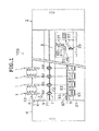
- the spinning machine 100 shown in FIG. 1 includes plural spinning units (yarn winding units) 1 arranged side by side, a yarn joining carrier 2, a blower box 3, and a motor box 4.
- the terms "upstream” and “downstream” refer to the upstream and the downstream in a travelling direction of a fiber bundle 11 or a spun yarn 10 when the spun yarn 10 is formed and wound in the spinning unit 1.
- the motor box 4 is arranged on one side in the direction in which the plural spinning units 1 are arranged and it houses a common driving source for the spinning units 1.
- the blower box 3 is arranged on the other side in the direction in which the plural spinning units 1 are arranged and the other side is the opposite side of the side on which the motor box 4 is arranged.
- a blower is housed inside the blower box 3.
- the blower functions as a negative pressure source that supplies the negative pressure to each of the spinning units 1 and the yarn joining carrier 2.
- a compressor that functions as a compressed air source that supplies compressed air to each of the spinning units 1 and the yarn joining carrier 2 is arranged at a suitable location separated from the spinning machine 100. The compressed air is supplied from the compressor to the spinning machine 100 via one or more air pipes.
- One or more regulators that adjust an air pressure of the compressed air are arranged in the blower box 3 or the motor box 4.
- the compressed air to be supplied to the spinning machine 100 via the air pipes is supplied to each of the spinning units 1 and the yarn joining carrier 2 through the regulators.
- the method of supplying the compressed air to the spinning units 1 and the yarn joining carrier 2 is not limited to the one explained here.
- the spinning unit 1 is configured as an air spinning unit that performs spinning by applying twists to the fiber bundle 11 by the action of a swirling air current.
- each of the spinning units 1 mainly includes, sequentially arranged from upstream to downstream, a drafting device 5, a spinning device 6, a yarn pooling device 7, and a winding device 8.
- the fiber bundle 11 conveyed from the drafting device 5 is spun by the spinning device 6 thereby forming the spun yarn 10
- the spun yarn 10 is wound around a bobbin 81 by the winding device 8 thereby forming a package 82.
- the drafting device 5 includes, sequentially from the upstream, four drafting rollers, namely, a back roller 51, a third roller 52, a middle roller 54 with a rubber apron belt 53 stretched thereover, and a front roller 55. Each of the drafting rollers is rotationally driven at a predetermined rotation speed. Moreover, the drafting device 5 includes an opposing roller arranged facing each of the drafting rollers. The drafting device 5 transports a sliver 12, which is the raw material of the fiber bundle 11, by nipping the sliver 12 between the drafting rollers and the opposing rollers thereby forming the fiber bundle 11 by stretching (drafting) the sliver 12 until a predetermined width is obtained.
- the spinning device 6 is located downstream of the drafting device 5 and forms the spun yarn 10 by applying twists to the fiber bundle 11 supplied from the drafting device 5.
- a device that applies twists to the fiber bundle 11 by using a swirling air current is employed as the spinning device 6 in the present embodiment.
- the yarn pooling device 7 is arranged between the spinning device 6 and the winding device 8.
- the yarn pooling device 7 includes a yarn pooling roller 71, a yarn hooking member 72, and an electric motor 73.
- the electric motor 73 can rotationally drive the yarn pooling roller 71.
- the yarn pooling device 7 functions as a kind of a buffer that temporarily pools the spun yarn 10 at a position between the spinning device 6 and the winding device 8.
- the yarn pooling roller 71 is configured so as to temporarily pool the spun yarn 10 by winding a certain amount of the spun yarn 10 on an outer circumferential surface thereof.
- the yarn hooking member 72 that can hook the spun yarn 10 is mounted on a downstream end portion of the yarn pooling roller 71.
- the yarn hooking member 72 is supported in a rotatable manner relatively to the yarn pooling roller 71.
- a permanent magnet is attached to any one of the yarn hooking member 72 and the yarn pooling roller 71, and a magnetic hysteresis member is attached to the other of the yarn hooking member 72 and the yarn pooling roller 71.
- These magnetic means generate a torque against a relative rotation of the yarn hooking member 72 with respect to the yarn pooling roller 71. Therefore, only when a force exceeding this torque is applied on the yarn hooking member 72 (i.e., when a tension of a predetermined amount or larger is applied to the spun yarn 10), the yarn hooking member 72 is rotated relatively to the yarn pooling roller 71 whereby the spun yarn 10 wound around the yarn pooling roller 71 can be unwound.
- the yarn pooling roller 71 and the yarn hooking member 72 are integrally rotated whereby the spun yarn 10 that has been wound around the yarn pooling roller 71 is not unwound.
- the spun yarn 10 is pooled on the yarn pooling roller 71 when the yarn pooling roller 71 rotates.
- the yarn pooling device 7 operates such that the unwinding amount of the spun yarn 10 increases when the yarn tension on the downstream side increases, and the unwinding amount of the spun yarn 10 decreases when the yarn tension decreases (when the spun yarn 10 is about to slacken). With this operation, the yarn pooling device 7 absorbs the slack of the spun yarn 10 and can apply an appropriate tension on the spun yarn 10 at any given time during the yarn winding. Furthermore, because the yarn hooking member 72 operates to absorb any variation of the tension applied on the spun yarn 10 between the yarn pooling device 7 and the winding device 8, the variation of the tension is prevented from affecting the spun yarn 10 between the air spinning device 6 and the yarn pooling device 7.
- a yarn-route guiding member 74 that guides to the downstream side the spun yarn 10 pulled from the yarn pooling device 7 is arranged downstream of the yarn pooling device 7.
- the yarn-route guiding member 74 guides the spun yarn 10, which is pulled out from an axial end of the outer circumferential surface of the yarn pooling roller 71, such that the spun yarn 10 passes over a line that extends from a rotation axis of the yarn pooling roller 71. Accordingly, when the yarn hooking member 72 is rotating in a state in which it has hooked the spun yarn 10, a substantially conical balloon 75 is formed between the yarn pooling roller 71 and the yarn-route guiding member 74 because of the revolving of the spun yarn 10.
- the winding device 8 forms the package 82 by winding the spun yarn 10 around the bobbin 81 while traversing the spun yarn 10.
- the winding device 8 includes a cradle arm 83 and a winding drum 84.
- the cradle arm 83 is rotatably supported by a support shaft 86.
- the cradle arm 83 is capable of rotatably supporting the bobbin 81 (or the package 82) around which the spun yarn 10 is to be wound.
- the winding drum 84 is rotationally driven in a predetermined direction at a constant rotational speed. By rotating the cradle arm 83 with the support shaft 86 as a center, the outer circumferential surface of the supported bobbin 81 (or the package 82) can be brought into contact with or separated from the winding drum 84.
- the bobbin 81 When the outer circumferential surface of the bobbin 81 (or the package 82) is brought into contact with the rotationally driven winding drum 84, the bobbin 81 (or the package 82) is rotated following the rotation of the winding drum 84 whereby the spun yarn 10 is wound on the circumferential surface of the bobbin 81 (or the package 82).
- a traversing device 85 includes a traversing guide 87 that can hook and guide the spun yarn 10.
- the traversing guide 87 is driven by a not-shown driving means to perform reciprocating movement in a direction that is parallel to the rotation axis of the winding drum 84. With this configuration, when the traversing guide 87 with the spun yarn 10 hooked thereby is caused to make the reciprocating movement while the winding drum 84 is rotating, the spun yarn 10 can be wound around the package 82 while traversing the spun yarn 10.
- the winding device 8 includes a not-shown brake mechanism that applies brake to the rotation of the package 82.
- the configuration of the brake mechanism is not particularly limited, and can include, for example, a brake shoe that contacts a member that integrally rotates with the package 82 and a pneumatic cylinder that presses the brake shoe to this member.
- a yarn quality monitoring device 9 that monitors the quality of the spun yarn 10 is arranged between the spinning device 6 and the yarn pooling device 7.
- the yarn quality monitoring device 9 monitors the state (thickness and the like) of the running spun yarn 10 by using an optical transmission-type sensor to detect a yarn defect (a place where there is an abnormality in the spun yarn 10) in the spun yarn 10.
- the sensor with which the yarn quality monitoring device 9 monitors the spun yarn 10 is not limited to the optical transmission-type sensor, and can, for example, be an electrostatic capacitance-type sensor. A foreign matter included in the spun yarn 10 can be detected as the yarn defect.
- the yarn joining carrier 2 includes the yarn joining device 20, a yarn catching section (a suction pipe 21 and a suction mouth 22), and a reverse rotation mechanism 29.
- the yarn joining carrier 2 includes a not-shown carrier controlling section that controls various components of the yarn joining carrier 2.
- the yarn joining device 20 includes a yarn joining section 25 that is constructed as a splicer device that forms a splicing point by applying twists to the yarn ends by the swirling air current.
- the side of the yarn joining device 20 and the yarn joining section 25 closer to a yarn route, which is a running path of the spun yarn 10 shall be referred to as a front side and the side that is far from the yarn path shall be referred to as a far side.
- the direction that extends from the front side to the far side, or vice versa, of the yarn joining device 20 or the yarn joining section 25 shall be referred to as a front-back direction.
- each of the suction pipe 21 and the suction mouth 22 is rotatable in the vertical direction about a corresponding axis.
- Each of the suction pipe 21 and the suction mouth 22 can catch a yarn end by suction by generating a suction air current at tip ends thereof.
- the carrier controlling section rotates the suction pipe 21 and also generates a suction air current at the tip end thereof. Accordingly, the suction pipe 21 catches by suction the yarn end of the spun yarn 10 (the spun yarn 10) supplied from the spinning device 6. Simultaneously, the carrier controlling section rotates the suction mouth 22 and also generates a suction air current at the tip end thereof. Accordingly, the suction mouth 22 catches by suction the yarn end of the spun yarn 10 (the spun yarn 10) from the package 82.
- the carrier controlling section rotates the suction pipe 21 and the suction mouth 22.
- the yarn ends caught by the suction pipe 21 and the suction mouth 22 are guided to a region on the front side of the yarn joining section 25 (i.e., a region on the left side in FIG. 4 ).
- the spun yarn 10 from the package 82 and the spun yarn 10 from the spinning device 6 are set in a path (yarn joining path) where the yarn joining section 25 performs the yarn joining.
- the spun yarn 10 from the spinning device 6 sucked and caught by the suction pipe 21 is referred to as a first yarn
- the spun yarn 10 from the package 82 sucked and caught by the suction mouth 22 is referred to as a second yarn.
- the reverse rotation mechanism 29 includes a supporting arm 30 that is approachable/ retractable toward the winding device 8 from the yarn joining carrier 2, and a reverse rotation roller 31 supported on a tip end of the supporting arm 30.
- the reverse rotation roller 31 can be rotationally driven by a not-shown electric motor in a direction that is opposite of the direction in which the winding drum 84 rotates.
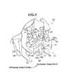
- FIG. 5 shows a state when the yarn joining device 20 (yarn joining section 25) is seen from the upstream side.
- the yarn joining section 25 mainly includes a yarn joining nozzle 91, a pair of guiding plates 92, a pair of yarn shifting levers 93, a pair of yarn pressing levers 94, a pair of cutters 95, a pair of clamping members 96, and a pair of untwisting pipes 97.
- the yarn joining nozzle 91 is arranged on the front side of the yarn joining section 25 (i.e., on the side closer to the yarn path that is the running path of the spun yarn 10).
- a yarn joining hole 98 through which the spun yarn 10 can pass is formed in the yarn joining nozzle 91.
- An injection port for passing the compressed air to be injected is formed inside the yarn joining hole 98.
- the yarn joining nozzle 91 can generate a swirling air current inside the yarn joining hole 98 by injecting compressed air from the injection port inside the yarn joining hole 98.
- one unit of each of the guiding plates 92, the yarn shifting levers 93, the yarn pressing levers 94, the cutters 95, the clamping members 96, and the untwisting pipes 97 is arranged on each of the upstream side and the downstream side of the yarn joining nozzle 91.
- two slits As shown in FIG. 5 , two slits, a first slit 15 and a second slit 16, that open the front side of the yarn joining section 25, are formed side by side in each of the two guiding plates 92.
- the four slits formed in the two guiding plates 92 are parallel to each other.
- the first yarn caught by the suction pipe 21 is guided into the second slits 16 of the two guiding plates 92, and the second yarn caught by the suction mouth 22 is guided into the first slits 15 of the two guiding plates 92.
- the first yarn and the second yarn can be guided to positions at which the later-explained yarn shifting leaver 93 is able to shift those yarns.
- the yarn joining path which is the path of the spun yarn 10 (yarn end) where the yarn joining section 25 performs the yarn joining, is made to pass through the yarn joining section 25 from the second slits 16 in the upstream guiding plate 92.
- the upstream guiding plate 92 is a member that guides the spun yarn 10 to the yarn joining path.
- the two yarn shifting levers 93 are rotatable simultaneously in two directions about an axis arranged on the side of the yarn joining nozzle 91.
- the two directions are a direction (closing direction) from where the levers enter between the two guiding plates 92 and a direction (opening direction) from where the levers come out from between the two guiding plates 92.
- FIG. 5 shows a state in which the yarn shifting levers 93 have been rotated in the opening direction
- FIG. 6 shows a state in which the yarn shifting levers 93 have been rotated in the closing direction.
- the yarn shifting levers 93 By rotating the yarn shifting levers 93 in the closing direction, the first yarn is pushed in the interior of the second slits 16 and the second yarn is pushed in the interior of the first slits 15. By further rotating in the closing direction, as shown in FIG. 6 , the yarn shifting levers 93 can guide the first yarn and the second yarn into the yarn joining hole 98.
- each of the yarn shifting levers 93 enters into the corresponding space (toward the interior of the yarn joining section 25) when rotated in the closing direction.
- the first yarn and the second yarn shifted by the pair of the yarn shifting levers 93 are bent, as shown in FIG. 6 , in a V-shape in the spaces between the yarn joining nozzle 91 and each of the guiding plates 92.
- the two yarn pressing levers 94 are, as shown in FIG. 5 , simultaneously rotatable about an axis arranged near the rotation axis of the yarn shifting levers 93.
- Each of the two yarn pressing levers 94 when the yarn joining nozzle 91 performs the yarn joining, rotates in the closing direction and respectively presses the first yarn and the second yarn thereby positioning the first yarn and the second yarn.
- One cutter 95 is arranged on a surface, which faces the yarn joining nozzle 91, of each of the two guiding plates 92.
- Each of the cutters 95 can cut the spun yarn 10.
- the cutter 95 arranged on the upstream guiding plate 92 can cut the second yarn that has entered the first slits 15 and the cutter 95 arranged on the downstream guiding plate 92 can cut the first yarn that has entered the second slits 16.
- One clamping member 96 is arranged on a surface, which is on the opposite side of the surface that faces the yarn joining nozzle 91, of each of the two guiding plates 92.
- Each of the clamping members 96 includes a movable member 96a and a non-movable member 96b.
- One pair of the movable member 96a and the non-movable member 96b is arranged across the first slits 15.
- Other pair of the movable member 96a and the non-movable member 96b is arranged across the second slits 16.
- the movable members 96a can be switched between a state in which they are pressed against and are in contact with the non-movable members 96b and a state in which they are separated from the non-movable members 96b.
- Each of the clamping members 96 clamps and holds the spun yarn 10, so that the spun yarn 10 does not move, by causing the movable member 96a to press against the non-movable member 96b in a state in which the spun yarn 10 is sandwiched between the movable member 96a and the non-movable member 96b.
- the clamping member 96 arranged on the upstream guiding plate 92 clamps and holds the first yarn that has entered the second slits 16.
- the clamping member 96 arranged on the downstream guiding plate 92 clams and holds the second yarn that has entered the first slits 15.
- the hold on the spun yarn 10 can be released by causing the movable members 96a and the non-movable members 96b to move apart.
- Each of the two untwisting pipes 97 is an elongated cylinder arranged such that the longitudinal direction thereof is parallel to the longitudinal direction of the other untwisting pipe 97 and also parallel to the front-back direction of the yarn joining section 25.
- the two untwisting pipes 97 are arranged side by side extending in a direction that is substantially parallel to the running direction of the yarn.
- One end of each of the untwisting pipes 97 opens in front of the yarn joining section 25.
- An air injection hole is formed in each of the untwisting pipes 97.
- the yarn shifting levers 93, the yarn pressing levers 94, the cutters 95, the clamping members 96, and the like, for example, are caused to operate in conjunction with each other with a cam mechanism. Accordingly, the later-explained yarn joining work can be performed smoothly.
- the package 82 is separated from the winding drum 84, and the rotation of the package 82 is stopped by operating the brake mechanism. Furthermore, the spun yarn 10 that has been pooled on the yarn pooling roller 71 of the particular spinning unit 1 is completely removed by a not-shown removing device leading to a state in which no spun yarn 10 is present on the yarn pooling roller 71.
- the spinning unit 1 requests the yarn joining carrier 2 to perform the yarn joining work.
- the yarn joining carrier 2 travels to the spinning unit 1 and stops.
- the carrier controlling section rotates the suction pipe 21 and the suction mouth 22 to respectively suck and catch the first yarn and the second yarn.
- the carrier controlling section causes the reverse rotation roller 31 of the reverse rotation mechanism 29 to come in contact with the package 82, and drives the reverse rotation roller 31 in the direction that is opposite of the direction in which the winding drum 84 rotates.
- the package 82 is rotated in the opposite direction (which may be referred to as an unwinding direction in the below explanation) that is opposite of the winding direction that is the direction in which the bobbin 81 (or the package 82) is rotated when the spun yarn 10 is wound around the bobbin 81 (or the package 82).
- the spun yarn 10 presents on the surface of the package 82 is sucked with the suction mouth 22 to draw the spun yarn 10 from the package 82.
- the carrier controlling section causes the suction pipe 21 and the suction mouth 22 to rotate so that the caught first yarn and the caught second yarn are guided to the front side of the yarn joining section 25.
- the yarn joining section 25 causes the pair of the yarn shifting levers 93 to rotate and come in contact with the spun yarn 10 thereby inserting the spun yarn 10 into the yarn joining hole 98 of the yarn joining nozzle 91.
- the yarn joining section 25, in the state shown in FIG. 6 holds the spun yarn 10 (the first yarn and the second yarn) with the pair of the clamping members 96.
- the rotation in the unwinding direction of the package 82 by the reverse rotation roller 31 is stopped.
- the spun yarn 10 (first yarn) is hooked by a suitable means on the yarn hooking member 72 of the yarn pooling device 7, and pooling of the spun yarn 10 on the yarn pooling roller 71 is started.
- the carrier controlling section starts injection of the compressed air into the pair of the untwisting pipes 97. Accordingly, an air current that flows toward the back side of the yarn joining section 25 is generated inside each of the untwisting pipes 97 whereby a suction air current is generated at the opening of each of the untwisting pipes 97.
- the carrier controlling section operates the pair of the cutters 95 and cuts the first yarn at a point between the suction pipe 21 and the yarn joining section 25 and cuts the second yarn at a point between the suction mouth 22 and the yarn joining section 25, respectively.
- the two yarn ends generated by these cuttings are sucked by the untwisting pipes 97 and drawn into the interior of the untwisting pipes 97. As shown in FIG. 7 , twists of each of the yarn ends are released by the action of the air current present inside each of the untwisting pipes 97.
- the carrier controlling section stops the injection of the compressed air into each of the untwisting pipes 97. Furthermore, the carrier controlling section, by further bending the spun yarn 10 by using the pair of the yarn shifting levers 93 and the pair of the yarn pressing levers 94, draws each of the untwisted yarns from each of the untwisting pipes 97. The two yarn ends drawn from the pair of the untwisting pipes 97 are set in the yarn joining hole 98 of the yarn joining nozzle 91, as shown in FIG. 8 , in mutually overlapping manner.
- the yarn joining section 25 injects the compressed air into the yarn joining hole 98.
- a swirling current is generated in the yarn joining hole 98 whereby twists are applied to the fibers constituting each of the yarn ends.
- the yarn end of the first yarn and the yarn end of the second yarn are entangled by the twisting and a splicing point is formed.
- the yarn joining section 25 includes a not-shown splicing-point length adjusting device that can adjust a shifting amount (in other words, the degree of bending of the spun yarn 10 during the yarn joining work) by which the spun yarn 10 is to be shifted by the pair of the yarn shifting levers 93.
- the splicing-point length adjusting device can change the length of the splicing point by adjusting the length by which the yarn ends overlap in the yarn joining hole 98 by adjusting the shifting amount of the yarn shifting levers 93.
- the carrier controlling section stops the injection of the air into the yarn joining hole 98. Furthermore, the carrier controlling section causes the hold on the spun yarn 10 by the pair of the clamping members 96 to be released, and causes the regulation of the yarn route by the pair of the yarn shifting levers 93 and the pair of the yarn pressing levers 94 to be released. With this, the yarn joining operation performed by the yarn joining section 25 is completed.
- the outer circumferential surface of the package 82 is made to contact with the rotating winding drum 84. Accordingly, the rotation of the package 82 is started and the winding of the spun yarn 10 is resumed.
- the spun yarn 10 is bent by using the pair of the yarn shifting levers 93 and the pair of the yarn pressing levers 94 (see FIG. 6 ).
- the spun yarn 10 may slacken.
- the spun yarn 10 greatly swings in a region between the yarn-route guiding member 74 and the yarn pooling roller 71 whereby the balloon 75 shown in FIG. 4 inflates in a radial direction thereof.
- the diameter of the balloon 75 becomes excessively large because the slack that propagates from the yarn joining device 20 is large, for example, undesired situations where the spun yarn 10 comes off from the yarn hooking member 72, the spun yarn 10 wound around the outer circumferential surface of the yarn pooling roller 71 is disordered, or the balloon 75 (spun yarn 10) gets entangled with the nearby parts may occur. As a result, the winding of the spun yarn 10 may be interrupted.
- the yarn joining device 20 further includes, as shown in FIGS. 5 and 6 , an air injecting device 61 and a receiving member 62 arranged upstream of the yarn joining section 25.
- the air injecting device 61 can inject the compressed air toward the spun yarn 10 (in other words, the spun yarn 10 present in the yarn joining path) that is passing through the second slit 16 formed in the upstream guiding plate 92. Accordingly, the spun yarn 10 on which the hold by the pair of the clamping members 96 has been released is pushed upstream of the yarn joining section 25 by a blow of the air current whereby the slack of the spun yarn 10 is removed so that it does not propagate further upstream.
- the air injecting device 61 is arranged on a surface, of the surfaces of the upstream guiding plate 92 among the two guiding plates 92 arranged in the yarn joining section 25, that faces on the opposite side of the side on which the yarn joining nozzle 91 is arranged.
- An air pipe 64 is connected to the air injecting device 61, and the air pipe 64 is connected to a compressed air source.
- a not-shown electromagnetic valve is arranged between the compressed air source and the air injecting device 61, and by controlling opening and closing of this valve, the carrier controlling section can switch between supply and non-supply of the compressed air to the air injecting device 61.
- One or more nozzles (air injection holes) 63 are formed in the air injecting device 61.
- Compressed air can be injected from the nozzles 63 on the spun yarn 10 that is inserted in the second slits 16.
- a force of the air current acts on the portion (a portion upstream of the yarn joining section 25) of the spun yarn 10 (first yarn) upstream of the second slits 16.
- the receiving member 62 is arranged on the upstream clamping member among the two clamping members 96 of the yarn joining section 25. Specifically, the receiving member 62 is supported by the movable member 96a of the upstream clamping member 96.
- the receiving member 62 and the air injecting device 61 are arranged so that the second slit 16 is located therebetween (in other words, the yarn joining path is located therebetween).
- the air injecting device 61 is arranged on one side and the receiving member 62 is arranged on the other side of the yarn joining path (second slit 16).
- the receiving member 62 and the air injecting device 61 are arranged such that, not only the second slit 16 is arranged therebetween, but both of the first slit 15 and the second slit 16 are arranged therebetween.
- the receiving member 62 is a plate-shaped member.
- the receiving member 62 is arranged on the movable member 96a at a position close to the second slit 16 in the upstream guiding plate 92 and perpendicularly to the upstream guiding plate 92. Accordingly, the receiving member 62 receives near the second slit 16 the majority of the compressed air injected by the air injecting device 61.
- the spun yarn 10 inserted in the second slit 16 is pushed by the compressed air, the spun yarn 10 comes in contact with the receiving member 62 and is guided by the receiving member 62.
- An end portion on the front side of the receiving member 62 is bent suitably away from the open side of the second slit 16. Accordingly, it is possible to prevent the spun yarn 10 from getting hooked on the receiving member 62 when entering the second slit 16.
- the direction of the nozzles 63 of the air injecting device 61 from which the compressed air is injected is inclined to the receiving member 62 (second slit 16), and the air injected from the nozzles 63 in the direction indicated with a chain-line arrow strikes obliquely on the receiving member 62.
- the spun yarn 10 inserted into the second slit 16 and the air injecting device 61 do not interfere with each other.
- the air that strikes on the receiving member 62 can be diverted to the back side of the yarn joining device 20.
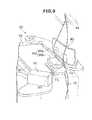
- the surface of the receiving member 62 is flat, and because the compressed air strikes obliquely on this surface, as shown in FIG. 9 , an air current that is substantially laminar can be easily formed near the surface of the receiving member 62. Accordingly, the spun yarn 10 upstream of the second slit 16 is effectively pushed toward the back side in a direction that is substantially parallel to the second slit 16 because of the air current flowing on the surface of the receiving member 62, and in this process, the spun yarn 10 is elongated and expanded. As a result, it is possible to suitably absorb the slack of the spun yarn 10 that was generated by the bending of the spun yarn 10 during the yarn joining work.
- the amount of the slack of the yarn may differ depending on the situation.
- the slack of the spun yarn 10 is removed by pushing the spun yarn 10 with the injected air. Therefore, regardless of the amount of the slack, it is possible to flexibly remove the slack of the yarn.
- the configuration is not limited to the one in which the air injecting device 61 and the receiving member 62 are mounted on the yarn joining device 20, and they can be arranged at a desired position in the spinning unit 1 downstream of the yarn-route guiding member 74 but upstream of the yarn joining device 20.
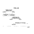
- the carrier controlling section causes the air injecting device 61 to start injection of the compressed air after the start of the yarn joining operation but before the completion of the yarn joining operation.
- the timing of starting the injection of the compressed air is before the clamping members 96 release the hold on the spun yarn 10.
- the slack of the spun yarn 10 can be absorbed by the action of the air current injected by the air injecting device 61.
- the slack of the spun yarn 10 can be suitably removed before it propagates to the yarn pooling device 7 on the upstream (or downstream) side. Because the slack of the spun yarn 10 is removed by pushing the spun yarn 10 with the air current, winding of the spun yarn 10 can be started smoothly, without exerting any resistance on the running of the joined spun yarn 10.
- the timing at which the air injecting device 61 starts the injection of the air can be set to a desired time point that is after the start of the yarn joining operation (after the clamping members 96 have started the hold) but before the clamping members 96 have released the hold. However, from the viewpoint of energy saving, it is preferable to start the injection at a timing immediately before the clamping members 96 release the hold.
- the injection of the air by the air injecting device 61 is stopped after the winding by the winding device 8 has started.
- the timing of stopping the injection of the air can be any desirable timing as long as it is after the disappearance of the slack of the spun yarn 10 in the portion which has been pushed by the air current accompanying the resumption of the winding by the winding device 8.
- the injection of the air can be stopped when a desired condition is satisfied, for example, when a predetermined time has elapsed from the start of the winding of the spun yarn 10, or when the rotational speed of the package 82 has reached a predetermined speed.
- the slack of the spun yarn 10 in the portion which has been pushed by the air current disappears. Because the spun yarn 10 is pushed by using only the air current, and not by using a mechanical part, possibility of yarn breakage is almost nil.
- the duration of time for which the air is to be injected by the air injecting device 61 can be changed depending on spinning conditions (e.g., a yarn count of the spun yarn to be formed by the spinning).
- the yarn joining device 20 includes the yarn joining section 25 and the air injecting device 61.
- the yarn joining section 25 performs the yarn joining on the spun yarn 10 that has been held in the bent state.
- the air injecting device 61 removes the slack of the spun yarn 10 positioned on the yarn joining path, which passes through the yarn joining section 25, by applying a force on the spun yarn 10 upstream of the yarn joining section 25.
- the spinning machine 100 includes the spinning device 6, the yarn pooling device 7, the winding device 8, the yarn joining section 25, the yarn-route guiding member 74, and the air injecting device 61.
- the spinning device 6 spins the fiber bundle 11 and forms the spun yarn 10.
- the yarn pooling device 7 pools the spun yarn 10 formed by the spinning device 6.
- the winding device 8 winds the spun yarn 10 from the yarn pooling device 7 and forms the package 82.
- the yarn joining section 25, at a position between the spinning device 6 and the yarn pooling device 7, performs the yarn joining on the spun yarn 10 that has been held in the bent state.
- the yarn-route guiding member 74 guides the spun yarn 10 downstream of the yarn pooling device 7 in the yarn path of the spun yarn 10.
- the air injecting device 61 removes the slack of the spun yarn 10 positioned on the yarn joining path, which passes through the yarn joining section 25, by applying a force on the spun yarn 10 in a region upstream of the yarn joining section 25 but downstream of the yarn-route guiding member 74.
- the slack of the spun yarn 10 which occurs when the spun yarn 10 that was held in the bent state is released, can be removed by the air injecting device 61. Accordingly, an influence of the slack of the spun yarn 10 on devices (particularly, on the yarn pooling device 7) upstream or downstream of the yarn joining section 25 can be avoided. Accordingly, after performing the yarn joining, winding of the spun yarn 10 can be resumed smoothly in the spinning machine 100.
- the air injecting device 61 applies a force on the spun yarn 10 by injecting air on the spun yarn 10.
- the slack of the spun yarn 10 can be removed by pushing the spun yarn 10 with the injected air. Furthermore, because the slack of the spun yarn 10 is removed by applying the force of the air current on the spun yarn 10, even if the amount of the slack of the spun yarn 10 varies depending on the circumstances, the slack of the spun yarn 10 can be flexibly removed without causing yarn breakage or the like.
- the joining device 20 and the spinning machine 100 further include the receiving member 62 that receives the air injected by the air injecting device 61.
- the air injecting device 61 is arranged on one side and the receiving member 62 is arranged on the other side of the yarn joining path.
- the air injecting device 61 and the receiving member 62 do not interfere with the spun yarn 10.
- the slack of the spun yarn 10 can be suitably removed by the action of air current, formed as a result of receiving the air at the receiving member 62, on the spun yarn 10.
- the receiving member 62 is a plate-shaped member.
- the air injecting device 61 injects the air on the spun yarn 10 from the nozzles 63 that are oriented obliquely to the receiving member 62.
- the air injected by the air injecting device 61 strikes obliquely on the plate-shaped receiving member 62, a laminar air current can be easily formed near the surface of the receiving member 62. Therefore, because it is possible to push the spun yarn 10 with the air current so as to elongate and expand, the slack of the spun yarn 10 can be more appropriately removed without causing defects such as warping in the spun yarn 10. Because the receiving member 62 has a simple shape, it is possible to reduce the manufacturing cost.
- the joining device 20 and the spinning machine 100 according to the present embodiment further includes the guiding plates 92 that guide the spun yarn 10 toward the yarn joining path.
- the air injecting device 61 is fixed to the guiding plates 92.
- the air current generated by the air injecting device 61 can be reliably applied to the spun yarn 10 positioned in the yarn joining path (more specifically, the spun yarn 10 positioned in the second slit 16 formed in the upstream guiding plate 92). Because it is not necessary to specifically prepare a place for fixing the air injecting device 61, the yarn joining device 20 (the spinning machine 100) can be configured in a rational and compact manner.
- the yarn pooling device 7 includes the yarn pooling roller 71 and the yarn hooking member 72.
- the yarn pooling roller 71 temporarily pools the spun yarn 10 by winding around the outer circumferential surface thereof.
- the spun yarn 10 drawn from the yarn pooling roller 71 is hooked on the yarn hooking member 72.
- the air injecting device 61 Because the slack of the spun yarn 10 that occurs during the yarn joining can be removed by the air injecting device 61, interruption of the winding that may happen by release of the spun yarn 10 from the yarn hooking member 72 due to the presence of the slack of the spun yarn 10 can be prevented. Accordingly, the winding of the joined spun yarn 10 can be resumed further smoothly.
- the air injecting device 61 starts the injection of the air after the start of the yarn joining operation by the yarn joining section 25 but before the completion of the yarn joining operation.
- the air current can be applied on the spun yarn 10 from a point in time before the completion of the yarn joining operation, the slack of the spun yarn 10 can be reliably removed before the slack of the spun yarn 10 generated during the yarn joining propagates to the upstream yarn pooling device 7.
- the yarn joining section 25 further includes the clamping members 96 capable of switching between a state in which the spun yarn 10 is held and a state in which the spun yarn 10 is released.
- the air injecting device 61 starts the injection of the air before the clamping members 96 release the hold on the spun yarn 10.
- the slack of the spun yarn 10 can be further reliably removed before the slack of the spun yarn 10 generated during the yarn joining propagates to the upstream yarn pooling device 7.
- the yarn ends of the spun yarn 10 are joined with a yarn joining method explained below.
- This yarn joining method includes a yarn holding step, a yarn joining step, and a yarn slack removing step.
- the spun yarn 10 is held in a bent state.
- the yarn ends of the spun yarn 10 are joined by the yarn joining section 25.
- the yarn slack removing step which is performed after the yarn holding step, the slack of the spun yarn 10 that was generated by the bending of the spun yarn 10 in the yarn holding step is removed on the upstream side of the yarn joining section 25.
- the slack of the spun yarn 10 which occurred when the spun yarn 10 that was held in the bent state is released, is removed at the yarn slack removing step. Accordingly, an influence of the slack of the spun yarn 10 on devices upstream or downstream of the yarn joining section 25 can be avoided. Accordingly, the winding and the like of the spun yarn 10 can be performed smoothly after performing the yarn joining.
- a yarn joining device 20 according to a second embodiment of the present invention is explained below with reference to FIG. 11 .
- elements that are identical or similar to those of the above-explained embodiment are indicated by the same reference symbols in the drawings and redundant explanation thereof is omitted.
- a yarn shifting device 61x is used as a yarn slack removing section to remove the slack of the spun yarn 10.
- the yarn shifting device 61x includes an electric motor 610, a shaft member 611, and a rod-shaped member 612.
- the electric motor 610 rotationally drives the shaft member 611.
- the rod-shaped member 612 is an elongated cylindrical member with one end fixed to the shaft member 611.
- a spring 613 which is a thin and elongated coil, is arranged near the portion where the rod-shaped member 612 is connected to the shaft member 611.
- the spring 613 has a linear shape when not deformed, but deforms by bending when a certain force is applied to the rod-shaped member 612.
- the electric motor 610 causes the rod-shaped member 612 to retract to a not-shown position.
- the electric motor 610 causes the rod-shaped member 612 to move from a position represented with a solid line to a position represented with a chain line at a timing that is immediately before the clamping members 96 release the clamp on the spun yarn 10. Because of this, the slack of the spun yarn 10 can be removed on the upstream side of the yarn joining section 25 by pushing the spun yarn 10 with the rod-shaped member 612 to the back side from the yarn joining path.
- the stroke with which the rod-shaped member 612 is rotated by the electric motor 610 in order to shift the spun yarn 10 by being in contact with the spun yarn 10 is constant, the amount of the slack of the spun yarn 10 may vary as explained above.
- the force that acts on the rod-shaped member 612 as a counterforce due to pushing of the spun yarn 10 by the rod-shaped member 612 becomes large, the spring 613 that is in the linear state appropriately deforms, whereby the rod-shaped member 612 is practically pushed back. Accordingly, because it is possible to press the spun yarn 10 by the rod-shaped member 612 with an appropriate force regardless of the size of the slack of the spun yarn 10, it is possible to avoid yarn breakage and the like.
- the electric motor 610 rotates in a reverse direction at a suitable timing whereby the rod-shaped member 612 releases the pushing state of the spun yarn 10.
- the slack of the spun yarn 10 in the portion that was pushed by the rod-shaped member 612 disappears, and the spun yarn 10 may push back the rod-shaped member 612.
- the spring 613 deforms in response to the pushing back of the rod-shaped member 612 by the spun yarn 10, no yarn breakage occurs in the part of the rod-shaped member 612.
- the amount by which the rod-shaped member 612 shifts the spun yarn 10 is automatically adjusted by the spring 613 depending on the tension applied on the spun yarn 10. Therefore, when compared with the configuration of the Patent Document 2, the configuration of the present embodiment enables reduction in the resistance against the running of the spun yarn 10 at the time of resumption of the winding of the spun yarn 10 by the winding device 8.
- the yarn shifting device 61x contacts the spun yarn 10 and shifts the spun yarn 10 from the yarn joining path.
- a simple configuration for removing the slack of the spun yarn 10 can be realized. Because the configuration involves removing the slack by making the rod-shaped member 612 contact with the spun yarn 10, the slack of the spun yarn 10 can be surely removed and the movement of the spun yarn 10 becomes stable.
- the configuration is not limited to the one in which the air injecting device 61 or the yarn shifting device 61x is arranged in the yarn joining device 20, and the air injecting device 61 or the yarn shifting device 61x can be arranged in the spinning unit 1 as far as it is arranged upstream of the yarn joining section 25 but downstream of the yarn-route guiding member 74.
- the air injecting device 61 can be attached to a casing of a not-shown waxing device arranged downstream of the yarn-route guiding member 74 of the spinning unit 1.
- the configuration is not limited to the one in which the yarn joining device 20 is arranged in the yarn joining carrier 2, and one yarn joining device can be arranged in each of the spinning units 1.
- the spinning machine 100 can include, instead of the spinning unit 1 having a configuration shown in the FIG. 2 , a spinning unit that winds, with respect to a height direction, on an upper side the spun yarn spun on a lower side.
- the positional relationship between the air injecting device 61 and the receiving member 62 is not limited to the one shown in FIG. 5 and the like.
- the air injecting device 61 and the receiving member 62 can be arranged such that the air injected by the air injecting device 61 directly strikes the receiving member 62.
- the air can be injected parallel to the receiving member 62.
- the positional relationship between the air injecting device 61 and the receiving member 62 with respect to the yarn joining path can be interchanged.
- the receiving member 62 can be omitted.
- the receiving member 62 is a plate-shaped member, and the receiving member 62 can be, for example, a block-shaped member.
- the end on the front side of the receiving member 62 can be formed straight instead of bending it.
- the configuration of the yarn shifting device 61x can be changed so that the spring is arranged inside the shaft member 611.
- the spring 613 can be omitted, and instead, elasticity can be imparted to the entire rod-shaped member 612.
- the configuration in which the rod-shaped member 612 (the shaft member 611) is driven with the electric motor 610 can be replaced with a configuration in which the rod-shaped member 612 (the shaft member 611) is driven with the cam that is used to drive the yarn shifting lever 93 and the like.
- a yarn trap that removes the slack of the spun yarn 10 by sucking the spun yarn 10 can be arranged instead of the air injecting device 61 and the yarn shifting device 61x.
- the yarn joining device 20 (the yarn joining section 25) can be of any type as long as it performs the yarn joining in a state in which the spun yarn 10 is held in a bent state.
- the splicer-type yarn joining device (the yarn joining section) can be replaced with a mechanical knotter.
- a yarn joining device includes a yarn joining section and a yarn slack removing section.
- the yarn joining section performs yarn joining in a state in which a yarn is held in a bent state.
- the yarn slack removing section removes slack of the yarn positioned on a yarn joining path that passes through the yarn joining section by applying a force on the yarn upstream of the yarn joining section.
- the yarn slack removing section includes an air injecting device that injects air on the yarn.
- the slack of the yarn can be removed by pushing the yarn with the injected air. Furthermore, because the slack of the yarn is removed by applying the force of air current on the yarn, even if the amount of the slack of the yarn varies depending on the circumstances, the slack of the yarn can be flexibly removed without causing yarn breakage or the like.
- the yarn joining device further includes a receiving member that receives the air injected by the air injecting device. Moreover, it is preferable that the air injecting device is arranged on one side and the receiving member is arranged on other side of the yarn joining path.
- the air injecting device and the receiving member do not interfere with the yarn.
- the slack of the yarn can be suitably removed by the action of air current, formed as a result of receiving the air at the receiving member, on the yarn.
- the receiving member is a plate-shaped member, and that the air injecting device injects the air on the yarn from an air injection hole that is arranged obliquely to the receiving member.
- the air injected by the air injecting device strikes obliquely on the plate-shaped receiving member, a laminar air current can be easily formed near the surface of the receiving member. Therefore, because it is possible to push the yarn with the air current so as to elongate and expand, the slack of the yarn can be more appropriately removed without causing defects such as warping in the yarn. Because the receiving member has a simple configuration, it is possible to reduce the manufacturing cost.
- the yarn joining device further includes a yarn guiding member that guides the yarn to the yarn joining path, and that the air injecting device is fixed to the yarn guiding member.
- the air current generated by the air injecting device can be reliably applied to the yarn positioned in the yarn joining path. Moreover, because it is not necessary to specifically prepare a place for fixing the air injecting device, the yarn joining device can be configured in a rational and compact manner.
- the yarn slack removing section can include a yarn shifting device that comes in contact with the yarn and shifts the yarn from the yarn joining path.
- the configuration of the yarn slack removing section can be simplified. Moreover, because the configuration involves removing the slack by making the yarn slack removing section contact with the yarn, the slack of the yarn can be surely removed and the movement of the yarn becomes stable.
- a yarn winding machine includes a spinning device, a yarn pooling device, a winding device, a yarn joining section, a yarn-route guiding member, and a yarn slack removing section.
- the spinning device forms a yarn by spinning.
- the yarn pooling device pools the yarn formed by the spinning device.
- the winding device winds the yarn from the yarn pooling device and forms a package.
- the yarn joining section performs yarn joining at a position between the spinning device and the winding device in a state in which the yarn is held in a bent state.
- the yarn-route guiding member guides the yarn on a downstream side of the yarn pooling device in a yarn route of the yarn.
- the yarn slack removing section removes slack of the yarn positioned on a yarn joining path that passes through the yarn joining section by applying a force on the yarn upstream of the yarn joining section but downstream of the yarn-route guiding member.
- the yarn pooling device includes a yarn pooling roller and a yarn hooking member. It is preferable that the yarn pooling roller pools the yarn by being wound around an outer circumferential surface thereof. It is preferable that the yarn hooking member hooks the yarn that is pulled from the yarn pooling roller.
- the slack of the yarn that occurs during the yarn joining can be removed by the yarn slack removing section, interruption of the winding that may happen by release of the yarn from the yarn hooking member due to the presence of the slack of the yarn can be prevented. Accordingly, the winding of the joined yarn can be resumed further smoothly.
- the yarn slack removing section includes an air injecting device that injects air on the yarn.
- the slack of the yarn can be removed by pushing the yarn with the injected air. Furthermore, because the slack of the yarn is removed by applying the force of the air current on the yarn, even if the amount of the slack of the yarn varies depending on the circumstances, the slack of the yarn can be flexibly removed.
- the yarn winding machine further includes a receiving member that receives the air injected by the air injecting device.
- the air injecting device is arranged on one side and the receiving member is arranged on other side of the yarn joining path.
- the air injecting device and the receiving member do not interfere with the yarn.
- the slack of the yarn can be suitably removed by the action of air current, formed as a result of receiving the air at the receiving member, on the yarn.
- the yarn winding machine further includes a yarn guiding member that guides the yarn to the yarn joining section. Moreover, it is preferable that the air injecting device is fixed to the yarn guiding member.
- the air current generated by the air injecting device can be reliably applied to the yarn positioned in the yarn joining path. Moreover, because it is not necessary to specifically prepare a place for fixing the air injecting device, the yarn winding machine (surrounding the yarn joining section) can be configured in a rational and compact manner.
- the air injecting device injects the air after the yarn joining section has started a yarn joining operation but before the yarn joining operation is completed.
- the air current can be applied on the yarn from a point in time before the completion of the yarn joining operation, the slack of the yarn can be reliably removed before the slack of the yarn generated during the yarn joining operation propagates to the upstream yarn pooling device.
- the yarn joining section includes a clamping member capable of switching between a state where the clamping member holds the yarn and a state where the clamping member releases the hold on the yarn. Moreover, the air injecting device starts injection of the air before the clamping member releases the hold on the yarn.
- the air current can be applied on the yarn from a point in time before the clamping member releases the hold on the yarn, the slack of the yarn can be further reliably removed before the slack of the yarn generated during the yarn joining operation propagates to the upstream yarn pooling device.
- a yarn joining method includes holding, joining, and removing.
- the holding includes holding a yarn in a bent state.
- the joining includes joining yarn ends of the yarn by using a yarn joining section.
- the removing includes removing, after completion of the holding, slack of the yarn that was generated by bending of the yarn in the holding on upstream side of the yarn joining section.
Landscapes
- Spinning Or Twisting Of Yarns (AREA)
- Tension Adjustment In Filamentary Materials (AREA)
Abstract
Description
- The present invention generally relates to a yarn joining device having a yarn joining section that joins yarn ends of a yarn, a yarn winding machine, and a yarn joining method.
- Yarn winding machines that include a yarn joining section that makes a discontinuous yarn continuous are known in the art.
-
Japanese Patent Application Laid-open No. 2000-290839 -
Japanese Patent Application Laid-open No. 2013-067475 Japanese Patent Application Laid-open No. 2000-290839 - When the yarn joining is performed in a state in which the yarn is bent as disclosed in
Japanese Patent Application Laid-open No. 2013-067475 - It is an object of the present invention to provide a yarn joining device, a yarn winding machine, and a yarn joining method capable of reliably removing the yarn slack generated during the yarn joining.
- This object is achieved by a yarn joining device as claimed in claim 1, by a yarn winding machine as claimed in
claim 9, and a yarn joining method as claimed inclaim 11. - According to an aspect of the present invention, a yarn joining device includes a yarn joining section that performs yarn joining in a state in which a yarn is held in a bent state; and a yarn slack removing section that removes slack of the yarn positioned on a yarn joining path that passes through the yarn joining section by applying a force on the yarn upstream of the yarn joining section.
- According to another aspect of the present invention, a yarn winding machine includes a spinning device that forms a yarn by spinning; a yarn pooling device that pools the yarn formed by the spinning device; a winding device that winds the yarn from the yarn pooling device and forms a package; a yarn joining section that performs yarn joining at a position between the spinning device and the winding device in a state in which the yarn is held in a bent state; a yarn-route guiding member that guides the yarn on a downstream side of the yarn pooling device in a yarn route of the yarn; and a yarn slack removing section that removes slack of the yarn positioned on a yarn joining path that passes through the yarn joining section by applying a force on the yarn upstream of the yarn joining section but downstream of the yarn-route guiding member.
- According to still another aspect of the present invention, a yarn joining method of joining yarn ends includes holding a yarn in a bent state; joining the yarn ends by using a yarn joining section; and removing, after completion of the holding, slack of the yarn that was generated by bending of the yarn in the holding on upstream side of the yarn joining section. The above and other objects, features, advantages and technical and industrial significance of this invention will be better understood by reading the following detailed description of presently preferred embodiments of the invention, when considered in connection with the accompanying drawings.
- The above and other objects, features, advantages and technical and industrial significance of this invention will be better understood by reading the following detailed description of presently preferred embodiments of the invention, when considered in connection with the accompanying drawings.
-
-
FIG. 1 is a schematic front view showing an overall structure of a spinning machine including a yarn joining device according to a first embodiment of the present invention. -
FIG. 2 is a side view of a spinning unit and a yarn joining carrier. -
FIG. 3 is a side view showing a state in which a spun yarn is caught by sucking by a yarn catching section of the yarn joining carrier. -
FIG. 4 is a side view showing a state in which the spun yarn is guided to a yarn joining section by the yarn catching section of the yarn joining carrier. -
FIG. 5 is a perspective view of the yarn joining device when seen from obliquely above. -
FIG. 6 is a side cross-sectional view showing a state in which the yarn is held by a clamping member of the yarn joining device. -
FIG. 7 is a side cross-sectional view showing a state in which the yarn is untwisted in the yarn joining device. -
FIG. 8 is a side cross-sectional view showing a state in which yarn ends are twisted together in the yarn joining device. -
FIG. 9 is a perspective view showing a state in which yarn slack is removed by an air injecting device and a receiving member. -
FIG. 10 is a view for explaining an injection timing at which compressed air is injected by the air injecting device. -
FIG. 11 is a perspective view showing a state in which yarn slack is removed by a yarn shifting device included in a yarn joining device according to a second embodiment of the present invention. - Exemplary embodiments of a spinning machine (spinning frame) 100 including a
yarn joining device 20 according to a first embodiment of the present invention will be explained below with reference to the accompanying drawings. Thespinning machine 100 shown inFIG. 1 includes plural spinning units (yarn winding units) 1 arranged side by side, ayarn joining carrier 2, ablower box 3, and amotor box 4. In this specification, the terms "upstream" and "downstream" refer to the upstream and the downstream in a travelling direction of afiber bundle 11 or aspun yarn 10 when thespun yarn 10 is formed and wound in the spinning unit 1. - The
motor box 4 is arranged on one side in the direction in which the plural spinning units 1 are arranged and it houses a common driving source for the spinning units 1. Theblower box 3 is arranged on the other side in the direction in which the plural spinning units 1 are arranged and the other side is the opposite side of the side on which themotor box 4 is arranged. A blower is housed inside theblower box 3. The blower functions as a negative pressure source that supplies the negative pressure to each of the spinning units 1 and theyarn joining carrier 2. A compressor that functions as a compressed air source that supplies compressed air to each of the spinning units 1 and theyarn joining carrier 2 is arranged at a suitable location separated from thespinning machine 100. The compressed air is supplied from the compressor to thespinning machine 100 via one or more air pipes. One or more regulators that adjust an air pressure of the compressed air are arranged in theblower box 3 or themotor box 4. The compressed air to be supplied to thespinning machine 100 via the air pipes is supplied to each of the spinning units 1 and theyarn joining carrier 2 through the regulators. The method of supplying the compressed air to the spinning units 1 and theyarn joining carrier 2 is not limited to the one explained here. - The spinning unit 1 is configured as an air spinning unit that performs spinning by applying twists to the
fiber bundle 11 by the action of a swirling air current. As shown inFIG. 2 , each of the spinning units 1 mainly includes, sequentially arranged from upstream to downstream, adrafting device 5, aspinning device 6, ayarn pooling device 7, and awinding device 8. In each of the spinning units 1, thefiber bundle 11 conveyed from thedrafting device 5 is spun by thespinning device 6 thereby forming thespun yarn 10, and thespun yarn 10 is wound around abobbin 81 by thewinding device 8 thereby forming apackage 82. - The
drafting device 5 includes, sequentially from the upstream, four drafting rollers, namely, aback roller 51, a third roller 52, amiddle roller 54 with a rubber apron belt 53 stretched thereover, and afront roller 55. Each of the drafting rollers is rotationally driven at a predetermined rotation speed. Moreover, thedrafting device 5 includes an opposing roller arranged facing each of the drafting rollers. Thedrafting device 5 transports asliver 12, which is the raw material of thefiber bundle 11, by nipping thesliver 12 between the drafting rollers and the opposing rollers thereby forming thefiber bundle 11 by stretching (drafting) thesliver 12 until a predetermined width is obtained. - The
spinning device 6 is located downstream of thedrafting device 5 and forms thespun yarn 10 by applying twists to thefiber bundle 11 supplied from thedrafting device 5. A device that applies twists to thefiber bundle 11 by using a swirling air current is employed as thespinning device 6 in the present embodiment. - The
yarn pooling device 7 is arranged between thespinning device 6 and thewinding device 8. Theyarn pooling device 7 includes ayarn pooling roller 71, ayarn hooking member 72, and anelectric motor 73. Theelectric motor 73 can rotationally drive theyarn pooling roller 71. Theyarn pooling device 7 functions as a kind of a buffer that temporarily pools thespun yarn 10 at a position between thespinning device 6 and thewinding device 8. - The
yarn pooling roller 71 is configured so as to temporarily pool thespun yarn 10 by winding a certain amount of thespun yarn 10 on an outer circumferential surface thereof. Theyarn hooking member 72 that can hook thespun yarn 10 is mounted on a downstream end portion of theyarn pooling roller 71. Theyarn hooking member 72 is supported in a rotatable manner relatively to theyarn pooling roller 71. - A permanent magnet is attached to any one of the
yarn hooking member 72 and theyarn pooling roller 71, and a magnetic hysteresis member is attached to the other of theyarn hooking member 72 and theyarn pooling roller 71. These magnetic means generate a torque against a relative rotation of theyarn hooking member 72 with respect to theyarn pooling roller 71. Therefore, only when a force exceeding this torque is applied on the yarn hooking member 72 (i.e., when a tension of a predetermined amount or larger is applied to the spun yarn 10), theyarn hooking member 72 is rotated relatively to theyarn pooling roller 71 whereby the spunyarn 10 wound around theyarn pooling roller 71 can be unwound. On the other hand, when such a force is not applied to theyarn hooking member 72, theyarn pooling roller 71 and theyarn hooking member 72 are integrally rotated whereby the spunyarn 10 that has been wound around theyarn pooling roller 71 is not unwound. The spunyarn 10 is pooled on theyarn pooling roller 71 when theyarn pooling roller 71 rotates. - In this manner, the
yarn pooling device 7 operates such that the unwinding amount of the spunyarn 10 increases when the yarn tension on the downstream side increases, and the unwinding amount of the spunyarn 10 decreases when the yarn tension decreases (when the spunyarn 10 is about to slacken). With this operation, theyarn pooling device 7 absorbs the slack of the spunyarn 10 and can apply an appropriate tension on the spunyarn 10 at any given time during the yarn winding. Furthermore, because theyarn hooking member 72 operates to absorb any variation of the tension applied on the spunyarn 10 between theyarn pooling device 7 and the windingdevice 8, the variation of the tension is prevented from affecting the spunyarn 10 between theair spinning device 6 and theyarn pooling device 7. - A yarn-
route guiding member 74 that guides to the downstream side the spunyarn 10 pulled from theyarn pooling device 7 is arranged downstream of theyarn pooling device 7. - The yarn-
route guiding member 74 guides the spunyarn 10, which is pulled out from an axial end of the outer circumferential surface of theyarn pooling roller 71, such that the spunyarn 10 passes over a line that extends from a rotation axis of theyarn pooling roller 71. Accordingly, when theyarn hooking member 72 is rotating in a state in which it has hooked the spunyarn 10, a substantiallyconical balloon 75 is formed between theyarn pooling roller 71 and the yarn-route guiding member 74 because of the revolving of the spunyarn 10. - The winding
device 8 forms thepackage 82 by winding the spunyarn 10 around thebobbin 81 while traversing the spunyarn 10. The windingdevice 8 includes acradle arm 83 and a windingdrum 84. - The
cradle arm 83 is rotatably supported by asupport shaft 86. Thecradle arm 83 is capable of rotatably supporting the bobbin 81 (or the package 82) around which the spunyarn 10 is to be wound. The windingdrum 84 is rotationally driven in a predetermined direction at a constant rotational speed. By rotating thecradle arm 83 with thesupport shaft 86 as a center, the outer circumferential surface of the supported bobbin 81 (or the package 82) can be brought into contact with or separated from the windingdrum 84. When the outer circumferential surface of the bobbin 81 (or the package 82) is brought into contact with the rotationally driven windingdrum 84, the bobbin 81 (or the package 82) is rotated following the rotation of the windingdrum 84 whereby the spunyarn 10 is wound on the circumferential surface of the bobbin 81 (or the package 82). - A traversing
device 85 includes a traversingguide 87 that can hook and guide the spunyarn 10. The traversingguide 87 is driven by a not-shown driving means to perform reciprocating movement in a direction that is parallel to the rotation axis of the windingdrum 84. With this configuration, when the traversingguide 87 with the spunyarn 10 hooked thereby is caused to make the reciprocating movement while the windingdrum 84 is rotating, the spunyarn 10 can be wound around thepackage 82 while traversing the spunyarn 10. - The winding
device 8 includes a not-shown brake mechanism that applies brake to the rotation of thepackage 82. The configuration of the brake mechanism is not particularly limited, and can include, for example, a brake shoe that contacts a member that integrally rotates with thepackage 82 and a pneumatic cylinder that presses the brake shoe to this member. - A yarn
quality monitoring device 9 that monitors the quality of the spunyarn 10 is arranged between the spinningdevice 6 and theyarn pooling device 7. The yarnquality monitoring device 9 monitors the state (thickness and the like) of the running spunyarn 10 by using an optical transmission-type sensor to detect a yarn defect (a place where there is an abnormality in the spun yarn 10) in the spunyarn 10. The sensor with which the yarnquality monitoring device 9 monitors the spunyarn 10 is not limited to the optical transmission-type sensor, and can, for example, be an electrostatic capacitance-type sensor. A foreign matter included in the spunyarn 10 can be detected as the yarn defect. - As shown in
FIGS. 1 and2 , theyarn joining carrier 2 includes theyarn joining device 20, a yarn catching section (asuction pipe 21 and a suction mouth 22), and areverse rotation mechanism 29. Theyarn joining carrier 2 includes a not-shown carrier controlling section that controls various components of theyarn joining carrier 2. - The
yarn joining device 20 includes ayarn joining section 25 that is constructed as a splicer device that forms a splicing point by applying twists to the yarn ends by the swirling air current. - In the following explanation, the side of the
yarn joining device 20 and theyarn joining section 25 closer to a yarn route, which is a running path of the spunyarn 10, shall be referred to as a front side and the side that is far from the yarn path shall be referred to as a far side. Furthermore, the direction that extends from the front side to the far side, or vice versa, of theyarn joining device 20 or theyarn joining section 25 shall be referred to as a front-back direction. - As shown in
FIG. 3 , each of thesuction pipe 21 and thesuction mouth 22 is rotatable in the vertical direction about a corresponding axis. Each of thesuction pipe 21 and thesuction mouth 22 can catch a yarn end by suction by generating a suction air current at tip ends thereof. - Specifically, as shown in
FIG. 3 , the carrier controlling section rotates thesuction pipe 21 and also generates a suction air current at the tip end thereof. Accordingly, thesuction pipe 21 catches by suction the yarn end of the spun yarn 10 (the spun yarn 10) supplied from thespinning device 6. Simultaneously, the carrier controlling section rotates thesuction mouth 22 and also generates a suction air current at the tip end thereof. Accordingly, thesuction mouth 22 catches by suction the yarn end of the spun yarn 10 (the spun yarn 10) from thepackage 82. - Thereafter, as shown in
FIG. 4 , the carrier controlling section rotates thesuction pipe 21 and thesuction mouth 22. As a result, the yarn ends caught by thesuction pipe 21 and thesuction mouth 22 are guided to a region on the front side of the yarn joining section 25 (i.e., a region on the left side inFIG. 4 ). - Accordingly, the spun
yarn 10 from thepackage 82 and the spunyarn 10 from thespinning device 6 are set in a path (yarn joining path) where theyarn joining section 25 performs the yarn joining. In the following explanation, the spunyarn 10 from thespinning device 6 sucked and caught by thesuction pipe 21 is referred to as a first yarn, and the spunyarn 10 from thepackage 82 sucked and caught by thesuction mouth 22 is referred to as a second yarn. - The
reverse rotation mechanism 29 includes a supportingarm 30 that is approachable/ retractable toward the windingdevice 8 from theyarn joining carrier 2, and areverse rotation roller 31 supported on a tip end of the supportingarm 30. Thereverse rotation roller 31 can be rotationally driven by a not-shown electric motor in a direction that is opposite of the direction in which the windingdrum 84 rotates. - Subsequently, the detailed structure of the
yarn joining section 25 will be explained while referring toFIGS. 5 and6 .FIG. 5 shows a state when the yarn joining device 20 (yarn joining section 25) is seen from the upstream side. - As shown in
FIGS. 5 and6 , theyarn joining section 25 mainly includes ayarn joining nozzle 91, a pair of guidingplates 92, a pair of yarn shifting levers 93, a pair ofyarn pressing levers 94, a pair ofcutters 95, a pair of clampingmembers 96, and a pair of untwistingpipes 97. - The
yarn joining nozzle 91 is arranged on the front side of the yarn joining section 25 (i.e., on the side closer to the yarn path that is the running path of the spun yarn 10). Ayarn joining hole 98 through which the spunyarn 10 can pass is formed in theyarn joining nozzle 91. An injection port for passing the compressed air to be injected is formed inside theyarn joining hole 98. Theyarn joining nozzle 91 can generate a swirling air current inside theyarn joining hole 98 by injecting compressed air from the injection port inside theyarn joining hole 98. - For example, as shown in
FIG. 6 , one unit of each of the guidingplates 92, the yarn shifting levers 93, theyarn pressing levers 94, thecutters 95, the clampingmembers 96, and the untwistingpipes 97 is arranged on each of the upstream side and the downstream side of theyarn joining nozzle 91. - As shown in
FIG. 5 , two slits, afirst slit 15 and asecond slit 16, that open the front side of theyarn joining section 25, are formed side by side in each of the two guidingplates 92. The four slits formed in the two guidingplates 92 are parallel to each other. - When performing yarn joining of a disconnected spun
yarn 10 in theyarn joining section 25, the first yarn caught by thesuction pipe 21 is guided into thesecond slits 16 of the two guidingplates 92, and the second yarn caught by thesuction mouth 22 is guided into thefirst slits 15 of the two guidingplates 92. - By inserting the first yarn into the
second slits 16 and the second yarn into thefirst slits 15, the first yarn and the second yarn can be guided to positions at which the later-explainedyarn shifting leaver 93 is able to shift those yarns. In the present embodiment, the yarn joining path, which is the path of the spun yarn 10 (yarn end) where theyarn joining section 25 performs the yarn joining, is made to pass through theyarn joining section 25 from thesecond slits 16 in theupstream guiding plate 92. Thus, theupstream guiding plate 92 is a member that guides the spunyarn 10 to the yarn joining path. - The two yarn shifting levers 93 are rotatable simultaneously in two directions about an axis arranged on the side of the
yarn joining nozzle 91. The two directions are a direction (closing direction) from where the levers enter between the two guidingplates 92 and a direction (opening direction) from where the levers come out from between the two guidingplates 92.FIG. 5 shows a state in which the yarn shifting levers 93 have been rotated in the opening direction, andFIG. 6 shows a state in which the yarn shifting levers 93 have been rotated in the closing direction. - By rotating the yarn shifting levers 93 in the closing direction, the first yarn is pushed in the interior of the
second slits 16 and the second yarn is pushed in the interior of thefirst slits 15. By further rotating in the closing direction, as shown inFIG. 6 , the yarn shifting levers 93 can guide the first yarn and the second yarn into theyarn joining hole 98. - Because spaces are formed between the
yarn joining nozzle 91 and each of the guidingplates 92, each of the yarn shifting levers 93 enters into the corresponding space (toward the interior of the yarn joining section 25) when rotated in the closing direction. In this process, the first yarn and the second yarn shifted by the pair of the yarn shifting levers 93 are bent, as shown inFIG. 6 , in a V-shape in the spaces between theyarn joining nozzle 91 and each of the guidingplates 92. - The two
yarn pressing levers 94 are, as shown inFIG. 5 , simultaneously rotatable about an axis arranged near the rotation axis of the yarn shifting levers 93. Each of the twoyarn pressing levers 94, when theyarn joining nozzle 91 performs the yarn joining, rotates in the closing direction and respectively presses the first yarn and the second yarn thereby positioning the first yarn and the second yarn. - One
cutter 95 is arranged on a surface, which faces theyarn joining nozzle 91, of each of the two guidingplates 92. Each of thecutters 95 can cut the spunyarn 10. Specifically, thecutter 95 arranged on theupstream guiding plate 92 can cut the second yarn that has entered thefirst slits 15 and thecutter 95 arranged on the downstream guidingplate 92 can cut the first yarn that has entered thesecond slits 16. - One clamping
member 96 is arranged on a surface, which is on the opposite side of the surface that faces theyarn joining nozzle 91, of each of the two guidingplates 92. Each of the clampingmembers 96 includes amovable member 96a and anon-movable member 96b. One pair of themovable member 96a and thenon-movable member 96b is arranged across thefirst slits 15. Other pair of themovable member 96a and thenon-movable member 96b is arranged across thesecond slits 16. Themovable members 96a can be switched between a state in which they are pressed against and are in contact with thenon-movable members 96b and a state in which they are separated from thenon-movable members 96b. - Each of the clamping
members 96 clamps and holds the spunyarn 10, so that the spunyarn 10 does not move, by causing themovable member 96a to press against thenon-movable member 96b in a state in which the spunyarn 10 is sandwiched between themovable member 96a and thenon-movable member 96b. Specifically, the clampingmember 96 arranged on theupstream guiding plate 92 clamps and holds the first yarn that has entered thesecond slits 16. And, the clampingmember 96 arranged on the downstream guidingplate 92 clams and holds the second yarn that has entered thefirst slits 15. The hold on the spunyarn 10 can be released by causing themovable members 96a and thenon-movable members 96b to move apart. - Each of the two untwisting
pipes 97 is an elongated cylinder arranged such that the longitudinal direction thereof is parallel to the longitudinal direction of the other untwistingpipe 97 and also parallel to the front-back direction of theyarn joining section 25. The two untwistingpipes 97 are arranged side by side extending in a direction that is substantially parallel to the running direction of the yarn. One end of each of the untwistingpipes 97 opens in front of theyarn joining section 25. An air injection hole is formed in each of the untwistingpipes 97. By injecting compressed air inside the untwistingpipes 97 from the air injection holes, it is possible to generate an air current that flows toward the far end (an opposite end with respect to the yarn path) of each of the untwistingpipes 97. - The yarn shifting levers 93, the
yarn pressing levers 94, thecutters 95, the clampingmembers 96, and the like, for example, are caused to operate in conjunction with each other with a cam mechanism. Accordingly, the later-explained yarn joining work can be performed smoothly. - Subsequently, the yarn joining work performed by the
yarn joining device 20 will be explained while referring toFIGS. 3 to 8 . - When yarn breakage or yarn disconnection occurs in a particular spinning unit 1 due to some reason, first, the
package 82 is separated from the windingdrum 84, and the rotation of thepackage 82 is stopped by operating the brake mechanism. Furthermore, the spunyarn 10 that has been pooled on theyarn pooling roller 71 of the particular spinning unit 1 is completely removed by a not-shown removing device leading to a state in which no spunyarn 10 is present on theyarn pooling roller 71. - Then, the spinning unit 1 requests the
yarn joining carrier 2 to perform the yarn joining work. In response to this request, theyarn joining carrier 2 travels to the spinning unit 1 and stops. - When the
yarn joining carrier 2 arrives at the spinning unit 1, as shown inFIG. 3 , the carrier controlling section rotates thesuction pipe 21 and thesuction mouth 22 to respectively suck and catch the first yarn and the second yarn. - At this time, as shown in
FIG. 3 , the carrier controlling section causes thereverse rotation roller 31 of thereverse rotation mechanism 29 to come in contact with thepackage 82, and drives thereverse rotation roller 31 in the direction that is opposite of the direction in which the windingdrum 84 rotates. Accordingly, thepackage 82 is rotated in the opposite direction (which may be referred to as an unwinding direction in the below explanation) that is opposite of the winding direction that is the direction in which the bobbin 81 (or the package 82) is rotated when the spunyarn 10 is wound around the bobbin 81 (or the package 82). In this state, the spunyarn 10 presents on the surface of thepackage 82 is sucked with thesuction mouth 22 to draw the spunyarn 10 from thepackage 82. - After the
suction pipe 21 and thesuction mouth 22 have sucked and caught the spunyarn 10, as shown inFIG. 4 , the carrier controlling section causes thesuction pipe 21 and thesuction mouth 22 to rotate so that the caught first yarn and the caught second yarn are guided to the front side of theyarn joining section 25. - Thereafter, the yarn joining operation by the yarn joining section 25 (yarn joining device 20) is started. To be more specific, as shown in
FIG. 6 , theyarn joining section 25 causes the pair of the yarn shifting levers 93 to rotate and come in contact with the spunyarn 10 thereby inserting the spunyarn 10 into theyarn joining hole 98 of theyarn joining nozzle 91. Theyarn joining section 25, in the state shown inFIG. 6 , holds the spun yarn 10 (the first yarn and the second yarn) with the pair of the clampingmembers 96. - Substantially simultaneously with this, the rotation in the unwinding direction of the
package 82 by thereverse rotation roller 31 is stopped. Moreover, after the spunyarn 10 is held by the pair of the clampingmembers 96, the spun yarn 10 (first yarn) is hooked by a suitable means on theyarn hooking member 72 of theyarn pooling device 7, and pooling of the spunyarn 10 on theyarn pooling roller 71 is started. - Subsequently, the carrier controlling section starts injection of the compressed air into the pair of the untwisting
pipes 97. Accordingly, an air current that flows toward the back side of theyarn joining section 25 is generated inside each of the untwistingpipes 97 whereby a suction air current is generated at the opening of each of the untwistingpipes 97. Around this time, the carrier controlling section operates the pair of thecutters 95 and cuts the first yarn at a point between thesuction pipe 21 and theyarn joining section 25 and cuts the second yarn at a point between thesuction mouth 22 and theyarn joining section 25, respectively. The two yarn ends generated by these cuttings are sucked by the untwistingpipes 97 and drawn into the interior of the untwistingpipes 97. As shown inFIG. 7 , twists of each of the yarn ends are released by the action of the air current present inside each of the untwistingpipes 97. - When untwisting of each of the yarn ends is completed, the carrier controlling section stops the injection of the compressed air into each of the untwisting
pipes 97. Furthermore, the carrier controlling section, by further bending the spunyarn 10 by using the pair of the yarn shifting levers 93 and the pair of theyarn pressing levers 94, draws each of the untwisted yarns from each of the untwistingpipes 97. The two yarn ends drawn from the pair of the untwistingpipes 97 are set in theyarn joining hole 98 of theyarn joining nozzle 91, as shown inFIG. 8 , in mutually overlapping manner. While the first yarn and the second yarn have been held by the pair of theyarn pressing levers 94 in this manner, theyarn joining section 25 injects the compressed air into theyarn joining hole 98. As a result, a swirling current is generated in theyarn joining hole 98 whereby twists are applied to the fibers constituting each of the yarn ends. The yarn end of the first yarn and the yarn end of the second yarn are entangled by the twisting and a splicing point is formed. - The
yarn joining section 25 according to the present embodiment includes a not-shown splicing-point length adjusting device that can adjust a shifting amount (in other words, the degree of bending of the spunyarn 10 during the yarn joining work) by which the spunyarn 10 is to be shifted by the pair of the yarn shifting levers 93. The splicing-point length adjusting device can change the length of the splicing point by adjusting the length by which the yarn ends overlap in theyarn joining hole 98 by adjusting the shifting amount of the yarn shifting levers 93. - Once the splicing point is formed, the carrier controlling section stops the injection of the air into the
yarn joining hole 98. Furthermore, the carrier controlling section causes the hold on the spunyarn 10 by the pair of the clampingmembers 96 to be released, and causes the regulation of the yarn route by the pair of the yarn shifting levers 93 and the pair of theyarn pressing levers 94 to be released. With this, the yarn joining operation performed by theyarn joining section 25 is completed. - At about the same time, the outer circumferential surface of the
package 82 is made to contact with the rotating windingdrum 84. Accordingly, the rotation of thepackage 82 is started and the winding of the spunyarn 10 is resumed. - As explained above, when performing the yarn joining in the
yarn joining section 25, the spunyarn 10 is bent by using the pair of the yarn shifting levers 93 and the pair of the yarn pressing levers 94 (seeFIG. 6 ). When the bending is released after completion of the yarn joining work, the spunyarn 10 may slacken. - As explained above, at this point in time, the pooling of the spun
yarn 10 on theyarn pooling roller 71 has already been resumed. Accordingly, in the state in which the hold on the spunyarn 10 by the pair of the clampingmembers 96 has been released, if it is temporarily assumed that the slack propagates to the upstream, the spunyarn 10 greatly swings in a region between the yarn-route guiding member 74 and theyarn pooling roller 71 whereby theballoon 75 shown inFIG. 4 inflates in a radial direction thereof. - If the diameter of the
balloon 75 becomes excessively large because the slack that propagates from theyarn joining device 20 is large, for example, undesired situations where the spunyarn 10 comes off from theyarn hooking member 72, the spunyarn 10 wound around the outer circumferential surface of theyarn pooling roller 71 is disordered, or the balloon 75 (spun yarn 10) gets entangled with the nearby parts may occur. As a result, the winding of the spunyarn 10 may be interrupted. - The
yarn joining device 20 according to the present embodiment further includes, as shown inFIGS. 5 and6 , anair injecting device 61 and a receivingmember 62 arranged upstream of theyarn joining section 25. Theair injecting device 61 can inject the compressed air toward the spun yarn 10 (in other words, the spunyarn 10 present in the yarn joining path) that is passing through thesecond slit 16 formed in theupstream guiding plate 92. Accordingly, the spunyarn 10 on which the hold by the pair of the clampingmembers 96 has been released is pushed upstream of theyarn joining section 25 by a blow of the air current whereby the slack of the spunyarn 10 is removed so that it does not propagate further upstream. - This will be explained in detail below. The
air injecting device 61 is arranged on a surface, of the surfaces of the upstream guidingplate 92 among the two guidingplates 92 arranged in theyarn joining section 25, that faces on the opposite side of the side on which theyarn joining nozzle 91 is arranged. Anair pipe 64 is connected to theair injecting device 61, and theair pipe 64 is connected to a compressed air source. A not-shown electromagnetic valve is arranged between the compressed air source and theair injecting device 61, and by controlling opening and closing of this valve, the carrier controlling section can switch between supply and non-supply of the compressed air to theair injecting device 61. One or more nozzles (air injection holes) 63 are formed in theair injecting device 61. Compressed air can be injected from thenozzles 63 on the spunyarn 10 that is inserted in thesecond slits 16. As a result, a force of the air current acts on the portion (a portion upstream of the yarn joining section 25) of the spun yarn 10 (first yarn) upstream of thesecond slits 16. - The receiving
member 62 is arranged on the upstream clamping member among the two clampingmembers 96 of theyarn joining section 25. Specifically, the receivingmember 62 is supported by themovable member 96a of the upstream clampingmember 96. The receivingmember 62 and theair injecting device 61 are arranged so that thesecond slit 16 is located therebetween (in other words, the yarn joining path is located therebetween). In other words, theair injecting device 61 is arranged on one side and the receivingmember 62 is arranged on the other side of the yarn joining path (second slit 16). The receivingmember 62 and theair injecting device 61 are arranged such that, not only thesecond slit 16 is arranged therebetween, but both of thefirst slit 15 and thesecond slit 16 are arranged therebetween. - The receiving
member 62 is a plate-shaped member. The receivingmember 62 is arranged on themovable member 96a at a position close to thesecond slit 16 in theupstream guiding plate 92 and perpendicularly to theupstream guiding plate 92. Accordingly, the receivingmember 62 receives near thesecond slit 16 the majority of the compressed air injected by theair injecting device 61. When the spunyarn 10 inserted in thesecond slit 16 is pushed by the compressed air, the spunyarn 10 comes in contact with the receivingmember 62 and is guided by the receivingmember 62. - An end portion on the front side of the receiving
member 62 is bent suitably away from the open side of thesecond slit 16. Accordingly, it is possible to prevent the spunyarn 10 from getting hooked on the receivingmember 62 when entering thesecond slit 16. - In the
yarn joining device 20 according to the present embodiment, as shown inFIGS. 5 and9 , the direction of thenozzles 63 of theair injecting device 61 from which the compressed air is injected is inclined to the receiving member 62 (second slit 16), and the air injected from thenozzles 63 in the direction indicated with a chain-line arrow strikes obliquely on the receivingmember 62. With this configuration, the spunyarn 10 inserted into thesecond slit 16 and theair injecting device 61 do not interfere with each other. Moreover, the air that strikes on the receivingmember 62 can be diverted to the back side of theyarn joining device 20. - The surface of the receiving
member 62 is flat, and because the compressed air strikes obliquely on this surface, as shown inFIG. 9 , an air current that is substantially laminar can be easily formed near the surface of the receivingmember 62. Accordingly, the spunyarn 10 upstream of thesecond slit 16 is effectively pushed toward the back side in a direction that is substantially parallel to thesecond slit 16 because of the air current flowing on the surface of the receivingmember 62, and in this process, the spunyarn 10 is elongated and expanded. As a result, it is possible to suitably absorb the slack of the spunyarn 10 that was generated by the bending of the spunyarn 10 during the yarn joining work. - According to the present embodiment, as explained above, because the degree of bending of the spun
yarn 10 during the yarn joining can be adjusted by using the splicing-point length adjusting device, the amount of the slack of the yarn may differ depending on the situation. However, in the present embodiment, the slack of the spunyarn 10 is removed by pushing the spunyarn 10 with the injected air. Therefore, regardless of the amount of the slack, it is possible to flexibly remove the slack of the yarn. - The configuration is not limited to the one in which the
air injecting device 61 and the receivingmember 62 are mounted on theyarn joining device 20, and they can be arranged at a desired position in the spinning unit 1 downstream of the yarn-route guiding member 74 but upstream of theyarn joining device 20. - As shown in
FIG. 10 , the carrier controlling section causes theair injecting device 61 to start injection of the compressed air after the start of the yarn joining operation but before the completion of the yarn joining operation. Particularly, the timing of starting the injection of the compressed air is before the clampingmembers 96 release the hold on the spunyarn 10. Accordingly, at the moment the clampingmembers 96 release the hold on the spunyarn 10, the slack of the spunyarn 10 can be absorbed by the action of the air current injected by theair injecting device 61. As a result, the slack of the spunyarn 10 can be suitably removed before it propagates to theyarn pooling device 7 on the upstream (or downstream) side. Because the slack of the spunyarn 10 is removed by pushing the spunyarn 10 with the air current, winding of the spunyarn 10 can be started smoothly, without exerting any resistance on the running of the joined spunyarn 10. - The timing at which the
air injecting device 61 starts the injection of the air can be set to a desired time point that is after the start of the yarn joining operation (after the clampingmembers 96 have started the hold) but before the clampingmembers 96 have released the hold. However, from the viewpoint of energy saving, it is preferable to start the injection at a timing immediately before the clampingmembers 96 release the hold. - The injection of the air by the
air injecting device 61 is stopped after the winding by the windingdevice 8 has started. The timing of stopping the injection of the air can be any desirable timing as long as it is after the disappearance of the slack of the spunyarn 10 in the portion which has been pushed by the air current accompanying the resumption of the winding by the windingdevice 8. The injection of the air can be stopped when a desired condition is satisfied, for example, when a predetermined time has elapsed from the start of the winding of the spunyarn 10, or when the rotational speed of thepackage 82 has reached a predetermined speed. - As explained above, along with the resumption of the winding by the winding
device 8, the slack of the spunyarn 10 in the portion which has been pushed by the air current disappears. Because the spunyarn 10 is pushed by using only the air current, and not by using a mechanical part, possibility of yarn breakage is almost nil. The duration of time for which the air is to be injected by theair injecting device 61 can be changed depending on spinning conditions (e.g., a yarn count of the spun yarn to be formed by the spinning). - When the winding
device 8 starts winding the spunyarn 10, tension is applied to the spunyarn 10 between thepackage 82 and the yarn-route guiding member 74 whereby the spunyarn 10 naturally comes off thesecond slits 16. That is, the spunyarn 10 exits from the yarn joining section 25 (yarn joining path) and returns to the original yarn route (yarn route shown inFIG. 2 ). Thereafter, if there is a request from another spinning unit 1, the yarn joining carrier travels to and performs the yarn joining work in that spinning unit 1. - As explained above, the
yarn joining device 20 according to the present embodiment includes theyarn joining section 25 and theair injecting device 61. Theyarn joining section 25 performs the yarn joining on the spunyarn 10 that has been held in the bent state. Theair injecting device 61 removes the slack of the spunyarn 10 positioned on the yarn joining path, which passes through theyarn joining section 25, by applying a force on the spunyarn 10 upstream of theyarn joining section 25. - The spinning
machine 100 according to the present embodiment includes thespinning device 6, theyarn pooling device 7, the windingdevice 8, theyarn joining section 25, the yarn-route guiding member 74, and theair injecting device 61. Thespinning device 6 spins thefiber bundle 11 and forms the spunyarn 10. Theyarn pooling device 7 pools the spunyarn 10 formed by thespinning device 6. The windingdevice 8 winds the spunyarn 10 from theyarn pooling device 7 and forms thepackage 82. Theyarn joining section 25, at a position between the spinningdevice 6 and theyarn pooling device 7, performs the yarn joining on the spunyarn 10 that has been held in the bent state. The yarn-route guiding member 74 guides the spunyarn 10 downstream of theyarn pooling device 7 in the yarn path of the spunyarn 10. Theair injecting device 61 removes the slack of the spunyarn 10 positioned on the yarn joining path, which passes through theyarn joining section 25, by applying a force on the spunyarn 10 in a region upstream of theyarn joining section 25 but downstream of the yarn-route guiding member 74. - With this configuration, after performing the yarn joining in the
yarn joining section 25, the slack of the spunyarn 10, which occurs when the spunyarn 10 that was held in the bent state is released, can be removed by theair injecting device 61. Accordingly, an influence of the slack of the spunyarn 10 on devices (particularly, on the yarn pooling device 7) upstream or downstream of theyarn joining section 25 can be avoided. Accordingly, after performing the yarn joining, winding of the spunyarn 10 can be resumed smoothly in the spinningmachine 100. - In the
yarn joining device 20 and the spinningmachine 100 according to the present embodiment, theair injecting device 61 applies a force on the spunyarn 10 by injecting air on the spunyarn 10. - With this configuration, the slack of the spun
yarn 10 can be removed by pushing the spunyarn 10 with the injected air. Furthermore, because the slack of the spunyarn 10 is removed by applying the force of the air current on the spunyarn 10, even if the amount of the slack of the spunyarn 10 varies depending on the circumstances, the slack of the spunyarn 10 can be flexibly removed without causing yarn breakage or the like. - The joining
device 20 and the spinningmachine 100 according to the present embodiment further include the receivingmember 62 that receives the air injected by theair injecting device 61. Theair injecting device 61 is arranged on one side and the receivingmember 62 is arranged on the other side of the yarn joining path. - With this configuration, the
air injecting device 61 and the receivingmember 62 do not interfere with the spunyarn 10. The slack of the spunyarn 10 can be suitably removed by the action of air current, formed as a result of receiving the air at the receivingmember 62, on the spunyarn 10. - In the
yarn joining device 20 and the spinningmachine 100 according to the present embodiment, the receivingmember 62 is a plate-shaped member. Theair injecting device 61 injects the air on the spunyarn 10 from thenozzles 63 that are oriented obliquely to the receivingmember 62. - Accordingly, because the air injected by the
air injecting device 61 strikes obliquely on the plate-shaped receivingmember 62, a laminar air current can be easily formed near the surface of the receivingmember 62. Therefore, because it is possible to push the spunyarn 10 with the air current so as to elongate and expand, the slack of the spunyarn 10 can be more appropriately removed without causing defects such as warping in the spunyarn 10. Because the receivingmember 62 has a simple shape, it is possible to reduce the manufacturing cost. - The joining
device 20 and the spinningmachine 100 according to the present embodiment further includes the guidingplates 92 that guide the spunyarn 10 toward the yarn joining path. Theair injecting device 61 is fixed to the guidingplates 92. - Accordingly, the air current generated by the
air injecting device 61 can be reliably applied to the spunyarn 10 positioned in the yarn joining path (more specifically, the spunyarn 10 positioned in thesecond slit 16 formed in the upstream guiding plate 92). Because it is not necessary to specifically prepare a place for fixing theair injecting device 61, the yarn joining device 20 (the spinning machine 100) can be configured in a rational and compact manner. - In the spinning
machine 100 according to the present embodiment, theyarn pooling device 7 includes theyarn pooling roller 71 and theyarn hooking member 72. Theyarn pooling roller 71 temporarily pools the spunyarn 10 by winding around the outer circumferential surface thereof. The spunyarn 10 drawn from theyarn pooling roller 71 is hooked on theyarn hooking member 72. - Because the slack of the spun
yarn 10 that occurs during the yarn joining can be removed by theair injecting device 61, interruption of the winding that may happen by release of the spunyarn 10 from theyarn hooking member 72 due to the presence of the slack of the spunyarn 10 can be prevented. Accordingly, the winding of the joined spunyarn 10 can be resumed further smoothly. - In the spinning
machine 100 according to the present embodiment, theair injecting device 61 starts the injection of the air after the start of the yarn joining operation by theyarn joining section 25 but before the completion of the yarn joining operation. - With this configuration, because the air current can be applied on the spun
yarn 10 from a point in time before the completion of the yarn joining operation, the slack of the spunyarn 10 can be reliably removed before the slack of the spunyarn 10 generated during the yarn joining propagates to the upstreamyarn pooling device 7. - In the spinning
machine 100 according to the present embodiment, theyarn joining section 25 further includes the clampingmembers 96 capable of switching between a state in which the spunyarn 10 is held and a state in which the spunyarn 10 is released. Theair injecting device 61 starts the injection of the air before the clampingmembers 96 release the hold on the spunyarn 10. - With this configuration, the slack of the spun
yarn 10 can be further reliably removed before the slack of the spunyarn 10 generated during the yarn joining propagates to the upstreamyarn pooling device 7. - In the yarn joining device 20 (spinning machine 100) according to the present embodiment, the yarn ends of the spun
yarn 10 are joined with a yarn joining method explained below. This yarn joining method includes a yarn holding step, a yarn joining step, and a yarn slack removing step. At the yarn holding step, the spunyarn 10 is held in a bent state. At the yarn joining step, the yarn ends of the spunyarn 10 are joined by theyarn joining section 25. At the yarn slack removing step, which is performed after the yarn holding step, the slack of the spunyarn 10 that was generated by the bending of the spunyarn 10 in the yarn holding step is removed on the upstream side of theyarn joining section 25. - With this process, after performing the yarn joining in the
yarn joining section 25, the slack of the spunyarn 10, which occurred when the spunyarn 10 that was held in the bent state is released, is removed at the yarn slack removing step. Accordingly, an influence of the slack of the spunyarn 10 on devices upstream or downstream of theyarn joining section 25 can be avoided. Accordingly, the winding and the like of the spunyarn 10 can be performed smoothly after performing the yarn joining. - A
yarn joining device 20 according to a second embodiment of the present invention is explained below with reference toFIG. 11 . In the explanation of the present embodiment, elements that are identical or similar to those of the above-explained embodiment are indicated by the same reference symbols in the drawings and redundant explanation thereof is omitted. - In the
yarn joining device 20 according to the present embodiment, in place of theair injecting device 61 and the receivingmember 62, ayarn shifting device 61x is used as a yarn slack removing section to remove the slack of the spunyarn 10. - The
yarn shifting device 61x includes anelectric motor 610, ashaft member 611, and a rod-shapedmember 612. Theelectric motor 610 rotationally drives theshaft member 611. The rod-shapedmember 612 is an elongated cylindrical member with one end fixed to theshaft member 611. Aspring 613, which is a thin and elongated coil, is arranged near the portion where the rod-shapedmember 612 is connected to theshaft member 611. Thespring 613, has a linear shape when not deformed, but deforms by bending when a certain force is applied to the rod-shapedmember 612. - When inserting the first yarn and the second yarn in the
second slit 16 and thefirst slit 15 respectively in order to perform the yarn joining work by theyarn joining device 20, theelectric motor 610 causes the rod-shapedmember 612 to retract to a not-shown position. When theyarn joining section 25 completes the yarn joining operation, theelectric motor 610 causes the rod-shapedmember 612 to move from a position represented with a solid line to a position represented with a chain line at a timing that is immediately before the clampingmembers 96 release the clamp on the spunyarn 10. Because of this, the slack of the spunyarn 10 can be removed on the upstream side of theyarn joining section 25 by pushing the spunyarn 10 with the rod-shapedmember 612 to the back side from the yarn joining path. - In the present embodiment, although the stroke with which the rod-shaped
member 612 is rotated by theelectric motor 610 in order to shift the spunyarn 10 by being in contact with the spunyarn 10 is constant, the amount of the slack of the spunyarn 10 may vary as explained above. However, when the force that acts on the rod-shapedmember 612 as a counterforce due to pushing of the spunyarn 10 by the rod-shapedmember 612 becomes large, thespring 613 that is in the linear state appropriately deforms, whereby the rod-shapedmember 612 is practically pushed back. Accordingly, because it is possible to press the spunyarn 10 by the rod-shapedmember 612 with an appropriate force regardless of the size of the slack of the spunyarn 10, it is possible to avoid yarn breakage and the like. - After the winding of the spun
yarn 10 by the windingdevice 8 is resumed, theelectric motor 610 rotates in a reverse direction at a suitable timing whereby the rod-shapedmember 612 releases the pushing state of the spunyarn 10. Accompanying the start of winding of the spunyarn 10 by the windingdevice 8, the slack of the spunyarn 10 in the portion that was pushed by the rod-shapedmember 612 disappears, and the spunyarn 10 may push back the rod-shapedmember 612. However, in the present embodiment, because thespring 613 deforms in response to the pushing back of the rod-shapedmember 612 by the spunyarn 10, no yarn breakage occurs in the part of the rod-shapedmember 612. - In the present embodiment, the amount by which the rod-shaped
member 612 shifts the spunyarn 10 is automatically adjusted by thespring 613 depending on the tension applied on the spunyarn 10. Therefore, when compared with the configuration of thePatent Document 2, the configuration of the present embodiment enables reduction in the resistance against the running of the spunyarn 10 at the time of resumption of the winding of the spunyarn 10 by the windingdevice 8. - As explained above, in the
yarn joining device 20 according to the present embodiment, theyarn shifting device 61x contacts the spunyarn 10 and shifts the spunyarn 10 from the yarn joining path. - Accordingly, a simple configuration for removing the slack of the spun
yarn 10 can be realized. Because the configuration involves removing the slack by making the rod-shapedmember 612 contact with the spunyarn 10, the slack of the spunyarn 10 can be surely removed and the movement of the spunyarn 10 becomes stable. - Exemplary embodiments of the present invention are explained above. The structure explained above however can be modified as follows.
- The configuration is not limited to the one in which the
air injecting device 61 or theyarn shifting device 61x is arranged in theyarn joining device 20, and theair injecting device 61 or theyarn shifting device 61x can be arranged in the spinning unit 1 as far as it is arranged upstream of theyarn joining section 25 but downstream of the yarn-route guiding member 74. For example, theair injecting device 61 can be attached to a casing of a not-shown waxing device arranged downstream of the yarn-route guiding member 74 of the spinning unit 1. - The configuration is not limited to the one in which the
yarn joining device 20 is arranged in theyarn joining carrier 2, and one yarn joining device can be arranged in each of the spinning units 1. - The spinning
machine 100 can include, instead of the spinning unit 1 having a configuration shown in theFIG. 2 , a spinning unit that winds, with respect to a height direction, on an upper side the spun yarn spun on a lower side. - The positional relationship between the
air injecting device 61 and the receivingmember 62 is not limited to the one shown inFIG. 5 and the like. For example, theair injecting device 61 and the receivingmember 62 can be arranged such that the air injected by theair injecting device 61 directly strikes the receivingmember 62. Alternatively, the air can be injected parallel to the receivingmember 62. The positional relationship between theair injecting device 61 and the receivingmember 62 with respect to the yarn joining path can be interchanged. Moreover, the receivingmember 62 can be omitted. - It is not necessary that the receiving
member 62 is a plate-shaped member, and the receivingmember 62 can be, for example, a block-shaped member. The end on the front side of the receivingmember 62 can be formed straight instead of bending it. - The configuration of the
yarn shifting device 61x can be changed so that the spring is arranged inside theshaft member 611. Thespring 613 can be omitted, and instead, elasticity can be imparted to the entire rod-shapedmember 612. The configuration in which the rod-shaped member 612 (the shaft member 611) is driven with theelectric motor 610 can be replaced with a configuration in which the rod-shaped member 612 (the shaft member 611) is driven with the cam that is used to drive theyarn shifting lever 93 and the like. - As the yarn slack removing section, a yarn trap that removes the slack of the spun
yarn 10 by sucking the spunyarn 10 can be arranged instead of theair injecting device 61 and theyarn shifting device 61x. - The yarn joining device 20 (the yarn joining section 25) can be of any type as long as it performs the yarn joining in a state in which the spun
yarn 10 is held in a bent state. For example, the splicer-type yarn joining device (the yarn joining section) can be replaced with a mechanical knotter. - According to one aspect of the present invention, a yarn joining device includes a yarn joining section and a yarn slack removing section. The yarn joining section performs yarn joining in a state in which a yarn is held in a bent state. The yarn slack removing section removes slack of the yarn positioned on a yarn joining path that passes through the yarn joining section by applying a force on the yarn upstream of the yarn joining section.
- Accordingly, after performing the yarn joining, because the slack of the yarn, which occurs when the yarn that was held in the bent state is released, can be removed by the yarn slack removing section, an influence of the slack of the yarn on devices upstream or downstream of the yarn joining device can be avoided. Accordingly, after performing the yarn joining, winding of the yarn can be resumed smoothly in such a winding machine that includes the yarn joining device.
- In the above yarn joining device, it is preferable that the yarn slack removing section includes an air injecting device that injects air on the yarn.
- Accordingly, the slack of the yarn can be removed by pushing the yarn with the injected air. Furthermore, because the slack of the yarn is removed by applying the force of air current on the yarn, even if the amount of the slack of the yarn varies depending on the circumstances, the slack of the yarn can be flexibly removed without causing yarn breakage or the like.
- It is preferable that the yarn joining device further includes a receiving member that receives the air injected by the air injecting device. Moreover, it is preferable that the air injecting device is arranged on one side and the receiving member is arranged on other side of the yarn joining path.
- Accordingly, a configuration in which the air injecting device and the receiving member do not interfere with the yarn can be realized. The slack of the yarn can be suitably removed by the action of air current, formed as a result of receiving the air at the receiving member, on the yarn.
- In the yarn joining device, it is preferable that the receiving member is a plate-shaped member, and that the air injecting device injects the air on the yarn from an air injection hole that is arranged obliquely to the receiving member.
- Accordingly, because the air injected by the air injecting device strikes obliquely on the plate-shaped receiving member, a laminar air current can be easily formed near the surface of the receiving member. Therefore, because it is possible to push the yarn with the air current so as to elongate and expand, the slack of the yarn can be more appropriately removed without causing defects such as warping in the yarn. Because the receiving member has a simple configuration, it is possible to reduce the manufacturing cost.
- It is preferable that the yarn joining device further includes a yarn guiding member that guides the yarn to the yarn joining path, and that the air injecting device is fixed to the yarn guiding member.
- Accordingly, the air current generated by the air injecting device can be reliably applied to the yarn positioned in the yarn joining path. Moreover, because it is not necessary to specifically prepare a place for fixing the air injecting device, the yarn joining device can be configured in a rational and compact manner.
- In the yarn joining device, the yarn slack removing section can include a yarn shifting device that comes in contact with the yarn and shifts the yarn from the yarn joining path.
- Accordingly, the configuration of the yarn slack removing section can be simplified. Moreover, because the configuration involves removing the slack by making the yarn slack removing section contact with the yarn, the slack of the yarn can be surely removed and the movement of the yarn becomes stable.
- According to another aspect of the present invention, a yarn winding machine includes a spinning device, a yarn pooling device, a winding device, a yarn joining section, a yarn-route guiding member, and a yarn slack removing section. The spinning device forms a yarn by spinning. The yarn pooling device pools the yarn formed by the spinning device. The winding device winds the yarn from the yarn pooling device and forms a package. The yarn joining section performs yarn joining at a position between the spinning device and the winding device in a state in which the yarn is held in a bent state. The yarn-route guiding member guides the yarn on a downstream side of the yarn pooling device in a yarn route of the yarn. The yarn slack removing section removes slack of the yarn positioned on a yarn joining path that passes through the yarn joining section by applying a force on the yarn upstream of the yarn joining section but downstream of the yarn-route guiding member.
- Accordingly, after performing the yarn joining, because the slack of the yarn, which occurs when the yarn that was held in the bent state is released, can be removed by the yarn slack removing section, an influence of the slack of the yarn on devices (including the upstream yarn pooling device) upstream or downstream of the yarn joining section can be avoided. Accordingly, after performing the yarn joining, winding of the yarn can be smoothly resumed.
- In the yarn winding machine, it is preferable that the yarn pooling device includes a yarn pooling roller and a yarn hooking member. It is preferable that the yarn pooling roller pools the yarn by being wound around an outer circumferential surface thereof. It is preferable that the yarn hooking member hooks the yarn that is pulled from the yarn pooling roller.
- Because the slack of the yarn that occurs during the yarn joining can be removed by the yarn slack removing section, interruption of the winding that may happen by release of the yarn from the yarn hooking member due to the presence of the slack of the yarn can be prevented. Accordingly, the winding of the joined yarn can be resumed further smoothly.
- In the yarn winding machine, it is preferable that the yarn slack removing section includes an air injecting device that injects air on the yarn.
- With this configuration, the slack of the yarn can be removed by pushing the yarn with the injected air. Furthermore, because the slack of the yarn is removed by applying the force of the air current on the yarn, even if the amount of the slack of the yarn varies depending on the circumstances, the slack of the yarn can be flexibly removed.
- It is preferable that the yarn winding machine further includes a receiving member that receives the air injected by the air injecting device. Moreover, it is preferable that the air injecting device is arranged on one side and the receiving member is arranged on other side of the yarn joining path.
- Accordingly, a configuration in which the air injecting device and the receiving member do not interfere with the yarn can be realized. The slack of the yarn can be suitably removed by the action of air current, formed as a result of receiving the air at the receiving member, on the yarn.
- It is preferable that the yarn winding machine further includes a yarn guiding member that guides the yarn to the yarn joining section. Moreover, it is preferable that the air injecting device is fixed to the yarn guiding member.
- Accordingly, the air current generated by the air injecting device can be reliably applied to the yarn positioned in the yarn joining path. Moreover, because it is not necessary to specifically prepare a place for fixing the air injecting device, the yarn winding machine (surrounding the yarn joining section) can be configured in a rational and compact manner.
- In the yarn winding machine, it is preferable that the air injecting device injects the air after the yarn joining section has started a yarn joining operation but before the yarn joining operation is completed.
- Accordingly, because the air current can be applied on the yarn from a point in time before the completion of the yarn joining operation, the slack of the yarn can be reliably removed before the slack of the yarn generated during the yarn joining operation propagates to the upstream yarn pooling device.
- In the yarn winding machine, it is preferable that the yarn joining section includes a clamping member capable of switching between a state where the clamping member holds the yarn and a state where the clamping member releases the hold on the yarn. Moreover, the air injecting device starts injection of the air before the clamping member releases the hold on the yarn.
- Accordingly, because the air current can be applied on the yarn from a point in time before the clamping member releases the hold on the yarn, the slack of the yarn can be further reliably removed before the slack of the yarn generated during the yarn joining operation propagates to the upstream yarn pooling device.
- According to still another aspect of the present invention, a yarn joining method includes holding, joining, and removing. The holding includes holding a yarn in a bent state. The joining includes joining yarn ends of the yarn by using a yarn joining section. The removing includes removing, after completion of the holding, slack of the yarn that was generated by bending of the yarn in the holding on upstream side of the yarn joining section.
- Accordingly, after performing the yarn joining in the yarn joining section, because the slack of the yarn, which occurs when the yarn that was held in the bent state is released, can be removed at the removing, an influence of the slack of the yarn on devices upstream or downstream of the yarn joining section can be avoided. Accordingly, after performing the yarn joining, winding of the yarn can be started smoothly.
- In the above explanation, the meaning of "plural" also includes "a predetermined number of".
- Although the invention has been explained with respect to specific embodiments for a complete and clear disclosure, the appended claims are not to be thus limited but are to be construed as embodying all modifications and alternative constructions that may occur to one skilled in the art that fairly fall within the basic teaching herein set forth.
Claims (11)
- A yarn joining device comprising:a yarn joining section (25) configured to perform yarn joining in a state in which a yarn (10) is held in a bent state; anda yarn slack removing section (61;61x) configured to remove slack of the yarn (10) positioned on a yarn joining path that passes through the yarn joining section (25) by applying a force on the yarn (10) upstream of the yarn joining section (25).
- The yarn joining device as claimed in Claim 1, wherein the yarn slack removing section (61) includes an air injecting device (61) configured to inject air on the yarn (10).
- The yarn joining device as claimed in Claim 2, further comprising a receiving member (62) configured to receive the air injected by the air injecting device (61), and
the air injecting device (61) is arranged on one side and the receiving member (62) is arranged on other side of the yarn joining path. - The yarn joining device as claimed in Claim 3, wherein
the receiving member (62) is a plate-shaped member, and
the air injecting device (61) is configured to inject the air on the yarn (10) from an air injection hole (63) that is arranged obliquely to the receiving member (62). - The yarn joining device as claimed in any one of Claims 2 to 4, further comprising a yarn guiding member (92) that guides the yarn (10) to the yarn joining path, and
the air injecting device (61) is fixed to the yarn guiding member (92). - The yarn joining device as claimed in any one of Claims 2 to 5, wherein the air injecting device (61) is configured to inject the air after the yarn joining section (25) has started a yarn joining operation but before the yarn joining operation is completed.
- The yarn joining device as claimed in any one of Claims 2 to 6, wherein the yarn joining section (25) includes a clamping member (96) configured to switch between a state where the clamping member (96) holds the yarn (10) and a state where the clamping member (96) releases the hold on the yarn (10), and
the air injecting device (61) is configured to start injection of the air before the clamping member (96) releases the hold on the yarn (10). - The yarn joining device as claimed in Claim 1, wherein the yarn slack removing section (61x) includes a yarn shifting device (61x) configured to come in contact with the yarn (10) and shifts the yarn (10) from the yarn joining path.
- A yarn winding machine comprising:a spinning device (6) configured to form a yarn (10) by spinning;a yarn pooling device (7) configured to pool the yarn (10) formed by the spinning device (6);a winding device (8) configured to wind the yarn (10) from the yarn pooling device (7) and forms a package (82);a yarn joining device as claimed in any one of Claims 1 to 7; wherein the yarn joining section (25) is configured to perform yarn joining at a position between the spinning device (6) and the winding device (8); anda yarn-route guiding member (74) configured to guide the yarn (10) on a downstream side of the yarn pooling device (7) in a yarn route of the yarn (10);wherein the yarn slack removing section (61;61x) is configured to apply the force on the yarn (10) upstream of the yarn joining section (25) but downstream of the yarn-route guiding member (74).
- The yarn winding machine as claimed in Claim 9, wherein the yarn pooling device (7) includes
a yarn pooling roller (71) configured to pool the yarn (10) by being wound around an outer circumferential surface thereof; and
a yarn hooking member (72) configured to hook the yarn (10) that is pulled from the yarn pooling roller (71). - A yarn joining method of joining yarn ends comprising:holding a yarn (10) in a bent state;joining the yarn ends by using a yarn joining section (25); andremoving, after, completion of the holding, slack of the yarn (10) that was generated by bending of the yarn (10) in the holding on upstream side of the yarn joining section (25).
Applications Claiming Priority (1)
| Application Number | Priority Date | Filing Date | Title |
|---|---|---|---|
| JP2014240817A JP2016102005A (en) | 2014-11-28 | 2014-11-28 | Yarn splicing device, yarn winding machine and yarn splicing method |
Publications (2)
| Publication Number | Publication Date |
|---|---|
| EP3025996A1 true EP3025996A1 (en) | 2016-06-01 |
| EP3025996B1 EP3025996B1 (en) | 2017-09-13 |
Family
ID=54545027
Family Applications (1)
| Application Number | Title | Priority Date | Filing Date |
|---|---|---|---|
| EP15194903.9A Not-in-force EP3025996B1 (en) | 2014-11-28 | 2015-11-17 | Yarn winding machine with a yarn joining device, and yarn joining method |
Country Status (3)
| Country | Link |
|---|---|
| EP (1) | EP3025996B1 (en) |
| JP (1) | JP2016102005A (en) |
| CN (1) | CN105648588B (en) |
Cited By (2)
| Publication number | Priority date | Publication date | Assignee | Title |
|---|---|---|---|---|
| EP3309099A1 (en) * | 2016-10-17 | 2018-04-18 | Murata Machinery, Ltd. | Yarn joining device and spinning machine |
| CN115893112A (en) * | 2023-01-04 | 2023-04-04 | 浙江三友塑业股份有限公司 | Tooth-shaped converter for roving bobbin |
Families Citing this family (3)
| Publication number | Priority date | Publication date | Assignee | Title |
|---|---|---|---|---|
| EP3378979A1 (en) * | 2017-03-22 | 2018-09-26 | Murata Machinery, Ltd. | Spinning machine |
| DE102018102757A1 (en) * | 2018-02-07 | 2019-08-08 | Saurer Spinning Solutions Gmbh & Co. Kg | yarn splicing |
| JP2021088450A (en) * | 2019-12-05 | 2021-06-10 | 村田機械株式会社 | Thread pressing structure of thread piecing device, thread piecing device and winding device |
Citations (9)
| Publication number | Priority date | Publication date | Assignee | Title |
|---|---|---|---|---|
| GB1553770A (en) * | 1976-06-25 | 1979-10-10 | Murata Machinery Ltd | Yarn piecing and knotting devicing for spinning apparatus |
| DE3301074A1 (en) * | 1983-01-14 | 1984-07-19 | Stahlecker, Fritz, 7347 Bad Überkingen | TAPPING METHOD FOR A SPINNING UNIT AND DEVICE FOR CARRYING OUT THE TAPPING METHOD |
| FR2667581A1 (en) * | 1990-10-09 | 1992-04-10 | Devtex | Device for forming a reserve of thread on a textile machine |
| JP2000063041A (en) * | 1998-08-21 | 2000-02-29 | Murata Mach Ltd | Thread slackening removing device |
| JP2000290839A (en) | 1999-04-06 | 2000-10-17 | Murata Mach Ltd | Method and apparatus for piecing yarn |
| JP2001159035A (en) * | 1999-11-25 | 2001-06-12 | Murata Mach Ltd | Yarn suction apparatus for spinning machine |
| JP2002212841A (en) * | 2001-01-09 | 2002-07-31 | Murata Mach Ltd | Piecing device of spinning machine |
| EP2573232A2 (en) * | 2011-09-21 | 2013-03-27 | Murata Machinery, Ltd. | Apparatus for joining a yarn, and yarn winding machine and unit including same |
| EP2774883A1 (en) * | 2013-03-08 | 2014-09-10 | Gebrüder Loepfe AG | Method for winding and cleaning a yarn |
Family Cites Families (2)
| Publication number | Priority date | Publication date | Assignee | Title |
|---|---|---|---|---|
| EP2671982A1 (en) * | 2012-06-08 | 2013-12-11 | Murata Machinery, Ltd. | Spinning machine |
| JP2014088638A (en) * | 2012-10-30 | 2014-05-15 | Murata Mach Ltd | Yarn winder and yarn winding method |
-
2014
- 2014-11-28 JP JP2014240817A patent/JP2016102005A/en active Pending
-
2015
- 2015-11-12 CN CN201510769912.XA patent/CN105648588B/en active Active
- 2015-11-17 EP EP15194903.9A patent/EP3025996B1/en not_active Not-in-force
Patent Citations (10)
| Publication number | Priority date | Publication date | Assignee | Title |
|---|---|---|---|---|
| GB1553770A (en) * | 1976-06-25 | 1979-10-10 | Murata Machinery Ltd | Yarn piecing and knotting devicing for spinning apparatus |
| DE3301074A1 (en) * | 1983-01-14 | 1984-07-19 | Stahlecker, Fritz, 7347 Bad Überkingen | TAPPING METHOD FOR A SPINNING UNIT AND DEVICE FOR CARRYING OUT THE TAPPING METHOD |
| FR2667581A1 (en) * | 1990-10-09 | 1992-04-10 | Devtex | Device for forming a reserve of thread on a textile machine |
| JP2000063041A (en) * | 1998-08-21 | 2000-02-29 | Murata Mach Ltd | Thread slackening removing device |
| JP2000290839A (en) | 1999-04-06 | 2000-10-17 | Murata Mach Ltd | Method and apparatus for piecing yarn |
| JP2001159035A (en) * | 1999-11-25 | 2001-06-12 | Murata Mach Ltd | Yarn suction apparatus for spinning machine |
| JP2002212841A (en) * | 2001-01-09 | 2002-07-31 | Murata Mach Ltd | Piecing device of spinning machine |
| EP2573232A2 (en) * | 2011-09-21 | 2013-03-27 | Murata Machinery, Ltd. | Apparatus for joining a yarn, and yarn winding machine and unit including same |
| JP2013067475A (en) | 2011-09-21 | 2013-04-18 | Murata Machinery Ltd | Yarn winding machine and yarn winding unit |
| EP2774883A1 (en) * | 2013-03-08 | 2014-09-10 | Gebrüder Loepfe AG | Method for winding and cleaning a yarn |
Cited By (2)
| Publication number | Priority date | Publication date | Assignee | Title |
|---|---|---|---|---|
| EP3309099A1 (en) * | 2016-10-17 | 2018-04-18 | Murata Machinery, Ltd. | Yarn joining device and spinning machine |
| CN115893112A (en) * | 2023-01-04 | 2023-04-04 | 浙江三友塑业股份有限公司 | Tooth-shaped converter for roving bobbin |
Also Published As
| Publication number | Publication date |
|---|---|
| CN105648588A (en) | 2016-06-08 |
| JP2016102005A (en) | 2016-06-02 |
| EP3025996B1 (en) | 2017-09-13 |
| CN105648588B (en) | 2019-09-17 |
Similar Documents
| Publication | Publication Date | Title |
|---|---|---|
| CN101994176B (en) | Spinning machine | |
| EP3025996B1 (en) | Yarn winding machine with a yarn joining device, and yarn joining method | |
| EP2727870A2 (en) | Yarn winding machine and yarn winding method | |
| EP3524556A1 (en) | Air spinning machine and air spinning method | |
| EP2573232A2 (en) | Apparatus for joining a yarn, and yarn winding machine and unit including same | |
| EP3072840B1 (en) | Yarn winding machine and yarn winding method | |
| CN101522550A (en) | Workstation of a textile machine | |
| JP2013063839A (en) | Yarn winding machine and yarn winding unit | |
| EP2749515A2 (en) | Yarn pooling device and spinning unit | |
| EP2749517B1 (en) | Spinning machine | |
| EP2966200A2 (en) | Spinning machine and spinning method | |
| CN105253703B (en) | Yarn winding machine and yarn winding method | |
| EP2966023B1 (en) | Yarn winding machine and yarn winding method | |
| CN108286093B (en) | Spinning machine | |
| CN106698096B (en) | Yarn joining mechanism, yarn winding device, and yarn joining method | |
| CN104444576B (en) | Yarn Winder | |
| EP3067306A1 (en) | Yarn joining device, spinning machine, and automatic winder | |
| CN108625003B (en) | Spinning frame | |
| EP2966199B1 (en) | Spinning machine and spinning method | |
| CN114575005B (en) | Spinning machine and spinning method | |
| CN114575006B (en) | Spinning machinery | |
| JP2025125956A (en) | Yarn winding machine | |
| JP2024007744A (en) | Spinning machine, package forming method and package | |
| CN105525401B (en) | Core yarn supply device and spinning machine | |
| JP2003113539A (en) | Spinning apparatus and piecing method in spinning apparatus |
Legal Events
| Date | Code | Title | Description |
|---|---|---|---|
| PUAI | Public reference made under article 153(3) epc to a published international application that has entered the european phase |
Free format text: ORIGINAL CODE: 0009012 |
|
| AK | Designated contracting states |
Kind code of ref document: A1 Designated state(s): AL AT BE BG CH CY CZ DE DK EE ES FI FR GB GR HR HU IE IS IT LI LT LU LV MC MK MT NL NO PL PT RO RS SE SI SK SM TR |
|
| AX | Request for extension of the european patent |
Extension state: BA ME |
|
| 17P | Request for examination filed |
Effective date: 20161117 |
|
| RBV | Designated contracting states (corrected) |
Designated state(s): AL AT BE BG CH CY CZ DE DK EE ES FI FR GB GR HR HU IE IS IT LI LT LU LV MC MK MT NL NO PL PT RO RS SE SI SK SM TR |
|
| GRAP | Despatch of communication of intention to grant a patent |
Free format text: ORIGINAL CODE: EPIDOSNIGR1 |
|
| INTG | Intention to grant announced |
Effective date: 20170320 |
|
| GRAS | Grant fee paid |
Free format text: ORIGINAL CODE: EPIDOSNIGR3 |
|
| GRAA | (expected) grant |
Free format text: ORIGINAL CODE: 0009210 |
|
| AK | Designated contracting states |
Kind code of ref document: B1 Designated state(s): AL AT BE BG CH CY CZ DE DK EE ES FI FR GB GR HR HU IE IS IT LI LT LU LV MC MK MT NL NO PL PT RO RS SE SI SK SM TR |
|
| REG | Reference to a national code |
Ref country code: GB Ref legal event code: FG4D |
|
| REG | Reference to a national code |
Ref country code: CH Ref legal event code: EP |
|
| REG | Reference to a national code |
Ref country code: IE Ref legal event code: FG4D |
|
| REG | Reference to a national code |
Ref country code: AT Ref legal event code: REF Ref document number: 927925 Country of ref document: AT Kind code of ref document: T Effective date: 20171015 |
|
| REG | Reference to a national code |
Ref country code: DE Ref legal event code: R096 Ref document number: 602015004722 Country of ref document: DE |
|
| REG | Reference to a national code |
Ref country code: CH Ref legal event code: NV Representative=s name: BOVARD AG PATENT- UND MARKENANWAELTE, CH |
|
| REG | Reference to a national code |
Ref country code: NL Ref legal event code: MP Effective date: 20170913 |
|
| REG | Reference to a national code |
Ref country code: LT Ref legal event code: MG4D |
|
| PG25 | Lapsed in a contracting state [announced via postgrant information from national office to epo] |
Ref country code: NO Free format text: LAPSE BECAUSE OF FAILURE TO SUBMIT A TRANSLATION OF THE DESCRIPTION OR TO PAY THE FEE WITHIN THE PRESCRIBED TIME-LIMIT Effective date: 20171213 Ref country code: SE Free format text: LAPSE BECAUSE OF FAILURE TO SUBMIT A TRANSLATION OF THE DESCRIPTION OR TO PAY THE FEE WITHIN THE PRESCRIBED TIME-LIMIT Effective date: 20170913 Ref country code: HR Free format text: LAPSE BECAUSE OF FAILURE TO SUBMIT A TRANSLATION OF THE DESCRIPTION OR TO PAY THE FEE WITHIN THE PRESCRIBED TIME-LIMIT Effective date: 20170913 Ref country code: LT Free format text: LAPSE BECAUSE OF FAILURE TO SUBMIT A TRANSLATION OF THE DESCRIPTION OR TO PAY THE FEE WITHIN THE PRESCRIBED TIME-LIMIT Effective date: 20170913 Ref country code: FI Free format text: LAPSE BECAUSE OF FAILURE TO SUBMIT A TRANSLATION OF THE DESCRIPTION OR TO PAY THE FEE WITHIN THE PRESCRIBED TIME-LIMIT Effective date: 20170913 |
|
| REG | Reference to a national code |
Ref country code: AT Ref legal event code: MK05 Ref document number: 927925 Country of ref document: AT Kind code of ref document: T Effective date: 20170913 |
|
| PG25 | Lapsed in a contracting state [announced via postgrant information from national office to epo] |
Ref country code: LV Free format text: LAPSE BECAUSE OF FAILURE TO SUBMIT A TRANSLATION OF THE DESCRIPTION OR TO PAY THE FEE WITHIN THE PRESCRIBED TIME-LIMIT Effective date: 20170913 Ref country code: RS Free format text: LAPSE BECAUSE OF FAILURE TO SUBMIT A TRANSLATION OF THE DESCRIPTION OR TO PAY THE FEE WITHIN THE PRESCRIBED TIME-LIMIT Effective date: 20170913 Ref country code: GR Free format text: LAPSE BECAUSE OF FAILURE TO SUBMIT A TRANSLATION OF THE DESCRIPTION OR TO PAY THE FEE WITHIN THE PRESCRIBED TIME-LIMIT Effective date: 20171214 Ref country code: BG Free format text: LAPSE BECAUSE OF FAILURE TO SUBMIT A TRANSLATION OF THE DESCRIPTION OR TO PAY THE FEE WITHIN THE PRESCRIBED TIME-LIMIT Effective date: 20171213 Ref country code: ES Free format text: LAPSE BECAUSE OF FAILURE TO SUBMIT A TRANSLATION OF THE DESCRIPTION OR TO PAY THE FEE WITHIN THE PRESCRIBED TIME-LIMIT Effective date: 20170913 |
|
| PG25 | Lapsed in a contracting state [announced via postgrant information from national office to epo] |
Ref country code: NL Free format text: LAPSE BECAUSE OF FAILURE TO SUBMIT A TRANSLATION OF THE DESCRIPTION OR TO PAY THE FEE WITHIN THE PRESCRIBED TIME-LIMIT Effective date: 20170913 |
|
| PG25 | Lapsed in a contracting state [announced via postgrant information from national office to epo] |
Ref country code: PL Free format text: LAPSE BECAUSE OF FAILURE TO SUBMIT A TRANSLATION OF THE DESCRIPTION OR TO PAY THE FEE WITHIN THE PRESCRIBED TIME-LIMIT Effective date: 20170913 Ref country code: RO Free format text: LAPSE BECAUSE OF FAILURE TO SUBMIT A TRANSLATION OF THE DESCRIPTION OR TO PAY THE FEE WITHIN THE PRESCRIBED TIME-LIMIT Effective date: 20170913 |
|
| PG25 | Lapsed in a contracting state [announced via postgrant information from national office to epo] |
Ref country code: IS Free format text: LAPSE BECAUSE OF FAILURE TO SUBMIT A TRANSLATION OF THE DESCRIPTION OR TO PAY THE FEE WITHIN THE PRESCRIBED TIME-LIMIT Effective date: 20180113 Ref country code: SK Free format text: LAPSE BECAUSE OF FAILURE TO SUBMIT A TRANSLATION OF THE DESCRIPTION OR TO PAY THE FEE WITHIN THE PRESCRIBED TIME-LIMIT Effective date: 20170913 Ref country code: IT Free format text: LAPSE BECAUSE OF FAILURE TO SUBMIT A TRANSLATION OF THE DESCRIPTION OR TO PAY THE FEE WITHIN THE PRESCRIBED TIME-LIMIT Effective date: 20170913 Ref country code: SM Free format text: LAPSE BECAUSE OF FAILURE TO SUBMIT A TRANSLATION OF THE DESCRIPTION OR TO PAY THE FEE WITHIN THE PRESCRIBED TIME-LIMIT Effective date: 20170913 Ref country code: EE Free format text: LAPSE BECAUSE OF FAILURE TO SUBMIT A TRANSLATION OF THE DESCRIPTION OR TO PAY THE FEE WITHIN THE PRESCRIBED TIME-LIMIT Effective date: 20170913 Ref country code: AT Free format text: LAPSE BECAUSE OF FAILURE TO SUBMIT A TRANSLATION OF THE DESCRIPTION OR TO PAY THE FEE WITHIN THE PRESCRIBED TIME-LIMIT Effective date: 20170913 |
|
| REG | Reference to a national code |
Ref country code: DE Ref legal event code: R097 Ref document number: 602015004722 Country of ref document: DE |
|
| PG25 | Lapsed in a contracting state [announced via postgrant information from national office to epo] |
Ref country code: MC Free format text: LAPSE BECAUSE OF FAILURE TO SUBMIT A TRANSLATION OF THE DESCRIPTION OR TO PAY THE FEE WITHIN THE PRESCRIBED TIME-LIMIT Effective date: 20170913 |
|
| PLBE | No opposition filed within time limit |
Free format text: ORIGINAL CODE: 0009261 |
|
| STAA | Information on the status of an ep patent application or granted ep patent |
Free format text: STATUS: NO OPPOSITION FILED WITHIN TIME LIMIT |
|
| PG25 | Lapsed in a contracting state [announced via postgrant information from national office to epo] |
Ref country code: DK Free format text: LAPSE BECAUSE OF FAILURE TO SUBMIT A TRANSLATION OF THE DESCRIPTION OR TO PAY THE FEE WITHIN THE PRESCRIBED TIME-LIMIT Effective date: 20170913 |
|
| 26N | No opposition filed |
Effective date: 20180614 |
|
| PG25 | Lapsed in a contracting state [announced via postgrant information from national office to epo] |
Ref country code: LU Free format text: LAPSE BECAUSE OF NON-PAYMENT OF DUE FEES Effective date: 20171117 |
|
| REG | Reference to a national code |
Ref country code: FR Ref legal event code: ST Effective date: 20180731 Ref country code: BE Ref legal event code: MM Effective date: 20171130 |
|
| REG | Reference to a national code |
Ref country code: IE Ref legal event code: MM4A |
|
| PG25 | Lapsed in a contracting state [announced via postgrant information from national office to epo] |
Ref country code: MT Free format text: LAPSE BECAUSE OF NON-PAYMENT OF DUE FEES Effective date: 20171117 |
|
| PG25 | Lapsed in a contracting state [announced via postgrant information from national office to epo] |
Ref country code: FR Free format text: LAPSE BECAUSE OF NON-PAYMENT OF DUE FEES Effective date: 20171130 Ref country code: IE Free format text: LAPSE BECAUSE OF NON-PAYMENT OF DUE FEES Effective date: 20171117 |
|
| PG25 | Lapsed in a contracting state [announced via postgrant information from national office to epo] |
Ref country code: BE Free format text: LAPSE BECAUSE OF NON-PAYMENT OF DUE FEES Effective date: 20171130 Ref country code: SI Free format text: LAPSE BECAUSE OF FAILURE TO SUBMIT A TRANSLATION OF THE DESCRIPTION OR TO PAY THE FEE WITHIN THE PRESCRIBED TIME-LIMIT Effective date: 20170913 |
|
| PG25 | Lapsed in a contracting state [announced via postgrant information from national office to epo] |
Ref country code: HU Free format text: LAPSE BECAUSE OF FAILURE TO SUBMIT A TRANSLATION OF THE DESCRIPTION OR TO PAY THE FEE WITHIN THE PRESCRIBED TIME-LIMIT; INVALID AB INITIO Effective date: 20151117 |
|
| PG25 | Lapsed in a contracting state [announced via postgrant information from national office to epo] |
Ref country code: CY Free format text: LAPSE BECAUSE OF FAILURE TO SUBMIT A TRANSLATION OF THE DESCRIPTION OR TO PAY THE FEE WITHIN THE PRESCRIBED TIME-LIMIT Effective date: 20170913 |
|
| PG25 | Lapsed in a contracting state [announced via postgrant information from national office to epo] |
Ref country code: MK Free format text: LAPSE BECAUSE OF FAILURE TO SUBMIT A TRANSLATION OF THE DESCRIPTION OR TO PAY THE FEE WITHIN THE PRESCRIBED TIME-LIMIT Effective date: 20170913 |
|
| PGFP | Annual fee paid to national office [announced via postgrant information from national office to epo] |
Ref country code: CZ Payment date: 20191024 Year of fee payment: 5 Ref country code: DE Payment date: 20191121 Year of fee payment: 5 |
|
| PG25 | Lapsed in a contracting state [announced via postgrant information from national office to epo] |
Ref country code: TR Free format text: LAPSE BECAUSE OF FAILURE TO SUBMIT A TRANSLATION OF THE DESCRIPTION OR TO PAY THE FEE WITHIN THE PRESCRIBED TIME-LIMIT Effective date: 20170913 |
|
| PGFP | Annual fee paid to national office [announced via postgrant information from national office to epo] |
Ref country code: CH Payment date: 20191121 Year of fee payment: 5 |
|
| PG25 | Lapsed in a contracting state [announced via postgrant information from national office to epo] |
Ref country code: PT Free format text: LAPSE BECAUSE OF FAILURE TO SUBMIT A TRANSLATION OF THE DESCRIPTION OR TO PAY THE FEE WITHIN THE PRESCRIBED TIME-LIMIT Effective date: 20170913 |
|
| PG25 | Lapsed in a contracting state [announced via postgrant information from national office to epo] |
Ref country code: AL Free format text: LAPSE BECAUSE OF FAILURE TO SUBMIT A TRANSLATION OF THE DESCRIPTION OR TO PAY THE FEE WITHIN THE PRESCRIBED TIME-LIMIT Effective date: 20170913 |
|
| GBPC | Gb: european patent ceased through non-payment of renewal fee |
Effective date: 20191117 |
|
| PG25 | Lapsed in a contracting state [announced via postgrant information from national office to epo] |
Ref country code: GB Free format text: LAPSE BECAUSE OF NON-PAYMENT OF DUE FEES Effective date: 20191117 |
|
| REG | Reference to a national code |
Ref country code: DE Ref legal event code: R119 Ref document number: 602015004722 Country of ref document: DE |
|
| REG | Reference to a national code |
Ref country code: CH Ref legal event code: PL |
|
| PG25 | Lapsed in a contracting state [announced via postgrant information from national office to epo] |
Ref country code: CZ Free format text: LAPSE BECAUSE OF NON-PAYMENT OF DUE FEES Effective date: 20201117 |
|
| PG25 | Lapsed in a contracting state [announced via postgrant information from national office to epo] |
Ref country code: CH Free format text: LAPSE BECAUSE OF NON-PAYMENT OF DUE FEES Effective date: 20201130 Ref country code: LI Free format text: LAPSE BECAUSE OF NON-PAYMENT OF DUE FEES Effective date: 20201130 |
|
| PG25 | Lapsed in a contracting state [announced via postgrant information from national office to epo] |
Ref country code: DE Free format text: LAPSE BECAUSE OF NON-PAYMENT OF DUE FEES Effective date: 20210601 |