EP3025985B1 - Pressure compensating bases for polymeric containers - Google Patents
Pressure compensating bases for polymeric containers Download PDFInfo
- Publication number
- EP3025985B1 EP3025985B1 EP15197230.4A EP15197230A EP3025985B1 EP 3025985 B1 EP3025985 B1 EP 3025985B1 EP 15197230 A EP15197230 A EP 15197230A EP 3025985 B1 EP3025985 B1 EP 3025985B1
- Authority
- EP
- European Patent Office
- Prior art keywords
- container
- angle
- curvature
- pressure
- point
- Prior art date
- Legal status (The legal status is an assumption and is not a legal conclusion. Google has not performed a legal analysis and makes no representation as to the accuracy of the status listed.)
- Active
Links
Images
Classifications
-
- B—PERFORMING OPERATIONS; TRANSPORTING
- B65—CONVEYING; PACKING; STORING; HANDLING THIN OR FILAMENTARY MATERIAL
- B65D—CONTAINERS FOR STORAGE OR TRANSPORT OF ARTICLES OR MATERIALS, e.g. BAGS, BARRELS, BOTTLES, BOXES, CANS, CARTONS, CRATES, DRUMS, JARS, TANKS, HOPPERS, FORWARDING CONTAINERS; ACCESSORIES, CLOSURES, OR FITTINGS THEREFOR; PACKAGING ELEMENTS; PACKAGES
- B65D79/00—Kinds or details of packages, not otherwise provided for
- B65D79/005—Packages having deformable parts for indicating or neutralizing internal pressure-variations by other means than venting
- B65D79/008—Packages having deformable parts for indicating or neutralizing internal pressure-variations by other means than venting the deformable part being located in a rigid or semi-rigid container, e.g. in bottles or jars
- B65D79/0081—Packages having deformable parts for indicating or neutralizing internal pressure-variations by other means than venting the deformable part being located in a rigid or semi-rigid container, e.g. in bottles or jars in the bottom part thereof
-
- B—PERFORMING OPERATIONS; TRANSPORTING
- B29—WORKING OF PLASTICS; WORKING OF SUBSTANCES IN A PLASTIC STATE IN GENERAL
- B29C—SHAPING OR JOINING OF PLASTICS; SHAPING OF MATERIAL IN A PLASTIC STATE, NOT OTHERWISE PROVIDED FOR; AFTER-TREATMENT OF THE SHAPED PRODUCTS, e.g. REPAIRING
- B29C48/00—Extrusion moulding, i.e. expressing the moulding material through a die or nozzle which imparts the desired form; Apparatus therefor
- B29C48/022—Extrusion moulding, i.e. expressing the moulding material through a die or nozzle which imparts the desired form; Apparatus therefor characterised by the choice of material
-
- B—PERFORMING OPERATIONS; TRANSPORTING
- B29—WORKING OF PLASTICS; WORKING OF SUBSTANCES IN A PLASTIC STATE IN GENERAL
- B29C—SHAPING OR JOINING OF PLASTICS; SHAPING OF MATERIAL IN A PLASTIC STATE, NOT OTHERWISE PROVIDED FOR; AFTER-TREATMENT OF THE SHAPED PRODUCTS, e.g. REPAIRING
- B29C49/00—Blow-moulding, i.e. blowing a preform or parison to a desired shape within a mould; Apparatus therefor
- B29C49/02—Combined blow-moulding and manufacture of the preform or the parison
- B29C49/04—Extrusion blow-moulding
- B29C49/0411—Means for defining the wall or layer thickness
- B29C49/04112—Means for defining the wall or layer thickness for varying the thickness
-
- B—PERFORMING OPERATIONS; TRANSPORTING
- B29—WORKING OF PLASTICS; WORKING OF SUBSTANCES IN A PLASTIC STATE IN GENERAL
- B29C—SHAPING OR JOINING OF PLASTICS; SHAPING OF MATERIAL IN A PLASTIC STATE, NOT OTHERWISE PROVIDED FOR; AFTER-TREATMENT OF THE SHAPED PRODUCTS, e.g. REPAIRING
- B29C49/00—Blow-moulding, i.e. blowing a preform or parison to a desired shape within a mould; Apparatus therefor
- B29C49/08—Biaxial stretching during blow-moulding
- B29C49/10—Biaxial stretching during blow-moulding using mechanical means for prestretching
- B29C49/12—Stretching rods
-
- B—PERFORMING OPERATIONS; TRANSPORTING
- B29—WORKING OF PLASTICS; WORKING OF SUBSTANCES IN A PLASTIC STATE IN GENERAL
- B29C—SHAPING OR JOINING OF PLASTICS; SHAPING OF MATERIAL IN A PLASTIC STATE, NOT OTHERWISE PROVIDED FOR; AFTER-TREATMENT OF THE SHAPED PRODUCTS, e.g. REPAIRING
- B29C49/00—Blow-moulding, i.e. blowing a preform or parison to a desired shape within a mould; Apparatus therefor
- B29C49/28—Blow-moulding apparatus
-
- B—PERFORMING OPERATIONS; TRANSPORTING
- B29—WORKING OF PLASTICS; WORKING OF SUBSTANCES IN A PLASTIC STATE IN GENERAL
- B29C—SHAPING OR JOINING OF PLASTICS; SHAPING OF MATERIAL IN A PLASTIC STATE, NOT OTHERWISE PROVIDED FOR; AFTER-TREATMENT OF THE SHAPED PRODUCTS, e.g. REPAIRING
- B29C49/00—Blow-moulding, i.e. blowing a preform or parison to a desired shape within a mould; Apparatus therefor
- B29C49/42—Component parts, details or accessories; Auxiliary operations
- B29C49/48—Moulds
- B29C49/54—Moulds for undercut articles
- B29C49/541—Moulds for undercut articles having a recessed undersurface
-
- B—PERFORMING OPERATIONS; TRANSPORTING
- B29—WORKING OF PLASTICS; WORKING OF SUBSTANCES IN A PLASTIC STATE IN GENERAL
- B29C—SHAPING OR JOINING OF PLASTICS; SHAPING OF MATERIAL IN A PLASTIC STATE, NOT OTHERWISE PROVIDED FOR; AFTER-TREATMENT OF THE SHAPED PRODUCTS, e.g. REPAIRING
- B29C49/00—Blow-moulding, i.e. blowing a preform or parison to a desired shape within a mould; Apparatus therefor
- B29C49/42—Component parts, details or accessories; Auxiliary operations
- B29C49/56—Opening, closing or clamping means
-
- B—PERFORMING OPERATIONS; TRANSPORTING
- B65—CONVEYING; PACKING; STORING; HANDLING THIN OR FILAMENTARY MATERIAL
- B65D—CONTAINERS FOR STORAGE OR TRANSPORT OF ARTICLES OR MATERIALS, e.g. BAGS, BARRELS, BOTTLES, BOXES, CANS, CARTONS, CRATES, DRUMS, JARS, TANKS, HOPPERS, FORWARDING CONTAINERS; ACCESSORIES, CLOSURES, OR FITTINGS THEREFOR; PACKAGING ELEMENTS; PACKAGES
- B65D1/00—Rigid or semi-rigid containers having bodies formed in one piece, e.g. by casting metallic material, by moulding plastics, by blowing vitreous material, by throwing ceramic material, by moulding pulped fibrous material or by deep-drawing operations performed on sheet material
- B65D1/02—Bottles or similar containers with necks or like restricted apertures, designed for pouring contents
- B65D1/0223—Bottles or similar containers with necks or like restricted apertures, designed for pouring contents characterised by shape
- B65D1/0261—Bottom construction
- B65D1/0276—Bottom construction having a continuous contact surface, e.g. Champagne-type bottom
-
- B—PERFORMING OPERATIONS; TRANSPORTING
- B65—CONVEYING; PACKING; STORING; HANDLING THIN OR FILAMENTARY MATERIAL
- B65D—CONTAINERS FOR STORAGE OR TRANSPORT OF ARTICLES OR MATERIALS, e.g. BAGS, BARRELS, BOTTLES, BOXES, CANS, CARTONS, CRATES, DRUMS, JARS, TANKS, HOPPERS, FORWARDING CONTAINERS; ACCESSORIES, CLOSURES, OR FITTINGS THEREFOR; PACKAGING ELEMENTS; PACKAGES
- B65D1/00—Rigid or semi-rigid containers having bodies formed in one piece, e.g. by casting metallic material, by moulding plastics, by blowing vitreous material, by throwing ceramic material, by moulding pulped fibrous material or by deep-drawing operations performed on sheet material
- B65D1/40—Details of walls
-
- B—PERFORMING OPERATIONS; TRANSPORTING
- B29—WORKING OF PLASTICS; WORKING OF SUBSTANCES IN A PLASTIC STATE IN GENERAL
- B29C—SHAPING OR JOINING OF PLASTICS; SHAPING OF MATERIAL IN A PLASTIC STATE, NOT OTHERWISE PROVIDED FOR; AFTER-TREATMENT OF THE SHAPED PRODUCTS, e.g. REPAIRING
- B29C49/00—Blow-moulding, i.e. blowing a preform or parison to a desired shape within a mould; Apparatus therefor
- B29C49/42—Component parts, details or accessories; Auxiliary operations
- B29C49/48—Moulds
- B29C2049/4879—Moulds characterised by mould configurations
- B29C2049/4889—Mould halves consisting of an independent neck, main and bottom part
-
- B—PERFORMING OPERATIONS; TRANSPORTING
- B29—WORKING OF PLASTICS; WORKING OF SUBSTANCES IN A PLASTIC STATE IN GENERAL
- B29C—SHAPING OR JOINING OF PLASTICS; SHAPING OF MATERIAL IN A PLASTIC STATE, NOT OTHERWISE PROVIDED FOR; AFTER-TREATMENT OF THE SHAPED PRODUCTS, e.g. REPAIRING
- B29C49/00—Blow-moulding, i.e. blowing a preform or parison to a desired shape within a mould; Apparatus therefor
- B29C49/42—Component parts, details or accessories; Auxiliary operations
- B29C49/48—Moulds
- B29C2049/4879—Moulds characterised by mould configurations
- B29C2049/4892—Mould halves consisting of an independent main and bottom part
-
- B—PERFORMING OPERATIONS; TRANSPORTING
- B29—WORKING OF PLASTICS; WORKING OF SUBSTANCES IN A PLASTIC STATE IN GENERAL
- B29C—SHAPING OR JOINING OF PLASTICS; SHAPING OF MATERIAL IN A PLASTIC STATE, NOT OTHERWISE PROVIDED FOR; AFTER-TREATMENT OF THE SHAPED PRODUCTS, e.g. REPAIRING
- B29C2949/00—Indexing scheme relating to blow-moulding
- B29C2949/07—Preforms or parisons characterised by their configuration
- B29C2949/076—Preforms or parisons characterised by their configuration characterised by the shape
- B29C2949/0768—Preforms or parisons characterised by their configuration characterised by the shape characterised by the shape of specific parts of preform
- B29C2949/077—Preforms or parisons characterised by their configuration characterised by the shape characterised by the shape of specific parts of preform characterised by the neck
- B29C2949/0771—Wide-mouth
-
- B—PERFORMING OPERATIONS; TRANSPORTING
- B29—WORKING OF PLASTICS; WORKING OF SUBSTANCES IN A PLASTIC STATE IN GENERAL
- B29C—SHAPING OR JOINING OF PLASTICS; SHAPING OF MATERIAL IN A PLASTIC STATE, NOT OTHERWISE PROVIDED FOR; AFTER-TREATMENT OF THE SHAPED PRODUCTS, e.g. REPAIRING
- B29C49/00—Blow-moulding, i.e. blowing a preform or parison to a desired shape within a mould; Apparatus therefor
- B29C49/42—Component parts, details or accessories; Auxiliary operations
- B29C49/48—Moulds
- B29C49/4802—Moulds with means for locally compressing part(s) of the parison in the main blowing cavity
- B29C49/4812—Moulds with means for locally compressing part(s) of the parison in the main blowing cavity and welding opposite wall parts of the parisons or preforms to each other
- B29C49/4815—Moulds with means for locally compressing part(s) of the parison in the main blowing cavity and welding opposite wall parts of the parisons or preforms to each other by means of movable mould parts
-
- B—PERFORMING OPERATIONS; TRANSPORTING
- B29—WORKING OF PLASTICS; WORKING OF SUBSTANCES IN A PLASTIC STATE IN GENERAL
- B29C—SHAPING OR JOINING OF PLASTICS; SHAPING OF MATERIAL IN A PLASTIC STATE, NOT OTHERWISE PROVIDED FOR; AFTER-TREATMENT OF THE SHAPED PRODUCTS, e.g. REPAIRING
- B29C51/00—Shaping by thermoforming, i.e. shaping sheets or sheet like preforms after heating, e.g. shaping sheets in matched moulds or by deep-drawing; Apparatus therefor
- B29C51/02—Combined thermoforming and manufacture of the preform
-
- B—PERFORMING OPERATIONS; TRANSPORTING
- B29—WORKING OF PLASTICS; WORKING OF SUBSTANCES IN A PLASTIC STATE IN GENERAL
- B29K—INDEXING SCHEME ASSOCIATED WITH SUBCLASSES B29B, B29C OR B29D, RELATING TO MOULDING MATERIALS OR TO MATERIALS FOR MOULDS, REINFORCEMENTS, FILLERS OR PREFORMED PARTS, e.g. INSERTS
- B29K2995/00—Properties of moulding materials, reinforcements, fillers, preformed parts or moulds
-
- B—PERFORMING OPERATIONS; TRANSPORTING
- B29—WORKING OF PLASTICS; WORKING OF SUBSTANCES IN A PLASTIC STATE IN GENERAL
- B29L—INDEXING SCHEME ASSOCIATED WITH SUBCLASS B29C, RELATING TO PARTICULAR ARTICLES
- B29L2031/00—Other particular articles
- B29L2031/712—Containers; Packaging elements or accessories, Packages
- B29L2031/7158—Bottles
- B29L2031/716—Bottles of the wide mouth type, i.e. the diameters of the bottle opening and its body are substantially identical
-
- B—PERFORMING OPERATIONS; TRANSPORTING
- B65—CONVEYING; PACKING; STORING; HANDLING THIN OR FILAMENTARY MATERIAL
- B65D—CONTAINERS FOR STORAGE OR TRANSPORT OF ARTICLES OR MATERIALS, e.g. BAGS, BARRELS, BOTTLES, BOXES, CANS, CARTONS, CRATES, DRUMS, JARS, TANKS, HOPPERS, FORWARDING CONTAINERS; ACCESSORIES, CLOSURES, OR FITTINGS THEREFOR; PACKAGING ELEMENTS; PACKAGES
- B65D2501/00—Containers having bodies formed in one piece
- B65D2501/0009—Bottles or similar containers with necks or like restricted apertures designed for pouring contents
- B65D2501/0018—Ribs
- B65D2501/0036—Hollow circonferential ribs
Definitions
- This invention relates to a plastic container comprising a pressure compensating base used in hot fill, pasteurization and retort applications..
- Blow molding processes for forming polymeric containers are well known in the art. Blown polymeric containers have replaced metal and glass containers in numerous food storage applications such as carbonated soft drinks and lower temperature filled food products such as peanut butter and mayonnaise.
- certain prior art containers such as polyethylene terephtalate (“PET”) containers have not replaced metal and glass containers for product storage and processing applications where the container is filled or heated to temperatures above 97 °C. (207° F.) as such containers experience significant shrinkage, deformation rendering the container unuseable.
- PET polyethylene terephtalate
- Low temperature pasteurization includes the pasteurization of liquid products such as beer and tea.
- High temperature pasteurization processes are for solid food products such as pickles that have slower heat transfer rates and require temperatures in excess of 100 °C.
- Retort processes are for pasteurizing low acid products and require temperatures from 100 °C. to 130 °C. and pressures sufficient to maintain water in a liquid state.
- the push up section is connected by a generally S-shaped panel to a standing ring.
- the S-shaped panel inverts to compensate for negative pressure in the container.
- the standing ring is connected to a toroidal part of the S-shaped panel by a wall portion which extends at an angle greater than 80° from a horizontal line.
- the '556 publication further discloses providing a plurality of axially spaced circumferentially extending grooves on the S-shaped panel that extend through the entire thickness of the wall and form ribs on an opposite side of the groove or a plurality of circumferentially and axially spaced dimples.
- the bottom panels are symmetrically disposed about an axis of the container.
- U.S. Pat. Nos. 6,983,858 ; 6,857,531 and 5,234,126 disclose a pressure compensating base for a polymeric container that under static pressure the bottom panel is convex, or extends axially outwardly, and snaps through to a concave configuration, or extends axially inwardly, when a specific pressure is reached within the container.
- United States Patent Application Publication No. 2006/0231985 discloses a method and apparatus for manufacturing a blow molded container.
- a parison is mounted within a mold assembly having two side molds and a base mold.
- the parison is inflated in contact with surfaces of the mold assembly to form a container with a bottom wall having a moveable region.
- the moveable region is downwardly convex with respect to a bearing surface and has a centrally disposed dimple.
- a rod mounted within the base mold for reciprocating translational motion along an axis of the container is moved axially inwardly so that a rod end engages the dimple of the moveable region to reposition the moveable region axially inwardly to an interior portion of the container with respect to the bearing surface.
- United States Patent Publication No. 2008/0047964 discloses a plastic container having an invertible base for pressure compensation.
- a pressure panel is deeply set into the container and is moveable between an outwardly-inclined position to an inwardly inclined position to reduce the internal volume of the container and to compensate for vacuum forces created during a hot-fill process.
- the pressure panel is connected to the standing ring by an inner wall that is parallel or nearly parallel to a longitudinal axis of the container.
- the pressure panel can include a hinge structure that is located between the inner wall and the pressure panel.
- the pressure panel can have an initiator portion and a control portion where the control portion has a steeper angle with respect to a standing plane than the initiator portion.
- the '964 application further discloses a pressure panel divided into fluted regions to create regions of lesser and greater angular inclination.
- US 2009/159556 A1 discloses a plastic container having a base portion, a contact ring, an upstanding wall, a central portion, a pushup and an inversion ring.
- JPH 05 254 531 A discloses a container with a bottom part consisting of a central part 31 having a smoothly upwardly curved surface and a supporting part having an outer surface which communicates with a lower end of a body part into a smoothly outwardly curved contour, and an inner surface is of a smoothly inwardly curved contour blending into the central part of the container bottom.
- the inner surface is provided with a plurality of recess parts formed peripherally, the recess parts are curved diametrically outwardly, the distances between the innermost points of the recess parts are made larger than the diameter of a circular contact line and the lower end of each recess part is of undercut profile.
- JPH 06 270 235 A discloses a process for forming a molded article having a bottom which is convex toward the inside, in which process an upper base die and an upper base outer die of a bottom die 14 move independently in the height direction of the side part blow mold.
- the present invention provides a plastic container according to claim 1 having a sidewall defining a chamber and having a first end and a second end and an opening at the first end into the chamber.
- a base extends from the sidewall and closes the second end.
- the base has an outer perimeter portion defining a support structure and an axially inwardly extending perimeter wall spaced radially inwardly from the support structure forming an angle with a horizontal line of greater than 80°.
- a centrally disposed push-up section in the shape of an axially inwardly extending truncated cone and a toroidal-shaped channel circumscribing and connects the perimeter wall to the push-up.
- the toroidal-shaped channel has a surface that is asymmetrical about a central axis of the container when the container is under static pressure conditions.
- Preferred embodiments of the plastic container are defined in subclaims 2 to 6.
- the plastic container according to the present invention provides a pressure compensating base, preferably the containers are of a crystallizable polymer having enhanced thermal properties while still providing a container with high clarity.
- Suitable crystallizable polymers include, for example, homopolymers of poly (ethylene terephthalate) and phthalic based copolymers ("PET"), polyolefins, polypropylene and polyethylene.
- PET phthalic based copolymers
- Suitable polyolefins include homopolymers and copolymers of olefins with comonomers of olefins, ethers, esters, amides and others well know to those skilled in the art.
- Suitable polyethylenes include homopolymers and copolymers of ethylene and also include high, medium and low density polyethylenes.
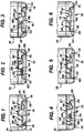
- FIGS. 1-6 show six embodiments of wave-type bases having the sidewall section 29, a contact ring 114 and an axially-inwardly extending pressure relief section 116 spaced radially-inwardly from the contact ring.
- the pressure relief section 116 is asymmetrical in cross sectional dimension and under static conditions so that one portion of the pressure relief section 116 yields under a first pressure and a second portion of the pressure relief section yields under a second pressure different from the first pressure (See FIGS. 9-12 ).
- the pressure relief section 116 has a first generally vertically extending wall 118, a first radially inwardly extending rounded transition 120, a second generally vertically extending wall 122, a second radially inwardly extending rounded transition 124, a first transition panel 126, a second transition panel 127 and a central push up 128.
- the first and second transition panels 126, 127 define a generally toroidal-shaped channel circumscribing the central pushup 128.
- the second rounded transition 124 has sections and spaced apart by 180°. The radius of curvature of the first portion is different from the radius of curvature at portion to define an assymetric pressure relief panel.
- FIGS. 1-6 show the 180° embodiment.
- the first transition 120 has opposed rounded sections 130, 132 and a straight section 134 therebetween.
- the first and second transition panels 126 and 127 have geometries that differ in at least one dimension to render the shape of the pressure relief section 116 asymmetrical.
- FIGS. 1, 3 have generally concave or semi-circular shaped transition panels 126 and 127 with the radius of curvature of the panels being different from one another. More particularly, in FIGS. 1 and 3 the second transition panel 127 has an axially deeper shape than the first transition panel 126, and, therefore, presents greater resistance to yielding under negative pressure within the container and less resistance to yielding under positive pressure within the container.
- the pressure relief panel is asymmetric under static conditions due to having differences in the slope of the panel from the second transition at various circumferentially spaced points along a top of the perimeter wall to define a slope angle gradient between a maximum and a minimum.
- FIGS. 2 and 6 the transition panels 126, 127 having a first leg 136 and a second leg 138.
- the first leg is generally downwardly sloping and radially inwardly extending along a straight line and the second leg is rounded.
- the downwardly sloping line forms an angle [alpha] with a horizontal line (radial) of from 5 degrees to 45 degrees and more preferably from 10 degrees to 30 degrees.
- Asymmetry results from differing [alpha] angles of the first leg of each of the first and second transition panels 126 and 127.
- the difference in the [alpha] angles between the first and second panels 126, 127 will from 3 degrees to 30 degrees and more preferably from 5 degrees to 20 degrees.
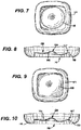
- FIGS. 7 and 8 show the pressure relief section 116 has a generally round shape and FIGS. 9 and 10 show the pressure relief section 116 has a generally square shape.
- the contact ring in FIGS. 7-10 is generally square shaped with rounded verticies. It should be understood, however, that it is contemplated both the pressure relief section and the contact ring could have other shapes such as circular, oval, polygonal and irregular without departing from the scope of the present invention.
- the push up 128 is generally a truncated cone having a generally vertically extending wall 142 tapering axially inwardly from a first point to a second point axially inwardly from the first and having a generally flat top wall 144.
- the top wall 144 of the push up 128 will extend axially inwardly beyond the second transition 126 by a distance 146 within the range of from 1,5875 cm (0.625 inches) to 2,8575 cm (1.125 inches).
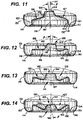
- FIGS. 11-14 show a representative wave base in various pressure conditions.
- FIG. 11 shows the first and second transition panels 126 and 127 fully inverted in response to a vacuum or negative pressure within the container.
- FIG. 12 shows the first transition panel 126 beginning to invert causing the upper surface of the pushup to form an angle [beta] with an axis 147.
- FIG. 13 shows the base when the pressure in the container is at atmospheric pressure.
- FIG. 14 shows the base flexed axially outwardly in response to a positive pressure within the container.
- a barrier layer or coating can be used provided the material has no adverse effects on the intended use of the container.
- One suitable coating material is a silicon oxygen coating (SiOx) deposited on a surface of the container, preferably on an interior surface, using techniques such as plasma deposition.
- SiOx silicon oxygen coating
- Other suitable barrier materials and coatings are well known to those skilled in the art.
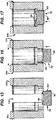
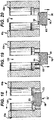
- FIGS. 15-20 show a blow station, which is not part of the present invention, with a blow mold having a two-piece pushup assembly 76' having a first section 98 and a second section 100 coaxially disposed about the first section 98.
- FIGS. 15-17 show three sequential steps in closing a mold and FIGS. 18-20 show three sequential steps in opening a mold.
- FIG. 15 shows a blow mold having first and second portions 101 a,b. separated from one another forming a gap 102.
- the first and second portions 101 a,b. are mounted for reciprocal translational movement from an open position to a closed position.
- a finished container (not shown) is removed from the mold and a new preform is inserted.
- the closed position the process of blow molding the container occurs.
- the first and second pushup sections 98 and 100 are also mounted for reciprocating translational motion from retracted positions to molding positions independent of one another.
- the pushup sections will move along a line that is transverse to the line upon which the first and second mold portions 101 a,b move and even more preferably in a line essentially perpendicular thereto.
- both the first and second pushup sections 98 and 100 are capable of being independently moved axially away from the mold and independently into the mold. That is, the first section 98 and the second section 100 are mounted for reciprocating translational motion between positions inside the mold cavity and outside the mold cavity independent of one another.
- the first and second sections 98 and 100 are capable of being independently moved axially into the mold cavity from a retracted position to a molding position.
- FIG. 15 shows the first and second sections 98 and 100 in a retracted position
- FIG. 16 shows second section 100 in a molding position with the first section 98 in the retracted position
- FIG. 17 shows both the first and second sections 98 and 100 in the molding position.
- the blow mold which is not part of the present invention, is for use in extrusion blow moulding, preferably for use in a three step method for closing ( FIGS.15-17 ) and opening ( FIGS. 18-20 ) the mold.
- FIG. 15 shows the two sections of the mold 101 a,b in a first open position and the two sections of the pushup 98 and 100 are in their retracted positions.
- FIG. 16 shows the two portions of the mold 101 a,b after moving in the direction of the arrows to a second closed position, the first section of the pushup 98 having moved axially inwardly into the molding position and the second pushup section 100 remains in its retracted position. In the second closed position, the standing ring 27 and upstanding wall 29are formed.
- FIG. 17 shows the two sections of the mold 101 a,b in third closed position having the two sections of the pushup 98 and 100 are in their molding positions. In the third closed position the flexible panel wall is formed and the finished container is formed.
- FIG. 18 shows the two portions of the mold 101 a, b have moved to an open position and the two sections of the pushup 98 and 100 are in their molding positions.
- the finished container is exposed to ambient conditions and begins to cool.
- FIG. 19 shows the next step, while the two mold sections are in an open position, the first section 98 of the pushup is moved to its retracted position while the second section 100 remains in its molding position and continues to provide support to the finished container.
- FIG. 20 shows the two mold sections in the open position and both of the two sections of the pushup 98 and 100 are in their retracted positions.
- the position of the blow station shown in FIG. 20 is the same position as shown in FIG. 15 . It is in this position when the finished container is removed from the mold and a new preform is inserted and the process is repeated.
Landscapes
- Engineering & Computer Science (AREA)
- Mechanical Engineering (AREA)
- Manufacturing & Machinery (AREA)
- Ceramic Engineering (AREA)
- Containers Having Bodies Formed In One Piece (AREA)
- Blow-Moulding Or Thermoforming Of Plastics Or The Like (AREA)
- Moulds For Moulding Plastics Or The Like (AREA)
- Pressure Vessels And Lids Thereof (AREA)
- Sampling And Sample Adjustment (AREA)
Description
- This invention relates to a plastic container comprising a pressure compensating base used in hot fill, pasteurization and retort applications..
- Blow molding processes for forming polymeric containers are well known in the art. Blown polymeric containers have replaced metal and glass containers in numerous food storage applications such as carbonated soft drinks and lower temperature filled food products such as peanut butter and mayonnaise. However, certain prior art containers such as polyethylene terephtalate ("PET") containers have not replaced metal and glass containers for product storage and processing applications where the container is filled or heated to temperatures above 97 °C. (207° F.) as such containers experience significant shrinkage, deformation rendering the container unuseable.
- Additional in-roads into the replacement of glass are desired in food processing applications such as low-temperature pasteurization, high-temperature pasteurization and retort. Low temperature pasteurization includes the pasteurization of liquid products such as beer and tea. High temperature pasteurization processes are for solid food products such as pickles that have slower heat transfer rates and require temperatures in excess of 100 °C. Retort processes are for pasteurizing low acid products and require temperatures from 100 °C. to 130 °C. and pressures sufficient to maintain water in a liquid state.
- In numerous food storage applications, polymeric containers are filled with a hot liquid or solid material, the container is capped and then allowed to cool. To compensate for the change in volume inside the container it is known to provide pressure compensating features in various locations on the container sidewall including the dome, the barrel and the bottom panel. The pressure compensating features move in response to pressure changes to decrease or increase the volume as needed.
US 2009/0202766 ;2009/0159556 ;US 7,451,886 ;7,150,372 ;6,942,116 ; and6,595,380 ; disclose a volume compensating feature on a bottom panel of the container having a centrally disposed generally inverted cone shaped push-up section that extends to an axially inwardly most point when compared to other portions of the bottom panel. The push up section is connected by a generally S-shaped panel to a standing ring. The S-shaped panel inverts to compensate for negative pressure in the container. In the '556 publication, the standing ring is connected to a toroidal part of the S-shaped panel by a wall portion which extends at an angle greater than 80° from a horizontal line. The '556 publication further discloses providing a plurality of axially spaced circumferentially extending grooves on the S-shaped panel that extend through the entire thickness of the wall and form ribs on an opposite side of the groove or a plurality of circumferentially and axially spaced dimples. The bottom panels are symmetrically disposed about an axis of the container. -
U.S. Pat. Nos. 6,983,858 ;6,857,531 and5,234,126 disclose a pressure compensating base for a polymeric container that under static pressure the bottom panel is convex, or extends axially outwardly, and snaps through to a concave configuration, or extends axially inwardly, when a specific pressure is reached within the container. - United States Patent Application Publication No.
2006/0231985 discloses a method and apparatus for manufacturing a blow molded container. A parison is mounted within a mold assembly having two side molds and a base mold. The parison is inflated in contact with surfaces of the mold assembly to form a container with a bottom wall having a moveable region. The moveable region is downwardly convex with respect to a bearing surface and has a centrally disposed dimple. After the inflation step is complete, a rod mounted within the base mold for reciprocating translational motion along an axis of the container is moved axially inwardly so that a rod end engages the dimple of the moveable region to reposition the moveable region axially inwardly to an interior portion of the container with respect to the bearing surface. - United States Patent Publication No.
2008/0047964 discloses a plastic container having an invertible base for pressure compensation. A pressure panel is deeply set into the container and is moveable between an outwardly-inclined position to an inwardly inclined position to reduce the internal volume of the container and to compensate for vacuum forces created during a hot-fill process. The pressure panel is connected to the standing ring by an inner wall that is parallel or nearly parallel to a longitudinal axis of the container. To facilitate movement of the pressure panel between the outwardly-inclined position to the inwardly-inclined position, the pressure panel can include a hinge structure that is located between the inner wall and the pressure panel. The pressure panel can have an initiator portion and a control portion where the control portion has a steeper angle with respect to a standing plane than the initiator portion. The '964 application further discloses a pressure panel divided into fluted regions to create regions of lesser and greater angular inclination. -
US 2009/159556 A1 discloses a plastic container having a base portion, a contact ring, an upstanding wall, a central portion, a pushup and an inversion ring. -
JPH 05 254 531 A -
JPH 06 270 235 A - The present invention will be discussed with reference to the following drawings and accompanying specification.
- The present invention provides a plastic container according to claim 1 having a sidewall defining a chamber and having a first end and a second end and an opening at the first end into the chamber. A base extends from the sidewall and closes the second end. The base has an outer perimeter portion defining a support structure and an axially inwardly extending perimeter wall spaced radially inwardly from the support structure forming an angle with a horizontal line of greater than 80°. A centrally disposed push-up section in the shape of an axially inwardly extending truncated cone and a toroidal-shaped channel circumscribing and connects the perimeter wall to the push-up. The toroidal-shaped channel has a surface that is asymmetrical about a central axis of the container when the container is under static pressure conditions. Preferred embodiments of the plastic container are defined in subclaims 2 to 6.
-
-
FIGS. 1-6 are side sectional views of a base of a container having a progressive-type or wave-type release rate; -
FIGS. 7 and 8 respectively are bottom view and a side sectional view of wave or progressive base with a generally circular pressure relief section within a generally square standing ring; -
FIGS. 9 and 10 respectively are a bottom view and a side sectional view of wave or progressive base with a generally square pressure relief section within a generally square standing ring; -
FIGS. 11-14 show side elevation views of a representative wave base on a container respectively under various pressure conditions including under vacuum with the base fully inverted, under vacuum with the base partially inverted, under static pressure conditions and under positive pressure. -
FIG. 15 is a side elevation view in cross-section of the blow station, which is not part of the present invention, having a blow mold in an open condition with a two-piece pushup member in a retracted position; -
FIG. 16 is a side elevation view in cross-section of the blow station, which is not part of the present invention, with the blow mold moving to a closed position and a first portion of the pushup in a molding position and a second portion in a retracted position; -
FIG. 17 is a side elevation view in cross-section of the blow station, which is not part of the present invention, with the blow mold in a closed position with the first portion and the second portion of the pushup in a molding position; -
FIG. 18 is a side elevation view of the blow mold, which is not part of the present invention, moving to an open position with the first and second portions of the pushup inserted into the mold cavity; -
FIG. 19 is a side elevation view of the blow mold, which is not part of the present invention, in an open position with the first portion of the pushup inserted into the mold cavity and the second portion in a retracted position; -
FIG. 20 is a side elevation view of the blow mold, which is not part of the present invention, moving to an open position with the first and second portions of the pushup in a retracted position. - While this invention is susceptible of embodiment in many different forms, there is shown in the drawings, and will be described herein in detail, specific embodiments thereof with the understanding that the present disclosure is to be considered as an exemplification of the principles of the invention and is not intended to limit the invention to the specific embodiments illustrated.
- The plastic container according to the present invention provides a pressure compensating base, preferably the containers are of a crystallizable polymer having enhanced thermal properties while still providing a container with high clarity. Suitable crystallizable polymers include, for example, homopolymers of poly (ethylene terephthalate) and phthalic based copolymers ("PET"), polyolefins, polypropylene and polyethylene. Suitable polyolefins include homopolymers and copolymers of olefins with comonomers of olefins, ethers, esters, amides and others well know to those skilled in the art. Suitable polyethylenes include homopolymers and copolymers of ethylene and also include high, medium and low density polyethylenes.
-
FIGS. 1-6 show six embodiments of wave-type bases having thesidewall section 29, acontact ring 114 and an axially-inwardly extendingpressure relief section 116 spaced radially-inwardly from the contact ring. Thepressure relief section 116 is asymmetrical in cross sectional dimension and under static conditions so that one portion of thepressure relief section 116 yields under a first pressure and a second portion of the pressure relief section yields under a second pressure different from the first pressure (SeeFIGS. 9-12 ). In one preferred form of the invention, thepressure relief section 116 has a first generally vertically extendingwall 118, a first radially inwardly extendingrounded transition 120, a second generally vertically extendingwall 122, a second radially inwardly extendingrounded transition 124, afirst transition panel 126, asecond transition panel 127 and a central push up 128. The first andsecond transition panels central pushup 128. The secondrounded transition 124 has sections and spaced apart by 180°. The radius of curvature of the first portion is different from the radius of curvature at portion to define an assymetric pressure relief panel. Thus, there will be a radii of curvature gradient between a maximum and a minimum. In one preferred form of the invention the maximum and minimum radii of curvature will be separated by 120° and in another form of the invention by 180°.FIGS. 1-6 show the 180° embodiment. In the embodiment where the maximum and minimums are separated by 120° there will be one 120° panel going from the minimum curvature to the maximum curvature, a second 120° segment going from the maximum curvature to the minimum curvature and finally a third 120° segment where there is no change in the radius of curvature. Thefirst transition 120 has opposed roundedsections straight section 134 therebetween. - Due to the radii of curvature gradients in the 180° embodiment, the first and
second transition panels pressure relief section 116 asymmetrical. In the 120° embodiment there would be three panels of differing shapes with a first panel having an upwardly sloping surface from the minimum to the maximum, a second panel with a downwardly sloping surface from the maximum to the minimum and a third panel that is essentially flat with a constant radius of curvature over the entire surface.FIGS. 1, 3 have generally concave or semi-circular shapedtransition panels FIGS. 1 and 3 thesecond transition panel 127 has an axially deeper shape than thefirst transition panel 126, and, therefore, presents greater resistance to yielding under negative pressure within the container and less resistance to yielding under positive pressure within the container. - In another preferred form of the invention, the pressure relief panel is asymmetric under static conditions due to having differences in the slope of the panel from the second transition at various circumferentially spaced points along a top of the perimeter wall to define a slope angle gradient between a maximum and a minimum.
FIGS. 2 and 6 , thetransition panels first leg 136 and asecond leg 138. The first leg is generally downwardly sloping and radially inwardly extending along a straight line and the second leg is rounded. The downwardly sloping line forms an angle [alpha] with a horizontal line (radial) of from 5 degrees to 45 degrees and more preferably from 10 degrees to 30 degrees. Asymmetry results from differing [alpha] angles of the first leg of each of the first andsecond transition panels - In a preferred form of the invention, the difference in the [alpha] angles between the first and
second panels -
FIGS. 7 and 8 show thepressure relief section 116 has a generally round shape andFIGS. 9 and 10 show thepressure relief section 116 has a generally square shape. The contact ring inFIGS. 7-10 is generally square shaped with rounded verticies. It should be understood, however, that it is contemplated both the pressure relief section and the contact ring could have other shapes such as circular, oval, polygonal and irregular without departing from the scope of the present invention. - In a preferred form of the present invention, the push up 128 is generally a truncated cone having a generally vertically extending
wall 142 tapering axially inwardly from a first point to a second point axially inwardly from the first and having a generally flattop wall 144. In a preferred form of the invention, thetop wall 144 of the push up 128 will extend axially inwardly beyond thesecond transition 126 by adistance 146 within the range of from 1,5875 cm (0.625 inches) to 2,8575 cm (1.125 inches). -
FIGS. 11-14 show a representative wave base in various pressure conditions.FIG. 11 shows the first andsecond transition panels FIG. 12 shows thefirst transition panel 126 beginning to invert causing the upper surface of the pushup to form an angle [beta] with anaxis 147.FIG. 13 shows the base when the pressure in the container is at atmospheric pressure.FIG. 14 shows the base flexed axially outwardly in response to a positive pressure within the container. - For containers in need of enhanced gas or water vapor transmission rates, a barrier layer or coating can be used provided the material has no adverse effects on the intended use of the container. One suitable coating material is a silicon oxygen coating (SiOx) deposited on a surface of the container, preferably on an interior surface, using techniques such as plasma deposition. Other suitable barrier materials and coatings are well known to those skilled in the art.
-
FIGS. 15-20 show a blow station, which is not part of the present invention, with a blow mold having a two-piece pushup assembly 76' having afirst section 98 and asecond section 100 coaxially disposed about thefirst section 98.FIGS. 15-17 show three sequential steps in closing a mold andFIGS. 18-20 show three sequential steps in opening a mold. -
FIG. 15 shows a blow mold having first and second portions 101 a,b. separated from one another forming agap 102. The first and second portions 101 a,b. are mounted for reciprocal translational movement from an open position to a closed position. When in the open position shown inFIG. 15 , a finished container (not shown) is removed from the mold and a new preform is inserted. When in the closed position, the process of blow molding the container occurs. - The first and
second pushup sections second pushup sections first section 98 and thesecond section 100 are mounted for reciprocating translational motion between positions inside the mold cavity and outside the mold cavity independent of one another. In a preferred form of the invention, the first andsecond sections FIG. 15 shows the first andsecond sections FIG. 16 showssecond section 100 in a molding position with thefirst section 98 in the retracted position andFIG. 17 shows both the first andsecond sections - The blow mold, which is not part of the present invention, is for use in extrusion blow moulding, preferably for use in a three step method for closing (
FIGS.15-17 ) and opening (FIGS. 18-20 ) the mold.FIG. 15 shows the two sections of the mold 101 a,b in a first open position and the two sections of thepushup FIG. 16 shows the two portions of the mold 101 a,b after moving in the direction of the arrows to a second closed position, the first section of thepushup 98 having moved axially inwardly into the molding position and thesecond pushup section 100 remains in its retracted position. In the second closed position, the standing ring 27 and upstanding wall 29are formed.FIG. 17 shows the two sections of the mold 101 a,b in third closed position having the two sections of thepushup -
FIG. 18 shows the two portions of the mold 101 a, b have moved to an open position and the two sections of thepushup FIG. 19 shows the next step, while the two mold sections are in an open position, thefirst section 98 of the pushup is moved to its retracted position while thesecond section 100 remains in its molding position and continues to provide support to the finished container.FIG. 20 shows the two mold sections in the open position and both of the two sections of thepushup FIG. 20 is the same position as shown inFIG. 15 . It is in this position when the finished container is removed from the mold and a new preform is inserted and the process is repeated.
Claims (6)
- A plastic container comprising:• a sidewall (29) defining a chamber and having a first end and a second end and an opening at the first end into the chamber; and• a base extending from the sidewall (29) and closing the second end, the base having:∘ an outer perimeter portion defining a support structure (114),∘ an axially inwardly extending perimeter wall (122) spaced radially inwardly from the support structure (114) forming an angle with a horizontal line of greater than 80°,∘ a centrally disposed push-up section (116) in the shape of an axially inwardly extending truncated cone (128) and∘ a toroidal-shaped channel (126, 127) circumscribing said push-up and connecting the perimeter wall (122) to the push-up, characterised in that the toroidal-shaped channel has a surface that is asymmetrical about a central axis of the container when the container is under positive pressure conditions.
- The container of claim 1 wherein the surface of the toroidal-shaped channel (126, 127) has a rounded transition (120, 124) having a first radius of curvature at a first point and a second radius of curvature at a second point circumferentially spaced from the first point, the first radius of curvature being different from the second radius of curvature.
- The container of claim 2 wherein the first point is spaced from the second point at an angle from 120° to 180°.
- The container of claim 1, wherein:• the surface of the toroidal-shaped channel (126, 127) has a first portion and a second portion circumferentially spaced from the first portion,∘ the first portion forming a first angle with a horizontal line and the second portion forming a second angle with a horizontal line, and∘ the first angle is different from the second angle.
- The container of claim 4 wherein the difference between the first angle and the second angle is less than 30 degrees.
- The container of claim 1 wherein the axially inwardly extending perimeter wall (122) spaced radially inwardly from the support structure (114) forms an angle with a horizontal line of from 80° to 90°.
Priority Applications (2)
| Application Number | Priority Date | Filing Date | Title |
|---|---|---|---|
| PL15197230T PL3025985T3 (en) | 2010-02-19 | 2011-02-17 | Pressure-compensating bases for polymer containers |
| EP16202411.1A EP3175970A1 (en) | 2010-02-19 | 2011-02-17 | Blowmould and method |
Applications Claiming Priority (3)
| Application Number | Priority Date | Filing Date | Title |
|---|---|---|---|
| US12/709,302 US8444002B2 (en) | 2010-02-19 | 2010-02-19 | Pressure compensating bases for polymeric containers |
| EP11706411.3A EP2536644B1 (en) | 2010-02-19 | 2011-02-17 | Pressure compensating bases for polymeric containers |
| PCT/US2011/025254 WO2011103296A2 (en) | 2010-02-19 | 2011-02-17 | Pressure compensating bases for polymeric containers |
Related Parent Applications (1)
| Application Number | Title | Priority Date | Filing Date |
|---|---|---|---|
| EP11706411.3A Division EP2536644B1 (en) | 2010-02-19 | 2011-02-17 | Pressure compensating bases for polymeric containers |
Related Child Applications (2)
| Application Number | Title | Priority Date | Filing Date |
|---|---|---|---|
| EP16202411.1A Division-Into EP3175970A1 (en) | 2010-02-19 | 2011-02-17 | Blowmould and method |
| EP16202411.1A Division EP3175970A1 (en) | 2010-02-19 | 2011-02-17 | Blowmould and method |
Publications (2)
| Publication Number | Publication Date |
|---|---|
| EP3025985A1 EP3025985A1 (en) | 2016-06-01 |
| EP3025985B1 true EP3025985B1 (en) | 2019-04-17 |
Family
ID=43983285
Family Applications (3)
| Application Number | Title | Priority Date | Filing Date |
|---|---|---|---|
| EP15197230.4A Active EP3025985B1 (en) | 2010-02-19 | 2011-02-17 | Pressure compensating bases for polymeric containers |
| EP11706411.3A Active EP2536644B1 (en) | 2010-02-19 | 2011-02-17 | Pressure compensating bases for polymeric containers |
| EP16202411.1A Withdrawn EP3175970A1 (en) | 2010-02-19 | 2011-02-17 | Blowmould and method |
Family Applications After (2)
| Application Number | Title | Priority Date | Filing Date |
|---|---|---|---|
| EP11706411.3A Active EP2536644B1 (en) | 2010-02-19 | 2011-02-17 | Pressure compensating bases for polymeric containers |
| EP16202411.1A Withdrawn EP3175970A1 (en) | 2010-02-19 | 2011-02-17 | Blowmould and method |
Country Status (9)
| Country | Link |
|---|---|
| US (3) | US8444002B2 (en) |
| EP (3) | EP3025985B1 (en) |
| JP (3) | JP5735012B2 (en) |
| AU (1) | AU2011218086A1 (en) |
| CA (3) | CA2789210C (en) |
| ES (2) | ES2564325T3 (en) |
| MX (3) | MX2012009509A (en) |
| PL (2) | PL3025985T3 (en) |
| WO (1) | WO2011103296A2 (en) |
Families Citing this family (31)
| Publication number | Priority date | Publication date | Assignee | Title |
|---|---|---|---|---|
| US20130213980A1 (en) * | 2008-12-31 | 2013-08-22 | Plastipak Packaging, Inc. | Plastic container with flexible base |
| US9023446B2 (en) | 2009-09-22 | 2015-05-05 | Graham Packaging Lc, L.P. | PET containers with enhanced thermal properties and process for making same |
| US8507063B2 (en) * | 2009-09-22 | 2013-08-13 | Graham Packaging Lc, L.P. | Pet containers with enhanced thermal properties |
| AT510506B1 (en) * | 2010-09-22 | 2013-01-15 | Red Bull Gmbh | FLOOR CONSTRUCTION FOR A PLASTIC BOTTLE |
| US8991628B2 (en) * | 2010-11-12 | 2015-03-31 | Graham Packaging Company, L.P. | Hot-fill jar base |
| MX363487B (en) | 2011-11-15 | 2019-03-25 | Amcor Rigid Plastics Usa Llc | USE OF MULTIPLE STRAIGHT AGAINST BALANCED BAR AND / OR ASCENDING DISPLACEMENT BASE. |
| JP2013144560A (en) * | 2012-01-16 | 2013-07-25 | Toyo Seikan Group Holdings Ltd | Synthetic resin made container |
| CN104321270B (en) * | 2012-03-30 | 2016-03-02 | 帝斯克玛股份有限公司 | For the manufacture of the method for container, method, filling containers, blow molding method and the blow molding apparatus for the internal pressurization to container that filling fluid is housed |
| CA2871915A1 (en) * | 2012-05-01 | 2013-11-07 | Berry Plastics Corporation | Retortable package |
| US9145251B2 (en) | 2012-10-26 | 2015-09-29 | Berry Plastics Corporation | Package |
| EP2764967B1 (en) * | 2013-02-06 | 2015-10-14 | Sidel Participations | Mold for blow molding a hot-fill container with increased stretch ratios |
| USD708953S1 (en) | 2013-03-15 | 2014-07-15 | The Folger Coffee Company | Container |
| US9038848B2 (en) | 2013-07-23 | 2015-05-26 | Graham Packaging Company, L.P. | Base for hot-fill plastic containers |
| US10710765B2 (en) | 2013-07-23 | 2020-07-14 | Graham Packaging Company, L.P. | Base for hot-fill plastic containers |
| FR3019486B1 (en) | 2014-04-02 | 2016-12-23 | Sidel Participations | MANUFACTURING METHOD AND MOLDING UNIT OF CONTAINERS WITH LARGE BOXING RUN |
| EP2957522B1 (en) * | 2014-06-17 | 2017-05-03 | Sidel Participations | Container provided with a curved invertible diaphragm |
| CA2898810C (en) * | 2014-08-01 | 2017-01-03 | Nicolas Bouveret | Anti-depression plastic container |
| MX382105B (en) * | 2014-08-21 | 2025-03-13 | Amcor Rigid Plastics Usa Llc | CONTAINER WITH FOLDED SIDE WALL. |
| CA2958343C (en) | 2014-08-21 | 2022-04-19 | Amcor Limited | Container base including hemispherical actuating diaphragm |
| US9725802B2 (en) | 2014-11-11 | 2017-08-08 | Graham Packaging Company, L.P. | Method for making pet containers with enhanced silicon dioxide barrier coating |
| JP6465664B2 (en) * | 2015-01-22 | 2019-02-06 | 三笠産業株式会社 | container |
| JP2017001705A (en) * | 2015-06-10 | 2017-01-05 | 東洋製罐株式会社 | Synthetic resin container |
| EP3109176A1 (en) | 2015-06-23 | 2016-12-28 | Sidel Participations | Container provided with a curved invertible diaphragm |
| CH711621A1 (en) | 2015-10-08 | 2017-04-13 | Alpla Werke Alwin Lehner Gmbh & Co Kg | Preform for producing a plastic container in a stretch blow molding process. |
| US20180194058A1 (en) * | 2017-01-06 | 2018-07-12 | Friendship Products Llc | Molding systems and related methods |
| USD828729S1 (en) * | 2017-03-16 | 2018-09-18 | Progressive International Corporation | Herb keeper with lifting insert |
| AU2018254774A1 (en) * | 2017-04-21 | 2019-12-12 | Can Forming Technologies, Llc | Dome formation profile and method of lightweight container design and manufacture |
| CH715202A1 (en) * | 2018-07-25 | 2020-01-31 | Alpla Werke Alwin Lehner Gmbh & Co Kg | Stretch blow molding process for the production of a plastic container and plastic container produced in a stretch blow molding process. |
| JP7756482B2 (en) | 2019-03-22 | 2025-10-20 | メビウスパッケージング株式会社 | Synthetic resin containers |
| WO2021060196A1 (en) * | 2019-09-25 | 2021-04-01 | 日精エー・エス・ビー機械株式会社 | Blow molding device and blow molding method |
| CH719070A9 (en) * | 2021-10-18 | 2023-06-30 | Alpla Werke Alwin Lehner Gmbh & Co Kg | reusable plastic container. |
Citations (1)
| Publication number | Priority date | Publication date | Assignee | Title |
|---|---|---|---|---|
| JPH06270235A (en) * | 1993-03-19 | 1994-09-27 | Nissei Asb Mach Co Ltd | Molding of container |
Family Cites Families (36)
| Publication number | Priority date | Publication date | Assignee | Title |
|---|---|---|---|---|
| JPS5470184A (en) * | 1977-11-14 | 1979-06-05 | Yoshino Kogyosho Co Ltd | Bottle made of polyethylene terephthalate and method of forming said bottle |
| US4465199A (en) | 1981-06-22 | 1984-08-14 | Katashi Aoki | Pressure resisting plastic bottle |
| JPS58183308U (en) * | 1982-05-31 | 1983-12-06 | 青木 固 | Bottom structure of pressure-resistant synthetic resin container |
| US4667454A (en) * | 1982-01-05 | 1987-05-26 | American Can Company | Method of obtaining acceptable configuration of a plastic container after thermal food sterilization process |
| US4880129A (en) * | 1983-01-05 | 1989-11-14 | American National Can Company | Method of obtaining acceptable configuration of a plastic container after thermal food sterilization process |
| DE3344779A1 (en) * | 1983-12-10 | 1985-06-20 | Gizeh-Werk Gmbh, 5275 Bergneustadt | MUG-shaped container |
| JPH0423766Y2 (en) * | 1986-02-21 | 1992-06-03 | ||
| US5234126A (en) | 1991-01-04 | 1993-08-10 | Abbott Laboratories | Plastic container |
| JPH05254531A (en) | 1992-03-13 | 1993-10-05 | Dainippon Printing Co Ltd | Pressure resisting self-standing container, method for production thereof and blow molding die thereof |
| GB9216247D0 (en) * | 1992-07-30 | 1992-09-09 | Cmb Foodcan Plc | Souffle:can ends |
| FR2714631B1 (en) * | 1993-12-30 | 1996-03-01 | Sidel Sa | Method and installation for the manufacture of containers, in particular bottles, of thermoplastic material. |
| EP0778224A1 (en) * | 1995-12-05 | 1997-06-11 | Alusuisse Technology & Management AG | Gastight container |
| FR2765515B1 (en) * | 1997-07-04 | 1999-09-24 | Grosfillex Sarl | DEVICE AND METHOD FOR MANUFACTURING AN OBJECT IN PLASTIC MATERIAL BY BLOWING |
| JP4336425B2 (en) | 1999-09-22 | 2009-09-30 | 北海製罐株式会社 | Blow molding method |
| DE10030010C2 (en) * | 2000-06-17 | 2002-05-02 | Illig Maschinenbau Adolf | Process for producing a container from a thermoplastic film and mold for carrying out the process |
| US6595380B2 (en) * | 2000-07-24 | 2003-07-22 | Schmalbach-Lubeca Ag | Container base structure responsive to vacuum related forces |
| NZ521694A (en) * | 2002-09-30 | 2005-05-27 | Co2 Pac Ltd | Container structure for removal of vacuum pressure |
| US8584879B2 (en) | 2000-08-31 | 2013-11-19 | Co2Pac Limited | Plastic container having a deep-set invertible base and related methods |
| US6983858B2 (en) | 2003-01-30 | 2006-01-10 | Plastipak Packaging, Inc. | Hot fillable container with flexible base portion |
| US6857531B2 (en) | 2003-01-30 | 2005-02-22 | Plastipak Packaging, Inc. | Plastic container |
| US6942116B2 (en) | 2003-05-23 | 2005-09-13 | Amcor Limited | Container base structure responsive to vacuum related forces |
| US7150372B2 (en) | 2003-05-23 | 2006-12-19 | Amcor Limited | Container base structure responsive to vacuum related forces |
| US8276774B2 (en) | 2003-05-23 | 2012-10-02 | Amcor Limited | Container base structure responsive to vacuum related forces |
| US7451886B2 (en) | 2003-05-23 | 2008-11-18 | Amcor Limited | Container base structure responsive to vacuum related forces |
| FR2856380B1 (en) * | 2003-06-19 | 2005-10-21 | Sidel Sa | CONTAINER IN THERMOPLASTIC MATERIAL AND CHAMPAGNE BASE |
| US20050170035A1 (en) * | 2004-02-02 | 2005-08-04 | Shou-Te Chen | Container and container fabrication dies |
| JP4553641B2 (en) * | 2004-06-28 | 2010-09-29 | 大日本印刷株式会社 | Plastic container |
| US8075833B2 (en) | 2005-04-15 | 2011-12-13 | Graham Packaging Company L.P. | Method and apparatus for manufacturing blow molded containers |
| PL1976679T3 (en) | 2006-01-11 | 2012-10-31 | Graham Packaging Co | Method and apparatus for forming stretch blow molded containers |
| US7799264B2 (en) * | 2006-03-15 | 2010-09-21 | Graham Packaging Company, L.P. | Container and method for blowmolding a base in a partial vacuum pressure reduction setup |
| JP4953674B2 (en) * | 2006-03-23 | 2012-06-13 | 北海製罐株式会社 | Plastic bottle |
| JP2007290772A (en) * | 2006-04-27 | 2007-11-08 | Hokkai Can Co Ltd | Synthetic resin bottle and method for producing synthetic resin bottle |
| JP5239070B2 (en) * | 2007-10-25 | 2013-07-17 | 北海製罐株式会社 | Recessed bottom of plastic bottle |
| US8313686B2 (en) | 2008-02-07 | 2012-11-20 | Amcor Limited | Flex ring base |
| US8507063B2 (en) | 2009-09-22 | 2013-08-13 | Graham Packaging Lc, L.P. | Pet containers with enhanced thermal properties |
| JP6270235B1 (en) | 2017-09-29 | 2018-01-31 | 株式会社すなおネット | Tableware products |
-
2010
- 2010-02-19 US US12/709,302 patent/US8444002B2/en active Active
-
2011
- 2011-02-17 ES ES11706411.3T patent/ES2564325T3/en active Active
- 2011-02-17 MX MX2012009509A patent/MX2012009509A/en active IP Right Grant
- 2011-02-17 CA CA2789210A patent/CA2789210C/en active Active
- 2011-02-17 PL PL15197230T patent/PL3025985T3/en unknown
- 2011-02-17 AU AU2011218086A patent/AU2011218086A1/en not_active Abandoned
- 2011-02-17 PL PL11706411T patent/PL2536644T3/en unknown
- 2011-02-17 CA CA3070189A patent/CA3070189C/en active Active
- 2011-02-17 JP JP2012554024A patent/JP5735012B2/en active Active
- 2011-02-17 CA CA2975925A patent/CA2975925C/en active Active
- 2011-02-17 EP EP15197230.4A patent/EP3025985B1/en active Active
- 2011-02-17 MX MX2014012182A patent/MX346163B/en unknown
- 2011-02-17 EP EP11706411.3A patent/EP2536644B1/en active Active
- 2011-02-17 WO PCT/US2011/025254 patent/WO2011103296A2/en not_active Ceased
- 2011-02-17 MX MX2016015387A patent/MX377040B/en unknown
- 2011-02-17 ES ES15197230T patent/ES2728094T3/en active Active
- 2011-02-17 EP EP16202411.1A patent/EP3175970A1/en not_active Withdrawn
-
2013
- 2013-05-17 US US13/896,683 patent/US9481485B2/en active Active
-
2015
- 2015-04-15 JP JP2015083492A patent/JP6055866B2/en not_active Expired - Fee Related
-
2016
- 2016-09-02 JP JP2016171674A patent/JP6279681B2/en not_active Expired - Fee Related
- 2016-10-04 US US15/284,622 patent/US10279530B2/en active Active
Patent Citations (1)
| Publication number | Priority date | Publication date | Assignee | Title |
|---|---|---|---|---|
| JPH06270235A (en) * | 1993-03-19 | 1994-09-27 | Nissei Asb Mach Co Ltd | Molding of container |
Also Published As
| Publication number | Publication date |
|---|---|
| PL2536644T3 (en) | 2016-05-31 |
| JP5735012B2 (en) | 2015-06-17 |
| EP2536644B1 (en) | 2015-12-02 |
| ES2564325T3 (en) | 2016-03-21 |
| US8444002B2 (en) | 2013-05-21 |
| PL3025985T3 (en) | 2019-09-30 |
| WO2011103296A2 (en) | 2011-08-25 |
| CA2975925A1 (en) | 2011-08-25 |
| US20110204067A1 (en) | 2011-08-25 |
| WO2011103296A3 (en) | 2012-01-05 |
| ES2728094T3 (en) | 2019-10-22 |
| US9481485B2 (en) | 2016-11-01 |
| MX2012009509A (en) | 2012-11-30 |
| JP2016204056A (en) | 2016-12-08 |
| EP3175970A1 (en) | 2017-06-07 |
| JP2015129023A (en) | 2015-07-16 |
| JP6055866B2 (en) | 2016-12-27 |
| CA2789210C (en) | 2017-09-26 |
| CA3070189A1 (en) | 2011-08-25 |
| US20130248539A1 (en) | 2013-09-26 |
| MX377040B (en) | 2025-03-04 |
| EP2536644A2 (en) | 2012-12-26 |
| US10279530B2 (en) | 2019-05-07 |
| CA3070189C (en) | 2021-08-31 |
| AU2011218086A1 (en) | 2012-09-06 |
| JP2013520371A (en) | 2013-06-06 |
| EP3025985A1 (en) | 2016-06-01 |
| MX346163B (en) | 2017-03-08 |
| US20170021549A1 (en) | 2017-01-26 |
| CA2975925C (en) | 2020-03-24 |
| CA2789210A1 (en) | 2011-08-25 |
| JP6279681B2 (en) | 2018-02-14 |
Similar Documents
| Publication | Publication Date | Title |
|---|---|---|
| EP3025985B1 (en) | Pressure compensating bases for polymeric containers | |
| KR890000229B1 (en) | Pressure resisting plastic bottle and forming process thereof | |
| JP5732458B2 (en) | High temperature filling container | |
| EP3137279B1 (en) | Blow moulded container and manufacture thereof | |
| MX2010012307A (en) | HOT FILLING CONTAINER. | |
| GB2153741A (en) | Apparatus for producing a container from a preform | |
| JPH0558382B2 (en) | ||
| JP2017521278A (en) | A heat-resistant biaxially stretched blow molded plastic container resulting from the double blow process with a movable base to accommodate internal vacuum forces | |
| JP2016534950A (en) | High temperature filling container | |
| WO2008059256A2 (en) | Method and apparatus for making a container with a pressure accomodating base |
Legal Events
| Date | Code | Title | Description |
|---|---|---|---|
| PUAI | Public reference made under article 153(3) epc to a published international application that has entered the european phase |
Free format text: ORIGINAL CODE: 0009012 |
|
| AC | Divisional application: reference to earlier application |
Ref document number: 2536644 Country of ref document: EP Kind code of ref document: P |
|
| AK | Designated contracting states |
Kind code of ref document: A1 Designated state(s): AL AT BE BG CH CY CZ DE DK EE ES FI FR GB GR HR HU IE IS IT LI LT LU LV MC MK MT NL NO PL PT RO RS SE SI SK SM TR |
|
| STAA | Information on the status of an ep patent application or granted ep patent |
Free format text: STATUS: REQUEST FOR EXAMINATION WAS MADE |
|
| 17P | Request for examination filed |
Effective date: 20161130 |
|
| RBV | Designated contracting states (corrected) |
Designated state(s): AL AT BE BG CH CY CZ DE DK EE ES FI FR GB GR HR HU IE IS IT LI LT LU LV MC MK MT NL NO PL PT RO RS SE SI SK SM TR |
|
| STAA | Information on the status of an ep patent application or granted ep patent |
Free format text: STATUS: EXAMINATION IS IN PROGRESS |
|
| 17Q | First examination report despatched |
Effective date: 20170324 |
|
| RAP1 | Party data changed (applicant data changed or rights of an application transferred) |
Owner name: GRAHAM PACKAGING PET TECHNOLOGIES INC. |
|
| GRAP | Despatch of communication of intention to grant a patent |
Free format text: ORIGINAL CODE: EPIDOSNIGR1 |
|
| STAA | Information on the status of an ep patent application or granted ep patent |
Free format text: STATUS: GRANT OF PATENT IS INTENDED |
|
| INTG | Intention to grant announced |
Effective date: 20190114 |
|
| GRAS | Grant fee paid |
Free format text: ORIGINAL CODE: EPIDOSNIGR3 |
|
| GRAA | (expected) grant |
Free format text: ORIGINAL CODE: 0009210 |
|
| STAA | Information on the status of an ep patent application or granted ep patent |
Free format text: STATUS: THE PATENT HAS BEEN GRANTED |
|
| AC | Divisional application: reference to earlier application |
Ref document number: 2536644 Country of ref document: EP Kind code of ref document: P |
|
| AK | Designated contracting states |
Kind code of ref document: B1 Designated state(s): AL AT BE BG CH CY CZ DE DK EE ES FI FR GB GR HR HU IE IS IT LI LT LU LV MC MK MT NL NO PL PT RO RS SE SI SK SM TR |
|
| REG | Reference to a national code |
Ref country code: GB Ref legal event code: FG4D |
|
| REG | Reference to a national code |
Ref country code: CH Ref legal event code: EP |
|
| REG | Reference to a national code |
Ref country code: DE Ref legal event code: R096 Ref document number: 602011058242 Country of ref document: DE |
|
| REG | Reference to a national code |
Ref country code: AT Ref legal event code: REF Ref document number: 1121301 Country of ref document: AT Kind code of ref document: T Effective date: 20190515 Ref country code: IE Ref legal event code: FG4D |
|
| REG | Reference to a national code |
Ref country code: NL Ref legal event code: FP |
|
| REG | Reference to a national code |
Ref country code: LT Ref legal event code: MG4D |
|
| REG | Reference to a national code |
Ref country code: ES Ref legal event code: FG2A Ref document number: 2728094 Country of ref document: ES Kind code of ref document: T3 Effective date: 20191022 |
|
| PG25 | Lapsed in a contracting state [announced via postgrant information from national office to epo] |
Ref country code: AL Free format text: LAPSE BECAUSE OF FAILURE TO SUBMIT A TRANSLATION OF THE DESCRIPTION OR TO PAY THE FEE WITHIN THE PRESCRIBED TIME-LIMIT Effective date: 20190417 Ref country code: NO Free format text: LAPSE BECAUSE OF FAILURE TO SUBMIT A TRANSLATION OF THE DESCRIPTION OR TO PAY THE FEE WITHIN THE PRESCRIBED TIME-LIMIT Effective date: 20190717 Ref country code: FI Free format text: LAPSE BECAUSE OF FAILURE TO SUBMIT A TRANSLATION OF THE DESCRIPTION OR TO PAY THE FEE WITHIN THE PRESCRIBED TIME-LIMIT Effective date: 20190417 Ref country code: SE Free format text: LAPSE BECAUSE OF FAILURE TO SUBMIT A TRANSLATION OF THE DESCRIPTION OR TO PAY THE FEE WITHIN THE PRESCRIBED TIME-LIMIT Effective date: 20190417 Ref country code: PT Free format text: LAPSE BECAUSE OF FAILURE TO SUBMIT A TRANSLATION OF THE DESCRIPTION OR TO PAY THE FEE WITHIN THE PRESCRIBED TIME-LIMIT Effective date: 20190817 Ref country code: HR Free format text: LAPSE BECAUSE OF FAILURE TO SUBMIT A TRANSLATION OF THE DESCRIPTION OR TO PAY THE FEE WITHIN THE PRESCRIBED TIME-LIMIT Effective date: 20190417 Ref country code: LT Free format text: LAPSE BECAUSE OF FAILURE TO SUBMIT A TRANSLATION OF THE DESCRIPTION OR TO PAY THE FEE WITHIN THE PRESCRIBED TIME-LIMIT Effective date: 20190417 |
|
| PG25 | Lapsed in a contracting state [announced via postgrant information from national office to epo] |
Ref country code: LV Free format text: LAPSE BECAUSE OF FAILURE TO SUBMIT A TRANSLATION OF THE DESCRIPTION OR TO PAY THE FEE WITHIN THE PRESCRIBED TIME-LIMIT Effective date: 20190417 Ref country code: RS Free format text: LAPSE BECAUSE OF FAILURE TO SUBMIT A TRANSLATION OF THE DESCRIPTION OR TO PAY THE FEE WITHIN THE PRESCRIBED TIME-LIMIT Effective date: 20190417 Ref country code: GR Free format text: LAPSE BECAUSE OF FAILURE TO SUBMIT A TRANSLATION OF THE DESCRIPTION OR TO PAY THE FEE WITHIN THE PRESCRIBED TIME-LIMIT Effective date: 20190718 Ref country code: BG Free format text: LAPSE BECAUSE OF FAILURE TO SUBMIT A TRANSLATION OF THE DESCRIPTION OR TO PAY THE FEE WITHIN THE PRESCRIBED TIME-LIMIT Effective date: 20190717 |
|
| REG | Reference to a national code |
Ref country code: AT Ref legal event code: MK05 Ref document number: 1121301 Country of ref document: AT Kind code of ref document: T Effective date: 20190417 |
|
| PG25 | Lapsed in a contracting state [announced via postgrant information from national office to epo] |
Ref country code: IS Free format text: LAPSE BECAUSE OF FAILURE TO SUBMIT A TRANSLATION OF THE DESCRIPTION OR TO PAY THE FEE WITHIN THE PRESCRIBED TIME-LIMIT Effective date: 20190817 |
|
| REG | Reference to a national code |
Ref country code: DE Ref legal event code: R097 Ref document number: 602011058242 Country of ref document: DE |
|
| PG25 | Lapsed in a contracting state [announced via postgrant information from national office to epo] |
Ref country code: CZ Free format text: LAPSE BECAUSE OF FAILURE TO SUBMIT A TRANSLATION OF THE DESCRIPTION OR TO PAY THE FEE WITHIN THE PRESCRIBED TIME-LIMIT Effective date: 20190417 Ref country code: RO Free format text: LAPSE BECAUSE OF FAILURE TO SUBMIT A TRANSLATION OF THE DESCRIPTION OR TO PAY THE FEE WITHIN THE PRESCRIBED TIME-LIMIT Effective date: 20190417 Ref country code: SK Free format text: LAPSE BECAUSE OF FAILURE TO SUBMIT A TRANSLATION OF THE DESCRIPTION OR TO PAY THE FEE WITHIN THE PRESCRIBED TIME-LIMIT Effective date: 20190417 Ref country code: DK Free format text: LAPSE BECAUSE OF FAILURE TO SUBMIT A TRANSLATION OF THE DESCRIPTION OR TO PAY THE FEE WITHIN THE PRESCRIBED TIME-LIMIT Effective date: 20190417 Ref country code: EE Free format text: LAPSE BECAUSE OF FAILURE TO SUBMIT A TRANSLATION OF THE DESCRIPTION OR TO PAY THE FEE WITHIN THE PRESCRIBED TIME-LIMIT Effective date: 20190417 Ref country code: AT Free format text: LAPSE BECAUSE OF FAILURE TO SUBMIT A TRANSLATION OF THE DESCRIPTION OR TO PAY THE FEE WITHIN THE PRESCRIBED TIME-LIMIT Effective date: 20190417 |
|
| PLBE | No opposition filed within time limit |
Free format text: ORIGINAL CODE: 0009261 |
|
| STAA | Information on the status of an ep patent application or granted ep patent |
Free format text: STATUS: NO OPPOSITION FILED WITHIN TIME LIMIT |
|
| PG25 | Lapsed in a contracting state [announced via postgrant information from national office to epo] |
Ref country code: SM Free format text: LAPSE BECAUSE OF FAILURE TO SUBMIT A TRANSLATION OF THE DESCRIPTION OR TO PAY THE FEE WITHIN THE PRESCRIBED TIME-LIMIT Effective date: 20190417 |
|
| 26N | No opposition filed |
Effective date: 20200120 |
|
| PG25 | Lapsed in a contracting state [announced via postgrant information from national office to epo] |
Ref country code: TR Free format text: LAPSE BECAUSE OF FAILURE TO SUBMIT A TRANSLATION OF THE DESCRIPTION OR TO PAY THE FEE WITHIN THE PRESCRIBED TIME-LIMIT Effective date: 20190417 |
|
| PG25 | Lapsed in a contracting state [announced via postgrant information from national office to epo] |
Ref country code: SI Free format text: LAPSE BECAUSE OF FAILURE TO SUBMIT A TRANSLATION OF THE DESCRIPTION OR TO PAY THE FEE WITHIN THE PRESCRIBED TIME-LIMIT Effective date: 20190417 |
|
| REG | Reference to a national code |
Ref country code: CH Ref legal event code: PL |
|
| PG25 | Lapsed in a contracting state [announced via postgrant information from national office to epo] |
Ref country code: LU Free format text: LAPSE BECAUSE OF NON-PAYMENT OF DUE FEES Effective date: 20200217 Ref country code: MC Free format text: LAPSE BECAUSE OF FAILURE TO SUBMIT A TRANSLATION OF THE DESCRIPTION OR TO PAY THE FEE WITHIN THE PRESCRIBED TIME-LIMIT Effective date: 20190417 |
|
| PG25 | Lapsed in a contracting state [announced via postgrant information from national office to epo] |
Ref country code: LI Free format text: LAPSE BECAUSE OF NON-PAYMENT OF DUE FEES Effective date: 20200229 Ref country code: CH Free format text: LAPSE BECAUSE OF NON-PAYMENT OF DUE FEES Effective date: 20200229 |
|
| PG25 | Lapsed in a contracting state [announced via postgrant information from national office to epo] |
Ref country code: IE Free format text: LAPSE BECAUSE OF NON-PAYMENT OF DUE FEES Effective date: 20200217 |
|
| PGFP | Annual fee paid to national office [announced via postgrant information from national office to epo] |
Ref country code: NL Payment date: 20210223 Year of fee payment: 11 |
|
| PGFP | Annual fee paid to national office [announced via postgrant information from national office to epo] |
Ref country code: BE Payment date: 20210224 Year of fee payment: 11 |
|
| PG25 | Lapsed in a contracting state [announced via postgrant information from national office to epo] |
Ref country code: MT Free format text: LAPSE BECAUSE OF FAILURE TO SUBMIT A TRANSLATION OF THE DESCRIPTION OR TO PAY THE FEE WITHIN THE PRESCRIBED TIME-LIMIT Effective date: 20190417 Ref country code: CY Free format text: LAPSE BECAUSE OF FAILURE TO SUBMIT A TRANSLATION OF THE DESCRIPTION OR TO PAY THE FEE WITHIN THE PRESCRIBED TIME-LIMIT Effective date: 20190417 |
|
| PGFP | Annual fee paid to national office [announced via postgrant information from national office to epo] |
Ref country code: PL Payment date: 20220217 Year of fee payment: 12 |
|
| PG25 | Lapsed in a contracting state [announced via postgrant information from national office to epo] |
Ref country code: MK Free format text: LAPSE BECAUSE OF FAILURE TO SUBMIT A TRANSLATION OF THE DESCRIPTION OR TO PAY THE FEE WITHIN THE PRESCRIBED TIME-LIMIT Effective date: 20190417 |
|
| REG | Reference to a national code |
Ref country code: NL Ref legal event code: MM Effective date: 20220301 |
|
| REG | Reference to a national code |
Ref country code: BE Ref legal event code: MM Effective date: 20220228 |
|
| REG | Reference to a national code |
Ref country code: DE Ref legal event code: R081 Ref document number: 602011058242 Country of ref document: DE Owner name: CO2PAC LIMITED, NZ Free format text: FORMER OWNER: GRAHAM PACKAGING PET TECHNOLOGIES INC., LANCASTER, PA., US |
|
| REG | Reference to a national code |
Ref country code: ES Ref legal event code: PC2A Owner name: CO2PAC LIMITED - (CO2P) Effective date: 20221116 |
|
| REG | Reference to a national code |
Ref country code: BE Ref legal event code: PD Owner name: CO2PAC LIMITED - (CO2P); NZ Free format text: DETAILS ASSIGNMENT: CHANGE OF OWNER(S), ASSIGNMENT; FORMER OWNER NAME: GRAHAM PACKAGING PET TECHNOLOGIES INC. Effective date: 20221012 |
|
| PG25 | Lapsed in a contracting state [announced via postgrant information from national office to epo] |
Ref country code: NL Free format text: LAPSE BECAUSE OF NON-PAYMENT OF DUE FEES Effective date: 20220301 |
|
| PG25 | Lapsed in a contracting state [announced via postgrant information from national office to epo] |
Ref country code: BE Free format text: LAPSE BECAUSE OF NON-PAYMENT OF DUE FEES Effective date: 20220228 |
|
| P01 | Opt-out of the competence of the unified patent court (upc) registered |
Effective date: 20230526 |
|
| PGFP | Annual fee paid to national office [announced via postgrant information from national office to epo] |
Ref country code: DE Payment date: 20250226 Year of fee payment: 15 |
|
| PGFP | Annual fee paid to national office [announced via postgrant information from national office to epo] |
Ref country code: ES Payment date: 20250314 Year of fee payment: 15 |
|
| PGFP | Annual fee paid to national office [announced via postgrant information from national office to epo] |
Ref country code: FR Payment date: 20250224 Year of fee payment: 15 |
|
| PGFP | Annual fee paid to national office [announced via postgrant information from national office to epo] |
Ref country code: IT Payment date: 20250225 Year of fee payment: 15 Ref country code: GB Payment date: 20250218 Year of fee payment: 15 |
|
| PG25 | Lapsed in a contracting state [announced via postgrant information from national office to epo] |
Ref country code: PL Free format text: LAPSE BECAUSE OF FAILURE TO SUBMIT A TRANSLATION OF THE DESCRIPTION OR TO PAY THE FEE WITHIN THE PRESCRIBED TIME-LIMIT Effective date: 20240217 |