EP3025863A1 - Method for operating a jetting device - Google Patents
Method for operating a jetting device Download PDFInfo
- Publication number
- EP3025863A1 EP3025863A1 EP14195047.7A EP14195047A EP3025863A1 EP 3025863 A1 EP3025863 A1 EP 3025863A1 EP 14195047 A EP14195047 A EP 14195047A EP 3025863 A1 EP3025863 A1 EP 3025863A1
- Authority
- EP
- European Patent Office
- Prior art keywords
- conductive fluid
- current
- fluid
- jetting device
- electrically conductive
- Prior art date
- Legal status (The legal status is an assumption and is not a legal conclusion. Google has not performed a legal analysis and makes no representation as to the accuracy of the status listed.)
- Withdrawn
Links
- 238000000034 method Methods 0.000 title claims abstract description 29
- 239000012530 fluid Substances 0.000 claims abstract description 117
- 238000012423 maintenance Methods 0.000 claims abstract description 23
- 239000002184 metal Substances 0.000 claims description 36
- 229910052751 metal Inorganic materials 0.000 claims description 36
- 238000007639 printing Methods 0.000 claims description 12
- 230000006698 induction Effects 0.000 description 9
- 238000010438 heat treatment Methods 0.000 description 8
- 239000000203 mixture Substances 0.000 description 7
- 238000002307 isotope ratio mass spectrometry Methods 0.000 description 5
- 150000002739 metals Chemical class 0.000 description 5
- 239000000463 material Substances 0.000 description 4
- 238000002844 melting Methods 0.000 description 4
- 230000008018 melting Effects 0.000 description 4
- RYGMFSIKBFXOCR-UHFFFAOYSA-N Copper Chemical compound [Cu] RYGMFSIKBFXOCR-UHFFFAOYSA-N 0.000 description 3
- BQCADISMDOOEFD-UHFFFAOYSA-N Silver Chemical compound [Ag] BQCADISMDOOEFD-UHFFFAOYSA-N 0.000 description 3
- 229910052802 copper Inorganic materials 0.000 description 3
- 239000010949 copper Substances 0.000 description 3
- PCHJSUWPFVWCPO-UHFFFAOYSA-N gold Chemical compound [Au] PCHJSUWPFVWCPO-UHFFFAOYSA-N 0.000 description 3
- 229910052737 gold Inorganic materials 0.000 description 3
- 239000010931 gold Substances 0.000 description 3
- 230000003647 oxidation Effects 0.000 description 3
- 238000007254 oxidation reaction Methods 0.000 description 3
- 229910052709 silver Inorganic materials 0.000 description 3
- 239000004332 silver Substances 0.000 description 3
- IJGRMHOSHXDMSA-UHFFFAOYSA-N Atomic nitrogen Chemical compound N#N IJGRMHOSHXDMSA-UHFFFAOYSA-N 0.000 description 2
- XEEYBQQBJWHFJM-UHFFFAOYSA-N Iron Chemical compound [Fe] XEEYBQQBJWHFJM-UHFFFAOYSA-N 0.000 description 2
- 230000000903 blocking effect Effects 0.000 description 2
- 239000004020 conductor Substances 0.000 description 2
- 238000001816 cooling Methods 0.000 description 2
- 239000011343 solid material Substances 0.000 description 2
- QVGXLLKOCUKJST-UHFFFAOYSA-N atomic oxygen Chemical compound [O] QVGXLLKOCUKJST-UHFFFAOYSA-N 0.000 description 1
- 230000009286 beneficial effect Effects 0.000 description 1
- 239000000356 contaminant Substances 0.000 description 1
- 239000000110 cooling liquid Substances 0.000 description 1
- 230000003247 decreasing effect Effects 0.000 description 1
- 230000001419 dependent effect Effects 0.000 description 1
- LTMHDMANZUZIPE-PUGKRICDSA-N digoxin Chemical compound C1[C@H](O)[C@H](O)[C@@H](C)O[C@H]1O[C@@H]1[C@@H](C)O[C@@H](O[C@@H]2[C@H](O[C@@H](O[C@@H]3C[C@@H]4[C@]([C@@H]5[C@H]([C@]6(CC[C@@H]([C@@]6(C)[C@H](O)C5)C=5COC(=O)C=5)O)CC4)(C)CC3)C[C@@H]2O)C)C[C@@H]1O LTMHDMANZUZIPE-PUGKRICDSA-N 0.000 description 1
- 238000010017 direct printing Methods 0.000 description 1
- 230000000694 effects Effects 0.000 description 1
- 230000006870 function Effects 0.000 description 1
- 239000012535 impurity Substances 0.000 description 1
- 230000001939 inductive effect Effects 0.000 description 1
- 239000011261 inert gas Substances 0.000 description 1
- 230000003993 interaction Effects 0.000 description 1
- 229910052742 iron Inorganic materials 0.000 description 1
- 229910001338 liquidmetal Inorganic materials 0.000 description 1
- 230000007774 longterm Effects 0.000 description 1
- 229910052757 nitrogen Inorganic materials 0.000 description 1
- 229910052756 noble gas Inorganic materials 0.000 description 1
- 239000001301 oxygen Substances 0.000 description 1
- 229910052760 oxygen Inorganic materials 0.000 description 1
Images


Classifications
-
- B—PERFORMING OPERATIONS; TRANSPORTING
- B41—PRINTING; LINING MACHINES; TYPEWRITERS; STAMPS
- B41J—TYPEWRITERS; SELECTIVE PRINTING MECHANISMS, i.e. MECHANISMS PRINTING OTHERWISE THAN FROM A FORME; CORRECTION OF TYPOGRAPHICAL ERRORS
- B41J2/00—Typewriters or selective printing mechanisms characterised by the printing or marking process for which they are designed
- B41J2/005—Typewriters or selective printing mechanisms characterised by the printing or marking process for which they are designed characterised by bringing liquid or particles selectively into contact with a printing material
- B41J2/01—Ink jet
- B41J2/015—Ink jet characterised by the jet generation process
- B41J2/04—Ink jet characterised by the jet generation process generating single droplets or particles on demand
- B41J2/045—Ink jet characterised by the jet generation process generating single droplets or particles on demand by pressure, e.g. electromechanical transducers
- B41J2/04501—Control methods or devices therefor, e.g. driver circuits, control circuits
- B41J2/04586—Control methods or devices therefor, e.g. driver circuits, control circuits controlling heads of a type not covered by groups B41J2/04575 - B41J2/04585, or of an undefined type
-
- B—PERFORMING OPERATIONS; TRANSPORTING
- B41—PRINTING; LINING MACHINES; TYPEWRITERS; STAMPS
- B41J—TYPEWRITERS; SELECTIVE PRINTING MECHANISMS, i.e. MECHANISMS PRINTING OTHERWISE THAN FROM A FORME; CORRECTION OF TYPOGRAPHICAL ERRORS
- B41J2/00—Typewriters or selective printing mechanisms characterised by the printing or marking process for which they are designed
- B41J2/005—Typewriters or selective printing mechanisms characterised by the printing or marking process for which they are designed characterised by bringing liquid or particles selectively into contact with a printing material
- B41J2/01—Ink jet
- B41J2/015—Ink jet characterised by the jet generation process
- B41J2/04—Ink jet characterised by the jet generation process generating single droplets or particles on demand
- B41J2/045—Ink jet characterised by the jet generation process generating single droplets or particles on demand by pressure, e.g. electromechanical transducers
- B41J2/04501—Control methods or devices therefor, e.g. driver circuits, control circuits
- B41J2/04515—Control methods or devices therefor, e.g. driver circuits, control circuits preventing overheating
-
- B—PERFORMING OPERATIONS; TRANSPORTING
- B41—PRINTING; LINING MACHINES; TYPEWRITERS; STAMPS
- B41J—TYPEWRITERS; SELECTIVE PRINTING MECHANISMS, i.e. MECHANISMS PRINTING OTHERWISE THAN FROM A FORME; CORRECTION OF TYPOGRAPHICAL ERRORS
- B41J2/00—Typewriters or selective printing mechanisms characterised by the printing or marking process for which they are designed
- B41J2/005—Typewriters or selective printing mechanisms characterised by the printing or marking process for which they are designed characterised by bringing liquid or particles selectively into contact with a printing material
- B41J2/01—Ink jet
- B41J2/015—Ink jet characterised by the jet generation process
- B41J2/04—Ink jet characterised by the jet generation process generating single droplets or particles on demand
- B41J2/045—Ink jet characterised by the jet generation process generating single droplets or particles on demand by pressure, e.g. electromechanical transducers
- B41J2/04501—Control methods or devices therefor, e.g. driver circuits, control circuits
- B41J2/04588—Control methods or devices therefor, e.g. driver circuits, control circuits using a specific waveform
-
- B—PERFORMING OPERATIONS; TRANSPORTING
- B41—PRINTING; LINING MACHINES; TYPEWRITERS; STAMPS
- B41J—TYPEWRITERS; SELECTIVE PRINTING MECHANISMS, i.e. MECHANISMS PRINTING OTHERWISE THAN FROM A FORME; CORRECTION OF TYPOGRAPHICAL ERRORS
- B41J2/00—Typewriters or selective printing mechanisms characterised by the printing or marking process for which they are designed
- B41J2/005—Typewriters or selective printing mechanisms characterised by the printing or marking process for which they are designed characterised by bringing liquid or particles selectively into contact with a printing material
- B41J2/01—Ink jet
- B41J2/015—Ink jet characterised by the jet generation process
- B41J2/04—Ink jet characterised by the jet generation process generating single droplets or particles on demand
- B41J2/045—Ink jet characterised by the jet generation process generating single droplets or particles on demand by pressure, e.g. electromechanical transducers
- B41J2/04501—Control methods or devices therefor, e.g. driver circuits, control circuits
- B41J2/04596—Non-ejecting pulses
-
- B—PERFORMING OPERATIONS; TRANSPORTING
- B41—PRINTING; LINING MACHINES; TYPEWRITERS; STAMPS
- B41J—TYPEWRITERS; SELECTIVE PRINTING MECHANISMS, i.e. MECHANISMS PRINTING OTHERWISE THAN FROM A FORME; CORRECTION OF TYPOGRAPHICAL ERRORS
- B41J2/00—Typewriters or selective printing mechanisms characterised by the printing or marking process for which they are designed
- B41J2/005—Typewriters or selective printing mechanisms characterised by the printing or marking process for which they are designed characterised by bringing liquid or particles selectively into contact with a printing material
- B41J2/01—Ink jet
- B41J2/135—Nozzles
- B41J2/14—Structure thereof only for on-demand ink jet heads
-
- B—PERFORMING OPERATIONS; TRANSPORTING
- B41—PRINTING; LINING MACHINES; TYPEWRITERS; STAMPS
- B41J—TYPEWRITERS; SELECTIVE PRINTING MECHANISMS, i.e. MECHANISMS PRINTING OTHERWISE THAN FROM A FORME; CORRECTION OF TYPOGRAPHICAL ERRORS
- B41J2202/00—Embodiments of or processes related to ink-jet or thermal heads
- B41J2202/01—Embodiments of or processes related to ink-jet heads
- B41J2202/04—Heads using conductive ink
Definitions
- the present invention relates to a method for operating a jetting device.
- the present invention further relates to a jetting device for printing a droplet of an electrically conductive fluid.
- a jetting device for ejecting droplets of a molten metal is known.
- An example of a jetting device for ejecting droplets of a molten metal is described in WO 2010/063576 A1 .
- a Lorentz force is generated in the molten metal due to which a droplet is expelled through an orifice of the printing device.
- Such a device may be used to eject droplets of a molten metal at a high temperature.
- metals having a high melting point such as silver, gold and copper can be jetted.
- Direct printing of molten metals may be employed for printing electronic circuitry, for example.
- Ejection of a droplet may be hampered in case the jetting device is malfunctioning.
- a possible cause for malfunctioning of the jetting device is blocking of an orifice.
- An orifice that is blocked contains solid material that is deposited in and/ or around the orifice.
- the solid material may comprise e.g. contaminants present in the metal.
- EP2792490 describes a method for operating a jetting device configured to expel droplets of an electrically conductive fluid.
- a direct current and an alternating current are applied to the electrically conductive fluid, such that the heat generated by the direct current and the alternating current is constant.
- a disadvantage of this method is that a large amount of heat is supplied to the electrically conductive fluid; the amount of heat applied may not be lowered temporarily.
- the jetting device is operated at high temperatures, for example more than a few hundred degrees Celsius above the melting temperature of the electrically conductive fluid. Operating the jetting device at such temperatures may have disadvantageous effects. For example, the materials of the jetting device may degrade at increased rate, which hampers stable jetting in the long term.
- the objects of the invention can be at least partially achieved by applying a method for operating a jetting device, the jetting device being configured to expel droplets of an electrically conducting fluid wherein at least a part of the conductive fluid is positioned in a magnetic field, the method comprising the steps of:
- a droplet of said metal composition is expelled through an orifice by a Lorentz force.
- This force causes a motion in the metal. This motion may cause a part of the molten metal to move from the fluid chamber through the orifice, thereby generating a droplet of the molten metal.
- the Lorentz force resulting from the electric current and the magnetic field is generated in a direction perpendicular to both the electrical current and the magnetic field.
- the direction and the magnitude of the electric current may be selected.
- the magnetic field is provided and an electrical current is provided in the molten metal composition, such that a suitable force for ejecting a droplet is generated.
- the direct current pulse may be configured to actuate the electrically conductive fluid thereby generating a droplet of said fluid.
- the direct current pulse is also referred to as actuation pulse.
- actuation pulse when printing an image a plurality of droplets is applied onto a recording medium in a pre-determined pattern.
- a first actuation pulse When operating the jetting device, a first actuation pulse may be provided by applying direct electrical current in the part of the conductive fluid positioned in the magnetic field, thereby generating a Lorentz force in the conductive fluid. The first actuation pulse may result in expelling a first droplet of the electrically conductive fluid. In addition, the first actuation pulse may also generate an amount of heat. Further, when operating the jetting device, a second actuation pulse may be provided by applying direct electrical current in the part of the conductive fluid positioned in the magnetic field, thereby generating a Lorentz force in the conductive fluid. The second actuation pulse may result in expelling a second droplet of the electrically conductive fluid. In addition, the first actuation pulse may also generate an amount of heat. Optionally, a third, fourth, etc actuation pulse may be applied to the electrically conductive fluid.
- a maintenance pulse may be applied by providing an alternating electrical current in the part of the conductive fluid positioned in the magnetic field, the alternating electrical current generating an amount of heat.
- the jetting device in accordance with the present invention comprises a fluid chamber and has an orifice extending from the fluid chamber to an outer surface of the fluid chamber element.
- the fluid chamber comprises a molten metal composition.
- a Lorentz force is generated within the metal, causing the molten metal composition to move through the orifice in a direction away from the fluid chamber.
- the actuation pulse may be applied by applying a pulsed magnetic field and a continuous electrical current, or a pulsed electrical current in a continuous magnetic field, or a combination thereof.
- a constant Lorentz force may be generated within the metal by applying a constant electrical current to the electrically conductive fluid in a constant magnetic field.
- application of a constant Lorentz force to the molten metal composition may result in the ejection of a stream of the electrically conductive fluid, instead of in the ejection of droplets.
- the jetting device may be positioned in an inert atmosphere, for example an inert gas such as nitrogen or a noble gas.
- an inert atmosphere By using an inert atmosphere, oxidation of the metal by reacting with oxygen from the air may be prevented and hence, the rate of oxidation of the metal may be decreased.
- an inert atmosphere By using an inert atmosphere, oxidation of the metal by reacting with oxygen from the air may be prevented and hence, the rate of oxidation of the metal may be decreased.
- an inert atmosphere By using an inert atmosphere, oxidation of the metal by reacting with oxygen from the air may be prevented and hence, the rate of oxidation of the metal may be decreased.
- Both the actuation pulse and the maintenance pulse may generate an amount of heat.
- the actuation pulse is applied to the fluid by providing a direct current.
- the maintenance pulse in contrast to the actuation pulse, applies an alternating current to the electrically conductive fluid.
- the magnitude of the alternating current changes with time according to a sinusoidal curve.
- the amplitude of the sinusoidal curve is the maximum current (I max ).
- the alternating current has a root mean square current (I RMS ).
- Applying a maintenance pulse may not result in ejection of a droplet.
- the magnitude and the direction of the alternating current changes constantly, inertia may prevent that the movement generated by the maintenance pulse may result in the ejection of a droplet through the orifice of the jetting device.
- the amount of heat generated by the alternating current is different from the amount of heat generated by the direct current. It was found that applying a maintenance pulse in between a first actuation pulse and a second actuation pulse improves the jetting stability. When applying the method according to the present invention, stable operation of the jetting device was observed, even at temperatures of just above the melting temperature of the electrically conductive fluid, for example less than 100°C above the melting temperature.
- the amount of heat generated by the alternating current is smaller than the amount of heat generated by the direct current. It is preferred to operate the jetting device at relatively low temperatures, as at high temperatures the materials of the jetting device may degrade at an increased rate.
- the jetting device may be heated during operation by the heat generated by the actuation pulses and the maintenance pulses. Optionally, other sources of heat may also influence the temperature of the jetting device.
- the heat generated by the actuation pulse depends e.g. on the magnitude of the current used and the duration of the pulse.
- a direct current is applied to the electrically conductive fluid. The magnitude of the current and the duration of the pulse may be tuned to eject a droplet of a pre-determined volume at a pre-determined speed.
- a maintenance pulse may be applied.
- the maintenance pulse may be applied by applying an alternating current to the electrically conductive fluid.
- the magnitude of the current may be selected such that the heat generated by the alternating current is smaller than the amount of heat generated by the direct current.
- the amount of heat generated by the alternating current may be less than 90% of the heat generated by the direct current.
- the amount of heat generated by the alternating current may be less than 75% of the heat generated by the direct current. More preferably, the amount of heat generated by the alternating current may be less than 50% of the heat generated by the direct current.
- the alternating electrical current has a frequency in the range of from 40 kHz to 500 kHz.
- the frequency of the alternating current may be in the range of from 40 kHz to 500 kHz.
- the frequency of the alternating current may be in the range of from 100 kHz to 400 kHz.
- An alternating current having a high frequency for example a frequency in the range mentioned above, is a current having a sinusoidal curve, wherein the time in between two adjacent maxima is short. Because the high frequency alternating current quickly changes sign, the direction of the Lorentz force generated by the alternating current quickly changes.
- the application of the alternating current might result in movement of the fluid leading to the ejection of a droplet.
- This may be undesired, because the alternating current may be configured not to actuate the electrically conductive fluid, thereby not generating a droplet of said fluid.
- the alternating current may be configured not to actuate the electrically conductive fluid, thereby not generating a droplet of said fluid.
- it may take some time for the direction of the (net) movement of the fluid, induced by the Lorentz force, to change. Therefore, the faster the direction of the Lorentz force generated changes, the less likely that the alternating current will result in significant movement of the fluid within the pressure chamber. This may be beneficial for jetting stability.
- applying an alternating electrical current to the electrically conductive fluid does not need to result in the ejection of a droplet.
- the electrically conductive fluid is a molten metal.
- Molten metals may be efficiently jetted using the method according to the present invention.
- the molten metal may comprise e.g. silver, gold or copper.
- the molten metal may comprise a mixture of molten metals. Jetting droplets of a molten metals may be a suitable way of producing electronic circuitry.
- a jetting device for printing a droplet of an electrically conductive fluid comprising:
- the printing device according to the present invention is thus configured for performing the method according to the present invention.
- the electrical direct current generating unit is operatively connectable to two electrodes in contact with the electrically conductive fluid for providing the electrical direct actuation current in the conductive fluid, the jetting device being configured such that the two electrodes are operatively connected to the electrical direct current generating unit upon actuation.
- the two electrodes may both be operatively connected to electrically conductive fluid and may thereby apply the direct electrical current provided by the electrical direct current generating unit to the electrically conductive fluid.
- the electrical alternating current generating unit is operatively connectable to the two electrodes in contact with the electrically conductive fluid.
- the two electrodes may be used to apply both the direct current provided by the electrical direct current generating unit as well as the alternating current provided by the electrical alternating current generating unit to the electrically conductive fluid.
- the heat dissipated in a system depends e.g. on the total resistance of the several parts of the system through which a current runs, e.g. the electrode resistance, the print head material resistance, the liquid metal resistance, and contact resistances.
- the control unit may control the direct electrical current and the alternating electrical current such that I direct and I RMS are different.
- I RMS is smaller than I direct .
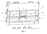
- Fig. 1 shows a part of a jetting device 1 for ejecting droplets of a relatively hot fluid, in particular a molten metal such as copper, silver, gold and the like.
- the jetting device 1 comprises a support frame 2, made of a heat resistant and preferably heat conductive material.
- the jetting device 1 is provided with an ejection nozzle 4 through which a droplet of the fluid may be ejected.
- the nozzle or orifice 4 is a through hole extending through a wall of a fluid chamber body 6.
- a fluid chamber is arranged in the fluid chamber body 6 .
- the fluid chamber is configured to hold the fluid.
- the jetting device 1 For ejecting droplets of molten metal, the jetting device 1 is provided with two permanent magnets 8a, 8b (hereinafter also referred to as magnets 8).
- the magnets 8 are arranged between two magnetic field concentrating elements 10a, 10b (hereinafter also referred to as concentrators 10) made of magnetic field guiding material such as iron.
- the jetting device 1 is further provided with two electrodes 12a, 12b (hereinafter also referred to as electrodes 12) both extending into the fluid chamber body 6 through a suitable through hole such that at least a tip of each of the electrodes 12 is in direct electrical contact with the molten metal present in the fluid chamber.
- the electrodes 12 are supported by suitable electrode supports 14 and are each operatively connectable to a suitable electrical current generator (not shown) such that a suitable electrical current may be generated through the electrodes 12 and the molten metal present between the tips of the electrodes 12.
- Fig. 2 shows a cross-section of the embodiment illustrated in Fig. 1 , which cross-section is taken along line b-b ( Fig. 1 ).
- the support frame 2 and the magnets 8 are shown.
- the support frame 2 is provided with cooling channels 34 through which a cooling liquid may flow for actively cooling of the support frame 2 and the magnets 8.
- An induction coil 24 is shown.
- the fluid chamber body 6 is arranged in a centre of the induction coil 24 such that a current flowing through the induction coil 24 results in heating of a metal arranged in the fluid chamber 6. Due to such heating the metal may melt and thus become a fluid.
- the jetting device 1 further comprises a control unit 33.
- the control unit 33 is operatively connected to the electrical alternating current generating unit 31 and the electrical direct current generating unit 32.
- Non-limiting examples of suitable electrical direct current generating units are batteries, solar cells and dynamos.
- Non-limiting examples of suitable electrical alternating current generating units are high power amplifiers or high current amplifiers.
- both the electrical alternating current generating unit 31 and the electrical direct current generating unit 32 are connected to electrodes 12.
- the direct electrical current generated by the electrical direct current generating unit 32 can be applied to the fluid present in the actuation chamber 23 through the electrodes 12.
- the amount of direct electrical current supplied to the fluid via the electrodes as well as the amount of alternating electrical current supplied to the fluid may be controlled by control unit 33.
- the control unit 33 may control the direct electrical current and the alternating electrical current such that the heat generated by the direct electrical current ( I direc t 2 * R ) is different from the alternating electrical current (( I RMS ) 2 * R ) .
- the control unit 33 is also operatively connected to the induction coil 24.
- the induction coil 24 is positioned further away from the orifice than the electrodes 12. Heating of the fluid in the fluid chamber 6 using the induction coil 24 may have less influence on the temperature of the orifice 4 as heating the fluid in the actuation chamber 23 using the electrodes. However, the induction coil 24 may assist in keeping the fluid as well as the fluid chamber body 6 around a desired temperature and keeping the fluid molten.
- Fig. 3A shows a first example of the method according to the present invention.
- Fig. 3B shows the corresponding amount of heat generated in the electrically conductive fluid by the alternating and direct electrical current.
- a plurality of direct current pulses (I direct ), also referred to as actuation pulses, is applied to the electrically conductive fluid.
- the magnitude of the current applied during each of the direct current pulses (I direct ) is equal.
- Such sequence of direct current pulses may be used for example to print a series of droplets.
- the pulse width of the direct current pulse is constant, then each of the droplets of the series of droplet may have the same volume. However, the widths of the pulse may also vary along the different pulses of direct current applied.
- a first actuation pulse is provided by applying a direct current having a magnitude of I direct .
- an amount of heat Q that equals Q actuation is generated in the electrically conductive fluid as is shown in Fig 3B .
- the first direct current pulse stops and an alternating current l alternating is applied, thereby providing a maintenance pulse.
- the alternating current is applied until t 2 .
- the magnitude of the alternating current is selected such that the amount of heat generated by the alternating current (( I RMS ) 2 * R ) is smaller than the amount of heat generated by the pulse of direct current ( I direct 2 * R ) .
- I direct 2 * R the pulse of direct current
- the amount of heat Q generated in the fluid is lowered when the direct current I direct is replaced by the alternating current I alternating .
- the alternating current I alternating is stopped and an actuation pulse is applied again.
- the magnitude of the current applied in this second direct current pulse equals the magnitude of the current applied in the first direct current pulse.
- the amount of heat Q generated in the system equals Q actuation , which is equal to the amount of heat generated during the first direct current pulse in between t 0 and t 1 .
- the second direct current pulse is stopped and an alternating current is applied.
- the amplitude of the alternating current I alternating applied in between t 3 and t 4 equals the amplitude of the alternating current I alternating applied in between t 1 and t 2 . Therefore, as is shown in Fig. 3B , the total amount of heat Q generated equals Q maintenance .
- the alternating current is stopped and a third direct current pulse is applied, the magnitude of the direct current I direct being equal to the magnitude of the direct current pulses applied in between t 0 and t 1 and in between t 2 and t 3 , respectively.
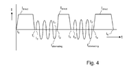
- Fig. 4 shows a second example of the method according to the present invention.
- three actuation pulses are schematically shown.
- a first actuation pulse is applied between t 0 and t 1
- a second actuation pulse is applied between t 2 and t 3
- a third actuation pulse is applied between t 4 and t 5 .
- the actuation pulses provide a certain amount of heat (not shown).
- the actuation pulses have a trapezoidal shape.
- a maintenance pulse is applied in between the first and the second actuation pulse. However, the maintenance pulse does not start at t 1 , but starts at a small time interval after the first actuation pulse is finished (t 1' ).
- a maintenance is applied by applying an alternating current.
- the alternating current is stopped.
- no pulse is applied.
- the maintenance pulse may provide an amount of heat (not shown).
- no heat is provided to the electrically conductive fluid by the pulses.
- the amount of heat supplied to the electrically conductive fluid by the (actuation and maintenance) pulse is not constant.
- a second maintenance pulse is applied. The maintenance pulse starts at t 3' , a short time interval after the second actuation pulse has stopped (t 3 ).
- a maintenance is applied by applying an alternating current.
- the alternating current is stopped.
- no pulse is applied.
- plurality is defined as two or more than two.
- another is defined as at least a second or more.
- the terms including and/or having, as used herein, are defined as comprising (i.e., open language).
- coupled is defined as connected, although not necessarily directly.
Landscapes
- Ink Jet (AREA)
Abstract
The present invention relates to a method for operating a jetting device, the jetting device being configured to expel droplets of an electrically conducting fluid. The method involves applying an actuation pulse to the electrically conductive fluid, as well as applying a maintenance pulse to the electrically conductive fluid. The present invention further relates to a jetting device for performing such method.
Description
- The present invention relates to a method for operating a jetting device. The present invention further relates to a jetting device for printing a droplet of an electrically conductive fluid.
- A jetting device for ejecting droplets of a molten metal is known. An example of a jetting device for ejecting droplets of a molten metal is described in
WO 2010/063576 A1 . In such a printing device, a Lorentz force is generated in the molten metal due to which a droplet is expelled through an orifice of the printing device. Such a device may be used to eject droplets of a molten metal at a high temperature. Hence, using such device, metals having a high melting point, such as silver, gold and copper can be jetted. - Direct printing of molten metals may be employed for printing electronic circuitry, for example. In such an application it is essential that all droplets are actually printed accurately as otherwise the electronic circuitry may not function due to an interruption in the electronic connections as a result of a missing droplet, for example. Ejection of a droplet may be hampered in case the jetting device is malfunctioning. A possible cause for malfunctioning of the jetting device is blocking of an orifice. An orifice that is blocked contains solid material that is deposited in and/ or around the orifice. The solid material may comprise e.g. contaminants present in the metal.
- When an orifice is blocked, it may be more difficult or even impossible to eject a droplet of fluid from the orifice. As a consequence, a decrease in the jetting stability may result in missing droplets. It is therefore desirable to prevent the orifice from becoming blocked.
-
EP2792490 describes a method for operating a jetting device configured to expel droplets of an electrically conductive fluid. In this method, a direct current and an alternating current are applied to the electrically conductive fluid, such that the heat generated by the direct current and the alternating current is constant. A disadvantage of this method is that a large amount of heat is supplied to the electrically conductive fluid; the amount of heat applied may not be lowered temporarily. Hence, when operating the jetting device according to the method described inEP2792490 , the jetting device is operated at high temperatures, for example more than a few hundred degrees Celsius above the melting temperature of the electrically conductive fluid. Operating the jetting device at such temperatures may have disadvantageous effects. For example, the materials of the jetting device may degrade at increased rate, which hampers stable jetting in the long term. - Therefore, it is an object of the invention to provide a method that prevents blocking of the orifice. It is a further object of the invention to provide a method that allows operating the jetting device at lower temperatures.
- It has been found that the objects of the invention can be at least partially achieved by applying a method for operating a jetting device, the jetting device being configured to expel droplets of an electrically conducting fluid wherein at least a part of the conductive fluid is positioned in a magnetic field, the method comprising the steps of:
- a) providing a first actuation pulse by providing direct electrical current in the part of the conductive fluid positioned in the magnetic field, thereby generating a Lorentz force in the conductive fluid and generating an amount of heat; and
- b) providing a second actuation pulse by providing direct electrical current in the part of the conductive fluid positioned in the magnetic field, thereby generating a Lorentz force in the conductive fluid and generating an amount of heat; and
- c) in between the first actuation pulse and the second actuation pulse, providing a maintenance pulse by providing an alternating electrical current in the part of the conductive fluid positioned in the magnetic field, the alternating electrical current generating an amount of heat;
- In a known system for printing a molten metal composition, a droplet of said metal composition is expelled through an orifice by a Lorentz force. This force causes a motion in the metal. This motion may cause a part of the molten metal to move from the fluid chamber through the orifice, thereby generating a droplet of the molten metal. The Lorentz force is related to the electric current and the magnetic field vector;
F =I ×B . The Lorentz force resulting from the electric current and the magnetic field is generated in a direction perpendicular to both the electrical current and the magnetic field. By suitably selecting the direction and the magnitude of the electric current, as well as the direction and the magnitude of the magnetic field, the direction and the magnitude of the resulting Lorentz force may be selected. In the system according to the present invention, in normal operation, the magnetic field is provided and an electrical current is provided in the molten metal composition, such that a suitable force for ejecting a droplet is generated. Thus, in the context of the present invention, the direct current pulse may be configured to actuate the electrically conductive fluid thereby generating a droplet of said fluid. The direct current pulse is also referred to as actuation pulse. Typically, when printing an image a plurality of droplets is applied onto a recording medium in a pre-determined pattern. When operating the jetting device, a first actuation pulse may be provided by applying direct electrical current in the part of the conductive fluid positioned in the magnetic field, thereby generating a Lorentz force in the conductive fluid. The first actuation pulse may result in expelling a first droplet of the electrically conductive fluid. In addition, the first actuation pulse may also generate an amount of heat. Further, when operating the jetting device, a second actuation pulse may be provided by applying direct electrical current in the part of the conductive fluid positioned in the magnetic field, thereby generating a Lorentz force in the conductive fluid. The second actuation pulse may result in expelling a second droplet of the electrically conductive fluid. In addition, the first actuation pulse may also generate an amount of heat. Optionally, a third, fourth, etc actuation pulse may be applied to the electrically conductive fluid. - There may be a time interval in between the first actuation pulse and the second actuation pulse. During this time interval, a maintenance pulse may be applied by providing an alternating electrical current in the part of the conductive fluid positioned in the magnetic field, the alternating electrical current generating an amount of heat.
- The jetting device in accordance with the present invention comprises a fluid chamber and has an orifice extending from the fluid chamber to an outer surface of the fluid chamber element. In operation, the fluid chamber comprises a molten metal composition.
- When applying an actuation pulse, a Lorentz force is generated within the metal, causing the molten metal composition to move through the orifice in a direction away from the fluid chamber. The actuation pulse may be applied by applying a pulsed magnetic field and a continuous electrical current, or a pulsed electrical current in a continuous magnetic field, or a combination thereof. Alternatively, a constant Lorentz force may be generated within the metal by applying a constant electrical current to the electrically conductive fluid in a constant magnetic field. However, application of a constant Lorentz force to the molten metal composition may result in the ejection of a stream of the electrically conductive fluid, instead of in the ejection of droplets.
- The jetting device may be positioned in an inert atmosphere, for example an inert gas such as nitrogen or a noble gas. By using an inert atmosphere, oxidation of the metal by reacting with oxygen from the air may be prevented and hence, the rate of oxidation of the metal may be decreased. However, it was found that, even if an inert atmosphere is applied, still oxidation of the metal and of impurities in the metal may occur.
- Both the actuation pulse and the maintenance pulse may generate an amount of heat. The actuation pulse is applied to the fluid by providing a direct current. The amount of heat generated by the actuation pulse per unit of time is:

- The maintenance pulse, in contrast to the actuation pulse, applies an alternating current to the electrically conductive fluid. The magnitude of the alternating current changes with time according to a sinusoidal curve. The amplitude of the sinusoidal curve is the maximum current (Imax). Furthermore, the alternating current has a root mean square current (IRMS). The average heat generated by the alternating current per unit of time equals:

- Applying a maintenance pulse may not result in ejection of a droplet. The magnitude and the direction of the alternating current changes constantly, inertia may prevent that the movement generated by the maintenance pulse may result in the ejection of a droplet through the orifice of the jetting device.
- In the method according to the present invention, the amount of heat generated by the alternating current is different from the amount of heat generated by the direct current. It was found that applying a maintenance pulse in between a first actuation pulse and a second actuation pulse improves the jetting stability. When applying the method according to the present invention, stable operation of the jetting device was observed, even at temperatures of just above the melting temperature of the electrically conductive fluid, for example less than 100°C above the melting temperature.
- In an embodiment, the amount of heat generated by the alternating current is smaller than the amount of heat generated by the direct current.
It is preferred to operate the jetting device at relatively low temperatures, as at high temperatures the materials of the jetting device may degrade at an increased rate. The jetting device may be heated during operation by the heat generated by the actuation pulses and the maintenance pulses. Optionally, other sources of heat may also influence the temperature of the jetting device.
The heat generated by the actuation pulse depends e.g. on the magnitude of the current used and the duration of the pulse. When applying an actuation pulse, a direct current is applied to the electrically conductive fluid. The magnitude of the current and the duration of the pulse may be tuned to eject a droplet of a pre-determined volume at a pre-determined speed.
In between a first and a second actuation pulse, a maintenance pulse may be applied. The maintenance pulse may be applied by applying an alternating current to the electrically conductive fluid. The magnitude of the current may be selected such that the heat generated by the alternating current is smaller than the amount of heat generated by the direct current. By limiting the amount of heat generated by the alternating current, the total amount of heat supplied to the fluid and the jetting device may be limited, allowing to operate the jetting device at relatively low temperatures. The amount of heat generated by the alternating current may be less than 90% of the heat generated by the direct current. Preferably, the amount of heat generated by the alternating current may be less than 75% of the heat generated by the direct current. More preferably, the amount of heat generated by the alternating current may be less than 50% of the heat generated by the direct current. - In an embodiment, the alternating electrical current has a frequency in the range of from 40 kHz to 500 kHz.
The frequency of the alternating current may be in the range of from 40 kHz to 500 kHz. Preferably, the frequency of the alternating current may be in the range of from 100 kHz to 400 kHz. An alternating current having a high frequency, for example a frequency in the range mentioned above, is a current having a sinusoidal curve, wherein the time in between two adjacent maxima is short. Because the high frequency alternating current quickly changes sign, the direction of the Lorentz force generated by the alternating current quickly changes.
If the direction of the Lorentz force generated would change slowly then the application of the alternating current might result in movement of the fluid leading to the ejection of a droplet. This may be undesired, because the alternating current may be configured not to actuate the electrically conductive fluid, thereby not generating a droplet of said fluid. However, due to inertia, it may take some time for the direction of the (net) movement of the fluid, induced by the Lorentz force, to change. Therefore, the faster the direction of the Lorentz force generated changes, the less likely that the alternating current will result in significant movement of the fluid within the pressure chamber. This may be beneficial for jetting stability. Furthermore, applying an alternating electrical current to the electrically conductive fluid does not need to result in the ejection of a droplet. - In an embodiment, the electrically conductive fluid is a molten metal. Molten metals may be efficiently jetted using the method according to the present invention. The molten metal may comprise e.g. silver, gold or copper. Optionally, the molten metal may comprise a mixture of molten metals.
Jetting droplets of a molten metals may be a suitable way of producing electronic circuitry. - In an aspect of the invention, a jetting device for printing a droplet of an electrically conductive fluid is provided, the jetting device comprising:
- a fluid chamber or holding an amount of the electrically conductive fluid; and
- an actuation assembly configured to expel droplets of the electrically conductive fluid from the chamber through a nozzle, the actuation assembly comprising
- ∘ a magnetic field generating unit for generating a magnetic field in at least a part of the fluid chamber; and
- ∘ an electrical direct current generating unit for generating a direct electrical current in the electrically conductive fluid in the part of the chamber provided with the magnetic field, thereby generating a pressure wave in the conductive fluid in said part of the fluid chamber,
- ∘ an electrical alternating current generating unit for generating an alternating electrical current in the electrically conductive fluid in the part of the chamber provided with the magnetic field,
- ∘ control means configured to carry out the method according to the present invention.
- The printing device according to the present invention is thus configured for performing the method according to the present invention.
- In an embodiment, the electrical direct current generating unit is operatively connectable to two electrodes in contact with the electrically conductive fluid for providing the electrical direct actuation current in the conductive fluid, the jetting device being configured such that the two electrodes are operatively connected to the electrical direct current generating unit upon actuation.
The two electrodes may both be operatively connected to electrically conductive fluid and may thereby apply the direct electrical current provided by the electrical direct current generating unit to the electrically conductive fluid. - In an embodiment, the electrical alternating current generating unit is operatively connectable to the two electrodes in contact with the electrically conductive fluid.
In this embodiment, the two electrodes may be used to apply both the direct current provided by the electrical direct current generating unit as well as the alternating current provided by the electrical alternating current generating unit to the electrically conductive fluid. The heat dissipated in a system depends e.g. on the total resistance of the several parts of the system through which a current runs, e.g. the electrode resistance, the print head material resistance, the liquid metal resistance, and contact resistances. In case the resistance of the connection between the electrical alternating current generating unit and the two electrodes is similar, preferable equal, to the resistance of the connection between the electrical direct current generating unit and the two electrodes, then the control unit may control the direct electrical current and the alternating electrical current such that Idirect and IRMS are different. Preferably, IRMS is smaller than Idirect. - These and further features and advantages of the present invention are explained hereinafter with reference to the accompanying drawings showing non-limiting embodiments and wherein:
- Fig. 1
- shows a perspective view of a printing device for printing droplets of an electrically conductive fluid.
- Fig. 2
- shows a cross-sectional view of a part of the printing device shown in
Fig. 1 . - Fig. 3A and Fig. 3B
- schematically show a first example of the method according to the present invention.
- Fig. 4
- schematically shows a second example of the method according to the present invention.
- In the drawings, same reference numerals refer to same elements.
-
Fig. 1 shows a part of ajetting device 1 for ejecting droplets of a relatively hot fluid, in particular a molten metal such as copper, silver, gold and the like. Thejetting device 1 comprises asupport frame 2, made of a heat resistant and preferably heat conductive material.
Thejetting device 1 is provided with anejection nozzle 4 through which a droplet of the fluid may be ejected. The nozzle ororifice 4 is a through hole extending through a wall of afluid chamber body 6. In the fluid chamber body 6 a fluid chamber is arranged. The fluid chamber is configured to hold the fluid.
For ejecting droplets of molten metal, thejetting device 1 is provided with twopermanent magnets magnets 8 are arranged between two magneticfield concentrating elements jetting device 1 is further provided with twoelectrodes fluid chamber body 6 through a suitable through hole such that at least a tip of each of the electrodes 12 is in direct electrical contact with the molten metal present in the fluid chamber. The electrodes 12 are supported by suitable electrode supports 14 and are each operatively connectable to a suitable electrical current generator (not shown) such that a suitable electrical current may be generated through the electrodes 12 and the molten metal present between the tips of the electrodes 12. -
Fig. 2 shows a cross-section of the embodiment illustrated inFig. 1 , which cross-section is taken along line b-b (Fig. 1 ). Referring toFig. 2 , thesupport frame 2 and themagnets 8 are shown. In the illustrated embodiment, thesupport frame 2 is provided withcooling channels 34 through which a cooling liquid may flow for actively cooling of thesupport frame 2 and themagnets 8. Aninduction coil 24 is shown. Thefluid chamber body 6 is arranged in a centre of theinduction coil 24 such that a current flowing through theinduction coil 24 results in heating of a metal arranged in thefluid chamber 6. Due to such heating the metal may melt and thus become a fluid. Such inductive heating ensures a power-efficient heating and no contact between any heating element and the fluid, limiting a number of (possible) interactions between elements of thejetting device 1 and the fluid. Nevertheless, in other embodiments, other means for heating the metal in the fluid chamber may be applied. The presence of the induction coil may help in controlling the temperature of the fluid in a position away from theorifice 4. Also, it may be useful to heat the fluid using theinduction coil 24, for example at start up of the jetting device, when the electrically conductive material is molten to become an electrically conductive fluid.
Thejetting device 1 further comprises acontrol unit 33. Thecontrol unit 33 is operatively connected to the electrical alternatingcurrent generating unit 31 and the electrical directcurrent generating unit 32. Non-limiting examples of suitable electrical direct current generating units are batteries, solar cells and dynamos. Non-limiting examples of suitable electrical alternating current generating units are high power amplifiers or high current amplifiers. In the embodiment shown inFig. 2 , both the electrical alternatingcurrent generating unit 31 and the electrical directcurrent generating unit 32 are connected to electrodes 12. Thus, the direct electrical current generated by the electrical directcurrent generating unit 32 can be applied to the fluid present in theactuation chamber 23 through the electrodes 12.The amount of direct electrical current supplied to the fluid via the electrodes as well as the amount of alternating electrical current supplied to the fluid may be controlled bycontrol unit 33. Thecontrol unit 33 may control the direct electrical current and the alternating electrical current such that the heat generated by the direct electrical current (I direct 2 * R) is different from the alternating electrical current ((IRMS )2 * R).
In the embodiment shown inFig. 2 , thecontrol unit 33 is also operatively connected to theinduction coil 24. Theinduction coil 24 is positioned further away from the orifice than the electrodes 12. Heating of the fluid in thefluid chamber 6 using theinduction coil 24 may have less influence on the temperature of theorifice 4 as heating the fluid in theactuation chamber 23 using the electrodes. However, theinduction coil 24 may assist in keeping the fluid as well as thefluid chamber body 6 around a desired temperature and keeping the fluid molten. -
Fig. 3A shows a first example of the method according to the present invention.Fig. 3B shows the corresponding amount of heat generated in the electrically conductive fluid by the alternating and direct electrical current.
In the first example, a plurality of direct current pulses (Idirect), also referred to as actuation pulses, is applied to the electrically conductive fluid. The magnitude of the current applied during each of the direct current pulses (Idirect) is equal. Such sequence of direct current pulses may be used for example to print a series of droplets. In case the pulse width of the direct current pulse is constant, then each of the droplets of the series of droplet may have the same volume. However, the widths of the pulse may also vary along the different pulses of direct current applied.
In between t0 and t1, a first actuation pulse is provided by applying a direct current having a magnitude of Idirect. As a result of this current, an amount of heat Q that equals Qactuation is generated in the electrically conductive fluid as is shown inFig 3B . At t1, the first direct current pulse stops and an alternating current lalternating is applied, thereby providing a maintenance pulse. The alternating current is applied until t2. The magnitude of the alternating current is selected such that the amount of heat generated by the alternating current ((IRMS )2 * R) is smaller than the amount of heat generated by the pulse of direct current (Idirect 2 * R). As is shown inFig. 3B , the amount of heat Q generated in the fluid is lowered when the direct current Idirect is replaced by the alternating current Ialternating. At t2, the alternating current Ialternating is stopped and an actuation pulse is applied again. The magnitude of the current applied in this second direct current pulse equals the magnitude of the current applied in the first direct current pulse. As a consequence, as is shown inFig. 3B , in between t2 and t3, the amount of heat Q generated in the system equals Qactuation, which is equal to the amount of heat generated during the first direct current pulse in between t0 and t1. At t3, the second direct current pulse is stopped and an alternating current is applied. The amplitude of the alternating current Ialternating applied in between t3 and t4 equals the amplitude of the alternating current Ialternating applied in between t1 and t2. Therefore, as is shown inFig. 3B , the total amount of heat Q generated equals Qmaintenance. At t4, the alternating current is stopped and a third direct current pulse is applied, the magnitude of the direct current Idirect being equal to the magnitude of the direct current pulses applied in between t0 and t1 and in between t2 and t3, respectively. -
Fig. 4 shows a second example of the method according to the present invention. InFig. 4 , three actuation pulses are schematically shown. A first actuation pulse is applied between t0 and t1, a second actuation pulse is applied between t2 and t3 and a third actuation pulse is applied between t4 and t5. The actuation pulses provide a certain amount of heat (not shown). In this second example, the actuation pulses have a trapezoidal shape.
In between the first and the second actuation pulse, a maintenance pulse is applied. However, the maintenance pulse does not start at t1, but starts at a small time interval after the first actuation pulse is finished (t1'). From t1' until t1", a maintenance is applied by applying an alternating current. At t1", the alternating current is stopped. In between t1" and t2, no pulse is applied. The maintenance pulse may provide an amount of heat (not shown). During the intervals wherein no pulse (actuation pulse or maintenance pulse) is applied to the electrically conductive fluid, no heat is provided to the electrically conductive fluid by the pulses. Hence, in this example, the amount of heat supplied to the electrically conductive fluid by the (actuation and maintenance) pulse is not constant.
In between the second and third actuation pulse, a second maintenance pulse is applied. The maintenance pulse starts at t3', a short time interval after the second actuation pulse has stopped (t3). From t3' until t3", a maintenance is applied by applying an alternating current. At t3", the alternating current is stopped. In between t3" and t4, no pulse is applied. - Detailed embodiments of the present invention are disclosed herein; however, it is to be understood that the disclosed embodiments are merely exemplary of the invention, which can be embodied in various forms. Therefore, specific structural and functional details disclosed herein are not to be interpreted as limiting, but merely as a basis for the claims and as a representative basis for teaching one skilled in the art to variously employ the present invention in virtually and appropriately detailed structure. In particular, features presented and described in separate dependent claims may be applied in combination and any combination of such claims are herewith disclosed. Further, the terms and phrases used herein are not intended to be limiting; but rather, to provide an understandable description of the invention. The terms "a" or "an", as used herein, are defined as one or more than one. The term plurality, as used herein, is defined as two or more than two. The term another, as used herein, is defined as at least a second or more. The terms including and/or having, as used herein, are defined as comprising (i.e., open language). The term coupled, as used herein, is defined as connected, although not necessarily directly.
Claims (7)
- Method for operating a jetting device (1), the jetting device (1) being configured to expel droplets of an electrically conducting fluid wherein at least a part of the conductive fluid is positioned in a magnetic field, the method comprising the steps of:a) providing a first actuation pulse by providing direct electrical current in the part of the conductive fluid positioned in the magnetic field, thereby generating a Lorentz force in the conductive fluid and generating an amount of heat; andb) providing a second actuation pulse by providing direct electrical current in the part of the conductive fluid positioned in the magnetic field, thereby generating a Lorentz force in the conductive fluid and generating an amount of heat; andc) in between the first actuation pulse and the second actuation pulse, providing a maintenance pulse by providing an alternating electrical current in the part of the conductive fluid positioned in the magnetic field, the alternating electrical current generating an amount of heat;wherein the amount of heat generated by the alternating current is different from the amount of heat generated by the direct current.
- Method according to claim 1, wherein the amount of heat generated by the alternating current is smaller than the amount of heat generated by the direct current.
- Method according to claim 1 or 2, wherein the alternating electrical current has a frequency in the range of from 40 kHz to 500 kHz.
- Method according to any of the preceding claims, wherein the electrically conductive fluid is a molten metal.
- Jetting device (1) for printing a droplet of an electrically conductive fluid, the jetting device (1) comprising:• a fluid chamber (23) for holding an amount of the electrically conductive fluid; and• an actuation assembly configured to expel droplets of the electrically conductive fluid from the chamber through a nozzle (4), the actuation assembly comprising∘ a magnetic field generating unit (8) for generating a magnetic field in at least a part of the fluid chamber (23); and∘ an electrical direct current generating unit (32) for generating a direct electrical current in the electrically conductive fluid in the part of the chamber (23) provided with the magnetic field, thereby generating a pressure wave in the conductive fluid in said part of the fluid chamber (23),wherein the jetting device (1) further comprises :∘ an electrical alternating current generating unit (31) for generating an alternating electrical current in the electrically conductive fluid in the part of the chamber (23) provided with the magnetic field,∘ control means (33) configured to carry out the method according to any of the claims 1-4.
- Jetting device (1) according to claim 4, wherein the electrical direct current generating unit (32) is operatively connectable to two electrodes (12a, 12b) in contact with the electrically conductive fluid for providing the electrical direct actuation current in the conductive fluid, the jetting device (1) being configured such that the two electrodes (12a, 12b) are operatively connected to the electrical direct current generating unit (32) upon actuation.
- Jetting device (1) according to claim 5, wherein the electrical alternating current generating unit (31) is operatively connectable to the two electrodes (12a, 12b) in contact with the electrically conductive fluid.
Priority Applications (1)
| Application Number | Priority Date | Filing Date | Title |
|---|---|---|---|
| EP14195047.7A EP3025863A1 (en) | 2014-11-27 | 2014-11-27 | Method for operating a jetting device |
Applications Claiming Priority (1)
| Application Number | Priority Date | Filing Date | Title |
|---|---|---|---|
| EP14195047.7A EP3025863A1 (en) | 2014-11-27 | 2014-11-27 | Method for operating a jetting device |
Publications (1)
| Publication Number | Publication Date |
|---|---|
| EP3025863A1 true EP3025863A1 (en) | 2016-06-01 |
Family
ID=52013843
Family Applications (1)
| Application Number | Title | Priority Date | Filing Date |
|---|---|---|---|
| EP14195047.7A Withdrawn EP3025863A1 (en) | 2014-11-27 | 2014-11-27 | Method for operating a jetting device |
Country Status (1)
| Country | Link |
|---|---|
| EP (1) | EP3025863A1 (en) |
Cited By (1)
| Publication number | Priority date | Publication date | Assignee | Title |
|---|---|---|---|---|
| CN117283989A (en) * | 2023-10-30 | 2023-12-26 | 武汉国创科光电装备有限公司 | Arrayed electrofluidic jet printing method and device for ink jet printing |
Citations (4)
| Publication number | Priority date | Publication date | Assignee | Title |
|---|---|---|---|---|
| JPH0274349A (en) * | 1988-09-09 | 1990-03-14 | Citizen Watch Co Ltd | Ink jet recording method and apparatus therefor |
| JP2008173770A (en) * | 2007-01-16 | 2008-07-31 | Hitachi Ltd | Conductive liquid discharge apparatus and conductive liquid discharge control method |
| WO2010063576A1 (en) | 2008-12-02 | 2010-06-10 | Oce-Technologies B.V. | Device for ejecting droplets of a fluid having a high temperature |
| EP2792490A1 (en) | 2013-04-16 | 2014-10-22 | Océ-Technologies B.V. | Method for controlling the temperature of a jetting device |
-
2014
- 2014-11-27 EP EP14195047.7A patent/EP3025863A1/en not_active Withdrawn
Patent Citations (4)
| Publication number | Priority date | Publication date | Assignee | Title |
|---|---|---|---|---|
| JPH0274349A (en) * | 1988-09-09 | 1990-03-14 | Citizen Watch Co Ltd | Ink jet recording method and apparatus therefor |
| JP2008173770A (en) * | 2007-01-16 | 2008-07-31 | Hitachi Ltd | Conductive liquid discharge apparatus and conductive liquid discharge control method |
| WO2010063576A1 (en) | 2008-12-02 | 2010-06-10 | Oce-Technologies B.V. | Device for ejecting droplets of a fluid having a high temperature |
| EP2792490A1 (en) | 2013-04-16 | 2014-10-22 | Océ-Technologies B.V. | Method for controlling the temperature of a jetting device |
Cited By (2)
| Publication number | Priority date | Publication date | Assignee | Title |
|---|---|---|---|---|
| CN117283989A (en) * | 2023-10-30 | 2023-12-26 | 武汉国创科光电装备有限公司 | Arrayed electrofluidic jet printing method and device for ink jet printing |
| CN117283989B (en) * | 2023-10-30 | 2024-06-11 | 武汉国创科光电装备有限公司 | Arrayed electrofluidic jet printing method and device for ink jet printing |
Similar Documents
| Publication | Publication Date | Title |
|---|---|---|
| EP3020257B1 (en) | Method for jetting droplets of an electrically conductive fluid and jetting device | |
| US20140217134A1 (en) | Method and system for maintaining jetting stability in a jetting device | |
| US9616494B2 (en) | Conductive liquid three dimensional printer | |
| EP2792490B1 (en) | Method for controlling the temperature of a jetting device | |
| EP2974866A1 (en) | Method for ejecting molten metals | |
| JP2014003263A (en) | Solder paste discharge device, patterning system, and control method of patterning system | |
| US9393581B2 (en) | Method for controlling the temperature of a jetting device | |
| EP3025863A1 (en) | Method for operating a jetting device | |
| US12172209B2 (en) | Printer jetting mechanism and printer employing the printer jetting mechanism | |
| US11794241B2 (en) | Method of jetting print material and method of printing | |
| JP2023048118A5 (en) | ||
| EP2933110B1 (en) | Method for ejecting molten metals | |
| JP2014100812A (en) | Ink discharge system | |
| CN108437634B (en) | Electromagnetic printing nozzle, electromagnetic printing device and printing method | |
| US12017272B2 (en) | Printer jetting mechanism and printer employing the printer jetting mechanism | |
| US11806783B2 (en) | Method of jetting print material and method of printing | |
| JP2015085513A (en) | Inkjet recording device | |
| JP2023048128A5 (en) | ||
| EP4601862A1 (en) | Titanium diboride and tungsten copper terminals for jetting of liquid aluminum | |
| EP3196024A1 (en) | Method of controlling a temperature in a jetting device | |
| JP2003318528A (en) | Liquid metal or viscous liquid supply device |
Legal Events
| Date | Code | Title | Description |
|---|---|---|---|
| PUAI | Public reference made under article 153(3) epc to a published international application that has entered the european phase |
Free format text: ORIGINAL CODE: 0009012 |
|
| AK | Designated contracting states |
Kind code of ref document: A1 Designated state(s): AL AT BE BG CH CY CZ DE DK EE ES FI FR GB GR HR HU IE IS IT LI LT LU LV MC MK MT NL NO PL PT RO RS SE SI SK SM TR |
|
| AX | Request for extension of the european patent |
Extension state: BA ME |
|
| STAA | Information on the status of an ep patent application or granted ep patent |
Free format text: STATUS: THE APPLICATION HAS BEEN WITHDRAWN |
|
| 18W | Application withdrawn |
Effective date: 20160616 |