EP3025851B1 - Bead-apex assembly system - Google Patents
Bead-apex assembly system Download PDFInfo
- Publication number
- EP3025851B1 EP3025851B1 EP15196096.0A EP15196096A EP3025851B1 EP 3025851 B1 EP3025851 B1 EP 3025851B1 EP 15196096 A EP15196096 A EP 15196096A EP 3025851 B1 EP3025851 B1 EP 3025851B1
- Authority
- EP
- European Patent Office
- Prior art keywords
- bead
- apex
- assembly
- ring
- former
- Prior art date
- Legal status (The legal status is an assumption and is not a legal conclusion. Google has not performed a legal analysis and makes no representation as to the accuracy of the status listed.)
- Not-in-force
Links
- 239000011324 bead Substances 0.000 claims description 178
- 238000000034 method Methods 0.000 claims description 14
- 238000000926 separation method Methods 0.000 claims description 13
- 239000000945 filler Substances 0.000 description 19
- 230000000712 assembly Effects 0.000 description 16
- 238000000429 assembly Methods 0.000 description 16
- 230000015572 biosynthetic process Effects 0.000 description 16
- 238000004891 communication Methods 0.000 description 8
- 230000008569 process Effects 0.000 description 6
- 238000004804 winding Methods 0.000 description 5
- 238000005516 engineering process Methods 0.000 description 3
- 239000000463 material Substances 0.000 description 3
- 230000008878 coupling Effects 0.000 description 2
- 238000010168 coupling process Methods 0.000 description 2
- 238000005859 coupling reaction Methods 0.000 description 2
- 238000007599 discharging Methods 0.000 description 2
- 238000010070 extrusion (rubber) Methods 0.000 description 2
- 238000004519 manufacturing process Methods 0.000 description 2
- 239000002184 metal Substances 0.000 description 2
- 238000005452 bending Methods 0.000 description 1
- 150000001875 compounds Chemical class 0.000 description 1
- 230000003247 decreasing effect Effects 0.000 description 1
- 230000001419 dependent effect Effects 0.000 description 1
- 230000000694 effects Effects 0.000 description 1
- 239000013536 elastomeric material Substances 0.000 description 1
- 238000001125 extrusion Methods 0.000 description 1
- 239000012530 fluid Substances 0.000 description 1
- 230000006872 improvement Effects 0.000 description 1
- 230000003993 interaction Effects 0.000 description 1
- 230000007246 mechanism Effects 0.000 description 1
- 238000005086 pumping Methods 0.000 description 1
- 238000004826 seaming Methods 0.000 description 1
- 230000007480 spreading Effects 0.000 description 1
- 229920002994 synthetic fiber Polymers 0.000 description 1
Images



Classifications
-
- B—PERFORMING OPERATIONS; TRANSPORTING
- B05—SPRAYING OR ATOMISING IN GENERAL; APPLYING FLUENT MATERIALS TO SURFACES, IN GENERAL
- B05D—PROCESSES FOR APPLYING FLUENT MATERIALS TO SURFACES, IN GENERAL
- B05D1/00—Processes for applying liquids or other fluent materials
- B05D1/36—Successively applying liquids or other fluent materials, e.g. without intermediate treatment
-
- B—PERFORMING OPERATIONS; TRANSPORTING
- B29—WORKING OF PLASTICS; WORKING OF SUBSTANCES IN A PLASTIC STATE IN GENERAL
- B29D—PRODUCING PARTICULAR ARTICLES FROM PLASTICS OR FROM SUBSTANCES IN A PLASTIC STATE
- B29D30/00—Producing pneumatic or solid tyres or parts thereof
- B29D30/06—Pneumatic tyres or parts thereof (e.g. produced by casting, moulding, compression moulding, injection moulding, centrifugal casting)
- B29D30/48—Bead-rings or bead-cores; Treatment thereof prior to building the tyre
-
- B—PERFORMING OPERATIONS; TRANSPORTING
- B05—SPRAYING OR ATOMISING IN GENERAL; APPLYING FLUENT MATERIALS TO SURFACES, IN GENERAL
- B05C—APPARATUS FOR APPLYING FLUENT MATERIALS TO SURFACES, IN GENERAL
- B05C21/00—Accessories or implements for use in connection with applying liquids or other fluent materials to surfaces, not provided for in groups B05C1/00 - B05C19/00
-
- B—PERFORMING OPERATIONS; TRANSPORTING
- B29—WORKING OF PLASTICS; WORKING OF SUBSTANCES IN A PLASTIC STATE IN GENERAL
- B29C—SHAPING OR JOINING OF PLASTICS; SHAPING OF MATERIAL IN A PLASTIC STATE, NOT OTHERWISE PROVIDED FOR; AFTER-TREATMENT OF THE SHAPED PRODUCTS, e.g. REPAIRING
- B29C65/00—Joining or sealing of preformed parts, e.g. welding of plastics materials; Apparatus therefor
- B29C65/48—Joining or sealing of preformed parts, e.g. welding of plastics materials; Apparatus therefor using adhesives, i.e. using supplementary joining material; solvent bonding
- B29C65/52—Joining or sealing of preformed parts, e.g. welding of plastics materials; Apparatus therefor using adhesives, i.e. using supplementary joining material; solvent bonding characterised by the way of applying the adhesive
-
- B—PERFORMING OPERATIONS; TRANSPORTING
- B29—WORKING OF PLASTICS; WORKING OF SUBSTANCES IN A PLASTIC STATE IN GENERAL
- B29D—PRODUCING PARTICULAR ARTICLES FROM PLASTICS OR FROM SUBSTANCES IN A PLASTIC STATE
- B29D30/00—Producing pneumatic or solid tyres or parts thereof
- B29D30/0016—Handling tyres or parts thereof, e.g. supplying, storing, conveying
- B29D2030/0044—Handling tyre beads, e.g., storing, transporting, transferring and supplying to the toroidal support or to the drum
-
- B—PERFORMING OPERATIONS; TRANSPORTING
- B29—WORKING OF PLASTICS; WORKING OF SUBSTANCES IN A PLASTIC STATE IN GENERAL
- B29D—PRODUCING PARTICULAR ARTICLES FROM PLASTICS OR FROM SUBSTANCES IN A PLASTIC STATE
- B29D30/00—Producing pneumatic or solid tyres or parts thereof
- B29D30/06—Pneumatic tyres or parts thereof (e.g. produced by casting, moulding, compression moulding, injection moulding, centrifugal casting)
- B29D30/48—Bead-rings or bead-cores; Treatment thereof prior to building the tyre
- B29D2030/482—Applying fillers or apexes to bead cores
-
- B—PERFORMING OPERATIONS; TRANSPORTING
- B29—WORKING OF PLASTICS; WORKING OF SUBSTANCES IN A PLASTIC STATE IN GENERAL
- B29D—PRODUCING PARTICULAR ARTICLES FROM PLASTICS OR FROM SUBSTANCES IN A PLASTIC STATE
- B29D30/00—Producing pneumatic or solid tyres or parts thereof
- B29D30/06—Pneumatic tyres or parts thereof (e.g. produced by casting, moulding, compression moulding, injection moulding, centrifugal casting)
- B29D30/48—Bead-rings or bead-cores; Treatment thereof prior to building the tyre
- B29D2030/487—Forming devices for manufacturing the beads
Definitions
- a vehicle tire generally has two annular bead rings at the innermost diameter, which provides the tire with hoop strength and structural integrity.
- the bead rings also provide stiffness at the point where the tire mounts to a rim.
- Bead rings are generally manufactured by winding metal wire in a groove on the outer periphery of a chuck or drum.
- Existing equipment is capable of forming a plurality of bead rings on the outer periphery of a single chuck or drum at once.
- bead rings may be formed on equipment incorporating components from commercially available products such as the SWS-6000 Bead Winding System or the SWS-4000T Bead Winding System, each of which are manufactured by Bartell Machinery Systems, L.L.C. of Rome, New York.
- the bead ring is often attached to a strip made of rubber or another synthetic material.
- This strip is generally called an apex or filler.
- the apex or filler generally is applied to the outer periphery of the bead ring and provides a smooth transitional juncture between each bead and the adjacent side wall of the vehicle tire.
- An apex is generally applied to a bead ring through the use of automatic rubber extrusion and profiling equipment and equipment for wrapping the apex or filler around the bead ring and seaming the two free ends of the strip together.
- WO 92/11131 discloses an apparatus for manufacturing an assembly of an annular bead wire core and a surrounding ring of filler material attached thereto comprising at least one former, typically mounted on a turntable, and a number of stations.
- rubber-coated bead wire is wound around the former to produce the annular bead wire core.
- the ring of filler material is arranged over the previously wound rubber-coated wire core to form the bead core assembly and at a third station the head core assembly is unloaded from the former.
- the former is moved from station to station by indexing movement of the turntable.
- the interaction between the elastomeric strip and the nip effects rotary motion of the elastomeric strip and increases the circumferential length of the elastomeric strip proportionally to the radial distance outwardly from the base thereof.
- the apex forming mechanism is operative in conjunction with an apex filler applying apparatus to apply the apex filler formed from the elastomeric strip onto the radially outer surface of a bead ring sub-assembly.
- Mounting chucks are provided to position and rotatably support the bead ring sub-assembly while the apex filler is applied thereto.
- US 4,354,892 discloses an apparatus for automatically filling a vehicle tire bead-core with an elastomeric filler having one or more drums, for encasing the bead-core in which the filler is applied when the drum rotates around its own axis.
- the apparatus is provided with means suitable for stretching the filler when it is pulled into rotation with the bead-core on the drum to stiffen the filler and resist bending, and therefore maintain the filler substantially in the drum midline.
- the apparatus is further provided with means for discharging the bead-core/filler assembly in a plane unchanged with respect to that determined by the stretching means in order to permit the collection of the various filler/bead-core assemblies one after the other.
- US 2013/0341827 discloses an apparatus for manufacturing an annular bead core-apex subassembly comprising a first station having a first support surface and a second station having a second support surface.
- the first support surface is mounted to a first support element and is rotatable on the first support element.
- the second support surface is mounted to a second support element and is rotatable on the second support element.
- the apparatus comprises a moving device for moving the first support surface from a first location to a second location and for moving the second support surface from the second location to either the first location or to another location.
- the apparatus comprises at least one handling device selected from a loading device or an unloading device, and a first nozzle in fluid communication with a first pumping or extrusion device for discharging a rubber compound.
- a bead-apex assembly system comprises a bead forming system, an apex application system, and a supporting assembly.
- the supporting assembly is located at least partially between the bead forming system and the apex application system.
- the supporting assembly is adapted to move an annular bead ring from the bead forming system to the apex application system.
- the bead-apex assembly system may comprise a plurality of apex application systems.
- the system is adapted such that when the annular bead ring is moved from the bead forming system to the apex application system, the annular bead ring moves less than fifty feet or less than fifteen metres.
- the supporting assembly may comprise a rotatable arm coupled to a first chuck.
- the rotatable arm may further comprise a first end and a second end, the first end coupled to the first chuck, and the second end coupled to a second chuck.
- a bead-apex assembly system which comprises an apex application system and a bead forming system comprising a bead former.
- the bead forming system is adapted to form an annular bead ring on the bead former
- the apex application system is adapted to apply an apex to the annular bead ring while on the bead former.
- a method for assembling a bead-apex assembly comprises: forming an annular bead ring on a bead former; loading the annular bead ring onto a supporting assembly; moving the annular bead ring to a position for engagement with an apex-application system; and applying an apex onto the outer periphery of the annular bead ring.
- the annular bead ring may be positioned by a separation system for automatic loading onto the supporting assembly.
- the separation system may be adapted for separating a plurality of annular bead rings for loading onto a plurality of supporting assemblies.
- the annular bead ring may be loaded onto the supporting assembly automatically.
- the annular bead ring may move less than fifteen metres.
- the present embodiments generally relate to bead-apex assembly systems comprising a bead forming system and an apex application system.
- the bead forming system is adapted to form annular bead rings 60.
- the apex application system is adapted to form a rubber apex 61 and to apply the rubber apex 61 to an outer periphery of bead ring 60 to form bead-apex assembly 65.
- Each of the embodiments described herein is advantageous over previously-known systems for forming bead-apex assemblies, which generally encompass significant separation of the location and processes of bead formation and apex application.
- the embodiments described herein advantageously can increase productivity, increase quality due to higher repeatability, reduce overall floor space required for the formation of bead-apex assemblies 65, and reduce the amount of inventoried product.
- a first embodiment of a bead-apex assembly system 20 comprises wire handling system 35, bead forming system 30, apex application system 40, and chuck supporting assembly 50.
- Wire handling system 35 may be adapted to feed metal wire to bead forming system 30, and may comprise wire extruding equipment, tension-controlling equipment, and the like.
- Bead forming system 30 generally comprises equipment and technology for the formation of annular bead ring 60, and may incorporate components from commercially available products such as the SWS-6000 Bead Winding System or the SWS-4000T Bead Winding System, each of which are manufactured by Bartell Machinery Systems, L.L.C. of Rome, New York. However, it will be appreciated that other bead formation technology may be used besides these exemplary two systems to assist in formation of bead rings 60.
- bead forming system 30 operates to form an annular bead ring 60 on bead former 31 at Position A.
- Bead forming system 30 may form at least one bead ring 60 on bead former 31.
- Bead ring 60 then may be transferred from the bead former 31 at Position A to Position C, where it is loaded onto chuck supporting assembly 50.
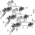
- an exemplary chuck supporting assembly 50A comprises turret arm 55 with a first end 56 and a second end 57, and rotation system 58.
- Turret arm 55 is rotatable with respect to bead forming system 30 (shown in FIG. 1 ) and apex application system 40A, with rotation system 58 providing the rotational motion.
- Rotation system 58 is depicted in FIG. 2 as an electric motor with an output shaft coupled to turret arm 55, but alternatively may be any other suitable system for moving bead rings 60.
- Chuck supporting assembly 50A additionally comprises at least one supporting chuck 51.
- supporting chuck 51 is a center expanding chuck for gripping a bead ring 60 as disclosed by U.S. Patent Application Publication No. 2014/0265400 A1 to Gorham ("Gorham").
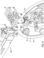
- a plurality of chuck arms 52 are adapted to move radially outward to grip an inner surface of annular bead ring 60, thereby coupling bead ring 60 to turret arm 55.
- Turret arm 55 may then rotate to move loaded bead ring 60 to Position B for communication with apex application system 40A.
- Apex application system 40A is a system for applying an apex 61 to bead ring 60 to form bead-apex assembly 65.
- Apex application system 40A generally comprises equipment for the formation of apex 61, for example through the use of automatic rubber extrusion and profiling equipment.
- apex application system 40A comprises equipment, shown as apex applicator 42, for applying apex 61 to the outer periphery of the bead ring 60.
- Apex application system 40A may incorporate components from commercially available apex application systems to the extent it relates to coupling an apex around a bead ring and securing the free ends of the apex.
- apex application system 40A may comprise additional or modified equipment relative to existing technology, including but not limited to arm 41, which is adjustable or extendable to position apex applicator 42 within proper communication with bead ring 60, for purposes described in greater detail below.
- turret arm 55 may be adjustable or extendable to position bead ring 60 in communication with apex applicator 42 at Position B.
- apex application system 40A may comprise the arm 41 that is adjustable or extendable to position apex applicator 42 within proper communication with bead ring 60. The apex 61 then may be applied to the outer periphery of the bead ring 60.
- turret arm 55 may then rotate to position the supporting chuck 51 at Position C for unloading.
- Bead-apex assembly 65 may be either automatically or manually unloaded from supporting chuck 51 at this position. Alternatively, the bead-apex assembly 65 may be unloaded at any position within the reach of the chuck supporting assembly 50A.
- the chuck supporting assembly 50A may comprise multiple supporting chucks 51, 51'.
- the first end 56 of the turret arm 55 is coupled to the supporting chuck 51 and the second end 57 is coupled to the supporting chuck 51'.
- Turret arm 55 when positioned as depicted by FIG. 2 , positions one supporting chuck 51, preferably loaded with bead ring 60, at a Position B for communication with apex application system 40A. As shown, turret arm 55 simultaneously positions a second supporting chuck 51' at Position C for the respective loading or unloading of bead rings 60 or bead-apex assemblies 65.
- Turret arm 55 may be rotated to selectively position supporting chucks 51, 51' at Position A, Position B, Position C, or any other position within reach of chuck supporting assembly 50A.
- the current embodiment is advantageous because the loading of bead ring 60 and unloading of bead-apex assembly 65 may be performed simultaneously with the formation of bead-apex assembly 65, thereby saving time and increasing the efficiency of the process.
- chuck supporting assembly 50A may comprise a plurality of turret arms, each arm comprising at least one end portion coupled to a supporting chuck 51.
- Another alternative embodies a rotatable body adapted to couple to a plurality of supporting chucks 51.
- bead-apex assembly system 20 may comprise a plurality of chuck supporting assemblies, as best shown by the embodiment of FIG. 2 incorporating three chuck supporting assemblies 50A, 50B, 50C. Such an embodiment is advantageous when it is desired to form multiple bead-apex assemblies at once.
- three chuck supporting assemblies 50A, 50B, 50C correspond with three apex application systems 40A, 40B, 40C.
- the bead-apex assembly system 20 may comprise a separation system 70 adapted for positioning bead rings 60 (not shown in FIG. 4 ) for loading on to a plurality of supporting assemblies 50A, 50B, 50C (as depicted by FIG. 2 ).
- a separation system 70 is advantageous when a plurality of bead rings 60 are formed on bead former 31 (see FIG. 1 ) in parallel and relatively close together.
- Separation system 70 may be an accordion-type spreading device comprising a plurality of gripping elements 71. Gripping elements 71 may be positioned relatively close together in a first state, as depicted in FIG.
- Separation system 70 may be further moveable and adapted to unload formed bead rings 60 from bead former 31 (see FIG. 1 ) and transport bead rings 60 to a position for loading onto chuck supporting assembly 50.
- bead forming system 30 and the apex application system 40A advantageously are in relatively close proximity. Further, the handling and transfer of bead ring 60 is substantially automated, thereby decreasing the need for human labor and increasing repeatability.
- the bead ring 60 does not travel far between bead forming and apex application.
- the bead ring 60 travels less than fifty feet or less than fifteen metres between the bead forming and apex application locations, e.g., bead former 31 to apex applicator 42.
- the bead ring 60 can travel less than twenty feet or less than six metres between the bead former 31 to apex applicator 42.
- Such a small travel distance of less than fifty feet or less than fifteen metres, or even less than twenty feet or less than six metres, is possible with the arrangement of the present embodiments and provides a significant improvement over previous arrangements where a considerably longer travel distance occurs, e.g., often across the length of an entire factory or different facilities altogether between these particular bead forming and apex applicator steps. It will also be appreciated that many handling steps are reduced or eliminated by the embodiment of FIGS. 1-5 , and the processes of bead formation and apex application may be done at substantially the same time.
- an alternative bead-apex assembly system 120 is similar to the bead-apex assembly system 20 of FIG. 1 , but not forming part of the invention, with main differences noted below.
- the bead-apex assembly 120 comprises bead forming System 130 with a bead former 131.
- Bead forming system 130 operates to form an annular bead ring 60 on bead former 131 at Position A.
- Bead forming system 130 may form a plurality of bead rings 60 on bead former 131 simultaneously.
- bead-apex assembly system 120 comprises chuck supporting assembly 150 for the supporting and transporting of bead former 131.
- chuck supporting assembly 150 moves loaded bead former 131 from a bead formation position (Position A) to an apex application position (Position B), where bead former 131 may communicate with the apex application system 140.
- Apex application system 140 may be adapted for the proper communication with bead former 131, thereby applying apex 61 to bead ring 60 to form bead-apex assembly 65 on bead former 131.
- chuck supporting assembly 150 may move bead former 131 to a position for unloading.
- the unloading position may be at any position within the reach of chuck supporting assembly 150, including the position where beads 60 are formed (Position A). If required, unloaded bead former 131 may be transported back to Position A for use during the formation of one or more bead rings 60.
- chuck supporting assembly 150 may support a plurality of bead formers 131 at once, thereby allowing for the supporting of a plurality of bead rings 60 and bead-apex assemblies 65 at once.
- Bead-apex assembly system 120 can also include multiple parallel chuck supporting assemblies, in a spacing manner similar to what is depicted in FIG. 2 above, thereby allowing for multiple parallel apex application systems to form multiple bead-apex assemblies 65 at once.
- bead forming system 120 and apex application system 140 are in close proximity, and the transport distance of bead former 131 is small, preferably less than fifty feet or less than fifteen metres, or even less than twenty feet or less than six metres, as explained above with respect to the embodiment of FIGS. 1-5 .
- an alternative bead-apex assembly system 220 comprises wire handling equipment 235, bead forming system 230, transfer shuttle system 250, and apex application system 240.
- Bead forming system 230 operates to form an annular bead ring 60 on bead former 231 at Position A.
- Bead forming system 230 may form a plurality of bead rings 60 on bead former 231 simultaneously.
- the transfer shuttle system 250 is used for the transfer of bead former 231 from a bead formation position (Position A) to an apex application position (Position B), as shown between FIGS. 7A-7B .
- Apex application system 240 may also be adapted for proper communication with bead former 231, for example, as explained with respect to FIG. 1 , above.
- apex application system 240 forms and applies apex 61 to bead ring 60, forming bead-apex assembly 65.
- Bead-apex assembly 65 may be unloaded automatically or manually at any position along transfer shuttle system 250. If required, unloaded bead former 231 may be transferred by the transfer shuttle system 250 back to Position A for use during the formation of additional bead rings 60, as generally depicted in FIG. 7C .
- Transfer shuttle system 250 may comprise equipment for moving bead former 231, including, for example, a linear actuator operated using pneumatic or hydraulic actuators, or the like.
- the transfer distance of bead ring 60 on bead former 231 is small (between the bead forming step and the apex application step), preferably less than fifty feet or less than fifteen metres, or even less than twenty feet or less than six metres, as explained above.
- a further alternative bead-apex assembly system 320 comprises bead forming system 330 and apex application system 340.
- Bead forming system 330 forms bead rings 60 on bead former 331, and may form a plurality of bead rings 60 on bead former 331 simultaneously, as generally described above.
- Apex application system 340 comprises arm 341 and apex applicator 342. After formation of a bead ring 60, an actuation system coupled to arm 341 moves the apex applicator 342 into a position such that it may engage with bead ring 60 to apply apex 61 to form bead-apex assembly 65.
- bead-apex assembly system 320 may include a plurality of movable apex applicators 342 for the formation of multiple bead-apex assemblies 65 at once. This is advantageous because it removes the need for unloading equipment to unload and separate bead rings 60, thereby saving space, time, and reducing costs. Unlike the system of claim 1, the bead ring 60 stays in substantially the same location during the bead forming process and the apex application process.
Landscapes
- Engineering & Computer Science (AREA)
- Mechanical Engineering (AREA)
- Tyre Moulding (AREA)
Description
- A vehicle tire generally has two annular bead rings at the innermost diameter, which provides the tire with hoop strength and structural integrity. The bead rings also provide stiffness at the point where the tire mounts to a rim. Bead rings are generally manufactured by winding metal wire in a groove on the outer periphery of a chuck or drum. Existing equipment is capable of forming a plurality of bead rings on the outer periphery of a single chuck or drum at once. For example, bead rings may be formed on equipment incorporating components from commercially available products such as the SWS-6000 Bead Winding System or the SWS-4000T Bead Winding System, each of which are manufactured by Bartell Machinery Systems, L.L.C. of Rome, New York.
- The bead ring is often attached to a strip made of rubber or another synthetic material. This strip is generally called an apex or filler. The apex or filler generally is applied to the outer periphery of the bead ring and provides a smooth transitional juncture between each bead and the adjacent side wall of the vehicle tire. An apex is generally applied to a bead ring through the use of automatic rubber extrusion and profiling equipment and equipment for wrapping the apex or filler around the bead ring and seaming the two free ends of the strip together.
- Currently, the processes of forming a bead ring and applying an apex or filler to form a bead-apex assembly are distinct and performed on separate equipment. This causes significant material handling and inventory burdens, and significant labor is needed to unload bead rings from bead forming equipment and load them onto apex application equipment. Further, a high degree of repeatability is difficult to achieve due to human involvement in unloading, loading, and transfer between equipment. Separate equipment also consumes a significant amount of floor space.
- Reference is directed to
WO 92/11131 - Reference is further directed to
US 5,100,497 which discloses a method and apparatus that is adapted for applying an apex filler onto a bead ring sub-assembly without the introduction of stresses at the outer edge of the apex filler. The apex filler forming apparatus works in conjunction with an extruder which presents a linear strip of elastomeric material having a pre-determined cross-section. A pair of opposed, forming rollers present a nip therebetween. Means are provided to rotate the rollers. Rotation of the forming rollers causes the nip frictionally to engage the elastomeric strip. The interaction between the elastomeric strip and the nip effects rotary motion of the elastomeric strip and increases the circumferential length of the elastomeric strip proportionally to the radial distance outwardly from the base thereof. The apex forming mechanism is operative in conjunction with an apex filler applying apparatus to apply the apex filler formed from the elastomeric strip onto the radially outer surface of a bead ring sub-assembly. Mounting chucks are provided to position and rotatably support the bead ring sub-assembly while the apex filler is applied thereto. - Reference is further directed to
US 4,354,892 which discloses an apparatus for automatically filling a vehicle tire bead-core with an elastomeric filler having one or more drums, for encasing the bead-core in which the filler is applied when the drum rotates around its own axis. The apparatus is provided with means suitable for stretching the filler when it is pulled into rotation with the bead-core on the drum to stiffen the filler and resist bending, and therefore maintain the filler substantially in the drum midline. The apparatus is further provided with means for discharging the bead-core/filler assembly in a plane unchanged with respect to that determined by the stretching means in order to permit the collection of the various filler/bead-core assemblies one after the other. - Reference is further directed to
US 2013/0341827 which discloses an apparatus for manufacturing an annular bead core-apex subassembly comprising a first station having a first support surface and a second station having a second support surface. The first support surface is mounted to a first support element and is rotatable on the first support element. The second support surface is mounted to a second support element and is rotatable on the second support element. The apparatus comprises a moving device for moving the first support surface from a first location to a second location and for moving the second support surface from the second location to either the first location or to another location. The apparatus comprises at least one handling device selected from a loading device or an unloading device, and a first nozzle in fluid communication with a first pumping or extrusion device for discharging a rubber compound. - An aspect of the invention is set out in claim 1. Embodiments are set out in the dependent claims. A bead-apex assembly system comprises a bead forming system, an apex application system, and a supporting assembly. The supporting assembly is located at least partially between the bead forming system and the apex application system. The supporting assembly is adapted to move an annular bead ring from the bead forming system to the apex application system. Optionally, the bead-apex assembly system may comprise a plurality of apex application systems.
- In one example, the system is adapted such that when the annular bead ring is moved from the bead forming system to the apex application system, the annular bead ring moves less than fifty feet or less than fifteen metres.
- The supporting assembly may comprise a rotatable arm coupled to a first chuck. The rotatable arm may further comprise a first end and a second end, the first end coupled to the first chuck, and the second end coupled to a second chuck.
- Also described herein is a bead-apex assembly system which comprises an apex application system and a bead forming system comprising a bead former. The bead forming system is adapted to form an annular bead ring on the bead former, and the apex application system is adapted to apply an apex to the annular bead ring while on the bead former. A method for assembling a bead-apex assembly is also described, this method comprises: forming an annular bead ring on a bead former; loading the annular bead ring onto a supporting assembly; moving the annular bead ring to a position for engagement with an apex-application system; and applying an apex onto the outer periphery of the annular bead ring. The annular bead ring may be positioned by a separation system for automatic loading onto the supporting assembly. The separation system may be adapted for separating a plurality of annular bead rings for loading onto a plurality of supporting
assemblies. The annular bead ring may be loaded onto the supporting assembly automatically. The annular bead ring may move less than fifteen metres. - Other systems, methods, features, and advantages will be, or will become, apparent to one with skill in the art upon examination of the following figures and detailed description.
- The invention can be better understood with reference to the following drawings and description. The components in the figures are not necessarily to scale, emphasis instead being placed upon illustrating the principles of the invention. Moreover, in the figures, like referenced numerals designated corresponding parts throughout the different views.
-
FIG. 1 is a side view of a first embodiment of an exemplary bead-apex assembly system. -
FIG. 2 is a perspective view of three parallel chuck supporting assemblies and three corresponding apex application systems comprising apex applicators. -
FIG. 3 is a perspective view showing features of an exemplary apex application. -
FIG. 4 is a perspective view of a separation system with gripping elements located relatively close together. -
FIG. 5 is a perspective view of the separation system ofFIG. 4 with the gripping elements separated. -
FIG. 6 is a side view of a bead-apex assembly system. -
FIGS. 7A-7C are side views of a bead-apex assembly system, with an exemplary sequential positioning of a bead former shown. -
FIG. 8 is a side view of a bead-apex assembly system. - The present embodiments generally relate to bead-apex assembly systems comprising a bead forming system and an apex application system. The bead forming system is adapted to form annular bead rings 60. The apex application system is adapted to form a
rubber apex 61 and to apply therubber apex 61 to an outer periphery ofbead ring 60 to form bead-apex assembly 65. Each of the embodiments described herein is advantageous over previously-known systems for forming bead-apex assemblies, which generally encompass significant separation of the location and processes of bead formation and apex application. The embodiments described herein advantageously can increase productivity, increase quality due to higher repeatability, reduce overall floor space required for the formation of bead-apex assemblies 65, and reduce the amount of inventoried product. - Referring to
FIG. 1 , a first embodiment of a bead-apex assembly system 20 compriseswire handling system 35,bead forming system 30,apex application system 40, andchuck supporting assembly 50.Wire handling system 35 may be adapted to feed metal wire to bead formingsystem 30, and may comprise wire extruding equipment, tension-controlling equipment, and the like. Bead formingsystem 30 generally comprises equipment and technology for the formation ofannular bead ring 60, and may incorporate components from commercially available products such as the SWS-6000 Bead Winding System or the SWS-4000T Bead Winding System, each of which are manufactured by Bartell Machinery Systems, L.L.C. of Rome, New York. However, it will be appreciated that other bead formation technology may be used besides these exemplary two systems to assist in formation of bead rings 60. - In the embodiment of
FIG. 1 ,bead forming system 30 operates to form anannular bead ring 60 on bead former 31 at Position A.Bead forming system 30 may form at least onebead ring 60 on bead former 31.Bead ring 60 then may be transferred from the bead former 31 at Position A to Position C, where it is loaded ontochuck supporting assembly 50. - Referring to
FIG. 2 , an exemplary chuck supporting assembly 50A comprisesturret arm 55 with a first end 56 and asecond end 57, androtation system 58.Turret arm 55 is rotatable with respect to bead forming system 30 (shown inFIG. 1 ) andapex application system 40A, withrotation system 58 providing the rotational motion.Rotation system 58 is depicted inFIG. 2 as an electric motor with an output shaft coupled toturret arm 55, but alternatively may be any other suitable system for moving bead rings 60. Chuck supporting assembly 50A additionally comprises at least one supportingchuck 51. In one example, supportingchuck 51 is a center expanding chuck for gripping abead ring 60 as disclosed byU.S. Patent Application Publication No. 2014/0265400 A1 to Gorham ("Gorham"). - As best shown by
FIG. 3 , and in a manner similar to Gorham, a plurality ofchuck arms 52 are adapted to move radially outward to grip an inner surface ofannular bead ring 60, thereby couplingbead ring 60 toturret arm 55.Turret arm 55 may then rotate to move loadedbead ring 60 to Position B for communication withapex application system 40A. -
Apex application system 40A is a system for applying an apex 61 to beadring 60 to form bead-apex assembly 65.Apex application system 40A generally comprises equipment for the formation ofapex 61, for example through the use of automatic rubber extrusion and profiling equipment. Further,apex application system 40A comprises equipment, shown asapex applicator 42, for applyingapex 61 to the outer periphery of thebead ring 60. -
Apex application system 40A may incorporate components from commercially available apex application systems to the extent it relates to coupling an apex around a bead ring and securing the free ends of the apex. However, in the present embodiments,apex application system 40A may comprise additional or modified equipment relative to existing technology, including but not limited toarm 41, which is adjustable or extendable to positionapex applicator 42 within proper communication withbead ring 60, for purposes described in greater detail below. - Referring back to
FIG. 2 ,turret arm 55 may be adjustable or extendable to positionbead ring 60 in communication withapex applicator 42 at Position B. Alternatively, or in addition,apex application system 40A may comprise thearm 41 that is adjustable or extendable to positionapex applicator 42 within proper communication withbead ring 60. The apex 61 then may be applied to the outer periphery of thebead ring 60. - After formation of bead-
apex assembly 65,turret arm 55 may then rotate to position the supportingchuck 51 at Position C for unloading. Bead-apex assembly 65 may be either automatically or manually unloaded from supportingchuck 51 at this position. Alternatively, the bead-apex assembly 65 may be unloaded at any position within the reach of the chuck supporting assembly 50A. - The chuck supporting assembly 50A may comprise multiple supporting
chucks 51, 51'. In the embodiment shown inFIGS. 1-2 , the first end 56 of theturret arm 55 is coupled to the supportingchuck 51 and thesecond end 57 is coupled to the supporting chuck 51'.Turret arm 55, when positioned as depicted byFIG. 2 , positions one supportingchuck 51, preferably loaded withbead ring 60, at a Position B for communication withapex application system 40A. As shown,turret arm 55 simultaneously positions a second supporting chuck 51' at Position C for the respective loading or unloading of bead rings 60 or bead-apex assemblies 65.Turret arm 55 may be rotated to selectively position supportingchucks 51, 51' at Position A, Position B, Position C, or any other position within reach of chuck supporting assembly 50A. The current embodiment is advantageous because the loading ofbead ring 60 and unloading of bead-apex assembly 65 may be performed simultaneously with the formation of bead-apex assembly 65, thereby saving time and increasing the efficiency of the process. - Alternatively, chuck supporting assembly 50A may comprise a plurality of turret arms, each arm comprising at least one end portion coupled to a supporting
chuck 51. Another alternative embodies a rotatable body adapted to couple to a plurality of supportingchucks 51. These embodiments are advantageous when it is desired to have more than two supporting chucks for the selective positioning of a plurality of bead rings 60 and bead-apex assemblies 65. - Further, bead-
apex assembly system 20 may comprise a plurality of chuck supporting assemblies, as best shown by the embodiment ofFIG. 2 incorporating threechuck supporting assemblies chuck supporting assemblies apex application systems - Generally referring to
FIGS. 4-5 , the bead-apex assembly system 20 may comprise aseparation system 70 adapted for positioning bead rings 60 (not shown inFIG. 4 ) for loading on to a plurality of supportingassemblies FIG. 2 ). Aseparation system 70 is advantageous when a plurality of bead rings 60 are formed on bead former 31 (seeFIG. 1 ) in parallel and relatively close together.Separation system 70 may be an accordion-type spreading device comprising a plurality ofgripping elements 71.Gripping elements 71 may be positioned relatively close together in a first state, as depicted inFIG. 4 , to grip a plurality of simultaneously formed, parallel positioned bead rings 60 from bead former 31, and then separated in a second state, as depicted inFIG. 5 , such that a plurality of bead rings 60 is positioned for automatic loading onto the plurality ofchuck supporting assembly FIG. 2 ).Separation system 70 may be further moveable and adapted to unload formed bead rings 60 from bead former 31 (seeFIG. 1 ) and transport bead rings 60 to a position for loading ontochuck supporting assembly 50. - In the embodiment of
FIGS. 1-5 , it should be noted that thebead forming system 30 and theapex application system 40A advantageously are in relatively close proximity. Further, the handling and transfer ofbead ring 60 is substantially automated, thereby decreasing the need for human labor and increasing repeatability. - Advantageously, the
bead ring 60 does not travel far between bead forming and apex application. By way of example, and without limitation, in one embodiment thebead ring 60 travels less than fifty feet or less than fifteen metres between the bead forming and apex application locations, e.g., bead former 31 toapex applicator 42. In the embodiments disclosed, thebead ring 60 can travel less than twenty feet or less than six metres between the bead former 31 toapex applicator 42. Such a small travel distance of less than fifty feet or less than fifteen metres, or even less than twenty feet or less than six metres, is possible with the arrangement of the present embodiments and provides a significant improvement over previous arrangements where a considerably longer travel distance occurs, e.g., often across the length of an entire factory or different facilities altogether between these particular bead forming and apex applicator steps. It will also be appreciated that many handling steps are reduced or eliminated by the embodiment ofFIGS. 1-5 , and the processes of bead formation and apex application may be done at substantially the same time. - Referring now to
FIG. 6 , an alternative bead-apex assembly system 120 is similar to the bead-apex assembly system 20 ofFIG. 1 , but not forming part of the invention, with main differences noted below. The bead-apex assembly 120 comprises bead forming
System 130 with a bead former 131. Bead formingsystem 130 operates to form anannular bead ring 60 on bead former 131 at Position A.Bead forming system 130 may form a plurality of bead rings 60 on bead former 131 simultaneously. Further, bead-apex assembly system 120 compriseschuck supporting assembly 150 for the supporting and transporting of bead former 131. - After formation of
bead ring 60,chuck supporting assembly 150 moves loaded bead former 131 from a bead formation position (Position A) to an apex application position (Position B), where bead former 131 may communicate with theapex application system 140.Apex application system 140 may be adapted for the proper communication with bead former 131, thereby applyingapex 61 to beadring 60 to form bead-apex assembly 65 on bead former 131. - After apex application,
chuck supporting assembly 150 may move bead former 131 to a position for unloading. The unloading position may be at any position within the reach ofchuck supporting assembly 150, including the position wherebeads 60 are formed (Position A). If required, unloaded bead former 131 may be transported back to Position A for use during the formation of one or more bead rings 60. - Further,
chuck supporting assembly 150 may support a plurality ofbead formers 131 at once, thereby allowing for the supporting of a plurality of bead rings 60 and bead-apex assemblies 65 at once. Bead-apex assembly system 120 can also include multiple parallel chuck supporting assemblies, in a spacing manner similar to what is depicted inFIG. 2 above, thereby allowing for multiple parallel apex application systems to form multiple bead-apex assemblies 65 at once. Further, thebead forming system 120 andapex application system 140 are in close proximity, and the transport distance of bead former 131 is small, preferably less than fifty feet or less than fifteen metres, or even less than twenty feet or less than six metres, as explained above with respect to the embodiment ofFIGS. 1-5 . - Referring to
FIGS. 7A-7C , an alternative bead-apex assembly system 220 compriseswire handling equipment 235,bead forming system 230,transfer shuttle system 250, andapex application system 240. Bead formingsystem 230 operates to form anannular bead ring 60 on bead former 231 at Position A.Bead forming system 230 may form a plurality of bead rings 60 on bead former 231 simultaneously. Unlike the system of claim 1, thetransfer shuttle system 250 is used for the transfer of bead former 231 from a bead formation position (Position A) to an apex application position (Position B), as shown betweenFIGS. 7A-7B .Apex application system 240 may also be adapted for proper communication with bead former 231, for example, as explained with respect toFIG. 1 , above. As previously described,apex application system 240 forms and applies apex 61 to beadring 60, forming bead-apex assembly 65. Bead-apex assembly 65 may be unloaded automatically or manually at any position alongtransfer shuttle system 250. If required, unloaded bead former 231 may be transferred by thetransfer shuttle system 250 back to Position A for use during the formation of additional bead rings 60, as generally depicted inFIG. 7C .Transfer shuttle system 250 may comprise equipment for moving bead former 231, including, for example, a linear actuator operated using pneumatic or hydraulic actuators, or the like. Like the previous embodiments, the transfer distance ofbead ring 60 on bead former 231 is small (between the bead forming step and the apex application step), preferably less than fifty feet or less than fifteen metres, or even less than twenty feet or less than six metres, as explained above. - As best shown by
FIG. 8 , a further alternative bead-apex assembly system 320 comprisesbead forming system 330 andapex application system 340. Bead formingsystem 330 forms bead rings 60 on bead former 331, and may form a plurality of bead rings 60 on bead former 331 simultaneously, as generally described above.Apex application system 340 comprisesarm 341 andapex applicator 342. After formation of abead ring 60, an actuation system coupled toarm 341 moves theapex applicator 342 into a position such that it may engage withbead ring 60 to apply apex 61 to form bead-apex assembly 65. Further, bead-apex assembly system 320 may include a plurality of movableapex applicators 342 for the formation of multiple bead-apex assemblies 65 at once. This is advantageous because it removes the need for unloading equipment to unload and separate bead rings 60, thereby saving space, time, and reducing costs. Unlike the system of claim 1, thebead ring 60 stays in substantially the same location during the bead forming process and the apex application process. - While various embodiments of the invention have been described, the invention is not to be restricted except in light of the attached claims. Moreover, the advantages described herein are not necessarily the only advantages of the invention and it is not necessarily expected that every embodiment of the invention will achieve all of the advantages described.
Claims (9)
- A bead-apex assembly system (20), comprising:a bead forming system (30) comprising a bead former (31), wherein the bead forming system is adapted to form an annular bead ring (60) on the bead former ;an apex application system (40A);a supporting assembly (50A located at least partially between the bead forming system and the apex application system; and
a separation system adapted to unload the annular bead ring (60) from the bead former (31) and to position the bead ring for loading onto the supporting assembly (50A);
wherein the supporting assembly has at least one chuck (51) and is configured so as in use to move the annular bead ring, having been unloaded from the bead former and loaded onto the chuck of the supporting assembly, from the bead forming system to the apex application system. - The bead-apex assembly system of claim 1, wherein the system is adapted so that when the annular bead ring is moved from the bead forming system to the apex application system, the annular bead ring moves less than fifteen metres.
- The bead-apex assembly system of claim 2, wherein the separation system is adapted to position a plurality of bead rings for automatic loading onto a plurality of chucks.
- The bead-apex assembly system of any one of the preceding claims, wherein the apex application system comprises a plurality of apex application systems.
- The bead-apex assembly system of any one of the preceding claims, wherein the supporting assembly comprises a rotatable arm coupled to a first chuck.
- The bead-apex assembly system of claim 5, wherein the rotatable arm comprises a first end and a second end, the first end coupled to the first chuck, and the second end coupled to a second chuck.
- Method of using a bead-apex assembly system in accordance with any one of the preceding claims, the method characterised by comprising the steps of:unloading a bead ring from the bead former;loading said unloaded bead ring onto the supporting assembly; andthe supporting assembly moving said loaded bead ring from the bead forming system to the apex application system.
- The method of claim 7 wherein the separation system unloads the annular bead ring from the bead former.
- The method of claim 8, wherein the separation system positions a plurality of bead rings for automatic loading onto a plurality of chucks.
Applications Claiming Priority (1)
| Application Number | Priority Date | Filing Date | Title |
|---|---|---|---|
| US201462084294P | 2014-11-25 | 2014-11-25 |
Publications (2)
| Publication Number | Publication Date |
|---|---|
| EP3025851A1 EP3025851A1 (en) | 2016-06-01 |
| EP3025851B1 true EP3025851B1 (en) | 2019-09-11 |
Family
ID=54703881
Family Applications (1)
| Application Number | Title | Priority Date | Filing Date |
|---|---|---|---|
| EP15196096.0A Not-in-force EP3025851B1 (en) | 2014-11-25 | 2015-11-24 | Bead-apex assembly system |
Country Status (4)
| Country | Link |
|---|---|
| US (1) | US10456807B2 (en) |
| EP (1) | EP3025851B1 (en) |
| KR (1) | KR20160062728A (en) |
| CN (1) | CN105619857B (en) |
Families Citing this family (2)
| Publication number | Priority date | Publication date | Assignee | Title |
|---|---|---|---|---|
| WO2021158406A1 (en) | 2020-02-06 | 2021-08-12 | The Steelastic Company, Llc | Systems and methods for three-hundred sixty degree inspection of an object |
| JP7805304B2 (en) | 2020-02-25 | 2026-01-23 | バーテル マシーナリー システムズ リミテッド ライアビリティ カンパニー | Bead forming system with dedicated setup area |
Family Cites Families (14)
| Publication number | Priority date | Publication date | Assignee | Title |
|---|---|---|---|---|
| IT1124588B (en) | 1979-10-09 | 1986-05-07 | Pirelli | IMPROVEMENTS IN EQUIPMENT FOR THE APPLICATION OF ELASTOMERIC FILLERS IN TIRES |
| US4795522A (en) * | 1985-04-02 | 1989-01-03 | The Firestone Tire & Rubber Company | Bead filler applicator |
| US5632836A (en) * | 1990-12-21 | 1997-05-27 | Robert Franke | Apparatus and method for manufacturing a tire bead core assembly |
| NL9002848A (en) | 1990-12-21 | 1992-07-16 | A R T | Device for making an assembly consisting of a tire bead provided with a filling strip. |
| US5100497A (en) | 1991-01-31 | 1992-03-31 | Steelastic West, Inc. | Method and apparatus for forming an apex filler and/or applying an apex filler to a bead ring sub-assembly |
| US5203938A (en) | 1991-01-31 | 1993-04-20 | Heico Aluminum Products, Inc. | Method and apparatus for forming an apex filler and/or applying an apex filler to a bead ring sub-assembly |
| US5336358A (en) * | 1991-08-22 | 1994-08-09 | The Yokohama Rubber Co., Ltd. | Apparatus for manufacturing bead assemblies for tires |
| GB2325200A (en) * | 1997-05-12 | 1998-11-18 | A R T | A method of and apparatus for producing at least two single wire tyre beads |
| JP2000071351A (en) * | 1998-09-01 | 2000-03-07 | Bridgestone Corp | Automatic supplying mechanism of bead with filler, and automatic supplying method thereof |
| JP3338663B2 (en) * | 1999-06-16 | 2002-10-28 | 住友ゴム工業株式会社 | Single wire bead manufacturing equipment |
| JP4746100B2 (en) * | 2006-07-21 | 2011-08-10 | 東洋ゴム工業株式会社 | Method and apparatus for manufacturing tire beads |
| US20130341827A1 (en) * | 2012-06-22 | 2013-12-26 | Erich Nicolaus Lemaire | Apparatus for manufacturing an annular bead core-apex subassembly and method of manufacturing such an assembly |
| US8955571B2 (en) * | 2012-12-12 | 2015-02-17 | The Goodyear Tire & Rubber Company | Apparatus for supporting and holding a bead core-apex subassembly and method of producing and transporting the bead core-apex subassembly |
| US8939486B2 (en) | 2013-03-15 | 2015-01-27 | The Steelastic Company Llc | Center expanding chuck |
-
2015
- 2015-11-18 US US14/944,890 patent/US10456807B2/en not_active Expired - Fee Related
- 2015-11-24 EP EP15196096.0A patent/EP3025851B1/en not_active Not-in-force
- 2015-11-24 CN CN201510825216.6A patent/CN105619857B/en not_active Expired - Fee Related
- 2015-11-25 KR KR1020150165597A patent/KR20160062728A/en not_active Withdrawn
Non-Patent Citations (1)
| Title |
|---|
| None * |
Also Published As
| Publication number | Publication date |
|---|---|
| US20160144398A1 (en) | 2016-05-26 |
| CN105619857A (en) | 2016-06-01 |
| EP3025851A1 (en) | 2016-06-01 |
| US10456807B2 (en) | 2019-10-29 |
| KR20160062728A (en) | 2016-06-02 |
| CN105619857B (en) | 2020-04-17 |
Similar Documents
| Publication | Publication Date | Title |
|---|---|---|
| RU2594212C2 (en) | Method and apparatus for assembling tires for vehicle wheels | |
| JP4632650B2 (en) | Tire manufacturing method, preset bead molding apparatus and preset bead molding system | |
| JP2006505426A5 (en) | ||
| EP2676817B1 (en) | Bead core-apex subassembly, pneumatic tire therewith, and method of manufacturing a bead core-apex subassembly | |
| KR102624507B1 (en) | Tire manufacturing method and plant | |
| RU2700599C2 (en) | Method and device for assembling tires for vehicle wheels | |
| US20190344518A1 (en) | Method, process and plant for controlling the manufacture of tyres for vehicle wheels | |
| EP2676789B1 (en) | Apparatus for manufacturing an annular bead core-apex subassembly and method of manufacturing such an assembly | |
| EP3732031B1 (en) | Process and plant for producing tyres for vehicle wheels | |
| CN102378678A (en) | Process for manufacturing tyres for vehicle wheels | |
| US10456807B2 (en) | Bead-apex assembly systems | |
| RU2688843C2 (en) | Method and device for wrapping retaining ring structural elements in process of assembling tires for wheels of vehicles | |
| EP3727821B1 (en) | Process for producing self-sealing tyres | |
| JP5576633B2 (en) | Raw tire molding apparatus and method for manufacturing pneumatic tire | |
| JP5097502B2 (en) | Tire molded body manufacturing apparatus and tire molded body manufacturing method | |
| EP2265432B1 (en) | Method of manufacturing a green tyre using a building drum and a transfer device | |
| JP6898094B2 (en) | Tire member removal device and tire member removal method | |
| EP2632703B1 (en) | A method of and apparatus for building a sequence of tyres different from each other | |
| EP3362271B1 (en) | Tire bead former | |
| EP3362272B1 (en) | Multi-step bead former | |
| US20260014766A1 (en) | Plant for producing tyres for vehicle wheels | |
| JPH07186299A (en) | Molding of belt-tread annular body for radial tire |
Legal Events
| Date | Code | Title | Description |
|---|---|---|---|
| PUAI | Public reference made under article 153(3) epc to a published international application that has entered the european phase |
Free format text: ORIGINAL CODE: 0009012 |
|
| AK | Designated contracting states |
Kind code of ref document: A1 Designated state(s): AL AT BE BG CH CY CZ DE DK EE ES FI FR GB GR HR HU IE IS IT LI LT LU LV MC MK MT NL NO PL PT RO RS SE SI SK SM TR |
|
| AX | Request for extension of the european patent |
Extension state: BA ME |
|
| STAA | Information on the status of an ep patent application or granted ep patent |
Free format text: STATUS: REQUEST FOR EXAMINATION WAS MADE |
|
| 17P | Request for examination filed |
Effective date: 20161201 |
|
| RBV | Designated contracting states (corrected) |
Designated state(s): AL AT BE BG CH CY CZ DE DK EE ES FI FR GB GR HR HU IE IS IT LI LT LU LV MC MK MT NL NO PL PT RO RS SE SI SK SM TR |
|
| STAA | Information on the status of an ep patent application or granted ep patent |
Free format text: STATUS: EXAMINATION IS IN PROGRESS |
|
| 17Q | First examination report despatched |
Effective date: 20170324 |
|
| GRAP | Despatch of communication of intention to grant a patent |
Free format text: ORIGINAL CODE: EPIDOSNIGR1 |
|
| STAA | Information on the status of an ep patent application or granted ep patent |
Free format text: STATUS: GRANT OF PATENT IS INTENDED |
|
| RIC1 | Information provided on ipc code assigned before grant |
Ipc: B29D 30/00 20060101ALI20190307BHEP Ipc: B29D 30/48 20060101AFI20190307BHEP Ipc: B05D 1/36 20060101ALI20190307BHEP Ipc: B05C 21/00 20060101ALI20190307BHEP |
|
| INTG | Intention to grant announced |
Effective date: 20190325 |
|
| GRAS | Grant fee paid |
Free format text: ORIGINAL CODE: EPIDOSNIGR3 |
|
| GRAA | (expected) grant |
Free format text: ORIGINAL CODE: 0009210 |
|
| STAA | Information on the status of an ep patent application or granted ep patent |
Free format text: STATUS: THE PATENT HAS BEEN GRANTED |
|
| AK | Designated contracting states |
Kind code of ref document: B1 Designated state(s): AL AT BE BG CH CY CZ DE DK EE ES FI FR GB GR HR HU IE IS IT LI LT LU LV MC MK MT NL NO PL PT RO RS SE SI SK SM TR |
|
| REG | Reference to a national code |
Ref country code: GB Ref legal event code: FG4D |
|
| REG | Reference to a national code |
Ref country code: CH Ref legal event code: EP |
|
| REG | Reference to a national code |
Ref country code: AT Ref legal event code: REF Ref document number: 1177897 Country of ref document: AT Kind code of ref document: T Effective date: 20190915 |
|
| REG | Reference to a national code |
Ref country code: DE Ref legal event code: R096 Ref document number: 602015037675 Country of ref document: DE |
|
| REG | Reference to a national code |
Ref country code: IE Ref legal event code: FG4D |
|
| REG | Reference to a national code |
Ref country code: SK Ref legal event code: T3 Ref document number: E 32348 Country of ref document: SK |
|
| REG | Reference to a national code |
Ref country code: NL Ref legal event code: FP |
|
| REG | Reference to a national code |
Ref country code: LT Ref legal event code: MG4D |
|
| PG25 | Lapsed in a contracting state [announced via postgrant information from national office to epo] |
Ref country code: FI Free format text: LAPSE BECAUSE OF FAILURE TO SUBMIT A TRANSLATION OF THE DESCRIPTION OR TO PAY THE FEE WITHIN THE PRESCRIBED TIME-LIMIT Effective date: 20190911 Ref country code: HR Free format text: LAPSE BECAUSE OF FAILURE TO SUBMIT A TRANSLATION OF THE DESCRIPTION OR TO PAY THE FEE WITHIN THE PRESCRIBED TIME-LIMIT Effective date: 20190911 Ref country code: LT Free format text: LAPSE BECAUSE OF FAILURE TO SUBMIT A TRANSLATION OF THE DESCRIPTION OR TO PAY THE FEE WITHIN THE PRESCRIBED TIME-LIMIT Effective date: 20190911 Ref country code: SE Free format text: LAPSE BECAUSE OF FAILURE TO SUBMIT A TRANSLATION OF THE DESCRIPTION OR TO PAY THE FEE WITHIN THE PRESCRIBED TIME-LIMIT Effective date: 20190911 Ref country code: BG Free format text: LAPSE BECAUSE OF FAILURE TO SUBMIT A TRANSLATION OF THE DESCRIPTION OR TO PAY THE FEE WITHIN THE PRESCRIBED TIME-LIMIT Effective date: 20191211 Ref country code: NO Free format text: LAPSE BECAUSE OF FAILURE TO SUBMIT A TRANSLATION OF THE DESCRIPTION OR TO PAY THE FEE WITHIN THE PRESCRIBED TIME-LIMIT Effective date: 20191211 |
|
| PG25 | Lapsed in a contracting state [announced via postgrant information from national office to epo] |
Ref country code: AL Free format text: LAPSE BECAUSE OF FAILURE TO SUBMIT A TRANSLATION OF THE DESCRIPTION OR TO PAY THE FEE WITHIN THE PRESCRIBED TIME-LIMIT Effective date: 20190911 Ref country code: ES Free format text: LAPSE BECAUSE OF FAILURE TO SUBMIT A TRANSLATION OF THE DESCRIPTION OR TO PAY THE FEE WITHIN THE PRESCRIBED TIME-LIMIT Effective date: 20190911 Ref country code: GR Free format text: LAPSE BECAUSE OF FAILURE TO SUBMIT A TRANSLATION OF THE DESCRIPTION OR TO PAY THE FEE WITHIN THE PRESCRIBED TIME-LIMIT Effective date: 20191212 Ref country code: RS Free format text: LAPSE BECAUSE OF FAILURE TO SUBMIT A TRANSLATION OF THE DESCRIPTION OR TO PAY THE FEE WITHIN THE PRESCRIBED TIME-LIMIT Effective date: 20190911 Ref country code: LV Free format text: LAPSE BECAUSE OF FAILURE TO SUBMIT A TRANSLATION OF THE DESCRIPTION OR TO PAY THE FEE WITHIN THE PRESCRIBED TIME-LIMIT Effective date: 20190911 |
|
| REG | Reference to a national code |
Ref country code: AT Ref legal event code: MK05 Ref document number: 1177897 Country of ref document: AT Kind code of ref document: T Effective date: 20190911 |
|
| PG25 | Lapsed in a contracting state [announced via postgrant information from national office to epo] |
Ref country code: PL Free format text: LAPSE BECAUSE OF FAILURE TO SUBMIT A TRANSLATION OF THE DESCRIPTION OR TO PAY THE FEE WITHIN THE PRESCRIBED TIME-LIMIT Effective date: 20190911 Ref country code: EE Free format text: LAPSE BECAUSE OF FAILURE TO SUBMIT A TRANSLATION OF THE DESCRIPTION OR TO PAY THE FEE WITHIN THE PRESCRIBED TIME-LIMIT Effective date: 20190911 Ref country code: RO Free format text: LAPSE BECAUSE OF FAILURE TO SUBMIT A TRANSLATION OF THE DESCRIPTION OR TO PAY THE FEE WITHIN THE PRESCRIBED TIME-LIMIT Effective date: 20190911 Ref country code: IT Free format text: LAPSE BECAUSE OF FAILURE TO SUBMIT A TRANSLATION OF THE DESCRIPTION OR TO PAY THE FEE WITHIN THE PRESCRIBED TIME-LIMIT Effective date: 20190911 Ref country code: AT Free format text: LAPSE BECAUSE OF FAILURE TO SUBMIT A TRANSLATION OF THE DESCRIPTION OR TO PAY THE FEE WITHIN THE PRESCRIBED TIME-LIMIT Effective date: 20190911 Ref country code: PT Free format text: LAPSE BECAUSE OF FAILURE TO SUBMIT A TRANSLATION OF THE DESCRIPTION OR TO PAY THE FEE WITHIN THE PRESCRIBED TIME-LIMIT Effective date: 20200113 |
|
| PGFP | Annual fee paid to national office [announced via postgrant information from national office to epo] |
Ref country code: NL Payment date: 20200204 Year of fee payment: 5 |
|
| PG25 | Lapsed in a contracting state [announced via postgrant information from national office to epo] |
Ref country code: SM Free format text: LAPSE BECAUSE OF FAILURE TO SUBMIT A TRANSLATION OF THE DESCRIPTION OR TO PAY THE FEE WITHIN THE PRESCRIBED TIME-LIMIT Effective date: 20190911 Ref country code: IS Free format text: LAPSE BECAUSE OF FAILURE TO SUBMIT A TRANSLATION OF THE DESCRIPTION OR TO PAY THE FEE WITHIN THE PRESCRIBED TIME-LIMIT Effective date: 20200224 Ref country code: CZ Free format text: LAPSE BECAUSE OF FAILURE TO SUBMIT A TRANSLATION OF THE DESCRIPTION OR TO PAY THE FEE WITHIN THE PRESCRIBED TIME-LIMIT Effective date: 20190911 |
|
| PGFP | Annual fee paid to national office [announced via postgrant information from national office to epo] |
Ref country code: SK Payment date: 20200221 Year of fee payment: 5 |
|
| REG | Reference to a national code |
Ref country code: DE Ref legal event code: R119 Ref document number: 602015037675 Country of ref document: DE |
|
| REG | Reference to a national code |
Ref country code: CH Ref legal event code: PL |
|
| PLBE | No opposition filed within time limit |
Free format text: ORIGINAL CODE: 0009261 |
|
| STAA | Information on the status of an ep patent application or granted ep patent |
Free format text: STATUS: NO OPPOSITION FILED WITHIN TIME LIMIT |
|
| PG2D | Information on lapse in contracting state deleted |
Ref country code: IS |
|
| PG25 | Lapsed in a contracting state [announced via postgrant information from national office to epo] |
Ref country code: MC Free format text: LAPSE BECAUSE OF FAILURE TO SUBMIT A TRANSLATION OF THE DESCRIPTION OR TO PAY THE FEE WITHIN THE PRESCRIBED TIME-LIMIT Effective date: 20190911 Ref country code: LU Free format text: LAPSE BECAUSE OF NON-PAYMENT OF DUE FEES Effective date: 20191124 Ref country code: DK Free format text: LAPSE BECAUSE OF FAILURE TO SUBMIT A TRANSLATION OF THE DESCRIPTION OR TO PAY THE FEE WITHIN THE PRESCRIBED TIME-LIMIT Effective date: 20190911 Ref country code: CH Free format text: LAPSE BECAUSE OF NON-PAYMENT OF DUE FEES Effective date: 20191130 Ref country code: LI Free format text: LAPSE BECAUSE OF NON-PAYMENT OF DUE FEES Effective date: 20191130 Ref country code: IS Free format text: LAPSE BECAUSE OF FAILURE TO SUBMIT A TRANSLATION OF THE DESCRIPTION OR TO PAY THE FEE WITHIN THE PRESCRIBED TIME-LIMIT Effective date: 20200112 |
|
| 26N | No opposition filed |
Effective date: 20200615 |
|
| REG | Reference to a national code |
Ref country code: BE Ref legal event code: MM Effective date: 20191130 |
|
| PG25 | Lapsed in a contracting state [announced via postgrant information from national office to epo] |
Ref country code: SI Free format text: LAPSE BECAUSE OF FAILURE TO SUBMIT A TRANSLATION OF THE DESCRIPTION OR TO PAY THE FEE WITHIN THE PRESCRIBED TIME-LIMIT Effective date: 20190911 |
|
| GBPC | Gb: european patent ceased through non-payment of renewal fee |
Effective date: 20191211 |
|
| PG25 | Lapsed in a contracting state [announced via postgrant information from national office to epo] |
Ref country code: IE Free format text: LAPSE BECAUSE OF NON-PAYMENT OF DUE FEES Effective date: 20191124 Ref country code: GB Free format text: LAPSE BECAUSE OF NON-PAYMENT OF DUE FEES Effective date: 20191211 Ref country code: DE Free format text: LAPSE BECAUSE OF NON-PAYMENT OF DUE FEES Effective date: 20200603 Ref country code: FR Free format text: LAPSE BECAUSE OF NON-PAYMENT OF DUE FEES Effective date: 20191130 |
|
| PG25 | Lapsed in a contracting state [announced via postgrant information from national office to epo] |
Ref country code: BE Free format text: LAPSE BECAUSE OF NON-PAYMENT OF DUE FEES Effective date: 20191130 |
|
| PG25 | Lapsed in a contracting state [announced via postgrant information from national office to epo] |
Ref country code: CY Free format text: LAPSE BECAUSE OF FAILURE TO SUBMIT A TRANSLATION OF THE DESCRIPTION OR TO PAY THE FEE WITHIN THE PRESCRIBED TIME-LIMIT Effective date: 20190911 |
|
| REG | Reference to a national code |
Ref country code: NL Ref legal event code: MM Effective date: 20201201 |
|
| REG | Reference to a national code |
Ref country code: SK Ref legal event code: MM4A Ref document number: E 32348 Country of ref document: SK Effective date: 20201124 |
|
| PG25 | Lapsed in a contracting state [announced via postgrant information from national office to epo] |
Ref country code: HU Free format text: LAPSE BECAUSE OF FAILURE TO SUBMIT A TRANSLATION OF THE DESCRIPTION OR TO PAY THE FEE WITHIN THE PRESCRIBED TIME-LIMIT; INVALID AB INITIO Effective date: 20151124 Ref country code: MT Free format text: LAPSE BECAUSE OF FAILURE TO SUBMIT A TRANSLATION OF THE DESCRIPTION OR TO PAY THE FEE WITHIN THE PRESCRIBED TIME-LIMIT Effective date: 20190911 Ref country code: SK Free format text: LAPSE BECAUSE OF NON-PAYMENT OF DUE FEES Effective date: 20201124 |
|
| PG25 | Lapsed in a contracting state [announced via postgrant information from national office to epo] |
Ref country code: NL Free format text: LAPSE BECAUSE OF NON-PAYMENT OF DUE FEES Effective date: 20201201 |
|
| PG25 | Lapsed in a contracting state [announced via postgrant information from national office to epo] |
Ref country code: TR Free format text: LAPSE BECAUSE OF FAILURE TO SUBMIT A TRANSLATION OF THE DESCRIPTION OR TO PAY THE FEE WITHIN THE PRESCRIBED TIME-LIMIT Effective date: 20190911 |
|
| PG25 | Lapsed in a contracting state [announced via postgrant information from national office to epo] |
Ref country code: MK Free format text: LAPSE BECAUSE OF FAILURE TO SUBMIT A TRANSLATION OF THE DESCRIPTION OR TO PAY THE FEE WITHIN THE PRESCRIBED TIME-LIMIT Effective date: 20190911 |