EP3025756A2 - Im aktiven implantat integrierte elektrodenverlängerung - Google Patents
Im aktiven implantat integrierte elektrodenverlängerung Download PDFInfo
- Publication number
- EP3025756A2 EP3025756A2 EP15190500.7A EP15190500A EP3025756A2 EP 3025756 A2 EP3025756 A2 EP 3025756A2 EP 15190500 A EP15190500 A EP 15190500A EP 3025756 A2 EP3025756 A2 EP 3025756A2
- Authority
- EP
- European Patent Office
- Prior art keywords
- electrical
- medical device
- conductor
- component
- electrode
- Prior art date
- Legal status (The legal status is an assumption and is not a legal conclusion. Google has not performed a legal analysis and makes no representation as to the accuracy of the status listed.)
- Granted
Links
Images




Classifications
-
- A—HUMAN NECESSITIES
- A61—MEDICAL OR VETERINARY SCIENCE; HYGIENE
- A61N—ELECTROTHERAPY; MAGNETOTHERAPY; RADIATION THERAPY; ULTRASOUND THERAPY
- A61N1/00—Electrotherapy; Circuits therefor
- A61N1/18—Applying electric currents by contact electrodes
- A61N1/32—Applying electric currents by contact electrodes alternating or intermittent currents
- A61N1/36—Applying electric currents by contact electrodes alternating or intermittent currents for stimulation
- A61N1/362—Heart stimulators
- A61N1/37—Monitoring; Protecting
- A61N1/3718—Monitoring of or protection against external electromagnetic fields or currents
-
- A—HUMAN NECESSITIES
- A61—MEDICAL OR VETERINARY SCIENCE; HYGIENE
- A61B—DIAGNOSIS; SURGERY; IDENTIFICATION
- A61B5/00—Measuring for diagnostic purposes; Identification of persons
- A61B5/24—Detecting, measuring or recording bioelectric or biomagnetic signals of the body or parts thereof
- A61B5/25—Bioelectric electrodes therefor
- A61B5/279—Bioelectric electrodes therefor specially adapted for particular uses
- A61B5/28—Bioelectric electrodes therefor specially adapted for particular uses for electrocardiography [ECG]
- A61B5/283—Invasive
-
- A—HUMAN NECESSITIES
- A61—MEDICAL OR VETERINARY SCIENCE; HYGIENE
- A61N—ELECTROTHERAPY; MAGNETOTHERAPY; RADIATION THERAPY; ULTRASOUND THERAPY
- A61N1/00—Electrotherapy; Circuits therefor
- A61N1/02—Details
- A61N1/04—Electrodes
- A61N1/05—Electrodes for implantation or insertion into the body, e.g. heart electrode
-
- A—HUMAN NECESSITIES
- A61—MEDICAL OR VETERINARY SCIENCE; HYGIENE
- A61N—ELECTROTHERAPY; MAGNETOTHERAPY; RADIATION THERAPY; ULTRASOUND THERAPY
- A61N1/00—Electrotherapy; Circuits therefor
- A61N1/18—Applying electric currents by contact electrodes
- A61N1/32—Applying electric currents by contact electrodes alternating or intermittent currents
- A61N1/36—Applying electric currents by contact electrodes alternating or intermittent currents for stimulation
- A61N1/362—Heart stimulators
-
- A—HUMAN NECESSITIES
- A61—MEDICAL OR VETERINARY SCIENCE; HYGIENE
- A61N—ELECTROTHERAPY; MAGNETOTHERAPY; RADIATION THERAPY; ULTRASOUND THERAPY
- A61N1/00—Electrotherapy; Circuits therefor
- A61N1/18—Applying electric currents by contact electrodes
- A61N1/32—Applying electric currents by contact electrodes alternating or intermittent currents
- A61N1/38—Applying electric currents by contact electrodes alternating or intermittent currents for producing shock effects
- A61N1/39—Heart defibrillators
- A61N1/3956—Implantable devices for applying electric shocks to the heart, e.g. for cardioversion
-
- A—HUMAN NECESSITIES
- A61—MEDICAL OR VETERINARY SCIENCE; HYGIENE
- A61N—ELECTROTHERAPY; MAGNETOTHERAPY; RADIATION THERAPY; ULTRASOUND THERAPY
- A61N1/00—Electrotherapy; Circuits therefor
- A61N1/02—Details
- A61N1/08—Arrangements or circuits for monitoring, protecting, controlling or indicating
- A61N1/086—Magnetic resonance imaging [MRI] compatible leads
-
- A—HUMAN NECESSITIES
- A61—MEDICAL OR VETERINARY SCIENCE; HYGIENE
- A61N—ELECTROTHERAPY; MAGNETOTHERAPY; RADIATION THERAPY; ULTRASOUND THERAPY
- A61N1/00—Electrotherapy; Circuits therefor
- A61N1/18—Applying electric currents by contact electrodes
- A61N1/32—Applying electric currents by contact electrodes alternating or intermittent currents
- A61N1/36—Applying electric currents by contact electrodes alternating or intermittent currents for stimulation
- A61N1/372—Arrangements in connection with the implantation of stimulators
- A61N1/375—Constructional arrangements, e.g. casings
- A61N1/3752—Details of casing-lead connections
- A61N1/3754—Feedthroughs
Definitions
- the invention relates to a permanently or temporarily implantable device for use with an elongate electrical conductor.
- Elongate electrical conductors are included, for example, in electrode lines for electrostimulation. These have the disadvantage that their electrical conductor can heat up in a magnetic resonance tomograph, because the magnetic fields prevailing in the magnetic resonance tomographs induce not inconsiderable electrical currents in the electrical conductor. Also, such induced currents can be delivered via electrode poles of the electrode line to surrounding tissue and thus, for example, lead to undesired tissue warming. Therefore, cardiac pacemaker patients today can usually not be examined or only to a limited extent in a magnetic resonance tomograph.
- At least one stimulation electrode lead which has a standardized electrical connection at its proximal end provided for connection to the pacemaker or defibrillator, is typically connected to implantable cardiac pacemakers or defibrillators (also collectively referred to as cardiac stimulators or implantable pulse generators) has one or more electrode poles at its distal end provided for placement in the heart.
- implantable cardiac pacemakers or defibrillators also collectively referred to as cardiac stimulators or implantable pulse generators
- Such an electrode pole serves to deliver electrical impulses to the tissue (myocardium) of the heart or to sense electric fields in order to be able to sense an activity of a heart within the scope of so-called sensing.
- electrode poles typically form electrically conductive surface portions of an electrode lead.
- Electrode poles are typically used as a ring electrode in the form of a ring around the electrode lead or in the form of a tip or tip electrode provided distal end of the electrode line.
- the electrode poles are electrically conductively connected via one or more electrical conductors to contacts of the electrical connection of the electrode line at its proximal end.
- the electrode leads extend at their proximal end and the electrode poles at the distal end of the electrode lead one or more electrical conductors electrically connecting one or more of the electrode poles to one or more of the contacts.
- These electrical conductors can be used, on the one hand, to transmit stimulation pulses to the electrode poles and, on the other hand, to transmit electrical signals picked up by the electrode poles to the proximal end of the electrode line and will also be referred to as function conductors in the course of the further description.
- Such functional conductors are required for the functions of the respective electrode line electrical conductors and as such the risk that in them by external alternating magnetic fields electrical currents are induced, which can lead, for example, to an undesirable heating of the function conductor or connected to her electrode poles or the delivery corresponding currents can lead to the surrounding tissue via the electrode poles and thus to a heating of the surrounding tissue.
- the invention has for its object to provide a device which solves the problem described above.
- a medical device which can be implanted temporarily or permanently and which has a housing and is connected or connected to at least one elongated electrical functional conductor for the transmission of therapy signals or diagnostic signals or both, and at least one electrode pole connected to the functional conductor the electric current can be delivered to body tissue in the case of use or can be sensed with the electrical potential in tissue surrounding in the case of use, or both.
- the medical device in the housing has an electrical component as a lead extension, which is connected or connectable to the function conductor and which has an electrical length which is at least a quarter of the wavelength ⁇ (lambda) of electromagnetic waves in the radio frequency range as in nuclear spin tomographs occur, is.
- the effect is independent of the frequency of the irradiated wave and is therefore effective for both 1.5 Tesla and 3 Tesla MRI.
- the injected energy at the proximal end of the electrode lead is reduced so that at the point of coupling electrical signals (eg, stimulation or sensing) at the distal end, the amplitude of electromagnetic waves is minimized ,
- a medical device for which the invention is particularly relevant is a cardiac stimulator with an electrode lead, in which the functional conductors are electrical conductors of the electrode lead, wherein the electrode lead has electrode poles which are electrically connected to the wave transfer module via the function leads.
- the housing for example an implantable cardiac stimulator connected to an electrode line, may be conductive or have an electrode pole via which electric current can be delivered to surrounding body tissue or sensed with the electrical potential in surrounding tissue or both.
- the medical device comprises a component for impedance matching between the function conductor and the lead extension (ie, the electrically conductive component of electrical length> ⁇ / 4) adapted to detect the presence of strong electromagnetic fields and, if present, a corresponding one Generate output to adjust damping.
- a component for impedance matching between the function conductor and the lead extension ie, the electrically conductive component of electrical length> ⁇ / 4
- the impedance matching component is or has a spur line.
- the impedance matching component additionally or alternatively has a balun.
- the impedance matching component additionally or alternatively has a capacitance.
- the impedance matching component additionally or alternatively has an inductance.
- the impedance matching component may additionally or alternatively also be a combination of inductance and capacitance or have such a combination.
- the electrical component whose electrical length corresponds to at least a quarter of the wavelength ⁇ of electromagnetic waves in the radio frequency range - ie the line extension -, isolated along its length.
- the electrical component whose electrical length corresponds to at least a quarter of the wavelength ⁇ of electromagnetic waves in the radio frequency range, have contact with a medium which consists wholly or in part of one of the following materials or a combination of the following materials: glass, barium titanate , Polyethylene, silicon oxide, silicon carbide, ceramics, piezoelectric materials, aluminum oxide, titanium oxide, tantalum oxide, semiconductor materials, plastics with admixtures of the abovementioned materials.
- the electrical component has an extension lead, which may be one of the embodiments or a combination: wire / strip, platinized wire / strip, coiled wire / tape, strand, rope, printed conductor, cut conductor, etched conductor, electrodeposited conductor, slotted conductive surface is realized.
- a battery-powered electronic implant with an electrically conductive housing or a housing with at least one Elektrodenpol, electrical function conductors that connect electrode poles with electrical feedthroughs of the implant to conduct electrical signals from the respective electrode pole in the implant can.
- FIG. 1 shows an implantable active medical device in the form of an implantable cardiac stimulator 10. Details of the invention are shown in FIGS. 4 and 5 shown.
- the implantable cardiac stimulator 10 may be a pacemaker or a cardioverter / defibrillator (ICD).
- the heart stimulator 10 is a ventricular pacemaker and defibrillator.
- Other known cardiac stimulators are dual chamber pacemakers for stimulation of the right atrium and right ventricle, or biventricular pacemakers, which can also stimulate the left ventricle in addition to the right ventricle.
- Such stimulators 10 typically have a housing 12, which is usually made of metal and thus is electrically conductive and can serve as a large electrode pole.
- a terminal housing 14 is typically attached, which is also referred to as a header.
- Such a header typically has contact sockets for receiving plug contacts.
- the contact sockets have electrical contacts 16, which are connected via corresponding conductors with an arranged in the housing 12 of the heart stimulator 10 electronics.
- the electrode line 20 likewise constitutes an implantable medical device. Electrode poles in the form of a tip or tip electrode 22 and a ring electrode 24 arranged in the vicinity thereof are arranged at the distal end of the electrode line 20 in a manner known per se.
- the electrode poles 22 and 24 are designed such that, depending on the function of a cardiac stimulator to which the electrode lead 20 is connected, they serve to sense electrical potentials of the heart tissue (myocardium) or to emit electrical signals, for example to deliver stimulation pulses to the surrounding them Heart tissue, are formed.
- FIG. 1 shows how the electrode poles, so the tip electrode 22 and the ring electrode 24, in the application, the electrode line 20, located in the apex of a right ventricle of a heart.
- Both the tip electrode 22 and the ring electrode 24 are electrically connected via at least one electrical conductor 26 with a plug contact 28 at the proximal end of the electrode line 20.
- the plug contact 28 has electrical contacts which correspond to the electrical contacts 16 of the contact socket in the connection housing 14 of the implantable cardiac stimulator.
- the electrical conductors 26 in the electrode line 20 may be formed as approximately elongated cable conductor or as a helical coiled conductor.
- Such conductors electrically conductively connect functional electrode poles to electrical contacts of the plug-in contact at the proximal end of the electrode line 20 are referred to as function conductors in the context of this text, since they transmit, for example, electrical signals from the plug contact to the respective electrode pole, or sensed signals representing electrical potential from the sensor lead respective electrode pole to the plug contact and thus serve the elementary function of the medical device.
- the electrical conductors 26, which connect the electrode poles 22 and 24, respectively, to the electrical contacts of the plug 28 of the electrode line 20, are surrounded over most of their length by an insulating sheath, so that an electrical contact to the tissue of the heart is targeted via the electrode poles comes about.
- the electrode line 20 In addition to the electrode poles 22 and 24, which typically serve the (in this case ventricular) stimulation of the heart tissue, the electrode line 20 also has two larger-area electrode poles 30 and 32, which serve as defibrillation electrodes and are formed by at least one bare helix-like coiled wire ,
- an ablation electrode lead can in principle also be used, which likewise projects into the heart of a patient in the application and which is controlled by a device arranged outside the patient and is connected to it for this purpose.
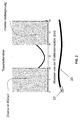
- FIGS 2 and 3 illustrate how an external electromagnetic field can lead to heating of body tissue near the distal end of an electrode lead, such as the electrode lead 20.
- the superposition principle of elementary waves applies along the conductor.
- the amplitude of the decoupling results from the constructive or destructive superposition of the waves at the point of decoupling. Since implantable conductors are a highly attenuated system, the following is the case with respect to the coupling of electromagnetic waves at the end of the electrical conductor: Coupling in the vicinity of both the one and the other end of the electrical conductor causes direct and reflected constructions Waves maxima for decoupling (see FIG. 2 ). Due to the attenuation, these maxima can also be observed with non-resonant conductors.
- one end of the conductor is in contact with the body surface at a greater distance from the body surface (distal end of the conductor or electrode lead) and another end with the active implantable medical device (proximal end of the conductor or electrode lead) near the body surface.
- the amplitude of the incident wave is greatly reduced due to the damping in the body and thus contributes only to the amplitude of the coupling-out at the end of the electrode (see FIG. 3 ).
- the proximal end is near the body surface in the shoulder area, exposing it to a stronger external field.
- FIG. 4 shows the connector housing 104 and the electrical components of a filter feedthrough of a conventional cardiac pacemaker. in contrast to this shows FIG. 5 a schematic representation of an example of a pacemaker with a line extension according to the invention with an electrical component 120 whose electrical length corresponds to at least a quarter of the wavelength ⁇ of electromagnetic waves in the radio frequency range.
- the medical device has an electrically conductive housing 100, which is made of the housing 12 FIG. 1 equivalent. Connected to the housing 100 is an electrode lead 102 having a tip electrode 106. The tip electrode 106 forms an electrode pole. The electrode pole is connected via a feed line 110 to an electronics inside the housing 100. The supply line 110 forms a functional conductor.
- the supply line 110 (function ladder) is via a in FIGS. 4 and 5 not shown plug out.
- FIG. 4 closes at the plug a filter bushing with a connection electronics 120, to which in turn the pacemaker electronics (not shown) is connected inside the housing 100.
- connection electronics 120 is used u.a. the filtering of the signals and is formed for example by two parallel connected series connection of a coil 122 and a capacitor 124, which in turn is followed by a parallel connection of an ohmic resistor 126 and another capacitor 128.
- the connection electronics is arranged in the connection housing 104.
- components 130 for impedance matching are arranged, which are each formed by an ohmic resistor 132 and a capacitor 134 connected in parallel thereto.
- the functional conductor 110 or the functional conductors 110 are connected to the lead extension 140 via the impedance matching component 130, which has two extension conductors 142 arranged in the housing 100 of the cardiac pacemaker and at its proximal end remote from the connector housing 104 with connection electronics 120 '. are connected.
- the connection electronics 120 'in FIG. 5 is essentially the same as FIG. 4 , only it is not in the connection housing 104, but arranged in the housing 100.
- two series circuits the input side each have components 130 for impedance matching, then subsequently each an extension conductor 142, which is completed with a coil (inductance) 122 'and a capacitor (capacitor) 1234'.
- These two series circuits are connected in parallel to each other, that is, the two capacitors 124 'are the output side connected to each other and in turn connected together with a parallel circuit of an ohmic resistor 126' and a capacitor 128 '.
- the electrical component 140 has an electrical length which corresponds to at least a quarter of the wavelength ⁇ of electromagnetic waves in the radio frequency range and which is also referred to here as a line extension.
- the terminal housing (header) is replaced by a simple Plug connection, preferably supplemented by the components 130 for impedance matching to the electrode line to minimize reflections.
- line extension 140 within the pacemaker preferably low-impedance ropes / wires 20cm are guided along the housing 100 and thus extends the electrical length of the function conductor 110 of the electrode line 102 accordingly.
- the extension corresponds approximately to a double winding of the electrode lead around the pacemaker.
- Investigations within an RF resonator have revealed that additional winding of electrode leads around the pacemaker results in a significant reduction in RF-induced heating since the area of the coils is partially shielded by the metallic housing of the pacemaker.
- a capacitive coupling of the cables / wires to the housing of the pacemaker is an additional possibility to deliver coupled energy to the surrounding tissue without damaging the tissue by heat.
Landscapes
- Health & Medical Sciences (AREA)
- Life Sciences & Earth Sciences (AREA)
- Cardiology (AREA)
- Animal Behavior & Ethology (AREA)
- General Health & Medical Sciences (AREA)
- Engineering & Computer Science (AREA)
- Biomedical Technology (AREA)
- Veterinary Medicine (AREA)
- Heart & Thoracic Surgery (AREA)
- Public Health (AREA)
- Radiology & Medical Imaging (AREA)
- Nuclear Medicine, Radiotherapy & Molecular Imaging (AREA)
- Physics & Mathematics (AREA)
- Electromagnetism (AREA)
- Biophysics (AREA)
- Pathology (AREA)
- Medical Informatics (AREA)
- Molecular Biology (AREA)
- Surgery (AREA)
- Electrotherapy Devices (AREA)
- Neurology (AREA)
Abstract
Description
- Die Erfindung betrifft ein permanent oder temporär implantierbares Gerät zur Verwendung mit einem langgestreckten elektrischen Leiter.
- Langgestreckte elektrische Leiter sind beispielsweise in Elektrodenleitungen für die Elektrostimulation enthalten. Diese haben den Nachteil, dass sich ihr elektrischer Leiter in einem Kernspintomografen erwärmen kann, weil die im Kernspintomografen herrschenden wechselnden Magnetfelder in dem elektrischen Leiter nicht unbeachtliche elektrische Ströme induzieren. Auch können solche induzierten Ströme über Elektrodenpole der Elektrodenleitung an umliegendes Gewebe abgegeben werden und so beispielsweise zu unerwünschten Gewebeerwärmungen führen. Deshalb können Herzschrittmacherpatienten heutzutage in der Regel nicht oder nur eingeschränkt in einem Kernspintomografen untersucht werden.
- An implantierbaren Herzschrittmachern oder Defibrillatoren (im Folgenden auch gemeinsam als Herzstimulatoren oder IPG (implantable pulse generator) bezeichnet) sind nämlich typischerweise wenigstens eine Stimulationselektrodenleitung angeschlossen, die an ihrem proximalen, zum Anschluss an den Herzschrittmacher oder Defibrillator vorgesehenen Ende einen standardisierten elektrischen Anschluss aufweist und an ihrem distalen, zur Platzierung im Herzen vorgesehenen Ende einen oder mehrere Elektrodenpole aufweist. Ein solcher Elektrodenpol dient zur Abgabe elektrischer Impulse an das Gewebe (Myokard) des Herzens oder zum Abfühlen elektrischer Felder, um im Rahmen des sogenannten Sensings eine Aktivität eines Herzens abfühlen zu können. Zu diesen Zwecken bilden Elektrodenpole typischerweise elektrisch leitende Oberflächenabschnitte einer Elektrodenleitung. Elektrodenpole sind typischerweise als Ring-Elektrode in Form eines Rings um die Elektrodenleitung oder in Form einer Spitzen- oder Tippelektrode am distalen Ende der Elektrodenleitung vorgesehen. Die Elektrodenpole sind über eine oder mehrere elektrische Leiter mit Kontakten des elektrischen Anschlusses der Elektrodenleitung an deren proximalem Ende elektrisch leitend verbunden. Somit verlaufen zwischen den Kontakten des elektrischen Anschlusses die Elektrodenleitungen an deren proximalen Ende und den Elektrodenpolen am distalen Ende der Elektrodenleitung ein oder mehrere elektrische Leiter, die einen oder mehrere der Elektrodenpole mit einem oder mehreren der Kontakte elektrisch verbinden. Diese elektrischen Leiter können einerseits zur Übertragung von Stimulationsimpulsen zu den Elektrodenpolen und andererseits zur Übertragung mittels der Elektrodenpole aufgenommener elektrischer Signale zum proximalen Ende der Elektrodenleitung genutzt werden und werden im Verlauf der weiteren Beschreibung auch jeweils als Funktionsleiter bezeichnet. Solche Funktionsleiter sind für die Funktionen der jeweiligen Elektrodenleitung erforderliche elektrische Leiter und als solche der Gefahr ausgesetzt, dass in ihnen durch äußere Wechselmagnetfelder elektrische Ströme induziert werden, die beispielsweise zu einer unerwünschten Erwärmung der Funktionsleiter oder der mit ihr verbundenen Elektrodenpole führen können oder die zur Abgabe entsprechender Ströme über die Elektrodenpole an umgebendes Gewebe und damit zu einer Erwärmung des umgebenden Gewebes führen können.
- Der Erfindung liegt die Aufgabe zugrunde, ein Gerät zu schaffen, welches das zuvor beschriebene Problem löst.
- Erfindungsgemäß wird diese Aufgabe durch ein temporär oder permanent implantierbares medizinisches Gerät gelöst, das ein Gehäuse aufweist und mit wenigstens einem langgestreckten elektrischen Funktionsleiter für die Übertragung von Therapiesignalen oder Diagnosesignalen oder beidem verbunden oder zu verbinden ist, und wenigstens einem mit dem Funktionsleiter verbundenen Elektrodenpol, über den elektrischer Strom an im Benutzungsfall anliegendes Körpergewebe abgegeben oder mit dem elektrische Potentiale in im Benutzungsfall umgebenden Gewebe abgefühlt werden können oder beides.
- Erfindungsgemäß weist das medizinische Gerät in dem Gehäuse eine elektrische Komponente als Leitungsverlängerung auf, die mit dem Funktionsleiter verbunden oder zu verbinden ist und die eine elektrische Länge aufweist, die wenigstens ein Viertel der Wellenlänge λ (Lambda) von elektromagnetischen Wellen im Radiofrequenzbereich wie sie in Kernspinntomographen auftreten, beträgt.
- Durch Verwendung einer Verlängerung der Elektrodenleitung innerhalb des Gehäuses des implantierbaren medizinischen Gerätes wird eine Verringerung von unerwünschter RF-induzierter Erwärmung erreicht, ohne dass Veränderungen am Design der Elektrodenleitung notwendig sind. Dadurch, dass der für RF-induzierte Erwärmung empfindliche proximale Anteil der Elektrodenleitung durch das Gehäuse des Schrittmachers abgeschirmt wird, ist die Wirkung unabhängig von der Frequenz der eingestrahlten Welle und ist somit sowohl für 1.5 Tesla wie auch für 3 Tesla MRT wirksam.
- Durch Verlängerung der Zuleitung innerhalb des Gehäuses des aktiven implantierbaren medizinischen Gerätes wird die eingekoppelte Energie am proximalen Ende der Elektrodenleitung so reduziert, dass am Punkt der Auskopplung elektrischer Signale (z. B. Stimulation oder Wahrnehmung) am distalen Ende die Amplitude elektromagnetischer Wellen möglichst gering ist.
- Ein medizinisches Gerät, für das die Erfindung besonders relevant ist, ist ein Herzstimulator mit einer Elektrodenleitung, bei der die Funktionsleiter elektrische Leiter der Elektrodenleitung sind, wobei die Elektrodenleitung Elektrodenpole aufweist, welche über die Funktionsleiter mit dem Wellentransfermodul elektrisch verbunden sind.
- Mittels der erfindungsgemäßen Leitungsverlängerung werden Nachteile bekannter Lösungen wie Bandstoppfilter, Tiefpassfilter, Shunt, Billabong oder Stichleitung vermieden. Solche Nachteile sind unter anderem: Filterelemente werden in den Elektrodenkörper integriert. Bewährte Designkonzepte können nicht mehr verwendet werden, so dass zwangsläufig eine Abweichung vom optimalen Elektrodendesign notwendig wird. Das Design wird bzgl. seiner physiologischen Eigenschaften geschwächt. Die Elektrode wird größer und steifer. Das Risiko von Gewebereizung und Perforation steigt. Darüber hinaus befinden sich Filterelemente im therapeutischen Pfad. Dadurch wird die Langlebigkeit der Konstruktion "gefährdet" oder eingeschränkt. Bandstoppfilter sind frequenzselektiv.
- Gemäß einer Ausführungsvariante des erfindungsgemäßen implantierbaren medizinischen Gerätes kann das Gehäuse, beispielsweise eines an eine Elektrodenleitung angeschlossenen implantierbaren Herzstimulators, leitend ausgebildet sein oder einen Elektrodenpol aufweisen, über den im Benutzungsfall elektrischer Strom an umgebendes Körpergewebe abgegeben oder mit dem elektrische Potentiale in umgebenden Gewebe abgefühlt werden können oder beides.
- Vorzugsweise weist das medizinische Gerät eine Komponente zur Impedanzanpassung zwischen dem Funktionsleiter und der Leitungsverlängerung (d.h. der elektrisch leitenden Komponente mit der elektrischen Länge > λ/4) auf, die ausgebildet ist, ein Vorhandensein starker elektromagnetischer Felder zu erfassen und im Falle des Vorhandenseins ein entsprechendes Ausgangssignal zu generieren, um Dämpfung einzustellen.
- Gemäß einer Ausführungsvariante ist die Komponente zur Impedanzanpassung eine Stichleitung oder weist eine solche auf.
- Gemäß einer Ausführungsvariante weist die Komponente zur Impedanzanpassung zusätzlich oder alternativ einen Balun auf.
- Gemäß einer weiteren Ausführungsvariante weist die Komponente zur Impedanzanpassung zusätzlich oder alternativ eine Kapazität auf.
- Gemäß einer weiteren Ausführungsvariante weist die Komponente zur Impedanzanpassung zusätzlich oder alternativ eine Induktivität auf.
- Die Komponente zur Impedanzanpassung kann zusätzlich oder alternativ auch eine Kombination aus Induktivität und Kapazität sein oder eine solche Kombination aufweisen. Vorzugsweise ist die elektrische Komponente, deren elektrische Länge mindestens ein Viertel der Wellenlänge λ von elektromagnetischen Wellen im Radiofrequenzbereich entspricht - also die Leitungsverlängerung -, entlang ihrer Länge isoliert.
- Zusätzlich oder alternativ kann die elektrische Komponente, deren elektrische Länge mindestens ein Viertel der Wellenlänge λ von elektromagnetischen Wellen im Radiofrequenzbereich entspricht, Kontakt mit einem Medium haben, das ganz oder abschnittsweise aus einem der folgenden Werkstoffe oder einer Kombination der folgenden Werkstoffe besteht: Glas, Bariumtitanat, Polyethylen, Siliziumoxid, Siliziumkarbid, Keramik, Piezowerkstoffe, Aluminiumoxid, Titanoxid, Tantaloxid, Halbleiterwerkstoffe, Kunststoffe mit Beimengungen der oben genannten Werkstoffe.
- Gemäß einer weiteren zusätzlichen oder alternativen Ausführungsvariante weist die elektrische Komponente, deren elektrische Länge mindestens ein Viertel der Wellenlänge λ von elektromagnetischen Wellen im Radiofrequenzbereich entspricht, einen Verlängerungsleiter auf, der als eine der Ausführungen oder einer Kombination: Draht/Band, platinierter Draht/Band, gewendelter Draht/Band, Litze, Seil, gedruckter Leiter, geschnittener Leiter, geätzter Leiter, galvanisch abgeschiedener Leiter, geschlitzte leitfähige Fläche realisiert ist.
- Besonders bevorzugt ist ein batteriebetriebenes elektronisches Implantat mit einem elektrisch leitfähigen Gehäuse oder einem Gehäuse mit mindestens einem Elektrodenpol, elektrischen Funktionsleitern, die Elektrodenpole mit elektrischen Durchführungen des Implantats verbinden, um elektrische Signale von dem jeweiligen Elektrodenpol ins Implantat leiten zu können.
- Die Erfindung soll nun anhand von Ausführungsbeispielen mit Bezug auf die Figuren näher erläutert werden. Die Figuren zeigen Folgendes:
- Fig. 1
- zeigt als implantierbare medizinische Geräte einen implantierbaren Herzstimulator 10 und eine daran angeschlossene implantierbare Elektrodenleitung 20.
- Fig. 2
- illustriert die Superposition elektromagnetischer Wellen in einer Elektrodenleitung.
- Fig.3
- illustriert die Amplituden äußerer Wechselmagnetfelder entlang implantierter Elektrodenleitungen.
- Fig. 4
- zeigt in stark schematisierter Darstellung einen herkömmlichen Herzstimulator mit einer Filterdurchführung.
- Fig. 5
- zeigt in stark schematisierter Darstellung einen erfindungsgemäßen Herzstimulator mit einer Leitungsverlängerung.
-
Figur 1 zeigt ein implantierbares aktives medizinisches Gerät in Form eines implantierbaren Herzstimulators 10. Erfindungsgemäße Details sind inFiguren 4 und5 dargestellt. - Der implantierbare Herzstimulator 10 kann ein Herzschrittmacher oder ein Kardioverter/Defibrillator (ICD) sein. Im dargestellten Ausführungsbeispiel ist der Herzstimulator 10 ein ventrikulärer Herzschrittmacher und Defibrillator. Andere bekannte Herzstimulatoren sind Zweikammerherzschrittmacher zur Stimulation des rechten Atriums und des rechten Ventrikels oder biventrikuläre Herzschrittmacher, die zusätzlich zum rechten Ventrikel auch den linken Ventrikel stimulieren können.
- Derartige Stimulatoren 10 besitzen typischerweise ein Gehäuse 12, das im Regelfall aus Metall besteht und somit elektrisch leitend ist und als großflächiger Elektrodenpol dienen kann. An der Außenseite des Gehäuses 12 ist typischerweise ein Anschlussgehäuse 14 befestigt, das auch als Header bezeichnet wird. Ein derartiger Header weist typischerweise Kontaktbuchsen zur Aufnahme von Steckkontakten auf. Die Kontaktbuchsen besitzen elektrische Kontakte 16, die über entsprechende Leiter mit einer in dem Gehäuse 12 des Herzstimulators 10 angeordnete Elektronik verbunden sind.
- Die Elektrodenleitung 20 stellt im Sinne dieser Erfindung ebenfalls ein implantierbares medizinisches Gerät dar. Am distalen Ende der Elektrodenleitung 20 sind in an sich bekannter Manier Elektrodenpole in Form einer Spitzen- oder Tip-Elektrode 22 und einer in deren Nähe angeordneten Ring-Elektrode 24 angeordnet. Die Elektrodenpole 22 und 24 sind so ausgebildet, dass sie je nach Funktion eines Herzstimulators, an den die Elektrodenleitung 20 angeschlossen ist, zum Abfühlen elektrischer Potenziale des Herzgewebes (Myokards) dienen oder zur Abgabe elektrischer Signale, beispielsweise zur Abgabe von Stimulationsimpulsen an das sie umgebende Herzgewebe, ausgebildet sind.
Figur 1 zeigt, wie sich die Elektrodenpole, also die Tip-Elektrode 22 und die Ring-Elektrode 24, im Anwendungsfall die Elektrodenleitung 20, im Apex eines rechten Ventrikels eines Herzens befinden. - Sowohl die Tip-Elektrode 22 als auch die Ring-Elektrode 24 sind über jeweils wenigstens einen elektrischen Leiter 26 mit einem Steckkontakt 28 am proximalen Ende der Elektrodenleitung 20 elektrisch verbunden. Der Steckkontakt 28 besitzt elektrische Kontakte, die mit den elektrischen Kontakten 16 der Kontaktbuchse im Anschlussgehäuse 14 des implantierbaren Herzstimulators korrespondieren. Die elektrischen Leiter 26 in der Elektrodenleitung 20 können als annähernd gestreckte Seilzugleiter oder als helixförmig gewendelte Leiter ausgebildet sein. Solche Leiter, die funktionale Elektrodenpole mit elektrischen Kontakten des Steckkontaktes am proximalen Ende der Elektrodenleitung 20 elektrisch leitend verbinden werden im Rahmen dieses Textes als Funktionsleiter bezeichnet, da sie beispielsweise der Therapie dienende elektrische Signale von Steckkontakt zum jeweiligen Elektrodenpol übertragen oder abgefühlte elektrische Potentiale repräsentierende Signale vom jeweiligen Elektrodenpol zum Steckkontakt führen und somit der elementaren Funktion des medizinischen Gerätes dienen.
- Die elektrischen Leiter 26, die die Elektrodenpole 22 bzw. 24 mit den elektrischen Kontakten des Steckers 28 der Elektrodenleitung 20 verbinden, sind über den größten Teil ihrer Länge von einer isolierenden Hülle umgeben, so dass ein elektrischer Kontakt zum Gewebe des Herzens gezielt über die Elektrodenpole zustande kommt.
- Neben den Elektrodenpolen 22 und 24, die typischerweise der (in diesem Fall ventrikulären) Stimulation des Herzgewebes dienen, weist die Elektrodenleitung 20 auch noch zwei großflächigere Elektrodenpole 30 und 32 auf, die als Defibrillationselektroden dienen und von wenigstens einem blank liegenden helixartig gewendelten Draht gebildet sind.
- Es sei darauf hingewiesen, dass die Erfindung im Rahmen dieses Ausführungsbeispiels anhand eines rechtsventrikulären Herzschrittmachers und Defibrillators erläutert wird. Als medizinisches Gerät im Sinne der Erfindung kann grundsätzlich aber beispielsweise auch eine Ablationselektrodenleitung dienen, die im Anwendungsfall ebenfalls bis ins Herz eines Patienten hineinragt und die von einem außerhalb des Patienten angeordneten Gerät gesteuert wird und hierzu mit diesem verbunden ist.
-
Figuren 2 und3 illustrieren, wie ein äußeres elektromagnetisches Feld zu einer Erwärmung von Körpergewebe in der Nähe des distalen Endes einer Elektrodenleitung wie der Elektrodenleitung 20 führen kann. - Für die Einkopplung elektromagnetischer Wellen in langgestreckten elektrischen Leitern wie dem Leiter 26 der Elektrodenleitung 20 gilt das Superpositionsprinzip von Elementarwellen entlang des Leiters. Die Amplitude der Auskopplung ergibt sich aus der konstruktiven bzw. destruktiven Superposition der Wellen am Ort der Auskopplung. Da es sich bei implantierbaren Leitern um ein stark gedämpftes System handelt, ergibt sich bezüglich der Einkopplung elektromagnetischer Wellen am Ende des elektrischen Leiters folgendes: Eine Einkopplung in der Nähe sowohl des einen als auch des anderen Endes des elektrischen Leiters bewirkt durch konstruktive Überlagerung direkter und reflektierter Wellen Maxima für die Auskopplung (siehe
Figur 2 ). Diese Maxima sind wegen der Dämpfung auch bei nicht resonanten Leitern zu beobachten. Betrachtet man die Lage der Enden nach Implantation eines langgestreckten Leiters und eines aktiven implantierbaren medizinischen Gerätes, so befindet sich ein Ende des Leiters innerhalb des Körpers mit einem größeren Abstand zur Körperoberfläche (distales Ende des Leiters bzw. der Elektrodenleitung) und ein anderes Ende in Kontakt mit dem aktiven implantierbaren medizinischen Gerät (proximales Ende des Leiters bzw. der Elektrodenleitung) in der Nähe der Körperoberfläche. - Im Bereich des distalen Endes ist die Amplitude der eingestrahlten Welle aufgrund der Dämpfung im Körper stark verringert und trägt damit nur reduziert zur Amplitude der Auskopplung am Elektrodenende bei (siehe
Figur 3 ). - Das proximale Ende hingegen befindet sich nahe der Körperoberfläche im Schulterbereich und ist damit einem stärkeren externen Feld ausgesetzt.
-
Figur 4 zeigt das Anschlussgehäuse 104 und die elektrischen Komponenten einer Filterdurchführung eines herkömmlichen Herzschrittmachers. im Unterschied hierzu zeigtFigur 5 in schematischer Darstellung ein Beispiel eines Herzschrittmachers mit einer erfindungsgemäßen Leitungsverlängerung mit einer elektrischen Komponente 120, deren elektrische Länge mindestens ein Viertel der Wellenlänge λ von elektromagnetischen Wellen im Radiofrequenzbereich entspricht. - Das medizinische Gerät besitzt ein elektrisch leitendes Gehäuse 100, das dem Gehäuse 12 aus
Figur 1 entspricht. An das Gehäuse 100 angeschlossen ist eine Elektrodenleitung 102, die eine Tip-Elektrode 106 aufweist. Die Tip-Elektrode 106 bildet einen Elektrodenpol. Der Elektrodenpol ist über eine Zuleitung 110 mit einer Elektronik im Inneren des Gehäuses 100 verbunden. Die Zuleitung 110 bildet einen Funktionsleiter. - Die Zuleitung 110 (Funktionsleiter) ist über einen in
Figuren 4 und5 nicht dargestellten Stecker geführt. - Bei dem Stand der Technik gemäß
Figur 4 schließt sich an den Stecker eine Filterdurchführung mit einer Anschlusselektronik 120 an, an die wiederum die Herzschrittmacherelektronik (nicht dargestellt) im Inneren des Gehäuses 100 angeschlossen ist. - Die Anschlusselektronik 120 dient u.a. der Filterung der Signale und wird beispielsweise von zwei einander parallel geschalteten Serienschaltung einer Spule 122 und eines Kondensators 124 gebildet, an die sich wiederum eine Parallelschaltung eines ohmschen Widerstands 126 und eines weiteren Kondensators 128 anschließt. Die Anschlusselektronik ist in dem Anschlussgehäuse 104 angeordnet.
- Gemäß dem Ausführungsbeispiel in
Figur 5 sind in dem Anschlussgehäuse 104 Komponenten 130 zur Impedanzanpassung angeordnet, die jeweils von einem Ohmschen Widerstand 132 und einem dazu parallel geschalteten Kondensator 134 gebildet sind. Der Funktionsleiter 110 oder die Funktionsleiter 110 sind über die Komponente 130 zur Impedanzanpassung mit der Leitungsverlängerung 140 verbunden, die zwei Verlängerungsleiter 142 aufweist, die in dem Gehäuse 100 des Herzschrittmachers angeordnet sind und an ihrem proximalen, vom Anschlussgehäuse 104 entfernten Ende mit einer Anschlusselektronik 120' verbunden sind. Die Anschlusselektronik 120' inFigur 5 entspricht im Wesentlichen derjenigen ausFigur 4 , nur ist sie nicht im Anschlussgehäuse 104, sondern im Gehäuse 100 angeordnet. - Auf diese Weise ergeben sich zwei Serienschaltungen, die eingangsseitig jeweils Komponenten 130 zur Impedanzanpassung aufweisen, daran anschließend jeweils einen Verlängerungsleiter 142, der mit einer Spule (Induktivität) 122' und einem Kondensator (Kapazität) 1234' abgeschlossen ist. Diese beiden Serienschaltungen sind einander parallel geschaltet, das heißt die beiden Kondensatoren 124' sind ausgangsseitig miteinander verbunden und ihrerseits wieder gemeinsam mit einer Parallelschaltung aus einem Ohmschen Widerstand 126' und einem Kondensator 128' verbunden.
- Die elektrische Komponente 140 hat eine elektrische Länge, die mindestens ein Viertel der Wellenlänge λ von elektromagnetischen Wellen im Radiofrequenzbereich entspricht und die hier auch als Leitungsverlängerung bezeichnet wird.
- Gegenüber einem herkömmlichen Herzschrittmacher wird bei dem erfindungsgemäßen Herzschrittmacher das Anschlussgehäuse (Header) ausgetauscht durch eine einfache Steckverbindung, vorzugsweise ergänzt durch die Komponenten 130 zur Impedanzanpassung an die Elektrodenleitung um Reflexionen zu minimieren.
- Als Leitungsverlängerung 140 innerhalb des Schrittmachers werden (vorzugsweise niederohmige) Seile/Drähte 20cm entlang des Gehäuses 100 geführt und somit die elektrische Länge des Funktionsleiters 110 der Elektrodenleitung 102 entsprechend verlängert. Die Verlängerung entspricht in etwa einer zweifachen Wicklung der Elektrodenleitung um den Herzschrittmacher. Untersuchungen innerhalb eines RF-Resonators haben ergeben, dass zusätzliche Wicklungen von Elektrodenleitungen um den Herzschrittmacher zu einer deutlichen Reduzierung RF-induzierter Erwärmung führt, da der Bereich der Wicklungen teilweise durch das metallische Gehäuse des Herzschrittmachers abgeschirmt wird. Die eigentliche Anschlussstelle der Elektrodenleitung an die Funktionen des aktiven implantierbaren medizinisches Gerätes - hier: des Herzschrittmachers - befindet sich innerhalb des Gehäuses des Herzschrittmachers. Eine kapazitive Kopplung der Seile/Drähte an das Gehäuse des Herzschrittmachers ist eine zusätzliche Möglichkeit, eingekoppelte Energie an das umgebende Gewebe abzugeben ohne das Gewebe durch Wärmeeinwirkung zu schädigen.
-
- 10
- Herzstimulator
- 12, 100
- Gehäuse
- 14, 104
- Anschlussgehäuse
- 16
- elektrischer Kontakt
- 20, 102
- Elektrodenleitung
- 22, 106
- Tip-Elektrode
- 24
- Ring-Elektrode
- 26
- elektrischer Leiter
- 28
- Steckkontakt
- 30,32
- Elektrodenpol
- 110
- Zuleitung
- 120, 120'
- Anschlusselektronik
- 122, 122'
- Spule (Induktivität)
- 124, 124'
- Kondensator (Kapazität)
- 126, 126'
- Ohmscher Widerstand
- 128, 128'
- weiterer Kondensator
- 130
- Komponenten zur Impedanzanpassung
- 132
- Ohmscher Widerstand
- 134
- Kondensator
- 140
- Leitungsverlängerung
- 142
- Verlängerungsleiter
Claims (12)
- Temporär oder permanent implantierbares medizinisches Gerät, das ein Gehäuse (12, 100) umfasst und das mit wenigstens einem langgestreckten elektrischen Funktionsleiter für die Übertragung von Therapiesignalen oder Diagnosesignalen oder beidem verbunden oder zu verbinden ist, und wenigstens einem mit dem Funktionsleiter verbundenen Elektrodenpol (30, 32), über den elektrischer Strom an im Benutzungsfall umgebendes Körpergewebe abgegeben oder mit dem elektrische Potentiale in im Benutzungsfall umgebenden Gewebe abgefühlt werden können oder beides
dadurch gekennzeichnet, dass das medizinische Gerät mindestens eine elektrische Komponente aufweist, die sich innerhalb des Gehäuses (12, 100) befindet und deren elektrische Länge mindestens ein Viertel der Wellenlänge λ von elektromagnetischen Wellen im Radiofrequenzbereich entspricht. - Medizinisches Gerät nach Anspruch 1, dadurch gekennzeichnet dass der Funktionsleiter ein elektrischer Leiter (26) einer Elektrodenleitung (20, 102) ist, die wenigstens einen Elektrodenpol (30; 32) aufweist, welcher über den Funktionsleiter mit der innerhalb des Gehäuses (12, 100) angeordneten elektrischen Komponente, deren elektrische Länge mindestens ein Viertel der Wellenlänge λ von elektromagnetischen Wellen im Radiofrequenzbereich entspricht, elektrisch verbunden ist.
- Medizinisches Gerät nach Anspruch 1 oder 2, dadurch gekennzeichnet, dass das medizinische Gerät ein Gehäuse (12, 100) besitzt, welches elektrisch leitend ausgebildet ist oder einen Elektrodenpol (30, 32) aufweist, über den im Benutzungsfall elektrischer Strom an umgebendes Körpergewebe abgegeben oder mit dem elektrische Potentiale in umgebenden Gewebe abgefühlt werden können oder beides.
- Medizinisches Gerät nach wenigstens einem der Ansprüche 1 bis 3, dadurch gekennzeichnet, dass das medizinische Gerät eine Komponente (130) zur Impedanzanpassung zwischen dem Funktionsleiter (110) und der elektrisch leitenden Komponente (140) mit der elektrischen Länge > λ/4 aufweist, die ausgebildet ist, die Impedanzen des Funktionsleiters (110) und der elektrisch leitenden Komponente (140) mit der elektrischen Länge > λ/4 aneinander anzupassen.
- Medizinisches Gerät nach Anspruch 4, dadurch gekennzeichnet, dass die Komponente zur Impedanzanpassung (130) eine Stichleitung ist oder eine solche aufweist.
- Medizinisches Gerät nach Anspruch 4 oder 5, dadurch gekennzeichnet, dass die Komponente zur Impedanzanpassung (130) ein Balun ist oder einen solchen aufweist.
- Medizinisches Gerät nach wenigstens einem der Ansprüche 4 bis 6, dadurch gekennzeichnet, dass die Komponente (130) zur Impedanzanpassung eine Kapazität (134) ist oder eine solche aufweist.
- Medizinisches Gerät nach wenigstens einem der Ansprüche 4 bis 7, dadurch gekennzeichnet, dass die Komponente (130) zur Impedanzanpassung eine Induktivität ist oder eine solche aufweist.
- Medizinisches Gerät nach wenigstens einem der Ansprüche 4 bis 8, dadurch gekennzeichnet, dass die Komponente zur Impedanzanpassung (130) eine Kombination aus Induktivität und Kapazität ist oder eine solche Kombination aufweist.
- Medizinisches Gerät nach wenigstens einem der Ansprüche 1 bis 9, dadurch gekennzeichnet, dass die elektrische Komponente (140), deren elektrische Länge mindestens ein Viertel der Wellenlänge λ von elektromagnetischen Wellen im Radiofrequenzbereich entspricht, entlang ihrer Länge isoliert ist.
- Medizinisches Gerät nach wenigstens einem der Ansprüche 1 bis 10, dadurch gekennzeichnet, dass die elektrische Komponente, (140) deren elektrische Länge mindestens ein Viertel der Wellenlänge λ von elektromagnetischen Wellen im Radiofrequenzbereich entspricht, Kontakt mit einem Medium hat, das ganz oder abschnittsweise aus einem der folgenden Werkstoffe oder einer Kombination der folgenden Werkstoffe besteht: Glas, Bariumtitanat, Polyethylen, Siliziumoxid, Siliziumkarbid, Keramik, Piezowerkstoffe, Aluminiumoxid, Titanoxid, Tantaloxid, Halbleiterwerkstoffe, Kunststoffe mit Beimengungen der oben genannten Werkstoffe.
- Medizinisches Gerät nach wenigstens einem der Ansprüche 1 bis 11, dadurch gekennzeichnet, dass die elektrische Komponente (140), deren elektrische Länge mindestens ein Viertel der Wellenlänge λ von elektromagnetischen Wellen im Radiofrequenzbereich entspricht, einen Verlängerungsleiter (142) aufweist, der als eine der Ausführungen oder einer Kombination: Draht/Band, platinierter Draht/Band, gewendelter Draht/Band, Litze, Seil, gedruckter Leiter, geschnittener Leiter, geätzter Leiter, galvanisch abgeschiedener Leiter, geschlitzte leitfähige Fläche realisiert ist.
Applications Claiming Priority (1)
| Application Number | Priority Date | Filing Date | Title |
|---|---|---|---|
| US201462085249P | 2014-11-27 | 2014-11-27 |
Publications (3)
| Publication Number | Publication Date |
|---|---|
| EP3025756A2 true EP3025756A2 (de) | 2016-06-01 |
| EP3025756A3 EP3025756A3 (de) | 2016-08-24 |
| EP3025756B1 EP3025756B1 (de) | 2019-01-09 |
Family
ID=54337184
Family Applications (1)
| Application Number | Title | Priority Date | Filing Date |
|---|---|---|---|
| EP15190500.7A Not-in-force EP3025756B1 (de) | 2014-11-27 | 2015-10-20 | Im aktiven implantat integrierte elektrodenverlängerung |
Country Status (2)
| Country | Link |
|---|---|
| US (1) | US10617865B2 (de) |
| EP (1) | EP3025756B1 (de) |
Family Cites Families (11)
| Publication number | Priority date | Publication date | Assignee | Title |
|---|---|---|---|---|
| US20030144718A1 (en) * | 2002-01-29 | 2003-07-31 | Zeijlemaker Volkert A. | Method and apparatus for shielding coating for MRI resistant electrode systems |
| US6793823B2 (en) * | 2002-08-07 | 2004-09-21 | Aqua-Aerobics Systems, Inc. | Wastewater solids removal methods |
| US7392091B2 (en) * | 2003-12-30 | 2008-06-24 | Cochlear Limited | Implanted antenna and radio communications link |
| US9468750B2 (en) * | 2006-11-09 | 2016-10-18 | Greatbatch Ltd. | Multilayer planar spiral inductor filter for medical therapeutic or diagnostic applications |
| EP2269200B1 (de) * | 2008-03-20 | 2014-09-24 | Greatbatch Ltd. | Abgeschirmtes flachdurchgangs-emi/energieableitungsfilter mit drei anschlüssen |
| WO2010078552A1 (en) * | 2009-01-05 | 2010-07-08 | Kenergy, Inc. | Mri compatible electrical lead for an implantable electronic medical device |
| US9399131B2 (en) * | 2009-06-30 | 2016-07-26 | Boston Scientific Neuromodulation Corporation | Moldable charger with support members for charging an implantable pulse generator |
| US8321017B2 (en) * | 2009-07-08 | 2012-11-27 | Pacesetter, Inc. | Electromechanical delay (EMD) monitoring devices, systems and methods |
| US9204842B2 (en) * | 2010-10-29 | 2015-12-08 | Medtronic, Inc. | Medical device fixation attachment mechanism |
| WO2012057873A1 (en) * | 2010-10-29 | 2012-05-03 | Medtronic. Inc. | Protecting an implantable medical device from effects caused by an interfering radiation field |
| US8478223B2 (en) * | 2011-01-03 | 2013-07-02 | Valentine Research, Inc. | Methods and apparatus for receiving radio frequency signals |
-
2015
- 2015-10-20 EP EP15190500.7A patent/EP3025756B1/de not_active Not-in-force
- 2015-11-19 US US14/946,617 patent/US10617865B2/en not_active Expired - Fee Related
Non-Patent Citations (1)
| Title |
|---|
| None |
Also Published As
| Publication number | Publication date |
|---|---|
| US20160151625A1 (en) | 2016-06-02 |
| EP3025756A3 (de) | 2016-08-24 |
| EP3025756B1 (de) | 2019-01-09 |
| US10617865B2 (en) | 2020-04-14 |
Similar Documents
| Publication | Publication Date | Title |
|---|---|---|
| EP1923094B1 (de) | Elektrodenkatheter zu Interventionszwecken | |
| US8483840B2 (en) | Dual function tuned L-C input trap passive EMI filter component network for an active implantable medical device | |
| EP2773422B1 (de) | Leitung für eine implantierbare medizinische vorrichtung mit einer im verhältnis zu einer defibrillationsspule umgekehrt gewickelten innenspule | |
| EP2465572B1 (de) | MRT-kompatible implantierbare Leitung | |
| EP2502646B1 (de) | Implantierbares Gerät | |
| EP2578268B1 (de) | Temperatursensor für ein implantierbares medizinisches Gerät | |
| EP2359895B1 (de) | Adaptionssonde zur Einführung in implantierte Elektrodenvorrichtungen aktiver medizinischer Implantate sowie Set bestehend aus einer implantierbaren Elektrodenvorrichtung und einer Adaptionssonde | |
| EP2468353B1 (de) | Implantierbares Gerät | |
| EP2465569B1 (de) | Implantierbares Gerät | |
| EP2985053A1 (de) | Implantierbare elektrische leitung | |
| EP2446922B1 (de) | Implantierbare Leiter mit zusätzlichen Leitern zur Feldentkopplung | |
| EP2478932B1 (de) | Implantierbares Gerät | |
| EP2848282B1 (de) | Implantierbares Gerät | |
| EP3025756B1 (de) | Im aktiven implantat integrierte elektrodenverlängerung | |
| EP2465573B1 (de) | Implantierbares Gerät | |
| EP2465570B1 (de) | Implantierbares Gerät | |
| EP2478933A2 (de) | Implantierbares Gerät | |
| EP2985054B1 (de) | Implantierbares gerät mit elektrischem filter | |
| EP2468356B1 (de) | Implantierbares Gerät | |
| US20130116765A1 (en) | Implantable lead adaptor with mri filter | |
| EP2465571B1 (de) | Implantierbares Gerät | |
| EP2505229A2 (de) | Implantierbares Gerät | |
| EP2848281B1 (de) | Elektrodenvorrichtung für ein medizinisches Implantat und medizinisches Implantat mit einer Elektrodenvorrichtung | |
| EP3009165A1 (de) | Implantierbare elektrische leitung | |
| EP2529785A1 (de) | Vorrichtung für medizinische Anwendungen und elektromedizinisches Implantat |
Legal Events
| Date | Code | Title | Description |
|---|---|---|---|
| PUAI | Public reference made under article 153(3) epc to a published international application that has entered the european phase |
Free format text: ORIGINAL CODE: 0009012 |
|
| AK | Designated contracting states |
Kind code of ref document: A2 Designated state(s): AL AT BE BG CH CY CZ DE DK EE ES FI FR GB GR HR HU IE IS IT LI LT LU LV MC MK MT NL NO PL PT RO RS SE SI SK SM TR |
|
| AX | Request for extension of the european patent |
Extension state: BA ME |
|
| PUAL | Search report despatched |
Free format text: ORIGINAL CODE: 0009013 |
|
| AK | Designated contracting states |
Kind code of ref document: A3 Designated state(s): AL AT BE BG CH CY CZ DE DK EE ES FI FR GB GR HR HU IE IS IT LI LT LU LV MC MK MT NL NO PL PT RO RS SE SI SK SM TR |
|
| AX | Request for extension of the european patent |
Extension state: BA ME |
|
| RIC1 | Information provided on ipc code assigned before grant |
Ipc: A61N 1/08 20060101ALI20160720BHEP Ipc: A61N 1/375 20060101ALN20160720BHEP Ipc: A61N 1/37 20060101AFI20160720BHEP |
|
| STAA | Information on the status of an ep patent application or granted ep patent |
Free format text: STATUS: REQUEST FOR EXAMINATION WAS MADE |
|
| 17P | Request for examination filed |
Effective date: 20170213 |
|
| RBV | Designated contracting states (corrected) |
Designated state(s): AL AT BE BG CH CY CZ DE DK EE ES FI FR GB GR HR HU IE IS IT LI LT LU LV MC MK MT NL NO PL PT RO RS SE SI SK SM TR |
|
| GRAP | Despatch of communication of intention to grant a patent |
Free format text: ORIGINAL CODE: EPIDOSNIGR1 |
|
| STAA | Information on the status of an ep patent application or granted ep patent |
Free format text: STATUS: GRANT OF PATENT IS INTENDED |
|
| RIC1 | Information provided on ipc code assigned before grant |
Ipc: A61N 1/08 20060101ALI20180831BHEP Ipc: A61N 1/375 20060101ALN20180831BHEP Ipc: A61N 1/37 20060101AFI20180831BHEP |
|
| INTG | Intention to grant announced |
Effective date: 20180928 |
|
| GRAS | Grant fee paid |
Free format text: ORIGINAL CODE: EPIDOSNIGR3 |
|
| GRAA | (expected) grant |
Free format text: ORIGINAL CODE: 0009210 |
|
| STAA | Information on the status of an ep patent application or granted ep patent |
Free format text: STATUS: THE PATENT HAS BEEN GRANTED |
|
| AK | Designated contracting states |
Kind code of ref document: B1 Designated state(s): AL AT BE BG CH CY CZ DE DK EE ES FI FR GB GR HR HU IE IS IT LI LT LU LV MC MK MT NL NO PL PT RO RS SE SI SK SM TR |
|
| REG | Reference to a national code |
Ref country code: GB Ref legal event code: FG4D Free format text: NOT ENGLISH |
|
| REG | Reference to a national code |
Ref country code: CH Ref legal event code: EP Ref country code: AT Ref legal event code: REF Ref document number: 1086571 Country of ref document: AT Kind code of ref document: T Effective date: 20190115 |
|
| REG | Reference to a national code |
Ref country code: DE Ref legal event code: R096 Ref document number: 502015007584 Country of ref document: DE |
|
| REG | Reference to a national code |
Ref country code: IE Ref legal event code: FG4D Free format text: LANGUAGE OF EP DOCUMENT: GERMAN |
|
| REG | Reference to a national code |
Ref country code: NL Ref legal event code: MP Effective date: 20190109 |
|
| REG | Reference to a national code |
Ref country code: LT Ref legal event code: MG4D |
|
| PG25 | Lapsed in a contracting state [announced via postgrant information from national office to epo] |
Ref country code: NL Free format text: LAPSE BECAUSE OF FAILURE TO SUBMIT A TRANSLATION OF THE DESCRIPTION OR TO PAY THE FEE WITHIN THE PRESCRIBED TIME-LIMIT Effective date: 20190109 |
|
| PG25 | Lapsed in a contracting state [announced via postgrant information from national office to epo] |
Ref country code: NO Free format text: LAPSE BECAUSE OF FAILURE TO SUBMIT A TRANSLATION OF THE DESCRIPTION OR TO PAY THE FEE WITHIN THE PRESCRIBED TIME-LIMIT Effective date: 20190409 Ref country code: FI Free format text: LAPSE BECAUSE OF FAILURE TO SUBMIT A TRANSLATION OF THE DESCRIPTION OR TO PAY THE FEE WITHIN THE PRESCRIBED TIME-LIMIT Effective date: 20190109 Ref country code: LT Free format text: LAPSE BECAUSE OF FAILURE TO SUBMIT A TRANSLATION OF THE DESCRIPTION OR TO PAY THE FEE WITHIN THE PRESCRIBED TIME-LIMIT Effective date: 20190109 Ref country code: PL Free format text: LAPSE BECAUSE OF FAILURE TO SUBMIT A TRANSLATION OF THE DESCRIPTION OR TO PAY THE FEE WITHIN THE PRESCRIBED TIME-LIMIT Effective date: 20190109 Ref country code: SE Free format text: LAPSE BECAUSE OF FAILURE TO SUBMIT A TRANSLATION OF THE DESCRIPTION OR TO PAY THE FEE WITHIN THE PRESCRIBED TIME-LIMIT Effective date: 20190109 Ref country code: PT Free format text: LAPSE BECAUSE OF FAILURE TO SUBMIT A TRANSLATION OF THE DESCRIPTION OR TO PAY THE FEE WITHIN THE PRESCRIBED TIME-LIMIT Effective date: 20190509 Ref country code: ES Free format text: LAPSE BECAUSE OF FAILURE TO SUBMIT A TRANSLATION OF THE DESCRIPTION OR TO PAY THE FEE WITHIN THE PRESCRIBED TIME-LIMIT Effective date: 20190109 |
|
| PG25 | Lapsed in a contracting state [announced via postgrant information from national office to epo] |
Ref country code: RS Free format text: LAPSE BECAUSE OF FAILURE TO SUBMIT A TRANSLATION OF THE DESCRIPTION OR TO PAY THE FEE WITHIN THE PRESCRIBED TIME-LIMIT Effective date: 20190109 Ref country code: LV Free format text: LAPSE BECAUSE OF FAILURE TO SUBMIT A TRANSLATION OF THE DESCRIPTION OR TO PAY THE FEE WITHIN THE PRESCRIBED TIME-LIMIT Effective date: 20190109 Ref country code: BG Free format text: LAPSE BECAUSE OF FAILURE TO SUBMIT A TRANSLATION OF THE DESCRIPTION OR TO PAY THE FEE WITHIN THE PRESCRIBED TIME-LIMIT Effective date: 20190409 Ref country code: GR Free format text: LAPSE BECAUSE OF FAILURE TO SUBMIT A TRANSLATION OF THE DESCRIPTION OR TO PAY THE FEE WITHIN THE PRESCRIBED TIME-LIMIT Effective date: 20190410 Ref country code: IS Free format text: LAPSE BECAUSE OF FAILURE TO SUBMIT A TRANSLATION OF THE DESCRIPTION OR TO PAY THE FEE WITHIN THE PRESCRIBED TIME-LIMIT Effective date: 20190509 Ref country code: HR Free format text: LAPSE BECAUSE OF FAILURE TO SUBMIT A TRANSLATION OF THE DESCRIPTION OR TO PAY THE FEE WITHIN THE PRESCRIBED TIME-LIMIT Effective date: 20190109 |
|
| REG | Reference to a national code |
Ref country code: DE Ref legal event code: R097 Ref document number: 502015007584 Country of ref document: DE |
|
| PG25 | Lapsed in a contracting state [announced via postgrant information from national office to epo] |
Ref country code: DK Free format text: LAPSE BECAUSE OF FAILURE TO SUBMIT A TRANSLATION OF THE DESCRIPTION OR TO PAY THE FEE WITHIN THE PRESCRIBED TIME-LIMIT Effective date: 20190109 Ref country code: EE Free format text: LAPSE BECAUSE OF FAILURE TO SUBMIT A TRANSLATION OF THE DESCRIPTION OR TO PAY THE FEE WITHIN THE PRESCRIBED TIME-LIMIT Effective date: 20190109 Ref country code: SK Free format text: LAPSE BECAUSE OF FAILURE TO SUBMIT A TRANSLATION OF THE DESCRIPTION OR TO PAY THE FEE WITHIN THE PRESCRIBED TIME-LIMIT Effective date: 20190109 Ref country code: AL Free format text: LAPSE BECAUSE OF FAILURE TO SUBMIT A TRANSLATION OF THE DESCRIPTION OR TO PAY THE FEE WITHIN THE PRESCRIBED TIME-LIMIT Effective date: 20190109 Ref country code: IT Free format text: LAPSE BECAUSE OF FAILURE TO SUBMIT A TRANSLATION OF THE DESCRIPTION OR TO PAY THE FEE WITHIN THE PRESCRIBED TIME-LIMIT Effective date: 20190109 Ref country code: RO Free format text: LAPSE BECAUSE OF FAILURE TO SUBMIT A TRANSLATION OF THE DESCRIPTION OR TO PAY THE FEE WITHIN THE PRESCRIBED TIME-LIMIT Effective date: 20190109 Ref country code: CZ Free format text: LAPSE BECAUSE OF FAILURE TO SUBMIT A TRANSLATION OF THE DESCRIPTION OR TO PAY THE FEE WITHIN THE PRESCRIBED TIME-LIMIT Effective date: 20190109 |
|
| PLBE | No opposition filed within time limit |
Free format text: ORIGINAL CODE: 0009261 |
|
| STAA | Information on the status of an ep patent application or granted ep patent |
Free format text: STATUS: NO OPPOSITION FILED WITHIN TIME LIMIT |
|
| PG25 | Lapsed in a contracting state [announced via postgrant information from national office to epo] |
Ref country code: SM Free format text: LAPSE BECAUSE OF FAILURE TO SUBMIT A TRANSLATION OF THE DESCRIPTION OR TO PAY THE FEE WITHIN THE PRESCRIBED TIME-LIMIT Effective date: 20190109 |
|
| 26N | No opposition filed |
Effective date: 20191010 |
|
| PG25 | Lapsed in a contracting state [announced via postgrant information from national office to epo] |
Ref country code: SI Free format text: LAPSE BECAUSE OF FAILURE TO SUBMIT A TRANSLATION OF THE DESCRIPTION OR TO PAY THE FEE WITHIN THE PRESCRIBED TIME-LIMIT Effective date: 20190109 |
|
| PG25 | Lapsed in a contracting state [announced via postgrant information from national office to epo] |
Ref country code: TR Free format text: LAPSE BECAUSE OF FAILURE TO SUBMIT A TRANSLATION OF THE DESCRIPTION OR TO PAY THE FEE WITHIN THE PRESCRIBED TIME-LIMIT Effective date: 20190109 |
|
| PG25 | Lapsed in a contracting state [announced via postgrant information from national office to epo] |
Ref country code: MC Free format text: LAPSE BECAUSE OF FAILURE TO SUBMIT A TRANSLATION OF THE DESCRIPTION OR TO PAY THE FEE WITHIN THE PRESCRIBED TIME-LIMIT Effective date: 20190109 |
|
| PG25 | Lapsed in a contracting state [announced via postgrant information from national office to epo] |
Ref country code: LU Free format text: LAPSE BECAUSE OF NON-PAYMENT OF DUE FEES Effective date: 20191020 |
|
| REG | Reference to a national code |
Ref country code: BE Ref legal event code: MM Effective date: 20191031 |
|
| PG25 | Lapsed in a contracting state [announced via postgrant information from national office to epo] |
Ref country code: BE Free format text: LAPSE BECAUSE OF NON-PAYMENT OF DUE FEES Effective date: 20191031 |
|
| GBPC | Gb: european patent ceased through non-payment of renewal fee |
Effective date: 20191020 |
|
| PG25 | Lapsed in a contracting state [announced via postgrant information from national office to epo] |
Ref country code: FR Free format text: LAPSE BECAUSE OF NON-PAYMENT OF DUE FEES Effective date: 20191031 Ref country code: GB Free format text: LAPSE BECAUSE OF NON-PAYMENT OF DUE FEES Effective date: 20191020 |
|
| PG25 | Lapsed in a contracting state [announced via postgrant information from national office to epo] |
Ref country code: CY Free format text: LAPSE BECAUSE OF FAILURE TO SUBMIT A TRANSLATION OF THE DESCRIPTION OR TO PAY THE FEE WITHIN THE PRESCRIBED TIME-LIMIT Effective date: 20190109 |
|
| PG25 | Lapsed in a contracting state [announced via postgrant information from national office to epo] |
Ref country code: MT Free format text: LAPSE BECAUSE OF FAILURE TO SUBMIT A TRANSLATION OF THE DESCRIPTION OR TO PAY THE FEE WITHIN THE PRESCRIBED TIME-LIMIT Effective date: 20190109 Ref country code: HU Free format text: LAPSE BECAUSE OF FAILURE TO SUBMIT A TRANSLATION OF THE DESCRIPTION OR TO PAY THE FEE WITHIN THE PRESCRIBED TIME-LIMIT; INVALID AB INITIO Effective date: 20151020 |
|
| REG | Reference to a national code |
Ref country code: AT Ref legal event code: MM01 Ref document number: 1086571 Country of ref document: AT Kind code of ref document: T Effective date: 20201020 |
|
| PG25 | Lapsed in a contracting state [announced via postgrant information from national office to epo] |
Ref country code: AT Free format text: LAPSE BECAUSE OF NON-PAYMENT OF DUE FEES Effective date: 20201020 |
|
| PGFP | Annual fee paid to national office [announced via postgrant information from national office to epo] |
Ref country code: IE Payment date: 20211021 Year of fee payment: 7 Ref country code: DE Payment date: 20211022 Year of fee payment: 7 |
|
| PGFP | Annual fee paid to national office [announced via postgrant information from national office to epo] |
Ref country code: CH Payment date: 20211022 Year of fee payment: 7 |
|
| PG25 | Lapsed in a contracting state [announced via postgrant information from national office to epo] |
Ref country code: MK Free format text: LAPSE BECAUSE OF FAILURE TO SUBMIT A TRANSLATION OF THE DESCRIPTION OR TO PAY THE FEE WITHIN THE PRESCRIBED TIME-LIMIT Effective date: 20190109 |
|
| REG | Reference to a national code |
Ref country code: DE Ref legal event code: R119 Ref document number: 502015007584 Country of ref document: DE |
|
| REG | Reference to a national code |
Ref country code: CH Ref legal event code: PL |
|
| PG25 | Lapsed in a contracting state [announced via postgrant information from national office to epo] |
Ref country code: LI Free format text: LAPSE BECAUSE OF NON-PAYMENT OF DUE FEES Effective date: 20221031 Ref country code: DE Free format text: LAPSE BECAUSE OF NON-PAYMENT OF DUE FEES Effective date: 20230503 Ref country code: CH Free format text: LAPSE BECAUSE OF NON-PAYMENT OF DUE FEES Effective date: 20221031 |
|
| PG25 | Lapsed in a contracting state [announced via postgrant information from national office to epo] |
Ref country code: IE Free format text: LAPSE BECAUSE OF NON-PAYMENT OF DUE FEES Effective date: 20221020 |