EP3025602A2 - Atomizer and electronic cigarette having same - Google Patents
Atomizer and electronic cigarette having same Download PDFInfo
- Publication number
- EP3025602A2 EP3025602A2 EP16160048.1A EP16160048A EP3025602A2 EP 3025602 A2 EP3025602 A2 EP 3025602A2 EP 16160048 A EP16160048 A EP 16160048A EP 3025602 A2 EP3025602 A2 EP 3025602A2
- Authority
- EP
- European Patent Office
- Prior art keywords
- liquid
- atomizer
- sealing element
- atomizing assembly
- liquid outlet
- Prior art date
- Legal status (The legal status is an assumption and is not a legal conclusion. Google has not performed a legal analysis and makes no representation as to the accuracy of the status listed.)
- Granted
Links
Images




Classifications
-
- A—HUMAN NECESSITIES
- A24—TOBACCO; CIGARS; CIGARETTES; SIMULATED SMOKING DEVICES; SMOKERS' REQUISITES
- A24F—SMOKERS' REQUISITES; MATCH BOXES; SIMULATED SMOKING DEVICES
- A24F40/00—Electrically operated smoking devices; Component parts thereof; Manufacture thereof; Maintenance or testing thereof; Charging means specially adapted therefor
- A24F40/40—Constructional details, e.g. connection of cartridges and battery parts
- A24F40/42—Cartridges or containers for inhalable precursors
-
- H—ELECTRICITY
- H05—ELECTRIC TECHNIQUES NOT OTHERWISE PROVIDED FOR
- H05B—ELECTRIC HEATING; ELECTRIC LIGHT SOURCES NOT OTHERWISE PROVIDED FOR; CIRCUIT ARRANGEMENTS FOR ELECTRIC LIGHT SOURCES, IN GENERAL
- H05B1/00—Details of electric heating devices
- H05B1/02—Automatic switching arrangements specially adapted to apparatus ; Control of heating devices
- H05B1/0227—Applications
- H05B1/023—Industrial applications
- H05B1/0244—Heating of fluids
-
- H—ELECTRICITY
- H05—ELECTRIC TECHNIQUES NOT OTHERWISE PROVIDED FOR
- H05B—ELECTRIC HEATING; ELECTRIC LIGHT SOURCES NOT OTHERWISE PROVIDED FOR; CIRCUIT ARRANGEMENTS FOR ELECTRIC LIGHT SOURCES, IN GENERAL
- H05B3/00—Ohmic-resistance heating
- H05B3/0014—Devices wherein the heating current flows through particular resistances
-
- A—HUMAN NECESSITIES
- A24—TOBACCO; CIGARS; CIGARETTES; SIMULATED SMOKING DEVICES; SMOKERS' REQUISITES
- A24F—SMOKERS' REQUISITES; MATCH BOXES; SIMULATED SMOKING DEVICES
- A24F40/00—Electrically operated smoking devices; Component parts thereof; Manufacture thereof; Maintenance or testing thereof; Charging means specially adapted therefor
- A24F40/10—Devices using liquid inhalable precursors
Definitions
- the present invention relates to electronic cigarettes, and particularly to an atomizer and an electronic cigarette using same.
- a typical atomizer includes an atomizing assembly and a liquid supply.
- the liquid supply is configured for storing tobacco liquid.
- the atomizing assembly is adapted for generating aerosol from the tobacco liquid. In a non-use state, the tobacco liquid may leak during transportation and storage.
- An exemplary atomizer includes an atomizing assembly and a liquid supply.
- the liquid supply includes a connection end.
- the atomizing assembly is detachably connected to the connection end.
- the connection end defines at least one liquid outlet, through which the tobacco liquid flows into the atomizing assembly.
- the atomizing assembly further includes a sealing element and an elastic element.
- the sealing element is configured for sealing the liquid outlet when in a first position, and the elastic element abuts against the sealing element.
- the atomizing assembly is configured for driving the sealing element to move to a second position where the liquid outlet is opened.
- the atomizing assembly is detached from the liquid supply, the atomizing assembly is configured for driving the sealing element to return to the first position where the sealing element seals the liquid outlet.
- outside refers to a region that is beyond the outermost confines of a physical object.
- inside indicates that at least a portion of a region is partially contained within a boundary formed by the object.
- substantially is defined to be essentially conforming to the particular dimension, shape or other word that substantially modifies, such that the component need not be exact. For example, substantially cylindrical means that the object resembles a cylinder, but can have one or more deviations from a true cylinder.
- comprising when utilized, means “including, but not necessarily limited to”; it specifically indicates open-ended inclusion or membership in the so-described combination, group, series and the like.
- an atomizer 10 includes an atomizing assembly 200 and a liquid supply 100 for storing tobacco liquid.
- the atomizer 10 is configured for generating aerosol from the tobacco liquid.
- the liquid supply 100 includes a connection end 101, and the atomizing assembly 200 is detachably coupled with the connection end 101.
- the liquid supply 100 defines a liquid chamber 109 for receiving the tobacco liquid.
- the liquid supply 100 and the atomizing assembly 200 are separated from each other, and the tobacco liquid is sealed in the liquid chamber 109 by a sealing mechanism (described in detail later).
- a sealing mechanism described in detail later.
- the liquid supply 100 and the atomizing assembly 200 are coupled threadedly.
- the liquid supply 100 includes a plurality of internal threads 107 in the connection end 101, and a plurality of external threads 206 at one end of the atomizing assembly 200.
- the connection end 101 includes at least one liquid outlet 102, through which the tobacco liquid in the liquid supply 100 flows into the atomizing assembly 200.
- the total quantity of the liquid outlets 102 may be adjusted by an amount of the aerosol needed.
- the atomizer 10 further includes a sealing element 103 and an elastic element 104 at the connection end.
- the sealing element 103 is configured (i.e., structured and arranged) for sealing the liquid outlet 102.
- the elastic element 104 abuts against the sealing element 103.
- the sealing element 103 is capable of moving up and down along an axis of the atomizer 10 relative to a housing of the liquid supply 100.
- the sealing element 103 In an inactive state, the sealing element 103 is kept in a suitable position (i.e., a first position) by the elastic element 104 where the sealing element 103 seals the liquid outlet 102.
- the atomizer 200 When the atomizer 200 is connected to the liquid supply 100, the atomizer 200 forces the sealing element 103 to move to a second position where the liquid outlet 102 is opened. In this state, the tobacco liquid flows into the atomizing assembly 200.
- the elastic element 104 drives the sealing element 103 to return to the first position where the sealing element 103 seals the liquid outlet 102. It is to be understood that when the atomizing assembly 200 is detached from the liquid supply 100, the sealing mechanism at the connection end 101 may be detached, so that tobacco liquid can be filled in the liquid chamber 109.
- a supporting holder 105 is fixed in the connection end 101, and the sealing element 103 and the elastic element 104 are both arranged in the supporting holder 105.
- the liquid outlet 102 is defined in a sidewall of the supporting holder 105.
- the supporting holder 105 and the housing of the liquid supply 100 are both cylindrical.
- a tiny gap is cooperatively defined between an outer sidewall of the supporting holder 105 and an inner wall of the housing of the liquid supply 100.
- the liquid outlet 102 is in communication with the gap, so that the tobacco liquid in the liquid chamber 109 can flow out slowly via the liquid outlet 102.
- the supporting holder 105 defines a plurality of liquid outlets 102, which are evenly arranged a circumferential direction. In this way, the tobacco liquid in the liquid chamber 109 can flow out more evenly.
- the supporting holder 105 defines an annular groove 111, and the sealing element 103 and the elastic element 104 are both arranged in the annular groove 111.
- the sealing element 103 is capable of moving along an axis of the annular groove 111.
- the elastic element 104 is a spring
- the sealing element 103 is a silicone stopper.
- the sealing element 103 is annular, and one end of the spring abuts against the silicone stopper.
- the supporting holder 105 includes a tubular part 106 coaxial with a housing of the supporting holder 105.
- the supporting holder 105 includes a plurality of internal screws 107 formed on an interior wall.
- the tubular part 106 and the interior wall of the supporting holder 105 cooperatively define the above annular groove 111.
- the tubular part 106 is hollow, so that the aerosol can pass through the tubular part 106.
- the spring and the silicone stopper nest the tubular part 106, and the tubular part 106 guides the silicone stopper to move up and down.
- the liquid supply 100 includes an air pipe 108 inside.
- the air pipe 108 and the liquid supply 100 are integrally formed.
- the air pipe 108 and the housing of the liquid supply 100 cooperatively define an annular space serving as the above liquid chamber 109.
- An upper end of the air pipe 108 is connected with a mouthpiece 110, and a lower end of the air pipe 108 is hermetically connected to the tubular part 106.
- the air pipe 108 is configured for conveying the aerosol to the mouthpiece 110 for inhalation.
- the atomizing assembly 200 includes an atomizing chamber 201, a liquid conducting body 202 in the atomizing chamber 201, and a heating element 203 in the atomizing chamber 201.
- the heating element 203 is in contact with the liquid conducting body 202.
- the heating element 203 is configured for heating the tobacco liquid to form aerosol.
- the atomizing chamber 201 includes an air inlet at a bottom part, and an aerosol outlet 205 at a top part.
- the aerosol generated in the atomizing chamber 201 goes in the tubular part 106 and the air pipe 108 via the aerosol outlet 205.
- the liquid conducting body 202 may be made of glass fiber material, porous ceramic, and so on.
- the liquid conducting body 202 is made of glass fiber material
- the heating element 203 includes a heating wire wound around the liquid conducting body 202.
- the atomizing device 200 includes a first electrode 207 and a second electrode 208, and two ends of the heating wire are connected to the first and the second electrodes 207, 208 respectively.
- the first and the second electrodes 207, 208 are respectively connected with two electrodes of an external power supply.
- the first electrode 207 includes a plurality of screw threads, facilitating an electrical and mechanical connection between the atomizing assembly 200 and the power supply.
- a liquid absorbing layer 204 is further arranged between the atomizing chamber 201 and the liquid outlet 102.
- the liquid absorbing layer 204 is made of fiber cotton, and two ends of the liquid conducting body 202 are in contact with the liquid absorbing layer 204.
- the liquid absorbing layer 204 is configured for absorbing tobacco liquid flowing out from the liquid outlet 102, preventing too much tobacco liquid from directly flowing in the atomizing chamber 201.
- an electronic cigarette 30 includes the above mentioned atomizer 10, and a power supply 20 connected with the atomizer 10.
- the atomizer assembly 200 defines an air inlet 209 in an exterior wall.
- the power supply 20 is cylindrical, and includes a battery and a smoking button 301. When the smoking button 301 is pressed, the atomizer 10 is powered on to form aerosol.
Landscapes
- Electrostatic Spraying Apparatus (AREA)
- Nozzles (AREA)
- Special Spraying Apparatus (AREA)
Abstract
Description
- The present invention relates to electronic cigarettes, and particularly to an atomizer and an electronic cigarette using same.
- A typical atomizer includes an atomizing assembly and a liquid supply. The liquid supply is configured for storing tobacco liquid. The atomizing assembly is adapted for generating aerosol from the tobacco liquid. In a non-use state, the tobacco liquid may leak during transportation and storage.
- What is needed, therefore, is an atomizer and an electronic cigarette using same, which can overcome the above shortcomings.
- An exemplary atomizer includes an atomizing assembly and a liquid supply. The liquid supply includes a connection end. The atomizing assembly is detachably connected to the connection end. The connection end defines at least one liquid outlet, through which the tobacco liquid flows into the atomizing assembly. The atomizing assembly further includes a sealing element and an elastic element. The sealing element is configured for sealing the liquid outlet when in a first position, and the elastic element abuts against the sealing element. When the atomizing assembly is connected with the liquid supply, the atomizing assembly is configured for driving the sealing element to move to a second position where the liquid outlet is opened. When the atomizing assembly is detached from the liquid supply, the atomizing assembly is configured for driving the sealing element to return to the first position where the sealing element seals the liquid outlet.
- Many aspects of the present disclosure can be better understood with reference to the following drawings. The components in the drawings are not necessarily drawn to scale, the emphasis instead being placed upon clearly illustrating the principles of the present disclosure. Moreover, in the drawings, like reference numerals designate corresponding parts throughout the several views.
-
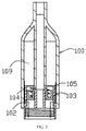
FIG. 1 is a cross-sectional view of an atomizer according to a first embodiment, including a liquid supply and an atomizing assembly separated from each other, the liquid supply including a sealing element. -
FIG. 2 is an assembled cross-sectional view of the atomizer ofFIG. 1 . -
FIG. 3 is a cross-sectional view of the liquid supply, showing a state when the sealing element is lifted to expose a liquid outlet. -
FIG. 4 is an exploded perspective view, showing a supporting holder, an elastic element, and a supporting holder ofFIG. 1 . -
FIG. 5 is a cross-sectional view of an electronic cigarette according to a second embodiment. - It will be appreciated that for simplicity and clarity of illustration, where appropriate, reference numerals have been repeated among the different figures to indicate corresponding or analogous elements. In addition, numerous specific details are set forth in order to provide a thorough understanding of the embodiments described herein. However, it will be understood by those of ordinary skill in the art that the embodiments described herein can be practiced without these specific details. In other instances, methods, procedures and components have not been described in detail so as not to obscure the related relevant feature being described. Also, the description is not to be considered as limiting the scope of the embodiments described herein. The drawings are not necessarily to scale and the proportions of certain parts have been exaggerated to better illustrate details and features of the present disclosure.
- The disclosure is illustrated by way of example and not by way of limitation in the figures of the accompanying drawings in which like references indicate similar elements. It should be noted that references to "an" or "one" embodiment in this disclosure are not necessarily to the same embodiment, and such references mean at least one.
- Several definitions that apply throughout this disclosure will now be presented.
- The term "outside" refers to a region that is beyond the outermost confines of a physical object. The term "inside" indicates that at least a portion of a region is partially contained within a boundary formed by the object. The term "substantially" is defined to be essentially conforming to the particular dimension, shape or other word that substantially modifies, such that the component need not be exact. For example, substantially cylindrical means that the object resembles a cylinder, but can have one or more deviations from a true cylinder. The term "comprising," when utilized, means "including, but not necessarily limited to"; it specifically indicates open-ended inclusion or membership in the so-described combination, group, series and the like.
- Referring to
FIG. 1 , anatomizer 10 includes an atomizingassembly 200 and aliquid supply 100 for storing tobacco liquid. Theatomizer 10 is configured for generating aerosol from the tobacco liquid. Theliquid supply 100 includes aconnection end 101, and the atomizingassembly 200 is detachably coupled with theconnection end 101. Theliquid supply 100 defines aliquid chamber 109 for receiving the tobacco liquid. In a non-use state (e.g., during transportation), theliquid supply 100 and the atomizingassembly 200 are separated from each other, and the tobacco liquid is sealed in theliquid chamber 109 by a sealing mechanism (described in detail later). When theliquid supply 100 and the atomizingassembly 200 are connected, the tobacco liquid in theliquid chamber 109 flows into the atomizingassembly 200. In the present embodiment, theliquid supply 100 and the atomizingassembly 200 are coupled threadedly. Theliquid supply 100 includes a plurality ofinternal threads 107 in theconnection end 101, and a plurality ofexternal threads 206 at one end of the atomizingassembly 200. - A structure of the sealing mechanism will be described in detail below. The
connection end 101 includes at least oneliquid outlet 102, through which the tobacco liquid in theliquid supply 100 flows into the atomizingassembly 200. The total quantity of theliquid outlets 102 may be adjusted by an amount of the aerosol needed. Theatomizer 10 further includes asealing element 103 and anelastic element 104 at the connection end. Thesealing element 103 is configured (i.e., structured and arranged) for sealing theliquid outlet 102. Theelastic element 104 abuts against the sealingelement 103. The sealingelement 103 is capable of moving up and down along an axis of theatomizer 10 relative to a housing of theliquid supply 100. In an inactive state, thesealing element 103 is kept in a suitable position (i.e., a first position) by theelastic element 104 where thesealing element 103 seals theliquid outlet 102. When theatomizer 200 is connected to theliquid supply 100, theatomizer 200 forces thesealing element 103 to move to a second position where theliquid outlet 102 is opened. In this state, the tobacco liquid flows into the atomizingassembly 200. When the atomizingassembly 200 is detached from theliquid supply 100, theelastic element 104 drives thesealing element 103 to return to the first position where thesealing element 103 seals theliquid outlet 102. It is to be understood that when the atomizingassembly 200 is detached from theliquid supply 100, the sealing mechanism at theconnection end 101 may be detached, so that tobacco liquid can be filled in theliquid chamber 109. - In detail, a supporting
holder 105 is fixed in theconnection end 101, and thesealing element 103 and theelastic element 104 are both arranged in the supportingholder 105. Theliquid outlet 102 is defined in a sidewall of the supportingholder 105. When the sealingelement 103 moves along an axial direction of the supportingholder 105, thesealing element 103 opens or closes theliquid outlet 102. The supportingholder 105 and the housing of theliquid supply 100 are both cylindrical. A tiny gap is cooperatively defined between an outer sidewall of the supportingholder 105 and an inner wall of the housing of theliquid supply 100. Theliquid outlet 102 is in communication with the gap, so that the tobacco liquid in theliquid chamber 109 can flow out slowly via theliquid outlet 102. Quite usefully, the supportingholder 105 defines a plurality ofliquid outlets 102, which are evenly arranged a circumferential direction. In this way, the tobacco liquid in theliquid chamber 109 can flow out more evenly. - Referring to
FIGS. 1 and4 , the supportingholder 105 defines anannular groove 111, and the sealingelement 103 and theelastic element 104 are both arranged in theannular groove 111. The sealingelement 103 is capable of moving along an axis of theannular groove 111. In the present embodiment, theelastic element 104 is a spring, and the sealingelement 103 is a silicone stopper. The sealingelement 103 is annular, and one end of the spring abuts against the silicone stopper. The supportingholder 105 includes atubular part 106 coaxial with a housing of the supportingholder 105. The supportingholder 105 includes a plurality ofinternal screws 107 formed on an interior wall. Thetubular part 106 and the interior wall of the supportingholder 105 cooperatively define the aboveannular groove 111. Thetubular part 106 is hollow, so that the aerosol can pass through thetubular part 106. The spring and the silicone stopper nest thetubular part 106, and thetubular part 106 guides the silicone stopper to move up and down. - The
liquid supply 100 includes anair pipe 108 inside. Theair pipe 108 and theliquid supply 100 are integrally formed. Theair pipe 108 and the housing of theliquid supply 100 cooperatively define an annular space serving as the aboveliquid chamber 109. An upper end of theair pipe 108 is connected with amouthpiece 110, and a lower end of theair pipe 108 is hermetically connected to thetubular part 106. Theair pipe 108 is configured for conveying the aerosol to themouthpiece 110 for inhalation. - Quite usefully, the
atomizing assembly 200 includes anatomizing chamber 201, aliquid conducting body 202 in theatomizing chamber 201, and aheating element 203 in theatomizing chamber 201. Theheating element 203 is in contact with theliquid conducting body 202. Theheating element 203 is configured for heating the tobacco liquid to form aerosol. Theatomizing chamber 201 includes an air inlet at a bottom part, and anaerosol outlet 205 at a top part. When theliquid supply 100 is connected with theatomizing assembly 200, a bottom end of thetubular part 106 is inserted in theaerosol outlet 205, and is hermetically connected with theaerosol outlet 205. The aerosol generated in theatomizing chamber 201 goes in thetubular part 106 and theair pipe 108 via theaerosol outlet 205. Theliquid conducting body 202 may be made of glass fiber material, porous ceramic, and so on. In the present embodiment, theliquid conducting body 202 is made of glass fiber material, and theheating element 203 includes a heating wire wound around theliquid conducting body 202. Theatomizing device 200 includes afirst electrode 207 and asecond electrode 208, and two ends of the heating wire are connected to the first and thesecond electrodes second electrodes first electrode 207 includes a plurality of screw threads, facilitating an electrical and mechanical connection between the atomizingassembly 200 and the power supply. - Quite usefully, to control a flowing speed of the tobacco liquid into the
atomizing chamber 201, a liquidabsorbing layer 204 is further arranged between the atomizingchamber 201 and theliquid outlet 102. The liquidabsorbing layer 204 is made of fiber cotton, and two ends of theliquid conducting body 202 are in contact with the liquidabsorbing layer 204. The liquidabsorbing layer 204 is configured for absorbing tobacco liquid flowing out from theliquid outlet 102, preventing too much tobacco liquid from directly flowing in theatomizing chamber 201. - Referring to
FIGS. 2-3 , when theatomizing assembly 200 is screwed in theconnection end 101 of theliquid supply 100, an upper end of theatomizing assembly 200 pushes the sealingelement 103 to move upwards, and theliquid outlet 102 in the supportingholder 105 is exposed. In this first position, theelastic element 104 is compressed, and theelastic element 104 drives a lower end of the sealingelement 103 to tightly abut against an upper end of theatomizing assembly 200. Due to flexibility of the sealingelement 103, the lower end of the sealingelement 103 is hermetically coupled with the upper end of theatomizing assembly 200, preventing the tobacco liquid from directly flowing into theatomizing chamber 201 via theaerosol outlet 205. After thesealing element 103 is pushed up, the tobacco liquid flows out from theliquid outlet 102 to the liquidabsorbing layer 204. The tobacco liquid is then conveyed to theheating element 203 by theliquid conducting body 202. - Referring to
FIG. 5 , anelectronic cigarette 30 includes the above mentionedatomizer 10, and apower supply 20 connected with theatomizer 10. Theatomizer assembly 200 defines anair inlet 209 in an exterior wall. Thepower supply 20 is cylindrical, and includes a battery and asmoking button 301. When thesmoking button 301 is pressed, theatomizer 10 is powered on to form aerosol. - It is understood that the above-described embodiments are intended to illustrate rather than limit the disclosure. Variations may be made to the embodiments and methods without departing from the spirit of the disclosure. Accordingly, it is appropriate that the appended claims be construed broadly and in a manner consistent with the scope of the disclosure.
Claims (10)
- An atomizer, comprising an atomizing assembly and a liquid supply configured for storing tobacco liquid, the liquid supply comprising a connection end, the atomizing assembly being detachably connected to the connection end, wherein the connection end defines at least one liquid outlet, through which the tobacco liquid in the liquid supply flows into the atomizing assembly, the atomizing assembly further comprises a sealing element and an elastic element, the sealing element is configured for sealing the liquid outlet when in a first position, and the elastic element abuts against the sealing element; when the atomizing assembly is connected with the liquid supply, the atomizing assembly is configured for driving the sealing element to move to a second position where the liquid outlet is opened; when the atomizing assembly is detached from the liquid supply, the atomizing assembly is configured for driving the sealing element to return to the first position where the sealing element seals the liquid outlet.
- The atomizer in accordance with claim 1, further comprising a supporting holder in the connection end, wherein the sealing element and the elastic element are arranged in the supporting holder, the at least one liquid outlet is defined in a sidewall of the supporting holder, and the sealing element is capable of moving along an axis of the supporting holder to open or close the liquid outlet.
- The atomizer in accordance with claim 2, wherein the supporting holder comprises an annular groove extending along the axis, the sealing element and the elastic element are both received in the annular groove, and the sealing element is capable of moving along an axis of the annular groove.
- The atomizer in accordance with claim 3, wherein the elastic element comprises a spring, the sealing element comprises a silicone stopper, the silicone stopper is annular, and an end of the spring abuts against the silicone stopper.
- The atomizer in accordance with claim 4, wherein the supporting holder comprises a tubular part, and the spring and the silicone stopper nest the tubular part.
- The atomizer in accordance with claim 5, wherein the liquid supply comprises an air pipe inside, and the air pipe is hermetically coupled with the tubular part.
- The atomizer in accordance with claim 2, wherein the at least one liquid outlet comprises a plurality of liquid outlets, and the liquid outlets are evenly arranged in the sidewall of the supporting holder along a circumferential direction.
- The atomizer in accordance with claim 1, wherein the atomizing assembly comprises an atomizing chamber, a liquid conducting body in the atomizing chamber, and a heating element in the atomizing chamber, the heating element contacts with the liquid conducting body, and the heating element is configured for heating the tobacco liquid to form aerosol.
- The atomizer in accordance with claim 8, further comprising a liquid absorbing layer between the atomizing chamber and the liquid outlet, wherein two opposite ends of the liquid conducting body is in contact with the liquid absorbing layer.
- An electronic cigarette, comprising:an atomizer according to any of claims 1-9; anda power supply connected with the atomizer, the power supply being configured for feeding the atomizer power.
Applications Claiming Priority (1)
| Application Number | Priority Date | Filing Date | Title |
|---|---|---|---|
| CN201520268222.1U CN204670386U (en) | 2015-04-29 | 2015-04-29 | Atomizer and use the electronic cigarette of this atomizer |
Publications (3)
| Publication Number | Publication Date |
|---|---|
| EP3025602A2 true EP3025602A2 (en) | 2016-06-01 |
| EP3025602A3 EP3025602A3 (en) | 2016-10-26 |
| EP3025602B1 EP3025602B1 (en) | 2018-10-03 |
Family
ID=54170125
Family Applications (1)
| Application Number | Title | Priority Date | Filing Date |
|---|---|---|---|
| EP16160048.1A Active EP3025602B1 (en) | 2015-04-29 | 2016-03-12 | Atomizer and electronic cigarette having same |
Country Status (3)
| Country | Link |
|---|---|
| US (1) | US10064433B2 (en) |
| EP (1) | EP3025602B1 (en) |
| CN (1) | CN204670386U (en) |
Cited By (10)
| Publication number | Priority date | Publication date | Assignee | Title |
|---|---|---|---|---|
| EP3135140A1 (en) * | 2015-11-04 | 2017-03-01 | Shenzhen First Union Technology Co., Ltd. | Liquid supply, atomizer and electronic cigarette having same |
| EP3138427A1 (en) * | 2015-11-25 | 2017-03-08 | Shenzhen First Union Technology Co., Ltd. | Liquid supply, atomizer and electronic cigarette having same |
| EP3289897A1 (en) * | 2016-11-02 | 2018-03-07 | Shenzhen First Union Technology Co., Ltd. | Atomizer and electronic cigarette having same |
| EP3292776A1 (en) * | 2016-09-12 | 2018-03-14 | Shenzhen First Union Technology Co., Ltd. | Atomizing device and electronic cigarette having same |
| EP3332658A3 (en) * | 2017-03-17 | 2018-08-08 | Shenzhen First Union Technology Co., Ltd. | Atomizer with easy assembly and disassembly and electronic cigarette having same |
| EP3329790A4 (en) * | 2015-07-30 | 2019-03-20 | Shenzhen Jinjia Technologies Co., Ltd. | Electronic atomization device with switch-closed atomizer and electronic simulation cigarette |
| WO2020115174A1 (en) * | 2018-12-05 | 2020-06-11 | Jt International Sa | Flight safe mode for aerosol inhaler |
| WO2020201703A1 (en) * | 2019-04-05 | 2020-10-08 | Nicoventures Trading Limited | Aerosol generating system |
| CN113693287A (en) * | 2020-05-20 | 2021-11-26 | 深圳市赛尔美电子科技有限公司 | Atomizer and control structure thereof |
| EP3935094A1 (en) * | 2019-03-05 | 2022-01-12 | Dow Global Technologies LLC | Two-component solvent-less adhesive composition |
Families Citing this family (54)
| Publication number | Priority date | Publication date | Assignee | Title |
|---|---|---|---|---|
| US10244793B2 (en) | 2005-07-19 | 2019-04-02 | Juul Labs, Inc. | Devices for vaporization of a substance |
| US10279934B2 (en) | 2013-03-15 | 2019-05-07 | Juul Labs, Inc. | Fillable vaporizer cartridge and method of filling |
| US10159282B2 (en) | 2013-12-23 | 2018-12-25 | Juul Labs, Inc. | Cartridge for use with a vaporizer device |
| KR102721939B1 (en) | 2013-12-23 | 2024-10-25 | 쥴 랩스, 인크. | Vaporization device systems and methods |
| USD825102S1 (en) | 2016-07-28 | 2018-08-07 | Juul Labs, Inc. | Vaporizer device with cartridge |
| USD842536S1 (en) | 2016-07-28 | 2019-03-05 | Juul Labs, Inc. | Vaporizer cartridge |
| US10058129B2 (en) | 2013-12-23 | 2018-08-28 | Juul Labs, Inc. | Vaporization device systems and methods |
| US20160366947A1 (en) | 2013-12-23 | 2016-12-22 | James Monsees | Vaporizer apparatus |
| US10076139B2 (en) | 2013-12-23 | 2018-09-18 | Juul Labs, Inc. | Vaporizer apparatus |
| WO2016054796A1 (en) * | 2014-10-10 | 2016-04-14 | 深圳麦克韦尔股份有限公司 | Inhaler and atomization component thereof |
| KR20250012730A (en) | 2014-12-05 | 2025-01-24 | 쥴 랩스, 인크. | Calibrated dose control |
| EP3153037B1 (en) * | 2015-02-06 | 2020-05-06 | O-Net Automation Technology Shenzhen Limited | Atomizer of electronic cigarette |
| CN105105341A (en) * | 2015-09-22 | 2015-12-02 | 深圳市杰仕博科技有限公司 | Leakage-preventing atomizer |
| CN105192896B (en) | 2015-10-28 | 2018-10-02 | 深圳麦克韦尔股份有限公司 | Tobacco tar and electronic cigarette |
| WO2017070871A1 (en) * | 2015-10-28 | 2017-05-04 | 深圳麦克韦尔股份有限公司 | Electronic cigarette atomizer |
| CN105212278B (en) * | 2015-10-28 | 2019-03-22 | 深圳麦克韦尔股份有限公司 | Electronic smoke atomizer |
| ES2863570T3 (en) | 2015-12-18 | 2021-10-11 | Jt Int Sa | Personal vaporizer device |
| CN105455199B (en) * | 2016-02-01 | 2018-09-14 | 深圳市新宜康科技股份有限公司 | The electronic smoke atomizer of replaceable smoke grenade |
| MX377347B (en) | 2016-02-11 | 2025-03-07 | Juul Labs Inc | Fillable vaporizer cartridge and method of filling |
| MX388616B (en) | 2016-02-11 | 2025-03-20 | Juul Labs Inc | SECURE FITTING CARTRIDGES FOR VAPORIZING DEVICES |
| US10405582B2 (en) | 2016-03-10 | 2019-09-10 | Pax Labs, Inc. | Vaporization device with lip sensing |
| KR102806225B1 (en) * | 2016-03-31 | 2025-05-13 | 필립모리스 프로덕츠 에스.에이. | Aerosol generating system with separate capsule and vaporizing unit |
| CA3011956A1 (en) * | 2016-03-31 | 2017-10-05 | Philip Morris Products S.A. | Aerosol generating system with separate capsule and vaporizing unit |
| CN105725280A (en) * | 2016-04-20 | 2016-07-06 | 深圳市杰仕博科技有限公司 | Anti-seepage atomizer |
| USD849996S1 (en) | 2016-06-16 | 2019-05-28 | Pax Labs, Inc. | Vaporizer cartridge |
| USD851830S1 (en) | 2016-06-23 | 2019-06-18 | Pax Labs, Inc. | Combined vaporizer tamp and pick tool |
| USD836541S1 (en) | 2016-06-23 | 2018-12-25 | Pax Labs, Inc. | Charging device |
| US10085485B2 (en) * | 2016-07-06 | 2018-10-02 | Rai Strategic Holdings, Inc. | Aerosol delivery device with a reservoir housing and a vaporizer assembly |
| WO2018018608A1 (en) * | 2016-07-29 | 2018-02-01 | 惠州市吉瑞科技有限公司深圳分公司 | Atomizing assembly and electronic cigarette |
| WO2018039876A1 (en) * | 2016-08-29 | 2018-03-08 | 惠州市吉瑞科技有限公司深圳分公司 | Cigarette liquid bottle and atomizer for electronic cigarette |
| CN108065452B (en) | 2016-11-18 | 2020-10-16 | 卓尔悦欧洲控股有限公司 | A kind of atomizer and electronic cigarette thereof |
| WO2018094564A1 (en) * | 2016-11-22 | 2018-05-31 | 常州聚为智能科技有限公司 | E-liquid storage assembly, atomizer, and electronic cigarette having same |
| WO2018111843A1 (en) | 2016-12-12 | 2018-06-21 | Vmr Products Llc | Vaporizer cartridge |
| CN206603253U (en) * | 2017-03-13 | 2017-11-03 | 深圳市宜友国际科技有限公司 | It is atomized chamber structure |
| US11160940B2 (en) * | 2017-06-02 | 2021-11-02 | Jt International S.A. | Aerosol generation system with replaceable atomizer |
| USD887632S1 (en) | 2017-09-14 | 2020-06-16 | Pax Labs, Inc. | Vaporizer cartridge |
| CN108185536B (en) | 2018-02-13 | 2020-01-21 | 深圳麦克韦尔科技有限公司 | Electronic cigarette and its atomizer |
| CN110946329B (en) * | 2018-09-26 | 2022-08-16 | 常州市派腾电子技术服务有限公司 | Atomizer and electronic cigarette |
| CN109363241A (en) * | 2018-10-29 | 2019-02-22 | 刘太军 | Electronic cigarette and its atomizer |
| KR102817701B1 (en) | 2018-11-05 | 2025-06-09 | 쥴 랩스, 인크. | Cartridge for vaporizer device |
| MX2021006339A (en) * | 2018-12-07 | 2021-08-11 | Philip Morris Products Sa | Aerosol-generating system and cartridge with leakage protection. |
| US11181199B2 (en) | 2019-06-04 | 2021-11-23 | 14Th Round Inc. | Assembly for preventing leakage in a vaporization device |
| CN110292210B (en) * | 2019-06-26 | 2024-06-18 | 深圳市你我网络科技有限公司 | Atomizer and electronic cigarette |
| CN114269173A (en) * | 2019-08-30 | 2022-04-01 | 日本烟草国际股份有限公司 | Nozzle part for electronic cigarette |
| CN211746944U (en) * | 2020-02-25 | 2020-10-27 | 常州市派腾电子技术服务有限公司 | Nebulizer and aerosol generating device |
| CN212065675U (en) * | 2020-03-19 | 2020-12-04 | 常州市派腾电子技术服务有限公司 | Atomizer and aerosol generating device |
| CN112006331A (en) * | 2020-08-25 | 2020-12-01 | 深圳易佳特科技有限公司 | Environment-friendly glass atomizer |
| US11871785B2 (en) * | 2020-08-25 | 2024-01-16 | Aspire North America Llc | Atomizer having inner and outer glass tubes |
| CN113966874B (en) * | 2021-12-10 | 2025-08-22 | 深圳市吉迩科技有限公司 | Aerosol generating device |
| CN222031475U (en) * | 2024-02-04 | 2024-11-22 | 派克斯创新(深圳)科技有限公司 | Electronic cigarette component |
| DE202024103630U1 (en) * | 2024-02-04 | 2024-09-04 | PAX Innovations (Shenzhen) Limited | e-cigarette assembly |
| GB2637815A (en) * | 2024-02-04 | 2025-08-06 | Pax Innovations Shenzhen Ltd | Electronic cigarette liquid bottle and cartridge structure |
| EP4595793A1 (en) * | 2024-02-04 | 2025-08-06 | PAX Innovations (Shenzhen) Limited | Electronic cigarette assembly with replaceable atomizing core |
| EP4606236A1 (en) * | 2024-02-23 | 2025-08-27 | JT International SA | Aerosol generating systems and cartomizers therefor |
Family Cites Families (17)
| Publication number | Priority date | Publication date | Assignee | Title |
|---|---|---|---|---|
| FR2253980A1 (en) * | 1973-12-10 | 1975-07-04 | Rosenthal Claude | |
| GB0712305D0 (en) * | 2007-06-25 | 2007-08-01 | Kind Group Ltd | A system comprising a simulated cigarette device and a refill unit |
| CN201379072Y (en) * | 2009-02-11 | 2010-01-13 | 韩力 | An improved atomized electronic cigarette |
| US8528569B1 (en) * | 2011-06-28 | 2013-09-10 | Kyle D. Newton | Electronic cigarette with liquid reservoir |
| CN202407081U (en) * | 2011-12-21 | 2012-09-05 | 刘秋明 | imitation smoke |
| KR101184758B1 (en) * | 2012-01-13 | 2012-09-19 | 이영인 | Cartridge of electric cigarette for preventing leakage |
| CN202618275U (en) * | 2012-04-01 | 2012-12-26 | 惠州市吉瑞科技有限公司 | Electronic cigarette and suction nozzle thereof |
| AU2012381926B2 (en) * | 2012-06-05 | 2015-08-27 | Huizhou Kimree Technology Co., Ltd., Shenzhen Branch | Electronic cigarette and suction rod thereof |
| GB2515992A (en) * | 2013-03-22 | 2015-01-14 | British American Tobacco Co | Heating smokeable material |
| WO2014166028A1 (en) * | 2013-04-07 | 2014-10-16 | Liu Qiuming | Electronic cigarette seal ring and electronic cigarette atomizer |
| US20150181939A1 (en) * | 2013-04-09 | 2015-07-02 | Kimree Hi-Tech Inc., | Electronic cigarette |
| ES2846764T3 (en) * | 2013-06-03 | 2021-07-29 | Old Navigators Ltd | Electronic cigarette with enhanced security |
| CN103300480B (en) * | 2013-06-06 | 2015-05-13 | 深圳市康尔科技有限公司 | Leak-proof atomizer |
| CN204599325U (en) * | 2014-04-30 | 2015-09-02 | 惠州市吉瑞科技有限公司 | Electronic cigarette |
| WO2016004576A1 (en) * | 2014-07-08 | 2016-01-14 | 深圳市康尔科技有限公司 | Electronic cigarette allowing liquid to be injected from top and heating assembly to be replaced at bottom |
| CN204232301U (en) * | 2014-11-13 | 2015-04-01 | 深圳市合元科技有限公司 | Atomizer and electronic cigarette |
| US20160332754A1 (en) * | 2015-05-13 | 2016-11-17 | Fontem Holdings 4 B.V. | Device for refilling electronic cigarette cartridge |
-
2015
- 2015-04-29 CN CN201520268222.1U patent/CN204670386U/en not_active Expired - Lifetime
-
2016
- 2016-03-08 US US15/064,597 patent/US10064433B2/en active Active
- 2016-03-12 EP EP16160048.1A patent/EP3025602B1/en active Active
Non-Patent Citations (1)
| Title |
|---|
| None |
Cited By (18)
| Publication number | Priority date | Publication date | Assignee | Title |
|---|---|---|---|---|
| EP3329790A4 (en) * | 2015-07-30 | 2019-03-20 | Shenzhen Jinjia Technologies Co., Ltd. | Electronic atomization device with switch-closed atomizer and electronic simulation cigarette |
| EP3135140A1 (en) * | 2015-11-04 | 2017-03-01 | Shenzhen First Union Technology Co., Ltd. | Liquid supply, atomizer and electronic cigarette having same |
| EP3138427A1 (en) * | 2015-11-25 | 2017-03-08 | Shenzhen First Union Technology Co., Ltd. | Liquid supply, atomizer and electronic cigarette having same |
| US10786636B2 (en) | 2016-09-12 | 2020-09-29 | Shenzhen First Union Technology Co., Ltd. | Atomizing device and electronic cigarette having same |
| EP3292776A1 (en) * | 2016-09-12 | 2018-03-14 | Shenzhen First Union Technology Co., Ltd. | Atomizing device and electronic cigarette having same |
| EP3289897A1 (en) * | 2016-11-02 | 2018-03-07 | Shenzhen First Union Technology Co., Ltd. | Atomizer and electronic cigarette having same |
| US10537138B2 (en) | 2016-11-02 | 2020-01-21 | Shenzhen First Union Technology Co., Ltd. | Atomizer and electronic cigarette having same |
| EP3332658A3 (en) * | 2017-03-17 | 2018-08-08 | Shenzhen First Union Technology Co., Ltd. | Atomizer with easy assembly and disassembly and electronic cigarette having same |
| US10849362B2 (en) | 2017-03-17 | 2020-12-01 | Shenzhen First Union Technology Co., Ltd. | Atomizer with easy assembly and disassembly and electronic cigarette having same |
| WO2020115175A1 (en) * | 2018-12-05 | 2020-06-11 | Jt International Sa | Aerosol inhaler mouthpiece with valve |
| WO2020115174A1 (en) * | 2018-12-05 | 2020-06-11 | Jt International Sa | Flight safe mode for aerosol inhaler |
| CN113163864A (en) * | 2018-12-05 | 2021-07-23 | Jt国际公司 | Aerosol inhaler mouthpiece with valve |
| US11998055B2 (en) | 2018-12-05 | 2024-06-04 | Jt International S.A. | Atomizer ejection mechanism for aerosol inhaler |
| EP3935094A1 (en) * | 2019-03-05 | 2022-01-12 | Dow Global Technologies LLC | Two-component solvent-less adhesive composition |
| WO2020201703A1 (en) * | 2019-04-05 | 2020-10-08 | Nicoventures Trading Limited | Aerosol generating system |
| JP2022528395A (en) * | 2019-04-05 | 2022-06-10 | ニコベンチャーズ トレーディング リミテッド | Aerosol generation system |
| US12342862B2 (en) | 2019-04-05 | 2025-07-01 | Nicoventures Trading Limited | Aerosol generating system |
| CN113693287A (en) * | 2020-05-20 | 2021-11-26 | 深圳市赛尔美电子科技有限公司 | Atomizer and control structure thereof |
Also Published As
| Publication number | Publication date |
|---|---|
| CN204670386U (en) | 2015-09-30 |
| EP3025602B1 (en) | 2018-10-03 |
| US10064433B2 (en) | 2018-09-04 |
| EP3025602A3 (en) | 2016-10-26 |
| US20160183597A1 (en) | 2016-06-30 |
Similar Documents
| Publication | Publication Date | Title |
|---|---|---|
| EP3025602B1 (en) | Atomizer and electronic cigarette having same | |
| US9814269B2 (en) | Atomizing device and electronic cigarette having same | |
| US9968133B2 (en) | Atomizer and electronic cigarette having same | |
| US9848649B2 (en) | Atomizer and electronic cigarette having same | |
| EP3040095B1 (en) | Atomizer and electronic cigarette having same | |
| US10070668B2 (en) | Replaceable atomizing unit, atomizer and electronic cigarette having same | |
| US10660367B2 (en) | Liquid supply, atomizer and electronic cigarette having same | |
| EP2946679B1 (en) | Atomizer and electronic cigarette having same | |
| US9993028B2 (en) | Atomizer having replaceable atomizing core and electronic cigarette having same | |
| EP3095339A1 (en) | Atomizing head, atomizer and electronic cigarette having same | |
| US10791759B2 (en) | Liquid supply, atomizer and electronic cigarette having same | |
| US10064431B2 (en) | Atomizer and electronic cigarette having same | |
| EP2965642A1 (en) | Atomizer and electronic cigarette having same | |
| EP3195741A2 (en) | Electronic cigarette | |
| EP2965641A1 (en) | Atomizing head, atomizer and electronic cigarette having same | |
| CN106455690B (en) | Electronic cigarette and its manufacturing method | |
| US20150144147A1 (en) | Atomizer and electronic cigarette having same | |
| EP2954791A1 (en) | Atomizer and electronic cigarette having same | |
| EP3195740A1 (en) | Electronic cigarette comprising an internal shipping plug | |
| EP3254573A1 (en) | Atomizer and electronic cigarette having same | |
| EP2837297A1 (en) | Atomizer and electronic cigarette having same | |
| EP3095338A1 (en) | Atomizer and electric cigarette having the same | |
| EP3162403A1 (en) | Atomizer and electronic cigarette having same | |
| CN106028847A (en) | Atomizing apparatus, electronic cigarette, and oil supply control method |
Legal Events
| Date | Code | Title | Description |
|---|---|---|---|
| PUAI | Public reference made under article 153(3) epc to a published international application that has entered the european phase |
Free format text: ORIGINAL CODE: 0009012 |
|
| 17P | Request for examination filed |
Effective date: 20160318 |
|
| AK | Designated contracting states |
Kind code of ref document: A2 Designated state(s): AL AT BE BG CH CY CZ DE DK EE ES FI FR GB GR HR HU IE IS IT LI LT LU LV MC MK MT NL NO PL PT RO RS SE SI SK SM TR |
|
| AX | Request for extension of the european patent |
Extension state: BA ME |
|
| PUAL | Search report despatched |
Free format text: ORIGINAL CODE: 0009013 |
|
| AK | Designated contracting states |
Kind code of ref document: A3 Designated state(s): AL AT BE BG CH CY CZ DE DK EE ES FI FR GB GR HR HU IE IS IT LI LT LU LV MC MK MT NL NO PL PT RO RS SE SI SK SM TR |
|
| AX | Request for extension of the european patent |
Extension state: BA ME |
|
| RIC1 | Information provided on ipc code assigned before grant |
Ipc: A24F 47/00 20060101AFI20160919BHEP Ipc: H05B 1/02 20060101ALN20160919BHEP Ipc: H05B 3/00 20060101ALN20160919BHEP |
|
| GRAP | Despatch of communication of intention to grant a patent |
Free format text: ORIGINAL CODE: EPIDOSNIGR1 |
|
| STAA | Information on the status of an ep patent application or granted ep patent |
Free format text: STATUS: GRANT OF PATENT IS INTENDED |
|
| RIC1 | Information provided on ipc code assigned before grant |
Ipc: H05B 1/02 20060101ALN20180427BHEP Ipc: H05B 3/00 20060101ALN20180427BHEP Ipc: A24F 47/00 20060101AFI20180427BHEP |
|
| INTG | Intention to grant announced |
Effective date: 20180518 |
|
| RIN1 | Information on inventor provided before grant (corrected) |
Inventor name: DUAN, HONGXING Inventor name: LI, YONGHAI Inventor name: XU, ZHONGLI |
|
| GRAS | Grant fee paid |
Free format text: ORIGINAL CODE: EPIDOSNIGR3 |
|
| GRAA | (expected) grant |
Free format text: ORIGINAL CODE: 0009210 |
|
| STAA | Information on the status of an ep patent application or granted ep patent |
Free format text: STATUS: THE PATENT HAS BEEN GRANTED |
|
| AK | Designated contracting states |
Kind code of ref document: B1 Designated state(s): AL AT BE BG CH CY CZ DE DK EE ES FI FR GB GR HR HU IE IS IT LI LT LU LV MC MK MT NL NO PL PT RO RS SE SI SK SM TR |
|
| REG | Reference to a national code |
Ref country code: GB Ref legal event code: FG4D |
|
| REG | Reference to a national code |
Ref country code: CH Ref legal event code: EP Ref country code: AT Ref legal event code: REF Ref document number: 1047664 Country of ref document: AT Kind code of ref document: T Effective date: 20181015 |
|
| REG | Reference to a national code |
Ref country code: IE Ref legal event code: FG4D Ref country code: DE Ref legal event code: R096 Ref document number: 602016006136 Country of ref document: DE |
|
| REG | Reference to a national code |
Ref country code: NL Ref legal event code: FP |
|
| REG | Reference to a national code |
Ref country code: LT Ref legal event code: MG4D |
|
| REG | Reference to a national code |
Ref country code: AT Ref legal event code: MK05 Ref document number: 1047664 Country of ref document: AT Kind code of ref document: T Effective date: 20181003 |
|
| PG25 | Lapsed in a contracting state [announced via postgrant information from national office to epo] |
Ref country code: IS Free format text: LAPSE BECAUSE OF FAILURE TO SUBMIT A TRANSLATION OF THE DESCRIPTION OR TO PAY THE FEE WITHIN THE PRESCRIBED TIME-LIMIT Effective date: 20190203 Ref country code: ES Free format text: LAPSE BECAUSE OF FAILURE TO SUBMIT A TRANSLATION OF THE DESCRIPTION OR TO PAY THE FEE WITHIN THE PRESCRIBED TIME-LIMIT Effective date: 20181003 Ref country code: CZ Free format text: LAPSE BECAUSE OF FAILURE TO SUBMIT A TRANSLATION OF THE DESCRIPTION OR TO PAY THE FEE WITHIN THE PRESCRIBED TIME-LIMIT Effective date: 20181003 Ref country code: LT Free format text: LAPSE BECAUSE OF FAILURE TO SUBMIT A TRANSLATION OF THE DESCRIPTION OR TO PAY THE FEE WITHIN THE PRESCRIBED TIME-LIMIT Effective date: 20181003 Ref country code: PL Free format text: LAPSE BECAUSE OF FAILURE TO SUBMIT A TRANSLATION OF THE DESCRIPTION OR TO PAY THE FEE WITHIN THE PRESCRIBED TIME-LIMIT Effective date: 20181003 Ref country code: NO Free format text: LAPSE BECAUSE OF FAILURE TO SUBMIT A TRANSLATION OF THE DESCRIPTION OR TO PAY THE FEE WITHIN THE PRESCRIBED TIME-LIMIT Effective date: 20190103 Ref country code: AT Free format text: LAPSE BECAUSE OF FAILURE TO SUBMIT A TRANSLATION OF THE DESCRIPTION OR TO PAY THE FEE WITHIN THE PRESCRIBED TIME-LIMIT Effective date: 20181003 Ref country code: BG Free format text: LAPSE BECAUSE OF FAILURE TO SUBMIT A TRANSLATION OF THE DESCRIPTION OR TO PAY THE FEE WITHIN THE PRESCRIBED TIME-LIMIT Effective date: 20190103 Ref country code: HR Free format text: LAPSE BECAUSE OF FAILURE TO SUBMIT A TRANSLATION OF THE DESCRIPTION OR TO PAY THE FEE WITHIN THE PRESCRIBED TIME-LIMIT Effective date: 20181003 Ref country code: FI Free format text: LAPSE BECAUSE OF FAILURE TO SUBMIT A TRANSLATION OF THE DESCRIPTION OR TO PAY THE FEE WITHIN THE PRESCRIBED TIME-LIMIT Effective date: 20181003 Ref country code: LV Free format text: LAPSE BECAUSE OF FAILURE TO SUBMIT A TRANSLATION OF THE DESCRIPTION OR TO PAY THE FEE WITHIN THE PRESCRIBED TIME-LIMIT Effective date: 20181003 |
|
| PG25 | Lapsed in a contracting state [announced via postgrant information from national office to epo] |
Ref country code: RS Free format text: LAPSE BECAUSE OF FAILURE TO SUBMIT A TRANSLATION OF THE DESCRIPTION OR TO PAY THE FEE WITHIN THE PRESCRIBED TIME-LIMIT Effective date: 20181003 Ref country code: AL Free format text: LAPSE BECAUSE OF FAILURE TO SUBMIT A TRANSLATION OF THE DESCRIPTION OR TO PAY THE FEE WITHIN THE PRESCRIBED TIME-LIMIT Effective date: 20181003 Ref country code: SE Free format text: LAPSE BECAUSE OF FAILURE TO SUBMIT A TRANSLATION OF THE DESCRIPTION OR TO PAY THE FEE WITHIN THE PRESCRIBED TIME-LIMIT Effective date: 20181003 Ref country code: GR Free format text: LAPSE BECAUSE OF FAILURE TO SUBMIT A TRANSLATION OF THE DESCRIPTION OR TO PAY THE FEE WITHIN THE PRESCRIBED TIME-LIMIT Effective date: 20190104 Ref country code: PT Free format text: LAPSE BECAUSE OF FAILURE TO SUBMIT A TRANSLATION OF THE DESCRIPTION OR TO PAY THE FEE WITHIN THE PRESCRIBED TIME-LIMIT Effective date: 20190203 |
|
| REG | Reference to a national code |
Ref country code: DE Ref legal event code: R097 Ref document number: 602016006136 Country of ref document: DE |
|
| PG25 | Lapsed in a contracting state [announced via postgrant information from national office to epo] |
Ref country code: DK Free format text: LAPSE BECAUSE OF FAILURE TO SUBMIT A TRANSLATION OF THE DESCRIPTION OR TO PAY THE FEE WITHIN THE PRESCRIBED TIME-LIMIT Effective date: 20181003 |
|
| PLBE | No opposition filed within time limit |
Free format text: ORIGINAL CODE: 0009261 |
|
| STAA | Information on the status of an ep patent application or granted ep patent |
Free format text: STATUS: NO OPPOSITION FILED WITHIN TIME LIMIT |
|
| PG25 | Lapsed in a contracting state [announced via postgrant information from national office to epo] |
Ref country code: SM Free format text: LAPSE BECAUSE OF FAILURE TO SUBMIT A TRANSLATION OF THE DESCRIPTION OR TO PAY THE FEE WITHIN THE PRESCRIBED TIME-LIMIT Effective date: 20181003 Ref country code: EE Free format text: LAPSE BECAUSE OF FAILURE TO SUBMIT A TRANSLATION OF THE DESCRIPTION OR TO PAY THE FEE WITHIN THE PRESCRIBED TIME-LIMIT Effective date: 20181003 Ref country code: RO Free format text: LAPSE BECAUSE OF FAILURE TO SUBMIT A TRANSLATION OF THE DESCRIPTION OR TO PAY THE FEE WITHIN THE PRESCRIBED TIME-LIMIT Effective date: 20181003 Ref country code: SK Free format text: LAPSE BECAUSE OF FAILURE TO SUBMIT A TRANSLATION OF THE DESCRIPTION OR TO PAY THE FEE WITHIN THE PRESCRIBED TIME-LIMIT Effective date: 20181003 |
|
| 26N | No opposition filed |
Effective date: 20190704 |
|
| PG25 | Lapsed in a contracting state [announced via postgrant information from national office to epo] |
Ref country code: MC Free format text: LAPSE BECAUSE OF FAILURE TO SUBMIT A TRANSLATION OF THE DESCRIPTION OR TO PAY THE FEE WITHIN THE PRESCRIBED TIME-LIMIT Effective date: 20181003 Ref country code: SI Free format text: LAPSE BECAUSE OF FAILURE TO SUBMIT A TRANSLATION OF THE DESCRIPTION OR TO PAY THE FEE WITHIN THE PRESCRIBED TIME-LIMIT Effective date: 20181003 |
|
| PG25 | Lapsed in a contracting state [announced via postgrant information from national office to epo] |
Ref country code: LU Free format text: LAPSE BECAUSE OF NON-PAYMENT OF DUE FEES Effective date: 20190312 |
|
| REG | Reference to a national code |
Ref country code: BE Ref legal event code: MM Effective date: 20190331 |
|
| PG25 | Lapsed in a contracting state [announced via postgrant information from national office to epo] |
Ref country code: BE Free format text: LAPSE BECAUSE OF NON-PAYMENT OF DUE FEES Effective date: 20190331 |
|
| PG25 | Lapsed in a contracting state [announced via postgrant information from national office to epo] |
Ref country code: TR Free format text: LAPSE BECAUSE OF FAILURE TO SUBMIT A TRANSLATION OF THE DESCRIPTION OR TO PAY THE FEE WITHIN THE PRESCRIBED TIME-LIMIT Effective date: 20181003 |
|
| PG25 | Lapsed in a contracting state [announced via postgrant information from national office to epo] |
Ref country code: MT Free format text: LAPSE BECAUSE OF NON-PAYMENT OF DUE FEES Effective date: 20190312 |
|
| PG25 | Lapsed in a contracting state [announced via postgrant information from national office to epo] |
Ref country code: CY Free format text: LAPSE BECAUSE OF FAILURE TO SUBMIT A TRANSLATION OF THE DESCRIPTION OR TO PAY THE FEE WITHIN THE PRESCRIBED TIME-LIMIT Effective date: 20181003 |
|
| PG25 | Lapsed in a contracting state [announced via postgrant information from national office to epo] |
Ref country code: HU Free format text: LAPSE BECAUSE OF FAILURE TO SUBMIT A TRANSLATION OF THE DESCRIPTION OR TO PAY THE FEE WITHIN THE PRESCRIBED TIME-LIMIT; INVALID AB INITIO Effective date: 20160312 |
|
| PG25 | Lapsed in a contracting state [announced via postgrant information from national office to epo] |
Ref country code: MK Free format text: LAPSE BECAUSE OF FAILURE TO SUBMIT A TRANSLATION OF THE DESCRIPTION OR TO PAY THE FEE WITHIN THE PRESCRIBED TIME-LIMIT Effective date: 20181003 |
|
| P01 | Opt-out of the competence of the unified patent court (upc) registered |
Free format text: CASE NUMBER: APP_8809/2025 Effective date: 20250220 |
|
| PGFP | Annual fee paid to national office [announced via postgrant information from national office to epo] |
Ref country code: CH Payment date: 20250401 Year of fee payment: 10 |
|
| PGFP | Annual fee paid to national office [announced via postgrant information from national office to epo] |
Ref country code: NL Payment date: 20260226 Year of fee payment: 11 |
|
| REG | Reference to a national code |
Ref country code: CH Ref legal event code: U11 Free format text: ST27 STATUS EVENT CODE: U-0-0-U10-U11 (AS PROVIDED BY THE NATIONAL OFFICE) Effective date: 20260401 |
|
| PGFP | Annual fee paid to national office [announced via postgrant information from national office to epo] |
Ref country code: GB Payment date: 20260323 Year of fee payment: 11 |
|
| PGFP | Annual fee paid to national office [announced via postgrant information from national office to epo] |
Ref country code: DE Payment date: 20260313 Year of fee payment: 11 Ref country code: IE Payment date: 20260224 Year of fee payment: 11 |
|
| PGFP | Annual fee paid to national office [announced via postgrant information from national office to epo] |
Ref country code: IT Payment date: 20260310 Year of fee payment: 11 |
|
| PGFP | Annual fee paid to national office [announced via postgrant information from national office to epo] |
Ref country code: FR Payment date: 20260330 Year of fee payment: 11 |