EP3025206B1 - Device and method for optimising the movement of automated-guided vehicles - Google Patents
Device and method for optimising the movement of automated-guided vehicles Download PDFInfo
- Publication number
- EP3025206B1 EP3025206B1 EP14771380.4A EP14771380A EP3025206B1 EP 3025206 B1 EP3025206 B1 EP 3025206B1 EP 14771380 A EP14771380 A EP 14771380A EP 3025206 B1 EP3025206 B1 EP 3025206B1
- Authority
- EP
- European Patent Office
- Prior art keywords
- node
- vehicle
- automated
- vehicles
- mission
- Prior art date
- Legal status (The legal status is an assumption and is not a legal conclusion. Google has not performed a legal analysis and makes no representation as to the accuracy of the status listed.)
- Active
Links
Images
Classifications
-
- G—PHYSICS
- G05—CONTROLLING; REGULATING
- G05D—SYSTEMS FOR CONTROLLING OR REGULATING NON-ELECTRIC VARIABLES
- G05D1/00—Control of position, course, altitude or attitude of land, water, air or space vehicles, e.g. using automatic pilots
- G05D1/02—Control of position or course in two dimensions
- G05D1/021—Control of position or course in two dimensions specially adapted to land vehicles
- G05D1/0287—Control of position or course in two dimensions specially adapted to land vehicles involving a plurality of land vehicles, e.g. fleet or convoy travelling
- G05D1/0291—Fleet control
- G05D1/0297—Fleet control by controlling means in a control room
Definitions
- the present invention concerns a device and a method for optimising the movement of automated-guided vehicles, and the like.
- the present invention concerns a device and a method that makes it possible to optimise the movement of automated-guided vehicles used for example in various kinds of warehouses for transporting articles, so as to improve the routes that the vehicles must follow to reach the different stations, decreasing the transportation times of the articles, and preventing the creation of jams along the routes themselves.
- automated-guided vehicles such vehicles also being called AGV in its abbreviated form from the English words Automated Guided Vehicle.
- AGV Automated Guided Vehicle
- Such vehicles are for example widely used in various kinds of industrial warehouses for transporting articles of all kinds inside the warehouse.
- the articles for which AGVs are used can belong to different fields such as the ceramic field, the food field, the so-called beverage field, i.e. bottles, cans and the like, the so-called tissue field, i.e. rolls of paper in general and the like, the mechanical field for moving semi-worked products and finished pieces, etc..
- Such automated-guided vehicles can be of various types, and all cases a role of primary importance is the management of the routes followed by them, so as to execute the assigned missions - for example transporting articles between the various stations - with efficiency and speed.
- Known devices for managing the routes of automated-guided vehicles comprise, amongst other things, a so-called connection graph, i.e. a scheme of the possible routes through which the vehicles must be guided.
- the scheme of the routes consists of a certain number of nodes and segments that connect the nodes themselves.
- the whole size is calculated, i.e. the whole of the segments and nodes for which the calculated shape intersects with the shape of the segment considered.
- incompatible segments and nodes are defined as block sizes for the segment considered.
- a predetermined segment can be assigned to a vehicle only if:
- each segment has a release point, which is precisely the point of the segment that must be passed by a vehicle before the node can be declared free and can be engaged by another vehicle.
- deadlocks i.e. AGV holdups or blocks.
- the purpose of the present invention is therefore to propose a device and a method for optimising the movement of automated-guided vehicles, and the like, which improves the routes that the vehicles must follow to reach the different stations to carry out the assigned missions, so as to decrease the times necessary for example for the transportation of articles between the different stations, and preventing interference from being caused between the automated-guided vehicles along the routes themselves, especially in the case in which a large number of automated-guided vehicles is used.
- a particular purpose of the present invention is to make a device and method for optimising the movement of automated-guided vehicles, and the like, which allows the total nominal travel time of all of the routes carried out by the whole vehicle fleet in a certain area or warehouse to be decreased, thus obtaining a saving, not just of time, but also of money.
- the nominal travel time is defined as the sum of the nominal travel times of each segment of the route, determined as the ratio between the length and the nominal speed of the vehicle on each segment.
- the device for optimising the movement of automated-guided vehicles essentially comprises:
- the optimisation device 20 can optionally comprise a higher-level supervisor module 23, hence indicated in figure 1 with a broken line. This supervisor module is in turn in communication with the traffic management module 21 and with the solving module 25.
- the supervisor module Among the tasks of the supervisor module is the preliminary selection, in the medium term, of the routes, the advance allocation of routes to particular AGVs through optimising criteria, the sequencing of the loading and unloading missions so as to "pre-plan" the traffic.
- the optimisation device 20 also comprises a memory 26 in which the plan of the warehouse - the so-called layout - or the area in which the vehicles AGV must move is represented, and from this layout of the warehouse it is then possible to obtain the connection graph that is located in the respective connection graph module 27, which comprises an outline of the possible routes for the vehicles AGV.
- the connection graph is then used by the traffic management module 21 to move the vehicles AGV.
- the traffic management module 21 receives the data from the connection graph module 27 and the overall state of the system, i.e. the current position of the vehicles AGV, the missions that the vehicles must carry out, etc.
- the traffic management module 21 calculates, for each AGV, a reduced connection graph, i.e. a graph that is formed from the general graph portion that the AGV can actually reach in a predetermined number of steps, hereafter indicated as time frame T.
- a reduced connection graph i.e. a graph that is formed from the general graph portion that the AGV can actually reach in a predetermined number of steps, hereafter indicated as time frame T.
- This information i.e. the overall state of the system and the reduced connection graph for each vehicle AGV, are then passed to the solving module 25, which reprocesses it through an integer linear programming model, discussed hereafter, providing an optimised preliminary solution of the routes, in the form of a sequence of segments that each vehicle AGV must travel.
- the traffic management module 21 must check the actual compatibility of the solution and thus check the assignments of the route segments to the vehicles in question.
- the solving module 25 provides a sequence of segments "b” and "c” for the vehicle AGV1, whereas for the vehicle AGV2, it provides the sequence of segments "a” and "d".
- the device 21 carries out the following activities:
- the reassignment module 24 is recalled, which reassigns the AGVs - among those that can be reassigned - to activate the missions.
- the vehicles AGV that can be reassigned are those that are not connected, by this term meaning the vehicles AGV engaged in a mission from the start moment of picking up a load of products up to the end of unloading of the load.
- the reassignment module 24 assigns the missions to the vehicles AGV in a mathematically optimised manner, i.e. minimising the sum of the nominal time relative to the shortest routes (i.e. the routes that allow the destination to be reached in the shortest time possible without considering possible deviations needed to avoid "jams") that the vehicles must carry out to move from the final node of the segment assigned up to that moment to the respective mission destination nodes.
- the reassignment module 24 reassigns the missions to the vehicles AGV, minimising the sum of the travel times of the vehicles themselves until the respective mission objective has been reached.
- the objective function to be minimised is the sum of all the nominal travel times from the final point of each vehicle AGV, meaning the point in which the given segments end up to that moment.
- the aforementioned sum of all the distances is calculated in advance based on the predetermined routes, for each pair of nodes, through an algorithm for calculating the minimum routes (like for example the known Dijkstra algorithm).
- each node of the connection graph has an associated matrix that comprises all of the minimum nominal times towards the other nodes, calculated with the calculation algorithm of the minimum routes.
- the solving module 25 generates an integer linear programming model using the data received from the traffic management module 21.
- the solving module 25 comprises a memory in which the elements of the integer linear programming that define the system are recorded: variables, coefficients of the objective function, matrix of the constraints; the solving module 25 also comprises an actual linear solver.
- the solving module uses an approximate linear model, in which:
- the calculation of the minimum distances between each pair of nodes of the connection graph is carried out.
- a calculation is carried out, for example, through the Dijkstra algorithm, then a matrix is associated to each node of the graph that comprises all the minimum distances towards the other nodes.
- the incompatibilities of the routes for the vehicles AGV identified are verified, in advance, through the analysis of the graph.
- the pair of segments (1,2) and (5,4) can also have the same problem: after assignment to two different vehicles AGV, the vehicle on the node 4. can only travel along the segment (4,3), which is incompatible with the segment (1,2). As a result the segments (1,2) and (5,4) also have a so-called static incompatibility, which will be discussed hereafter.
- the scheme of figure 3 represents another example of incompatibility with 3 segments.
- a first vehicle AGV1 is routed on the segment (8,1)
- a second vehicle AGV2 is routed on the segment (7,2)
- a third vehicle AGV3 is routed on the segment (9,3)
- the segment (1,4) for the first vehicle is blocked by the node 2
- the segment (2,5) for the second vehicle is blocked by the node 3
- the segment (3,6) for the third vehicle is blocked by the node 1.
- connection graph i.e. through a suitable algorithm the details of which will be provided hereafter.
- the solving module 25 will apply suitable constraints to prevent the AGVs from being located on such groups of incompatible segments.
- One particular case to be considered is that of two-directional segments. In general, it is better to avoid a vehicle AGV continuing to move back and forth on two-directional segments: this situation is comparable to the above indicated livelocks and, even when it does not take the system into an irresolvable condition, it causes a loss of time and, therefore, a drop in performance.
- the last segment assigned to a vehicle not to be such that its final node hinders, in the sense of incompatibility between movements, other AGVs manoeuvring near to the respective mission nodes. In this way the AGVs leaving their missions are ensured a route towards the next destination, without needing to wait for the entering vehicles to free up the segment.
- no-stop nodes since the AGVs are not permitted to make stops on such nodes.
- the algorithm for the identification of the no-stop nodes will be described hereafter.
- route sections significantly in advance: for example, to decide the order of entry of the AGVs in an area of the plant.
- the task of planning in advance, "at an another level", the travel along these corridors can be carried out by the high-level module 23, which, in any case, delegates to the solver 25 object of this invention the task of solving the "local" problem of selecting the approach route to the corridor, of assigning segments to all the vehicles present in order to avoid deadlock.
- linear optimisation models specify the relationship between the decision variables and the parameters, calculating a representative measurement to be optimised and other resulting variables.
- constraints set limitations to the space of the possible decisions; the admissible values of the decision variables are determined through a series of equality or inequality constraints.
- variable X n v 0 represents the initial condition, representing the current state of the system.
- n X n v t 1 ⁇ v , t ⁇ v X n v t ⁇ 1 ⁇ n , t X n v t + 1 ⁇ ⁇ n ′ ⁇ V n X n ′ v t ⁇ n , v , t ⁇ T that have the following meaning:
- a further "static constraint makes all the relative positions of a set of vehicles that would lead the system to a deadlock unpermitted, i.e. in the condition in which no AGV is free to move without bumping into another.
- the set of unpermitted positions is determined a priori, once for all, from the graph and from the segment/segment and node/segment incompatibility rules already discussed through an ad hoc algorithm that will be described hereafter.
- the constraints of this type are called static constraints since they are calculated a priori and do not depend on the type of mission of the AGVs or on the relative disconnected or connected state.
- the number s of incompatible segments correspond to the number s of vehicles taken into consideration.
- the second member is a constant that expresses the number of variables present at the first member, decreased by 1.
- the nodes considered in the optimisation step are only those that can be reached by a certain vehicle v within the time period T , starting from the node occupied at the time period 0.
- B(n) is an additional parameter different from zero if the node " n " is not a mission node
- D(n, v) it is the nominal travel time of the minimum route between the node "n” and the mission node of the AGV "v”
- the reassignment module of the missions 24 redirects it towards a position, called home position.
- the node closest to the AGV among those belonging to a predefined set (stored in the module 27) and not occupied by other AGVs is selected as the home position.
- the coefficients in objective function are equal to 1 for the nodes on which the vehicles are located, and equal to 2 for all of the other nodes.
- the same principle can be easily applied to the case in which the AGVs without a mission are directed towards the so-called home positions.
- the cost of the virtual segment ( n , n ) which represents the behaviour "stay on the same node for a time period ", is set at 1, while the cost of the segment ( n, m ), with n ⁇ m, is set at 2; with these selections, also in this case a vehicle without a mission stays in the initial position unless it constitutes an obstacle for the other vehicles with missions assigned; as an additional rule, for each vehicle without a mission, we then consider a "repulsion force" from the mission nodes of other AGVs, so as to reduce the interference between the vehicles with and without a mission.
- the additional cost by which the coefficients f ( n, v, t ) of the vehicle v is multiplied for all the nodes n that are, or can be, the mission of other AGVs is given by the formula RepulsionMax ⁇ minD v * RepulsionCoeff where RepulsionMax and RepulsionCoeff are design parameters, and minD(v) is the minimum distance between the node in which the vehicle v without destination is located and the mission nodes of all the others.
- An important technical advantage is that the method for optimising the movement of automated-guided vehicles, and the like, allows the routes that the vehicles must follow between stations to carry out the assigned missions to be optimised, reducing the time necessary for the transportation of articles, and ensuring that jams cannot be created along the routes, even in the case of a high number of automated-guided vehicles.
- the method for optimising the movement of automated-guided vehicles, and the like also allows a saving, not just of time, but also of money. It has thus been seen how the invention achieves the proposed purposes.
Landscapes
- Engineering & Computer Science (AREA)
- Aviation & Aerospace Engineering (AREA)
- Radar, Positioning & Navigation (AREA)
- Remote Sensing (AREA)
- Physics & Mathematics (AREA)
- General Physics & Mathematics (AREA)
- Automation & Control Theory (AREA)
- Control Of Position, Course, Altitude, Or Attitude Of Moving Bodies (AREA)
- Traffic Control Systems (AREA)
Description
- The present invention concerns a device and a method for optimising the movement of automated-guided vehicles, and the like.
- In particular, the present invention concerns a device and a method that makes it possible to optimise the movement of automated-guided vehicles used for example in various kinds of warehouses for transporting articles, so as to improve the routes that the vehicles must follow to reach the different stations, decreasing the transportation times of the articles, and preventing the creation of jams along the routes themselves.
- In various fields it is common to use automated-guided vehicles, such vehicles also being called AGV in its abbreviated form from the English words Automated Guided Vehicle. Such vehicles are for example widely used in various kinds of industrial warehouses for transporting articles of all kinds inside the warehouse.
- The articles for which AGVs are used can belong to different fields such as the ceramic field, the food field, the so-called beverage field, i.e. bottles, cans and the like, the so-called tissue field, i.e. rolls of paper in general and the like, the mechanical field for moving semi-worked products and finished pieces, etc..
- Such automated-guided vehicles can be of various types, and all cases a role of primary importance is the management of the routes followed by them, so as to execute the assigned missions - for example transporting articles between the various stations - with efficiency and speed.
- Known devices for managing the routes of automated-guided vehicles comprise, amongst other things, a so-called connection graph, i.e. a scheme of the possible routes through which the vehicles must be guided.
- The scheme of the routes consists of a certain number of nodes and segments that connect the nodes themselves.
- In order to prepare the routes for the automated-guided vehicles, it is necessary to take into consideration the presence of certain constraints, the first of which is that a segment can be assigned to an AGV only if:
- other vehicles are not on the same segment;
- no other vehicle is on segments with the same destination node.
- It should also be kept in mind that a vehicle is not a point, thus due to the bulk of the vehicle it may be the case that a segment can be incompatible with some of the nearby segments and nodes.
- In particular, such incompatibility is verified by calculating - usually through a CAD program - the shape of the area covered by the vehicle while it travels on each segment and being positioned in each node.
- Therefore, for each segment the whole size is calculated, i.e. the whole of the segments and nodes for which the calculated shape intersects with the shape of the segment considered.
- These sizes, hereafter called incompatible segments and nodes, are defined as block sizes for the segment considered.
- Therefore, further constraints foresee that a predetermined segment can be assigned to a vehicle only if:
- no block segment for the predetermined segment has been assigned to another vehicle;
- no segment that ends on a block node for the predetermined segment has been assigned to another vehicle;
- no vehicle is on a block node for the predetermined segment.
- Moreover, each time a vehicle leaves a node a certain time is needed to actually free up the node itself, because the entire shape in plan of the vehicle must actually leave the node.
- Therefore, each segment has a release point, which is precisely the point of the segment that must be passed by a vehicle before the node can be declared free and can be engaged by another vehicle.
- Therefore, a second constraint to be assigned is that:
- no vehicle is on a segment that starts from a block node for the predetermined segment, but has not passed its release point.
- Finally, all those situations in which the AGVs, although not violating any of the constraints described above, are located in positions such as to prevent each other from moving, are then identified. Such situations, which clearly occur if we consider one-directional segments, are generally called deadlocks, i.e. AGV holdups or blocks.
- An analogous condition occurs when the vehicles are in situations in which only movements that periodically take the AGVs back into the same positions are possible. In this case, the AGVs are not stopped from moving, but are still in a deadlock situation, because as stated above, the AGVs can move, but periodically go back into the same positions. These situations are called livelocks. However, known devices and methods for managing the routes of automated-guided vehicles are limited to simply avoiding interference or collisions between the different automated-guided vehicles, but do not ensure quick and optimal use of the vehicles, consequently resulting in losses of the time necessary to transport articles and basically also causing an economic loss.
- The article "A distributed route planning method for multiple mobile robots using lagrangian decomposition technique" to Nishi et al. and concerning the International Conference about Robotics and Automation held in Taiwan on September 2003, as well as the article "A modular control system for warehouse automation - algorithms and simulations in USARSim" to Damjan Miklic et al. and concerning the International Conference about Robotics and Automation held in Minnesota on May 2012 teach respective solutions according to the state of the art.
- The purpose of the present invention is therefore to propose a device and a method for optimising the movement of automated-guided vehicles, and the like, which improves the routes that the vehicles must follow to reach the different stations to carry out the assigned missions, so as to decrease the times necessary for example for the transportation of articles between the different stations, and preventing interference from being caused between the automated-guided vehicles along the routes themselves, especially in the case in which a large number of automated-guided vehicles is used.
- A particular purpose of the present invention is to make a device and method for optimising the movement of automated-guided vehicles, and the like, which allows the total nominal travel time of all of the routes carried out by the whole vehicle fleet in a certain area or warehouse to be decreased, thus obtaining a saving, not just of time, but also of money.
- The nominal travel time is defined as the sum of the nominal travel times of each segment of the route, determined as the ratio between the length and the nominal speed of the vehicle on each segment.
- This purpose is accomplished by the device for optimising the movement of automated-guided vehicles, and the like, according to
claim 1. - This purpose is also achieved by the method for optimising the movement of automated-guided vehicles, and the like, according to claim 15. Further advantageous characteristics are described in the dependent claims.
- The characteristics of the invention will become clearer to any man skilled in the art from the following description and from the attached tables of drawings, given as a non-limiting example, in which:
-
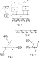
figure 1 is a scheme of the device for optimising the movement of automated-guided vehicles, and the like, according to the present invention; -
figure 2 is a schematic view of possible two-directional routes for vehicles able to be managed through the method and the device for optimising the movement of automated-guided vehicles, according to the present invention. -
figure 3 is a schematic view of possible routes for vehicles able to be managed through the method and the device for optimising the movement of automated-guided vehicles, according to the present invention; and -
figure 4 is a schematic view of a sequence of segments to be travelled by two automated-guided vehicles, according to the present invention. - According to what has been illustrated in
figure 1 , the device for optimising the movement of automated-guided vehicles, wholly indicated withreference numeral 20, essentially comprises: - a
traffic management module 21 that manages the movement of some automated-guided vehicles AGV1, AGV2, AGV3, ..., AGVn; - a
reassignment module 24 of the missions of the automated-guided vehicles - i.e. for assigning the pick-up and delivery missions of the articles, for each vehicle, according to an optimising criterion - connected so as to communicate with thetraffic management module 21 and with the automated-guided vehicles AGVn, remembering that here the term optimal or optimising has the meaning of finding the best allowed solution with respect to the constraints imposed; - a
solving module 25 that is connected to and is in communication with thetraffic management module 21. - In some cases, the
optimisation device 20 can optionally comprise a higher-level supervisor module 23, hence indicated infigure 1 with a broken line. This supervisor module is in turn in communication with thetraffic management module 21 and with thesolving module 25. - Among the tasks of the supervisor module is the preliminary selection, in the medium term, of the routes, the advance allocation of routes to particular AGVs through optimising criteria, the sequencing of the loading and unloading missions so as to "pre-plan" the traffic.
- The
optimisation device 20 also comprises amemory 26 in which the plan of the warehouse - the so-called layout - or the area in which the vehicles AGV must move is represented, and from this layout of the warehouse it is then possible to obtain the connection graph that is located in the respectiveconnection graph module 27, which comprises an outline of the possible routes for the vehicles AGV. The connection graph is then used by thetraffic management module 21 to move the vehicles AGV. - In greater detail, the
traffic management module 21 receives the data from theconnection graph module 27 and the overall state of the system, i.e. the current position of the vehicles AGV, the missions that the vehicles must carry out, etc. - The
traffic management module 21 then calculates, for each AGV, a reduced connection graph, i.e. a graph that is formed from the general graph portion that the AGV can actually reach in a predetermined number of steps, hereafter indicated as time frame T. - This information, i.e. the overall state of the system and the reduced connection graph for each vehicle AGV, are then passed to the
solving module 25, which reprocesses it through an integer linear programming model, discussed hereafter, providing an optimised preliminary solution of the routes, in the form of a sequence of segments that each vehicle AGV must travel. - Since the preliminary solution provided by the
solving module 25 used an approximate model (discussed hereafter), thetraffic management module 21 must check the actual compatibility of the solution and thus check the assignments of the route segments to the vehicles in question. - In the example illustrated in
figure 4 , thesolving module 25 provides a sequence of segments "b" and "c" for the vehicle AGV1, whereas for the vehicle AGV2, it provides the sequence of segments "a" and "d". - It should be noted that such a solution can be carried out by the
solving module 25 since in the first step the vehicle AGV1 travels along the segment "b" and the vehicle AGV2 travels along the segment "a" and in the next step the vehicle AGV1 travels along the segment "c" and the vehicle AGV2 travels along the segment "d". - From the example indicated above it can be seen that the solution proposed above is compatible because, despite the crossing of route segments "a" and "c", these sections are travelled by the two vehicles AGV1 and AGV2 at different times.
- In detail, the
device 21 according to the present invention carries out the following activities: - it periodically checks the current position of the automated-guided vehicles in the different segments of the route, and each time a given vehicle AGVn changes its current segment, it checks the possibility of assigning the other segments to the other vehicles AGV1, AGV2, ... AGVn-1;
- it assigns a route segment to a certain automated-guided vehicle in the time period "t1", only if all of the route segments relating to the previous time period "t1-1" have been assigned to all the other vehicles, this rule being necessary to prevent the solution to be applied from satisfying the priority of passage indicated in the solution of the model;
- it composes a message with the segments to be assigned to each vehicle and sends it to the
traffic manager 21 that sorts it for the vehicles AGV involved. - Each time the solving
module 25 has processed a solution for moving the AGVs, thereassignment module 24 is recalled, which reassigns the AGVs - among those that can be reassigned - to activate the missions. - The vehicles AGV that can be reassigned are those that are not connected, by this term meaning the vehicles AGV engaged in a mission from the start moment of picking up a load of products up to the end of unloading of the load.
- During this time period, the load of products relating to a mission is physically connected to the relative vehicle AGV, and therefore it is not possible to assign such a mission to be carried out to other vehicles.
- It should also be noted that the
reassignment module 24 assigns the missions to the vehicles AGV in a mathematically optimised manner, i.e. minimising the sum of the nominal time relative to the shortest routes (i.e. the routes that allow the destination to be reached in the shortest time possible without considering possible deviations needed to avoid "jams") that the vehicles must carry out to move from the final node of the segment assigned up to that moment to the respective mission destination nodes. - In greater detail, the
reassignment module 24 reassigns the missions to the vehicles AGV, minimising the sum of the travel times of the vehicles themselves until the respective mission objective has been reached. - The objective function to be minimised is the sum of all the nominal travel times from the final point of each vehicle AGV, meaning the point in which the given segments end up to that moment.
- The aforementioned sum of all the distances is calculated in advance based on the predetermined routes, for each pair of nodes, through an algorithm for calculating the minimum routes (like for example the known Dijkstra algorithm).
- In practice, each node of the connection graph has an associated matrix that comprises all of the minimum nominal times towards the other nodes, calculated with the calculation algorithm of the minimum routes.
- The solving
module 25 generates an integer linear programming model using the data received from thetraffic management module 21. - In particular, the solving
module 25 comprises a memory in which the elements of the integer linear programming that define the system are recorded: variables, coefficients of the objective function, matrix of the constraints; the solvingmodule 25 also comprises an actual linear solver. - As already stated, the solving module uses an approximate linear model, in which:
- a) the travel time of each segment of the graph is considered to be known and fixed, i.e. each segment is always travelled with the same time. This is the most important approximation, which is certainly not satisfied by the current graphs in which very short segments and very long segments coexist. However, from simulation carried out, we have been able to find that, if the ratio between the length of the longer and shorter segments of the route is between 1.5 and 2, then the optimal sequence of travel steps is almost always the same. In reality, of course, the travel times of the segments can vary, and this is the reason for the compatibility check that is carried out at each step by the traffic management module;
- b) in the current embodiment of the invention, the release points are ignored, i.e. the point in a certain segment that must be passed by a vehicle before the previous node can be declared free; this hypothesis derives from the consideration that the use of the information on the release points can be considered excessive if compared to the time needed for communication/decision.
- Good planning ensures that the vehicles can move fluidly even though they are very close together. In practice, however, if the programming times are too short, they can be in different non-ideal situations. Of course, the release points are considered by the
traffic management module 21 during the assignment of segments. - It should be noted that the solution proposed by the solver cannot be applied, or is practically unachievable, only in the case of a closed loop of segments (
figure 3 ), in which each segment is blocked while the destination node is still occupied, but this is a situation that is almost impossible to carry out, since each vehicle is drawn towards its destination and it is difficult for the vehicles to be routed in a closed loop of segments. However, in order to avoid most of these situations, an additional incompatibility is added for each loop of 2 segments (n1, n2) and (n2, n1), leaving the possibility that higher order loops (three AGVs for three segments, four AGVs for four segments, and so on) occur, which can happen with negligible probability. - Going back to the module of the
connection graph 27 and as already stated above, in such a module the calculation of the minimum distances between each pair of nodes of the connection graph is carried out. Such a calculation is carried out, for example, through the Dijkstra algorithm, then a matrix is associated to each node of the graph that comprises all the minimum distances towards the other nodes. In the module of theconnection graph 27 also the incompatibilities of the routes for the vehicles AGV identified are verified, in advance, through the analysis of the graph. - For example, referring to the scheme illustrated in
figure 2 of a two-directional corridor, let us consider the segments (1,2) and (4,3): such segments do not block one another. However, if such segments are assigned one after the other to two vehicles AGV, the two vehicles will be forced to stop, i.e. a so-called deadlock is produced. - Moreover, the pair of segments (1,2) and (5,4) can also have the same problem: after assignment to two different vehicles AGV, the vehicle on the
node 4. can only travel along the segment (4,3), which is incompatible with the segment (1,2). As a result the segments (1,2) and (5,4) also have a so-called static incompatibility, which will be discussed hereafter. - The scheme of
figure 3 represents another example of incompatibility with 3 segments. - If a first vehicle AGV1 is routed on the segment (8,1), a second vehicle AGV2 is routed on the segment (7,2) and a third vehicle AGV3 is routed on the segment (9,3), there will be a deadlock condition.
- Indeed, the segment (1,4) for the first vehicle is blocked by the
node 2, the segment (2,5) for the second vehicle is blocked by thenode 3 and the segment (3,6) for the third vehicle is blocked by thenode 1. - The consequence is that the set of incompatible segments, defined by the string Sincomp = {(8,1), (7,2), (9,3)}, can be added to a list of segments that are not wished to be assigned to different vehicles consecutively. This set of segments will be considered in the model solved by the solving
module 25 through some constraints, known as "static incompatibility" constraints. - The situations of incompatible segments must be identified in advance in the structure of the graph, i.e. it is necessary to find all of the segments that must not be occupied simultaneously.
- In order to carry out this analysis it is possible to proceed by automatically checking the connection graph, i.e. through a suitable algorithm the details of which will be provided hereafter.
- It is also possible to carry out experimental testing sessions with the vehicles AGV finding, through simulation, the block or deadlock situations.
- Once the groups of incompatible segments that cause the blocking of a simulation have been identified, they are stored in a list and the solving
module 25 will apply suitable constraints to prevent the AGVs from being located on such groups of incompatible segments. - One particular case to be considered is that of two-directional segments. In general, it is better to avoid a vehicle AGV continuing to move back and forth on two-directional segments: this situation is comparable to the above indicated livelocks and, even when it does not take the system into an irresolvable condition, it causes a loss of time and, therefore, a drop in performance.
- Therefore, in the step of checking for incompatibility, just the movements of the AGVs that do not go back to a segment already seen are considered.
- However, there is one particular case in which it is wished for the vehicle AGV to go back into the same route segment.
- This case happens when a vehicle AGV enters into the loading area that was assigned to it, and it is clear that afterwards the vehicle will have to come out again from such an area, and this is the sole case in which a vehicle AGV is permitted to go back into the same route segment.
- Of course, if we do not consider this particular case, all of the possible sets of last segments to a mission node could have been classified as incompatible.
- Finally, the last case to be considered consists of the definition of so-called no-stop nodes. For theoretical and technological reasons, and in order to limit the solving time, the integer linear programming models cannot have a very high number of variables.
- For this reason, as seen, we consider a time frame of T time periods - or in an equivalent way T assignable segments, at most, to each vehicle.
- It is advantageous for the last segment assigned to a vehicle not to be such that its final node hinders, in the sense of incompatibility between movements, other AGVs manoeuvring near to the respective mission nodes. In this way the AGVs leaving their missions are ensured a route towards the next destination, without needing to wait for the entering vehicles to free up the segment.
- For this reason, for each mission node all of the nodes that do not have to be the final point of the last segment assigned to an AGV are determined a priori: such nodes are called no-stop nodes, since the AGVs are not permitted to make stops on such nodes. The algorithm for the identification of the no-stop nodes will be described hereafter.
- Finally, in some situations it may be advantageous to plan, at least in an approximate manner, route sections significantly in advance: for example, to decide the order of entry of the AGVs in an area of the plant. The task of planning in advance, "at an another level", the travel along these corridors can be carried out by the high-
level module 23, which, in any case, delegates to thesolver 25 object of this invention the task of solving the "local" problem of selecting the approach route to the corridor, of assigning segments to all the vehicles present in order to avoid deadlock. - As known, linear optimisation models specify the relationship between the decision variables and the parameters, calculating a representative measurement to be optimised and other resulting variables.
- The constraints, on the other hand, set limitations to the space of the possible decisions; the admissible values of the decision variables are determined through a series of equality or inequality constraints.
- Therefore, it is necessary to select the values of the decision variables so as to satisfy the inequality constraints and at the same time maximise or minimise the result.
- The integer linear programming model that is used in the solving
module 25 is defined a mathematical formulation described hereafter. Concerning this, with regard to the decision variables and the constraints, the problem is described by the binary decision variables
- Therefore, the definition of decision variable is

- With this notation, the variable

- As far as the objective function is concerned, it is an integer linear programming function defined as

- There are then the following constraints


- Constraint (1.2) indicates that each vehicle must occupy one, and only one node, at each time moment;
- Constraint (1.3) imposes that no more than one vehicle can be in a node at each time moment;
- Constraint (1.4) imposes the structure of the graph. Indeed, since V(n) is the set of nodes able to be reached through a single route segment coming out from the node n, the constraint (1.4) ensures that at time t + 1 the AGV v is on a node able to be reached by one of the nodes n' ∈ v(n), with a single route segment.
- Further constraints take into consideration the physical dimensions of the AGVs and the incompatibility between segments and nodes described earlier.
- Such constraints are called blocking rules.
- The first constraint expresses the situation "the segment (n 1, n 2) blocks the segment (n 3 , n 4)" and can be expressed in the linear form

- The second constraint expresses the situation "the node k blocks the segment (n 1, n 2)"

- A further "static constraint makes all the relative positions of a set of vehicles that would lead the system to a deadlock unpermitted, i.e. in the condition in which no AGV is free to move without bumping into another. Before describing such a constraint, it is important to observe that the set of unpermitted positions is determined a priori, once for all, from the graph and from the segment/segment and node/segment incompatibility rules already discussed through an ad hoc algorithm that will be described hereafter. The constraints of this type are called static constraints since they are calculated a priori and do not depend on the type of mission of the AGVs or on the relative disconnected or connected state.
- The principle expressed by this constraint ensures that, given a set Ss of a number s incompatible segments, for example the set S 2 of two segments that are incompatible with each other, the set S 3 of three segments that are incompatible with each other, and so on, any subset of s vehicles are not assigned sets of segments in Ss .
- It should be noted that the number s of incompatible segments correspond to the number s of vehicles taken into consideration.
- For example, two vehicles are not assigned two segments that correspond to an element of S 2, three vehicles are not assigned three segments that correspond to one of the elements in S 3, and so on. In particular, in the case of incompatibility between the two segments (n1, n2), which could be travelled by AGV1 (v 1), and (n3, n4), which could be travelled by AGV2 (v 2), the constraint becomes

- It should be noted that the second member is a constant that expresses the number of variables present at the first member, decreased by 1.
- In the case in which k vehicles respectively travel along the arcs (ns
i , ndi ), i = 1,2, ...k , and they can block one another, whereas k - 1 vehicles would still have the possibility of moving along the respective routes, the constraint takes the form
i and ndi represent the initial and final node of the i-th AGV i, i = 1,2, ... , k. The constraint (1.8) is written for each pair of s and for each pair of time moments ti = 0, ..., T - 1. - A second type of constraint considered manages the no-stop nodes, which impose that n x cannot be assigned to a vehicle, for example the vehicle v 2, as the last node, if another vehicle, for example v 1, has already travelled along a particular segment, for example (ns, nd ).
- In this case, the constraint expressed in analytical form becomes

- It should be noted that both the static constraints and the no-stop-node constraints introduce tests of the type "the last segment travelled by the vehicle...".
- Since it is not possible to known a priori in which time slot the last segment will be assigned, such constraints require the generation of T constraints, one for each time period from 0 to T-1.
- Finally, it should be noted that the nodes considered in the optimisation step are only those that can be reached by a certain vehicle v within the time period T, starting from the node occupied at the time period 0.
- As far as the objective function to be minimised is concerned, the aforementioned coefficients f(n, v, t) are different for vehicles with or without a mission.
- For vehicles with missions, the term f(n, v, t) is:


missions 24 redirects it towards a position, called home position. The node closest to the AGV among those belonging to a predefined set (stored in the module 27) and not occupied by other AGVs is selected as the home position. - As far as the AGVs without mission are concerned, the coefficients in objective function are equal to 1 for the nodes on which the vehicles are located, and equal to 2 for all of the other nodes. With this choice, such vehicles "tend" to stay still, unless they are on the route of a vehicle AGV with a mission, or are incompatible with it. In this case, the increased total cost caused by the movement of such vehicles (i.e. 2 for each node travelled) is negligible with respect to the reduction in total cost due to the approach of the vehicles with mission to the respective objectives.
- The same principle can be easily applied to the case in which the AGVs without a mission are directed towards the so-called home positions. In this case, as soon as a vehicle AGV reaches the home position n, the cost of the virtual segment (n, n), which represents the behaviour "stay on the same node for a time period", is set at 1, while the cost of the segment (n, m), with n ≠ m, is set at 2; with these selections, also in this case a vehicle without a mission stays in the initial position unless it constitutes an obstacle for the other vehicles with missions assigned;
as an additional rule, for each vehicle without a mission, we then consider a "repulsion force" from the mission nodes of other AGVs, so as to reduce the interference between the vehicles with and without a mission. The additional cost by which the coefficients f(n, v, t) of the vehicle v is multiplied for all the nodes n that are, or can be, the mission of other AGVs is given by the formula
- The following exceptions also affect the definition of the cost function:
- if n is a mission node, and if the vehicle v does not have a mission in the node n, then it is f(n, v, t) = MAX_INT, with MAX_INT being the largest whole number able to be represented by a calculator. This selection prevents a vehicle from being directed towards a mission node different from its own;
- if from the last change in mission an AGV has been on the same node for TSDeadlock time periods (potential deadlock), or it has passed by the same node more than TS_Count times (potential livelock) then the cost becomes

- In order to identify the sets of incompatible segments that define the static constraints it is possible to proceed in two ways:
- by evaluating the blocking rules that prevent collisions between vehicles and manually determining which are groups of incompatible segments; this process allows almost all the pairs of incompatible segments to be identified;
- by carrying out a simulation and storing as incompatible all the groups of segments on which deadlock situations occur; this method makes it possible to identify the groups of more than two segments that are incompatible and possibly the pairs that were missed during the manual evaluation, according to the previous point.
- In this paragraph we will describe the algorithm used to identify the so-called NO-STOP NODES. Regarding this, it is important to observe that each segment s is characterised by a different set of NO-STOP NODES, hereafter indicated with NSNs.
- The algorithm foresees that:
- 1. S is the set of all the segments that connect all of the nodes of the possible routes;
- 2. for each segment s in S, all the nodes that are incompatible with all those after s are NO-STOP NODES;
- 3. if S is not empty
- a. Having extracted a segment s in S, and removed from S, add to NSNs all of the nodes that are NO-STOP NODES for all those after s, excluding the inverse segment (j, i) of s = (i, j), if it is not the only one;
- b. If the set NSNs has changed, then add to S, if not already present, all of the segments that precede s;
- 4. add to NSNs all the nodes that are incompatible with those after s ;
- 5. for each segment s = (i, j) remove the NO-STOP NODES n if
- a. n coincides with i, or with j, or it is a mission node;
- b. The minimum route between i and n added to the threshold parameter NSN_Threshold is lower than the minimum distance between n and j ;
- c. the minimum distance between j and n is more than a certain distance
- In this algorithm, since
points - the first limitation mechanism 5a removes the origin and destination nodes of s and the mission nodes;
- the second limitation mechanism 5b implements a heuristic rule aimed at eliminating from the set NSNs some nodes that, whilst
satisfying point 4 of the algorithm, i.e. they are "incompatible" with the successors s, they are not true NO-STOP NODES because there are no arcs that can be backward routed up to s, a condition expressed by the inequality between the distances; - the third limitation mechanism 5c limits the set NSNs to nodes within a certain distance (NSN_RangeMeters) from s.
- The invention, thus conceived, allows important technical advantages to be obtained.
- An important technical advantage is that the method for optimising the movement of automated-guided vehicles, and the like, allows the routes that the vehicles must follow between stations to carry out the assigned missions to be optimised, reducing the time necessary for the transportation of articles, and ensuring that jams cannot be created along the routes, even in the case of a high number of automated-guided vehicles. The method for optimising the movement of automated-guided vehicles, and the like, also allows a saving, not just of time, but also of money. It has thus been seen how the invention achieves the proposed purposes.
- The present invention has been described according to preferred embodiments, but equivalent variants can be devised without departing from the scope of protection offered by the following claims.
Claims (15)
- Device (20) for optimising the movement of automated-guided vehicles, comprising a traffic management module (21) to manage the movement of some automated-guided vehicles (AGV1, AGV2, AGV3 ..., AGVn) over routes of a graph defined by segments and nodes for connecting the segments, said automated-guided vehicles being indicated by a number v, wherein v indicates the current vehicle, with v = 1, 2, ..., V, said nodes being indicated by a number n, wherein n indicates the current node, with n = 1, 2, ..., N, according to time periods t, and wherein t = 1, 2, ..., T is the current time period, wherein the device (20) comprises a solving module (25) connected to and in communication with the traffic management module (21), the device being characterised by said solving module (25) executing an optimising solution using the following integer linear programming function:


 constraint (1.2) indicates that each vehicle must occupy one, and only one node, at each time moment;constraint (1.3) imposes that no more than one vehicle can be in a node at each time moment;constraint (1.4) imposes the structure of the graph,V(n) being the set of nodes able to be reached through a single route segment coming out from the node n.
 - Device (20) for optimising the movement of automated-guided vehicles according to claim 1, comprising a constraint that expresses the situation in which the segment (n 1, n 2) blocks the segment (n 3, n 4) and it is expressed in the linear form

- Device (20) for optimising the movement of automated-guided vehicles according to claim 1 or 2, comprising a constraint that expresses the situation in which the node k blocks the segment (n 1, n 2) and is expressed in the linear form

- Device (20) for optimising the movement of automated-guided vehicles according to any one of the previous claims, comprising a constraint that ensures that, taking two incompatible segments, the whole of the last segments assigned to each of the vehicles is not equal to one of the elements of S, and it is expressed in the linear form

- Device (20) for optimising the movement of automated-guided vehicles according to any one of the previous claims, comprising a constraint that expresses the situation in which s vehicles can block one another, whereas s - 1 vehicles would still have the possibility of moving along the respective routes, and it is expressed in the linear form

i and ndi represent the initial and final node of the i-th AGV i, i = 1,2, ..., k. The constraint (1.8) is written for each pair set of s and for each pair of time moments ti = 0, ..., T - 1. - Device (20) for optimising the movement of automated-guided vehicles according to any one of the previous claims, comprising a constraint that imposes that n x cannot be assigned as last node to a vehicle, for example the vehicle v 2, if another vehicle, for example v 1, has already travelled along a particular segment, for example (ns, nd ), and it is expressed in the linear form

- Device (20) for optimising the movement of automated-guided vehicles according to any one of the previous claims, wherein the function f(n,v,t) is determined in the following way:


if a certain vehicle (AGVn) does not have a mission, the traffic management module (21) redirects it towards an initial position, called home position n, set in advance, or it leaves it on the last node reached; as soon as the vehicle (AGVn) reaches the home position n, either it stays on the last node reached, the cost of the virtual segment (n, n), which represents the behaviour of staying on the same node for a time period, is set at 1, whereas the cost of the segment (n, m), with n ≠ m, is set at 2; in this way a certain vehicle (AGVn) stays in the initial position if it does not constitute an obstacle to the other vehicles with assigned missions. - Device (20) for optimising the movement of automated-guided vehicles according to any one of the previous claims, comprising a rule so that for each vehicle (AGVn) without a mission, a repulsion force is considered from the mission nodes of other vehicles (AGV1, AGV2, AGV3 ..., AGVn-1, ..., AGVn+1, ...), so as to reduce the interference between the vehicles with a mission and vehicles without a mission; the additional cost by which the coefficient f(n, v, t) of a node without a mission is multiplied is given by the formula

- Device (20) for optimising the movement of automated-guided vehicles according to any one of the previous claims, comprising a rule so that for each vehicle (AGVn) with a mission, the additional cost by which the coefficient f(n, v, t) is multiplied is:


- Device (20) for optimising the movement of automated-guided vehicles according to any one of the previous claims, comprising the rule:if from the last change of mission an AGV has been on the same node for TSDeadlock time periods (potential deadlock), or it has passed by the same node more than IS_Count times (potential livelock) then the cost becomes
 where MalusForDeadlock is a design parameter.
 - Device (20) for optimising the movement of automated-guided vehicles according to any one of the previous claims, comprising a rule through which for each mission node all of the nodes that must not be the final point of the last segment assigned to a certain AGV are determined, such nodes being defined as no-stop nodes, the aforementioned rule comprises:each segment s is characterised by a different set of NO-STOP NODES, indicated with NSNs ;S is the set of all of the segments that connect all of the nodes of the possible routes;for each segment s in S, all of the nodes that are incompatible with all of the successors of s are NO-STOP NODES;if S is not emptyhaving extracted a segment s in S, and removed from S, add to NSNs all of the nodes that are NO-STOP NODES for all the successors of s, excluding the inverse segment (j, i) of s = (i, j), if it is not the only one;if the set NSNs has changed, then add to S, if not already present, all of the segments that precede s;add to NUNs all of the nodes incompatible with the successors of s;for each segment s = (i, j) remove the n-th NO-STOP NODES (n) ifn coincides with i, or with j, or it is a mission node;the minimum path between i and n added to the threshold parameter (NSN_Threshold) is lower than the minimum distance between n and j;the minimum distance between j and n is greater than a certain distance (NSN_RangeMeters).
- Device (20) for optimising the movement of automated-guided vehicles according to any one of the previous claims, comprising a reassignment module (24) of the missions of the automated-guided vehicles, such a reassignment module (24) being connected so as to communicate with the traffic management module (21) and with the automated-guided vehicles (AGV1, AGV2, AGV3, ..., AGVn).
- Device (20) for optimising the movement of automated-guided vehicles according to any one of the previous claims, comprising connection graph module (27), which comprises a plan of the possible routes for the vehicles (AGV1, AGV2, AGV3 ..., AGVn).
- Device (20) for optimising the movement of automated-guided vehicles according to any one of the previous claims, wherein said solving module (25) provides an approximate solution of the assignments of the routes to said vehicles (AGV1, AGV2, AGV3, ..., AGVn), and wherein said traffic management module (21) must verify the actual compatibility of the solution and then check the assignments of the route segments to said vehicles (AGV1, AGV2, AGV3 ..., AGVn).
- Method for optimising the movement of automated-guided vehicles (AGV1, AGV2, ..., AGVn), comprising the steps of:managing the movement of some automated-guided vehicles (AGV1, AGV2, AGV3 ..., AGVn) on routes of a graph defined by segments and nodes connecting the segments, said automated-guided vehicles being indicated by a number v, wherein v indicates the current vehicle, with v = 1, 2, ..., V, said nodes being indicated by a number n, wherein n indicates the current node, with n = 1, 2, ..., N, according to time periods t, and wherein t = 1, 2, ..., T is the current time period, characterised in that it comprises an optimising solution step of said movement of some automated-guided vehicles obtained using the following integer linear programming function:
 said function representing the objective function, and the coefficients f(n,v,t) indicate the minimum distance between the node n on which the vehicle v could be located at time t, with respect to the mission node of the vehicle v, and wherein
 with the following constraints

 which have the following meaning:constraint (1.2) indicates that each vehicle must occupy one, and only one node, at each time moment;constraint (1.3) imposes that no more than one vehicle can be in a node at each time moment;constraint (1.4) imposes the structure of the graph,V(n) being the set of nodes able to be reached through a single route segment coming out from the node n.
Applications Claiming Priority (2)
| Application Number | Priority Date | Filing Date | Title |
|---|---|---|---|
| IT000178A ITVR20130178A1 (en) | 2013-07-26 | 2013-07-26 | DEVICE AND METHOD FOR THE OPTIMIZATION OF THE HANDLING OF AUTOMATIC DRIVEN VEHICLES, AND SIMILAR |
| PCT/IB2014/063349 WO2015011661A2 (en) | 2013-07-26 | 2014-07-23 | Device and method for optimising the movement of automated-guided vehicles, and the like |
Publications (2)
| Publication Number | Publication Date |
|---|---|
| EP3025206A2 EP3025206A2 (en) | 2016-06-01 |
| EP3025206B1 true EP3025206B1 (en) | 2017-09-06 |
Family
ID=49263408
Family Applications (1)
| Application Number | Title | Priority Date | Filing Date |
|---|---|---|---|
| EP14771380.4A Active EP3025206B1 (en) | 2013-07-26 | 2014-07-23 | Device and method for optimising the movement of automated-guided vehicles |
Country Status (4)
| Country | Link |
|---|---|
| EP (1) | EP3025206B1 (en) |
| ES (1) | ES2644703T3 (en) |
| IT (1) | ITVR20130178A1 (en) |
| WO (1) | WO2015011661A2 (en) |
Cited By (3)
| Publication number | Priority date | Publication date | Assignee | Title |
|---|---|---|---|---|
| DE102020214005A1 (en) | 2020-11-08 | 2022-05-12 | Fraunhofer-Gesellschaft zur Förderung der angewandten Forschung eingetragener Verein | Method for efficient route planning of vehicles in a sorting system |
| EP4664230A1 (en) * | 2024-06-10 | 2025-12-17 | Kollmorgen Automation AB | Method and system for identifying travel blocking situations |
| US12633215B2 (en) | 2023-05-12 | 2026-05-19 | Volvo Autonomous Solutions AB | Traffic planning method for a vehicle fleet |
Families Citing this family (9)
| Publication number | Priority date | Publication date | Assignee | Title |
|---|---|---|---|---|
| DE102016009255B4 (en) * | 2016-07-29 | 2023-01-26 | Kuka Roboter Gmbh | Coordination of paths of multiple moving machines |
| CN107067779A (en) * | 2016-11-30 | 2017-08-18 | 英华达(上海)科技有限公司 | Automated guided vehicle traffic control system and method |
| CN110347178B (en) * | 2019-06-21 | 2021-11-05 | 东华大学 | A UAV track planning method based on spatial geometric features |
| US12124261B2 (en) * | 2020-11-20 | 2024-10-22 | Rapyuta Robotics Co., Ltd. | Systems and methods for optimizing route plans in an operating environment |
| CN112783211A (en) * | 2021-01-06 | 2021-05-11 | 中国人民解放军陆军装甲兵学院 | Subdivision theory-based unmanned aerial vehicle and ground armor formation cooperative control method |
| EP4095640B1 (en) * | 2021-05-26 | 2025-01-22 | Volvo Autonomous Solutions AB | Method and system for controlling a plurality of vehicles, in particular autonomous vehicles |
| EP4113241B1 (en) * | 2021-07-01 | 2023-08-16 | Volvo Autonomous Solutions AB | Method and system for traffic control of a plurality of vehicles, in particular autonomous vehicles |
| CN115981264B (en) * | 2023-02-28 | 2025-06-24 | 上海交通大学 | AGV scheduling and quantity combined optimization method considering conflict |
| CN117094629B (en) * | 2023-09-18 | 2024-05-10 | 兰州交通大学 | Dangerous goods full-load distribution path optimization and vehicle dispatching method |
-
2013
- 2013-07-26 IT IT000178A patent/ITVR20130178A1/en unknown
-
2014
- 2014-07-23 EP EP14771380.4A patent/EP3025206B1/en active Active
- 2014-07-23 ES ES14771380.4T patent/ES2644703T3/en active Active
- 2014-07-23 WO PCT/IB2014/063349 patent/WO2015011661A2/en not_active Ceased
Non-Patent Citations (1)
| Title |
|---|
| None * |
Cited By (3)
| Publication number | Priority date | Publication date | Assignee | Title |
|---|---|---|---|---|
| DE102020214005A1 (en) | 2020-11-08 | 2022-05-12 | Fraunhofer-Gesellschaft zur Förderung der angewandten Forschung eingetragener Verein | Method for efficient route planning of vehicles in a sorting system |
| US12633215B2 (en) | 2023-05-12 | 2026-05-19 | Volvo Autonomous Solutions AB | Traffic planning method for a vehicle fleet |
| EP4664230A1 (en) * | 2024-06-10 | 2025-12-17 | Kollmorgen Automation AB | Method and system for identifying travel blocking situations |
Also Published As
| Publication number | Publication date |
|---|---|
| ITVR20130178A1 (en) | 2015-01-27 |
| WO2015011661A2 (en) | 2015-01-29 |
| ES2644703T3 (en) | 2017-11-30 |
| WO2015011661A3 (en) | 2015-07-02 |
| EP3025206A2 (en) | 2016-06-01 |
| WO2015011661A9 (en) | 2015-08-13 |
Similar Documents
| Publication | Publication Date | Title |
|---|---|---|
| WO2015011661A9 (en) | Device and method for optimising the movement of automated-guided vehicles | |
| CN118863472B (en) | An AGV forklift collaborative scheduling method and system for smart warehouse management | |
| Ribino et al. | Agent-based simulation study for improving logistic warehouse performance | |
| CN110182527B (en) | Warehouse-in and warehouse-out control method and conveying system for shelf array | |
| EP3152712B1 (en) | Methods, systems and apparatus for controlling movement of transporting devices | |
| Skinner et al. | Optimisation for job scheduling at automated container terminals using genetic algorithm | |
| US20230075128A1 (en) | Column generation methods and systems for routing and scheduling in robotic and vehicular applications | |
| CN113359702B (en) | Intelligent warehouse AGV operation optimization scheduling method based on water wave optimization-tabu search | |
| CN110182528B (en) | Warehouse-in and warehouse-out control method and conveying system for shelf array | |
| Thanos et al. | Dispatch and conflict-free routing of capacitated vehicles with storage stack allocation | |
| Hamzheei et al. | An ant colony-based algorithm for finding the shortest bidirectional path for automated guided vehicles in a block layout | |
| Fazlollahtabar et al. | Mathematical model for deadlock resolution in multiple AGV scheduling and routing network: a case study | |
| US20240174446A1 (en) | Managing a warehouse having robots of different types | |
| CN116719329B (en) | Path planning method, system, equipment and storage medium | |
| Hsueh | A simulation study of a bi-directional load-exchangeable automated guided vehicle system | |
| CN116339257A (en) | AGV multi-vehicle dispatching system and related dispatching method | |
| Solichudin et al. | Conflict-free dynamic route multi-AGV using dijkstra floyd-warshall hybrid algorithm with time windows | |
| Rathi et al. | Dynamic prioritization for conflict-free path planning of multi-robot systems | |
| Vivaldini et al. | Automatic routing of forklift robots in warehouse applications | |
| Tus et al. | Metaheuristics for the two-dimensional container pre-marshalling problem | |
| Li | Task Assignment and Path Planning for Autonomous Mobile Robots in Stochastic Warehouse Systems | |
| Stavrou et al. | Assignment and coordination of autonomous robots in container loading terminals | |
| Akiyama et al. | A multi-commodity flow model for guide path layout design of AGV systems | |
| Fazlollahtabar et al. | A Monte Carlo simulation to estimate TAGV production time in a stochastic flexible automated manufacturing system: a case study | |
| Truong et al. | Optimizing automated storage and retrieval algorithm in cold warehouse by combining dynamic routing and continuous cluster method |
Legal Events
| Date | Code | Title | Description |
|---|---|---|---|
| PUAI | Public reference made under article 153(3) epc to a published international application that has entered the european phase |
Free format text: ORIGINAL CODE: 0009012 |
|
| 17P | Request for examination filed |
Effective date: 20151127 |
|
| AK | Designated contracting states |
Kind code of ref document: A2 Designated state(s): AL AT BE BG CH CY CZ DE DK EE ES FI FR GB GR HR HU IE IS IT LI LT LU LV MC MK MT NL NO PL PT RO RS SE SI SK SM TR |
|
| AX | Request for extension of the european patent |
Extension state: BA ME |
|
| DAX | Request for extension of the european patent (deleted) | ||
| GRAP | Despatch of communication of intention to grant a patent |
Free format text: ORIGINAL CODE: EPIDOSNIGR1 |
|
| INTG | Intention to grant announced |
Effective date: 20170223 |
|
| GRAS | Grant fee paid |
Free format text: ORIGINAL CODE: EPIDOSNIGR3 |
|
| GRAA | (expected) grant |
Free format text: ORIGINAL CODE: 0009210 |
|
| AK | Designated contracting states |
Kind code of ref document: B1 Designated state(s): AL AT BE BG CH CY CZ DE DK EE ES FI FR GB GR HR HU IE IS IT LI LT LU LV MC MK MT NL NO PL PT RO RS SE SI SK SM TR |
|
| REG | Reference to a national code |
Ref country code: GB Ref legal event code: FG4D |
|
| REG | Reference to a national code |
Ref country code: CH Ref legal event code: EP Ref country code: AT Ref legal event code: REF Ref document number: 926523 Country of ref document: AT Kind code of ref document: T Effective date: 20170915 |
|
| REG | Reference to a national code |
Ref country code: IE Ref legal event code: FG4D |
|
| REG | Reference to a national code |
Ref country code: DE Ref legal event code: R096 Ref document number: 602014014279 Country of ref document: DE |
|
| REG | Reference to a national code |
Ref country code: NL Ref legal event code: FP |
|
| REG | Reference to a national code |
Ref country code: ES Ref legal event code: FG2A Ref document number: 2644703 Country of ref document: ES Kind code of ref document: T3 Effective date: 20171130 |
|
| REG | Reference to a national code |
Ref country code: LT Ref legal event code: MG4D |
|
| PG25 | Lapsed in a contracting state [announced via postgrant information from national office to epo] |
Ref country code: LT Free format text: LAPSE BECAUSE OF FAILURE TO SUBMIT A TRANSLATION OF THE DESCRIPTION OR TO PAY THE FEE WITHIN THE PRESCRIBED TIME-LIMIT Effective date: 20170906 Ref country code: NO Free format text: LAPSE BECAUSE OF FAILURE TO SUBMIT A TRANSLATION OF THE DESCRIPTION OR TO PAY THE FEE WITHIN THE PRESCRIBED TIME-LIMIT Effective date: 20171206 Ref country code: SE Free format text: LAPSE BECAUSE OF FAILURE TO SUBMIT A TRANSLATION OF THE DESCRIPTION OR TO PAY THE FEE WITHIN THE PRESCRIBED TIME-LIMIT Effective date: 20170906 Ref country code: HR Free format text: LAPSE BECAUSE OF FAILURE TO SUBMIT A TRANSLATION OF THE DESCRIPTION OR TO PAY THE FEE WITHIN THE PRESCRIBED TIME-LIMIT Effective date: 20170906 Ref country code: FI Free format text: LAPSE BECAUSE OF FAILURE TO SUBMIT A TRANSLATION OF THE DESCRIPTION OR TO PAY THE FEE WITHIN THE PRESCRIBED TIME-LIMIT Effective date: 20170906 |
|
| REG | Reference to a national code |
Ref country code: AT Ref legal event code: MK05 Ref document number: 926523 Country of ref document: AT Kind code of ref document: T Effective date: 20170906 |
|
| PG25 | Lapsed in a contracting state [announced via postgrant information from national office to epo] |
Ref country code: LV Free format text: LAPSE BECAUSE OF FAILURE TO SUBMIT A TRANSLATION OF THE DESCRIPTION OR TO PAY THE FEE WITHIN THE PRESCRIBED TIME-LIMIT Effective date: 20170906 Ref country code: RS Free format text: LAPSE BECAUSE OF FAILURE TO SUBMIT A TRANSLATION OF THE DESCRIPTION OR TO PAY THE FEE WITHIN THE PRESCRIBED TIME-LIMIT Effective date: 20170906 Ref country code: BG Free format text: LAPSE BECAUSE OF FAILURE TO SUBMIT A TRANSLATION OF THE DESCRIPTION OR TO PAY THE FEE WITHIN THE PRESCRIBED TIME-LIMIT Effective date: 20171206 Ref country code: GR Free format text: LAPSE BECAUSE OF FAILURE TO SUBMIT A TRANSLATION OF THE DESCRIPTION OR TO PAY THE FEE WITHIN THE PRESCRIBED TIME-LIMIT Effective date: 20171207 |
|
| PG25 | Lapsed in a contracting state [announced via postgrant information from national office to epo] |
Ref country code: PL Free format text: LAPSE BECAUSE OF FAILURE TO SUBMIT A TRANSLATION OF THE DESCRIPTION OR TO PAY THE FEE WITHIN THE PRESCRIBED TIME-LIMIT Effective date: 20170906 Ref country code: RO Free format text: LAPSE BECAUSE OF FAILURE TO SUBMIT A TRANSLATION OF THE DESCRIPTION OR TO PAY THE FEE WITHIN THE PRESCRIBED TIME-LIMIT Effective date: 20170906 Ref country code: CZ Free format text: LAPSE BECAUSE OF FAILURE TO SUBMIT A TRANSLATION OF THE DESCRIPTION OR TO PAY THE FEE WITHIN THE PRESCRIBED TIME-LIMIT Effective date: 20170906 |
|
| PG25 | Lapsed in a contracting state [announced via postgrant information from national office to epo] |
Ref country code: SM Free format text: LAPSE BECAUSE OF FAILURE TO SUBMIT A TRANSLATION OF THE DESCRIPTION OR TO PAY THE FEE WITHIN THE PRESCRIBED TIME-LIMIT Effective date: 20170906 Ref country code: EE Free format text: LAPSE BECAUSE OF FAILURE TO SUBMIT A TRANSLATION OF THE DESCRIPTION OR TO PAY THE FEE WITHIN THE PRESCRIBED TIME-LIMIT Effective date: 20170906 Ref country code: AT Free format text: LAPSE BECAUSE OF FAILURE TO SUBMIT A TRANSLATION OF THE DESCRIPTION OR TO PAY THE FEE WITHIN THE PRESCRIBED TIME-LIMIT Effective date: 20170906 Ref country code: IS Free format text: LAPSE BECAUSE OF FAILURE TO SUBMIT A TRANSLATION OF THE DESCRIPTION OR TO PAY THE FEE WITHIN THE PRESCRIBED TIME-LIMIT Effective date: 20180106 Ref country code: SK Free format text: LAPSE BECAUSE OF FAILURE TO SUBMIT A TRANSLATION OF THE DESCRIPTION OR TO PAY THE FEE WITHIN THE PRESCRIBED TIME-LIMIT Effective date: 20170906 |
|
| REG | Reference to a national code |
Ref country code: DE Ref legal event code: R097 Ref document number: 602014014279 Country of ref document: DE |
|
| PLBE | No opposition filed within time limit |
Free format text: ORIGINAL CODE: 0009261 |
|
| STAA | Information on the status of an ep patent application or granted ep patent |
Free format text: STATUS: NO OPPOSITION FILED WITHIN TIME LIMIT |
|
| REG | Reference to a national code |
Ref country code: FR Ref legal event code: PLFP Year of fee payment: 5 |
|
| PG25 | Lapsed in a contracting state [announced via postgrant information from national office to epo] |
Ref country code: DK Free format text: LAPSE BECAUSE OF FAILURE TO SUBMIT A TRANSLATION OF THE DESCRIPTION OR TO PAY THE FEE WITHIN THE PRESCRIBED TIME-LIMIT Effective date: 20170906 |
|
| 26N | No opposition filed |
Effective date: 20180607 |
|
| PG25 | Lapsed in a contracting state [announced via postgrant information from national office to epo] |
Ref country code: SI Free format text: LAPSE BECAUSE OF FAILURE TO SUBMIT A TRANSLATION OF THE DESCRIPTION OR TO PAY THE FEE WITHIN THE PRESCRIBED TIME-LIMIT Effective date: 20170906 |
|
| REG | Reference to a national code |
Ref country code: CH Ref legal event code: PL |
|
| PG25 | Lapsed in a contracting state [announced via postgrant information from national office to epo] |
Ref country code: LU Free format text: LAPSE BECAUSE OF NON-PAYMENT OF DUE FEES Effective date: 20180723 Ref country code: MC Free format text: LAPSE BECAUSE OF FAILURE TO SUBMIT A TRANSLATION OF THE DESCRIPTION OR TO PAY THE FEE WITHIN THE PRESCRIBED TIME-LIMIT Effective date: 20170906 |
|
| REG | Reference to a national code |
Ref country code: BE Ref legal event code: MM Effective date: 20180731 |
|
| REG | Reference to a national code |
Ref country code: IE Ref legal event code: MM4A |
|
| PG25 | Lapsed in a contracting state [announced via postgrant information from national office to epo] |
Ref country code: LI Free format text: LAPSE BECAUSE OF NON-PAYMENT OF DUE FEES Effective date: 20180731 Ref country code: CH Free format text: LAPSE BECAUSE OF NON-PAYMENT OF DUE FEES Effective date: 20180731 Ref country code: IE Free format text: LAPSE BECAUSE OF NON-PAYMENT OF DUE FEES Effective date: 20180723 |
|
| PG25 | Lapsed in a contracting state [announced via postgrant information from national office to epo] |
Ref country code: BE Free format text: LAPSE BECAUSE OF NON-PAYMENT OF DUE FEES Effective date: 20180731 |
|
| PG25 | Lapsed in a contracting state [announced via postgrant information from national office to epo] |
Ref country code: MT Free format text: LAPSE BECAUSE OF NON-PAYMENT OF DUE FEES Effective date: 20180723 |
|
| PG25 | Lapsed in a contracting state [announced via postgrant information from national office to epo] |
Ref country code: TR Free format text: LAPSE BECAUSE OF FAILURE TO SUBMIT A TRANSLATION OF THE DESCRIPTION OR TO PAY THE FEE WITHIN THE PRESCRIBED TIME-LIMIT Effective date: 20170906 |
|
| PG25 | Lapsed in a contracting state [announced via postgrant information from national office to epo] |
Ref country code: PT Free format text: LAPSE BECAUSE OF FAILURE TO SUBMIT A TRANSLATION OF THE DESCRIPTION OR TO PAY THE FEE WITHIN THE PRESCRIBED TIME-LIMIT Effective date: 20170906 |
|
| PG25 | Lapsed in a contracting state [announced via postgrant information from national office to epo] |
Ref country code: CY Free format text: LAPSE BECAUSE OF FAILURE TO SUBMIT A TRANSLATION OF THE DESCRIPTION OR TO PAY THE FEE WITHIN THE PRESCRIBED TIME-LIMIT Effective date: 20170906 Ref country code: MK Free format text: LAPSE BECAUSE OF NON-PAYMENT OF DUE FEES Effective date: 20170906 Ref country code: HU Free format text: LAPSE BECAUSE OF FAILURE TO SUBMIT A TRANSLATION OF THE DESCRIPTION OR TO PAY THE FEE WITHIN THE PRESCRIBED TIME-LIMIT; INVALID AB INITIO Effective date: 20140723 |
|
| PG25 | Lapsed in a contracting state [announced via postgrant information from national office to epo] |
Ref country code: AL Free format text: LAPSE BECAUSE OF FAILURE TO SUBMIT A TRANSLATION OF THE DESCRIPTION OR TO PAY THE FEE WITHIN THE PRESCRIBED TIME-LIMIT Effective date: 20170906 |
|
| REG | Reference to a national code |
Ref country code: DE Ref legal event code: R081 Ref document number: 602014014279 Country of ref document: DE Owner name: E80 GROUP S.P.A., IT Free format text: FORMER OWNER: ELETTRIC 80 S.P.A., VIANO, REGGIO EMILIA, IT |
|
| REG | Reference to a national code |
Ref country code: NL Ref legal event code: HC Owner name: E80 GROUP S.P.A.; IT Free format text: DETAILS ASSIGNMENT: CHANGE OF OWNER(S), CHANGE OF OWNER(S) NAME; FORMER OWNER NAME: ELETTRIC 80 S.P.A. Effective date: 20220809 |
|
| REG | Reference to a national code |
Ref country code: ES Ref legal event code: PC2A Owner name: E80 GROUP S.P.A. Effective date: 20221104 |
|
| P01 | Opt-out of the competence of the unified patent court (upc) registered |
Effective date: 20230515 |
|
| REG | Reference to a national code |
Ref country code: DE Ref legal event code: R079 Ref document number: 602014014279 Country of ref document: DE Free format text: PREVIOUS MAIN CLASS: G05D0001020000 Ipc: G05D0001430000 |
|
| PGFP | Annual fee paid to national office [announced via postgrant information from national office to epo] |
Ref country code: NL Payment date: 20250726 Year of fee payment: 12 |
|
| PGFP | Annual fee paid to national office [announced via postgrant information from national office to epo] |
Ref country code: ES Payment date: 20250801 Year of fee payment: 12 |
|
| PGFP | Annual fee paid to national office [announced via postgrant information from national office to epo] |
Ref country code: DE Payment date: 20250729 Year of fee payment: 12 |
|
| PGFP | Annual fee paid to national office [announced via postgrant information from national office to epo] |
Ref country code: IT Payment date: 20250723 Year of fee payment: 12 |
|
| PGFP | Annual fee paid to national office [announced via postgrant information from national office to epo] |
Ref country code: GB Payment date: 20250728 Year of fee payment: 12 |
|
| PGFP | Annual fee paid to national office [announced via postgrant information from national office to epo] |
Ref country code: FR Payment date: 20250725 Year of fee payment: 12 |