EP3023755A2 - Optical impedance modulation for fuel quantity measurement - Google Patents
Optical impedance modulation for fuel quantity measurement Download PDFInfo
- Publication number
- EP3023755A2 EP3023755A2 EP15195345.2A EP15195345A EP3023755A2 EP 3023755 A2 EP3023755 A2 EP 3023755A2 EP 15195345 A EP15195345 A EP 15195345A EP 3023755 A2 EP3023755 A2 EP 3023755A2
- Authority
- EP
- European Patent Office
- Prior art keywords
- optical
- optical fiber
- light guide
- fuel
- light
- Prior art date
- Legal status (The legal status is an assumption and is not a legal conclusion. Google has not performed a legal analysis and makes no representation as to the accuracy of the status listed.)
- Granted
Links
Images


Classifications
-
- G—PHYSICS
- G01—MEASURING; TESTING
- G01C—MEASURING DISTANCES, LEVELS OR BEARINGS; SURVEYING; NAVIGATION; GYROSCOPIC INSTRUMENTS; PHOTOGRAMMETRY OR VIDEOGRAMMETRY
- G01C5/00—Measuring height; Measuring distances transverse to line of sight; Levelling between separated points; Surveyors' levels
-
- G—PHYSICS
- G01—MEASURING; TESTING
- G01F—MEASURING VOLUME, VOLUME FLOW, MASS FLOW OR LIQUID LEVEL; METERING BY VOLUME
- G01F23/00—Indicating or measuring liquid level or level of fluent solid material, e.g. indicating in terms of volume or indicating by means of an alarm
- G01F23/22—Indicating or measuring liquid level or level of fluent solid material, e.g. indicating in terms of volume or indicating by means of an alarm by measuring physical variables, other than linear dimensions, pressure or weight, dependent on the level to be measured, e.g. by difference of heat transfer of steam or water
- G01F23/28—Indicating or measuring liquid level or level of fluent solid material, e.g. indicating in terms of volume or indicating by means of an alarm by measuring physical variables, other than linear dimensions, pressure or weight, dependent on the level to be measured, e.g. by difference of heat transfer of steam or water by measuring the variations of parameters of electromagnetic or acoustic waves applied directly to the liquid or fluent solid material
- G01F23/284—Electromagnetic waves
- G01F23/292—Light, e.g. infrared or ultraviolet
-
- B—PERFORMING OPERATIONS; TRANSPORTING
- B64—AIRCRAFT; AVIATION; COSMONAUTICS
- B64D—EQUIPMENT FOR FITTING IN OR TO AIRCRAFT; FLIGHT SUITS; PARACHUTES; ARRANGEMENT OR MOUNTING OF POWER PLANTS OR PROPULSION TRANSMISSIONS IN AIRCRAFT
- B64D37/00—Arrangements in connection with fuel supply for power plant
- B64D37/005—Accessories not provided for in the groups B64D37/02 - B64D37/28
-
- G—PHYSICS
- G01—MEASURING; TESTING
- G01C—MEASURING DISTANCES, LEVELS OR BEARINGS; SURVEYING; NAVIGATION; GYROSCOPIC INSTRUMENTS; PHOTOGRAMMETRY OR VIDEOGRAMMETRY
- G01C9/00—Measuring inclination, e.g. by clinometers, by levels
-
- G—PHYSICS
- G01—MEASURING; TESTING
- G01C—MEASURING DISTANCES, LEVELS OR BEARINGS; SURVEYING; NAVIGATION; GYROSCOPIC INSTRUMENTS; PHOTOGRAMMETRY OR VIDEOGRAMMETRY
- G01C9/00—Measuring inclination, e.g. by clinometers, by levels
- G01C9/005—Measuring inclination, e.g. by clinometers, by levels specially adapted for use in aircraft
-
- G—PHYSICS
- G01—MEASURING; TESTING
- G01C—MEASURING DISTANCES, LEVELS OR BEARINGS; SURVEYING; NAVIGATION; GYROSCOPIC INSTRUMENTS; PHOTOGRAMMETRY OR VIDEOGRAMMETRY
- G01C9/00—Measuring inclination, e.g. by clinometers, by levels
- G01C9/02—Details
-
- G—PHYSICS
- G01—MEASURING; TESTING
- G01F—MEASURING VOLUME, VOLUME FLOW, MASS FLOW OR LIQUID LEVEL; METERING BY VOLUME
- G01F22/00—Methods or apparatus for measuring volume of fluids or fluent solid material, not otherwise provided for
-
- Y—GENERAL TAGGING OF NEW TECHNOLOGICAL DEVELOPMENTS; GENERAL TAGGING OF CROSS-SECTIONAL TECHNOLOGIES SPANNING OVER SEVERAL SECTIONS OF THE IPC; TECHNICAL SUBJECTS COVERED BY FORMER USPC CROSS-REFERENCE ART COLLECTIONS [XRACs] AND DIGESTS
- Y02—TECHNOLOGIES OR APPLICATIONS FOR MITIGATION OR ADAPTATION AGAINST CLIMATE CHANGE
- Y02T—CLIMATE CHANGE MITIGATION TECHNOLOGIES RELATED TO TRANSPORTATION
- Y02T50/00—Aeronautics or air transport
- Y02T50/40—Weight reduction
Definitions
- This disclosure generally relates to systems and methods for measuring a level of liquid in a reservoir, such as a storage tank or other container. More particularly, this disclosure relates to systems and methods for liquid level measurement using an optical sensor.
- liquid-level sensors are commonly used in the fuel tanks of aircraft, automobiles, and trucks. Liquid-level sensors are also used to monitor liquid levels within storage tanks used for fuel dispensing, wastewater treatment, chemical storage, food processing, etc.
- transducers for measuring liquid level employ electricity.
- the electrical output of such transducers changes in response to a change in the liquid level being measured, and is typically in the form of a change in resistance, capacitance, current flow, magnetic field, frequency, and so on.
- These types of transducers may include variable capacitors or resistors, optical components, Hall Effect sensors, strain gauges, ultrasonic devices, and so on.
- the subject matter disclosed herein is directed to systems and methods that use an optical impedance sensor to eliminate electricity for measuring fuel quantity in fuel tanks.
- the optical impedance sensor comprises two optical fibers spaced apart inside a meniscus tube, one to transmit light along its length and the other to receive light along its length.
- the meniscus tube minimizes the sloshing of fuel level.
- the variable fuel level in the tank produces changes in the optical impedance between the two optical fibers, resulting in changes in the total light received by an optical detector.
- the optical impedance sensor may comprise different embodiments in which the detection apparatus shapes the light to be unidirectional (emitted and collected only on one side of the fiber) or omnidirectional (all directions).
- the optical fibers can be made of either glass or plastic with sufficient optical output along the entire length of the sensor.
- optical impedance sensors disclosed herein do not require any electricity. Nor does the sensor installation require that the optical fiber be in contact with the fuel inside the tank, thereby avoiding possible contaminant buildup.
- the optical impedance sensors are designed to simplify complex safety measures while maintaining accuracy and reducing cost, weight and volume as compared to existing electrical capacitance sensors.
- an optical impedance sensor comprising: a tube having an internal volume; a first light guide comprising a first optical fiber and a first tube which encases the first optical fiber, wherein the first tube comprises a first jacket having a longitudinal slot and a first lens disposed in the longitudinal slot of the first jacket and optically coupled to the first optical fiber, and the first optical fiber comprises a cladding having a non-uniform surface in an area bounded by the longitudinal slot of the first jacket; and a second light guide comprising a second optical fiber spaced apart from the first optical fiber, wherein the second optical fiber comprises a cladding having a non-uniform surface in an area confronting the longitudinal slot of the first jacket.
- the non-uniform cladding surface is designed to control the amount of light emitting/collecting along the length of the optical fiber.
- the second light guide further comprises a second tube which encases the second optical fiber, the second tube comprising a second jacket having a longitudinal slot and a second lens disposed in the longitudinal slot of the second jacket and optically coupled to the second optical fiber, wherein the longitudinal slots of the first and second jackets are arranged in mutual opposition so that at least some light emitted from the longitudinal slot of the first jacket will directly enter the longitudinal slot of the second jacket.
- the first and second optical fibers may be substantially parallel.
- the second optical fiber may be spirally wrapped around the first optical fiber. In some embodiments the second optical fiber may be spirally wrapped at a variable pitch. In some embodiments the first optical fiber may have variable side leakage.
- the first optical fiber may include a mirror disposed at a bottom end thereof. Additionally or alternatively, the second optical fiber may include a mirror disposed at a bottom end thereof.
- the second optical fiber may be a fluorescent fiber having a core containing fluorescing dopants.
- the optical impedance sensor further comprises a third light guide comprising a third optical fiber and a third tube which encases the third optical fiber, wherein the third tube comprises a third jacket having a longitudinal slot and a third lens disposed in the longitudinal slot of the third jacket and optically coupled to the third optical fiber, and the third optical fiber comprises a cladding having a non-uniform surface in an area bounded by the longitudinal slot of the third jacket.
- the first and third light guides may have non-overlapping or slightly overlapping longitudinal slots which both emit light toward different segments of the second light guide.
- a system for measuring a level of liquid in a reservoir comprising: a tube having an internal volume, the tube being disposed in the reservoir; an optical source for outputting light; an optical detector for converting impinging light into an electrical signal representing an optical power of the impinging light; a first light guide comprising a first optical fiber and a first tube which encases the first optical fiber, wherein the first tube comprises a first jacket having a longitudinal slot and a first lens disposed in the longitudinal slot of the first jacket and optically coupled to the first optical fiber, and the first optical fiber comprises a cladding and a core inside the cladding, the cladding of the first optical fiber having a non-uniform surface in an area bounded by the longitudinal slot of the first jacket, and the core of the first optical fiber being optically coupled to receive light from the optical source; and a second light guide comprising a second optical fiber spaced apart from the first optical fiber, wherein the second optical fiber comprises a cladding and
- the foregoing system may further comprise a computer system programmed to compute a level of liquid in the reservoir based on optical power data received from the optical detector.
- the optical source comprises a laser and the optical detector comprises a photodiode.
- the disclosed system can be used to measure the level of fuel in a fuel tank on an airplane.
- the second light guide further comprises a second tube which encases the second optical fiber, the second tube comprising a second jacket having a longitudinal slot and a second lens disposed in the longitudinal slot of the second jacket and optically coupled to the second optical fiber, wherein the longitudinal slots of the first and second jackets are arranged in mutual opposition so that at least some light emitted from the longitudinal slot of the first jacket will directly enter the longitudinal slot of the second jacket.
- the system further comprises a third light guide comprising a third optical fiber and a third tube which encases the third optical fiber, wherein the third tube comprises a third jacket having a longitudinal slot and a third lens disposed in the longitudinal slot of the third jacket and optically coupled to the third optical fiber, and the third optical fiber comprises a cladding having a non-uniform surface in an area bounded by the longitudinal slot of the third jacket.
- a further aspect is a light guide comprising: an optical fiber having an axis and a circumferential surface; a jacket having a longitudinal slot that extends parallel to the axis of the optical fiber, the jacket being in contact with the circumferential surface of the optical fiber except in an area of the longitudinal slot; and a lens disposed in the longitudinal slot of the jacket and interfaced with the circumferential surface of the optical fiber, wherein the optical fiber comprises a cladding having a non-uniform surface in an area bounded by the longitudinal slot of the jacket.
- the light guide may further comprise a curved reflective surface disposed between the optical fiber and the jacket.
- the jacket is made of a material which is not optically transparent or translucent.
- Yet another aspect of the subject matter disclosed herein is a method for measuring a level of fuel in a fuel tank having multiple compartments, comprising: (a) placing a first tube in a first compartment; (b) placing a first light guide inside the first tube with an orientation that will be generally perpendicular to a surface of the fuel when the first compartment is at least partially filled with fuel, wherein the first light guide comprises a first optical fiber that is encased to prevent wetting of the first optical fiber when the first light guide is immersed in the fuel; (c) placing a second light guide inside the first tube spaced apart from and generally parallel with the first light guide, wherein the second light guide comprises a second optical fiber that is encased to prevent wetting of the second optical fiber when the second light guide is immersed in the fuel; (d) emitting light along a length of the first light guide toward a length of the second light guide; (e) detecting the optical power output from the second light guide; and (f) determining a level of the fuel in the first compartment based on
- the step of determining the level of fuel comprises comparing the detected optical power with a database of calibrated fuel level versus optical power.
- the method may further comprise: (g) placing a second tube in a second compartment having a height less than a height of the first compartment; (h) placing a third light guide inside the second tube with an orientation that will be generally perpendicular to a surface of the fuel when the second compartment is at least partially filled with fuel, wherein the third light guide comprises a third optical fiber that is encased to prevent wetting of the third optical fiber when the third light guide is immersed in the fuel; (i) placing a fourth light guide inside the second tube spaced apart from and surrounding the third light guide, wherein the fourth light guide has a spiral shape and comprises a fourth optical fiber that is encased to prevent wetting of the fourth optical fiber when the fourth light guide is immersed in the fuel; (j) emitting light along a length of the third light guide toward a length of the fourth light guide; (k) detecting the optical power
- optical impedance sensors suitable for use in fuel tanks are disclosed and claimed below.
- FIG. 1 shows a liquid level sensor 50 comprising an inner aluminum tube 54 and an outer aluminum tube 54 surrounding and concentric with the inner aluminum tube 54.
- the generally horizontal nonlinear line spanning the liquid level sensor 50 represents a level of fuel, i.e., an interface between fuel and air. Some of the fuel occupies space between the aluminum tubes.
- the total electrical capacitance of liquid level sensor 50 changes with fuel level in a well-known manner (air and fuel have different dielectric constants).
- the arrows represent flow of electrical charges from the inner aluminum tube 54 toward the outer aluminum tube 52 under the influence of an electric field in the space between the aluminum tubes.
- This liquid level sensor can be used to detect the fuel level because the electrical current flowing out of the outer aluminum tube 52 changes in dependence on the height of the volume of fuel in the space between the aluminum tubes.
- FIG. 2 is a hybrid diagram representing a system for measuring a level of fuel in a reservoir in accordance with one embodiment of the optical impedance modulation concept disclosed herein.
- the system depicted in FIG. 2 comprises an optical impedance sensor 2 that detects the optical impedance of the fluid separating the transmitting and receiving optical fibers, obtaining optical power data that can be later used to determine the fuel level.
- optical impedance sensor 2 comprises: a transmitting optical fiber 4 optically coupled to an optical source 10 by means of an optical fiber 12; and a receiving optical fiber 6 optically coupled to an optical detector 14 by means of an optical fiber 16.
- the optical impedance sensor 2 further comprises a meniscus tube 8 that minimizes fuel sloshing in a fuel tank (not shown).
- the nonlinear line spanning the optical impedance sensor 2 in FIG. 2 represents a level of fuel.
- the transmitting and receiving optical fibers 4 and 6 are placed inside the meniscus tube in spaced-apart relationship (preferably the fibers are straight and parallel to each other). In cases where the fuel tank is incorporated in a wing of an airplane, the transmitting and receiving optical fibers 4 and 6 are preferably rigidly supported in a fixed spatial relationship to provide a separation distance which is optimized for optical received power versus ice slush particles that may form in the fuel tank.
- the meniscus tube 8, which extends to the floor of the fuel tank, has openings near that floor which allow fuel to flow into the volume of space bounded by the meniscus tube 8. The level of the fuel will be the same inside and outside the meniscus tube 8.
- the transmitting optical fiber 4 When pumped by the optical source 10, the transmitting optical fiber 4 emits light radially outward.
- the axial distribution of emitted light may be substantially constant along the length of transmitting optical fiber 4.
- a first portion of the light will pass through the fuel and illuminates a lower portion of the receiving optical fiber 6.
- a second portion of light emitted by transmitting optical fiber 4 will pass through the air and illuminate an upper portion of the receiving optical fiber 6.
- At least some of the light received by receiving optical fiber 6 is guided upwards and other light is guided downwards inside the core of receiving optical fiber 6.
- the light guided downwards may be reflected upwards from a mirror disposed at the bottom end of receiving optical fiber 6 (see the description of FIG. 4 below). The light guided upwards and exits the upper end of receiving optical fiber 6.
- the light output by receiving optical fiber 6 is transmitted to the optical detector 14, which converts impinging light into electrical current.
- This electrical current is conducted by a cable to a processing unit (not shown in FIG. 2 , but see FIG. 3 ).
- the processor analyzes the signal from the optical detector 14 and computes the height of the air/fuel interface.
- the arrows in FIG. 2 represent light (i.e., photons) propagating from the transmitting optical fiber 4 to the receiving optical fiber 6 during operation of optical source 10.
- the brightness (i.e., intensity) of the light produced by optical source 10 i.e., its optical power
- the optical impedance of the fuel in the volume of space between transmitting optical fiber 4 and receiving optical fiber 6 changes in dependence on the fuel level, due to the fact that air and fuel have different refractive indices.
- air has an index of refraction less than the index of refraction of fuel; that fuel has an index of refraction less than the index of refraction of cladding of an optical fiber; and that the cladding has an index of refraction less than the index of refraction of the core of the optical fiber.
- the refractive indices determine the amount of light that is reflected when reaching an interface.
- the optical power output by the receiving optical fiber 6 will monotonically increase as the liquid level falls.
- the optical impedance between transmitting optical fiber 4 and receiving optical fiber 6 will change. These changes in optical impedance in turn produce changes in the optical power (i.e., light intensity) output by the receiving optical fiber 6 to the optical detector 14.
- each optical fiber is a flexible, optically transparent or translucent fiber made of extruded glass or plastic. It can function as a waveguide or light pipe to transmit light between the two ends of the fiber.
- Optical fibers typically include a transparent or translucent core having a relatively higher index of refraction surrounded by a transparent or translucent cladding material having a relatively lower index of refraction. Light is kept in the core by total internal reflection. This causes the optical fiber to act as a waveguide.
- the cladding of the transmitting optical fiber 4 is modified (e.g., by roughening or notching the circumferential surface) to enable a controlled level of radial light output along the fiber's length.
- the cladding of transmitting optical fiber 4 may be treated to produce a non-uniform surface at least in an area bounded by a longitudinal slot in a jacket.
- the outer surface of the cladding may be roughened or notched at least in an area overlapped by a longitudinal slot in a jacket, thereby forming a side window, as will be described in more detail below with reference to FIGS. 5 and 6 .
- the cladding of the receiving optical fiber 6 may be modified in a similar manner to form a side window that faces toward the side window of the transmitting optical fiber 4 when the optical sensor is installed inside a fuel tank.
- the receiving optical fiber 6 can be a fluorescent fiber having a core containing fluorescing dopants, which can be activated by light from the transmitting optical fiber 4 impinging on the side window of the receiving optical fiber 6 and then entering the core of the receiving optical fiber 6.
- fluorescing dopants produce light which travels along the length of the receiving optical fiber 6 and is then output to the optical detector 14.
- the circumferential variation in the emitted light is preferably strongly peaked in a narrow angular range subtended by the side window formed by modification of the cladding of the transmitting optical fiber 4.
- this side window can be formed by modifying the cladding of the optical fibers (e.g., by notching, scratching or sanding) on only one side to more easily emit light with an angular spread that impinges on a corresponding side window formed by modification of the cladding of the receiving optical fiber 6.
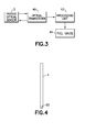
- FIG. 3 is a block diagram representing components of a system for measuring a level of fuel in a fuel tank in accordance with one embodiment.
- the system comprises a passive optical sensor 2 of the type depicted in FIG. 2 , an optical transceiver 40 which is optically coupled to the optical sensor 2, a processing unit 42 which is electrically coupled to the optical transceiver 40, and a fuel gauge 44 which indicates the fuel level graphically and/or alphanumeric ally.
- the optical sensor 2 is installed in a compartment of a fuel tank.
- optical transceiver 40 may comprise: an optical source in the form of a transmit integrated circuit connected to a transmit optical subassembly (comprising a laser or LED); and an optical detector in the form of a receive integrated circuit connected to a receive optical subassembly (comprising a photodiode).
- the fuel gauge 44 may take the form of a display device having a display processor programmed to a display screen to display the measurement results (e.g., the fuel level) graphically and/or alphanumeric ally.
- the magnitude of the signal output by the light detector of optical transceiver 40 increases monotonically with increasing intensity of light emitted from the end of receiving optical fiber 6.
- the processing unit 42 may be a dedicated microprocessor or a general-purpose computer, and may calculate the measured level (i.e., height) of the fuel by using a look-up table, a calibration curve, or by solving equations, as appropriate.
- the fuel gauge 44 may present information that identifies the amount of fuel present within the fuel tank based on optical power data received by the processing unit 42.
- the processing unit 42 may be a computer or part of a flight control system located on an aircraft. In identifying the amount of fuel present in an irregular-shaped fuel tank, the processing unit 42 may execute various routines to calculate the amount of fuel present based on optical power data received from multiple receiving optical fibers appropriately placed in various compartments of the fuel tank.
- the fuel information processing software may include routines which take into account the shape of the fuel tank to determine the amount of fuel remaining in the fuel tank.
- the fuel information processing software may further include routines for calibrating processes to form a baseline before a first use or to maintain accuracy of fuel readings. The readings provided by the processing unit 42 to the fuel gauge 44 may be integrated or averaged before presentation and may be provided at different time intervals.
- optical fibers are used to measure the level of fuel in a fuel tank.
- the same apparatus may be used to detect other liquids.
- the system described above may be used to detect the presence of water in a container or hydraulic fluids in a reservoir for a hydraulic system.
- the illustration of detecting fuel in a fuel tank is presented for purposes of illustration and not meant to limit the manner in which the system shown in FIG. 3 may be used.
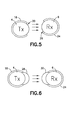
- a reflective mirror cap 22 may be attached to the bottom end of the transmitting optical fiber 4 to reflect light back through transmitting optical fiber 4 and to prevent light from being lost out the bottom end.
- a similar reflective cap may be attached to the bottom end of the receiving optical fiber 6 to reflect light back through the receiving optical fiber 6 toward the optical detector 14 (see FIG. 3 ).
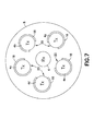
- FIG. 5 is a diagram representing a plan view of a pair of straight light guides of an optical sensor in accordance with an embodiment intended for use in the measurement of a level of a liquid that will not damage exposed optical fibers when the latter are immersed in the liquid.
- the transmitting light guide comprises: a transmitting optical fiber 4 having an axis and a circumferential surface; and a jacket 18 having a longitudinal slot 20 that extends parallel to the axis of the transmitting optical fiber 4 for the entire length of the latter.
- the longitudinal slot 20 overlaps a side window formed by a non-uniform surface on the cladding of the transmitting optical fiber 4.
- the jacket 18 is in contact with and covers the circumferential surface of the transmitting optical fiber 4 except in the area of longitudinal slot 20.
- the transmitting light guide may further comprise a curved reflective surface disposed between the transmitting optical fiber 4 and the jacket 18.
- the jacket 18 is made of a material which is not optically transparent or translucent, such as metal or polymeric material.
- the receiving light guide comprises: a receiving optical fiber 6 having an axis and a circumferential surface; and a jacket 24 having a longitudinal slot 26 that extends parallel to the axis of the receiving optical fiber 6 for the entire length of the latter.
- the longitudinal slot 26 overlaps the side window formed by a non-uniform surface on the cladding of the receiving optical fiber 6.
- the jacket 24 is in contact with the circumferential surface of the receiving optical fiber 6 except in an area of the longitudinal slot 26.
- the receiving light guide may further comprise a curved reflective surface disposed between the receiving optical fiber 6 and the jacket 24.
- the jacket 24 is made of a material which is not optically transparent or translucent, such as metal or polymeric material. In the case where the jacket 24 is made of polymeric material, jacket 24 can be formed by molding.
- the transmission optical fiber 4 and/or the receiving optical fiber 6 may have a circular, square or hexagonal cross section, with the molded jacket conforming to the shape of the optical fiber.
- the arrows in FIG. 5 represent light which has been emitted by transmitting optical fiber 4 through the side window formed in the cladding of the transmitting optical fiber 4 and is propagating through intervening fluid (e.g., liquid or air) toward the corresponding side window formed in the cladding of receiving optical fiber 6.
- intervening fluid e.g., liquid or air
- the exiting rays of light may be divergent, rather than collimated.
- FIG. 6 is a diagram representing a plan view of a pair of straight light guides of an optical sensor in accordance with an embodiment in which the liquid is not in direct contact with the transmitting and receiving optical fibers 4 and 6.
- the transmitting and receiving light guides further comprise respective lenses 28 and 30 formed (e.g., by molding) in the longitudinal slots of the respective jackets 18 and 24.
- the lenses 28 and 30 extend the full length of the longitudinal slots.
- lens 28 and jacket 18 encase the transmitting optical fiber 4, with lens 28 interfacing with the side window of transmitting optical fiber 4.
- lens 30 and jacket 24 encase the receiving optical fiber 6, with lens 30 interfacing with the side window of receiving optical fiber 6.
- the lenses 28 and 30 are made of epoxy.
- the arrows in FIG. 6 represent light which has been emitted by transmitting optical fiber 4 through the lens 28 and is propagating through intervening fluid (e.g., liquid or air) toward the lens 30 of the receiving light guide.
- the lens 28 may be designed so that exiting rays of light are directed in parallel toward the lens 30.
- the lens 30 may be designed so that impinging parallel rays of light are converged into the receiving optical fiber 6.
- the lenses have the effect of increasing the intensity of the light output by receiving optical fiber 6 for the same optical power being pumped into transmitting optical fiber 4, thereby enhancing the performance of the optical impedance sensor.
- the system may comprise a single transmitting optical fiber disposed parallel with one receiving optical fiber. If the optical power from one LED is inadequate, then the amount of light emitted can be increased in various ways.
- the system may comprise two or more transmitting optical fibers surrounding a centrally located receiving optical fiber. In this case the receiving optical fiber is collecting light from all sides, and each transmitting optical fiber has its own LED source.
- the signal-to-noise ratio of the optical impedance sensor is increased by employing multiple transmitting and/or receiving optical fibers.
- FIG. 7 is a diagram representing a plan view of an optical impedance sensor having a single centrally located receiving optical fiber 6 surrounded by a multiplicity of transmitting optical fibers 4a-4e inside a meniscus tube 8, each of transmitting optical fibers 4a-4e being partly encased in a respective jacket 18 having a longitudinal slot for sideways transmission of light toward the receiving optical fiber 6.
- the entire circumferential surface of the cladding of the receiving optical fiber 6 may be modified (e.g., by roughening, notching or sanding) to facilitate the entry of light into the receiving optical fiber 6.
- light emitted by transmitting optical fibers 4a-4e is directed toward the centrally located receiving optical fiber 6.
- the optical power output by receiving optical fiber 6 will be dependent on the level of liquid inside the meniscus tube 8.
- each surrounding transmitting optical fiber may concentrate its transmit power only in one segment of the fiber length.
- FIG. 8 is a diagram representing an isometric view of three transmitting optical fibers 32a-32c having non-overlapping or slightly overlapping emitting segments 34, 36 and 38 respectively (indicated by speckle patterns) for use in an optical impedance sensor having an extended length.
- Each of the emitting segments 34, 36 and 38 may be constructed with a respective side window and lens (as previously described) to emit light in a respective preferred direction, i.e., toward the side window of a centrally located receiving optical fiber (as seen in FIG. 7 ).
- the processing unit can be programmed to take into account the signals received from respective optical transceivers, which signals represent the optical power output by the respective receiving optical fibers.
- the system can be calibrated to determine the fuel level based on the optical power data. The height of the air/fuel interface in a fuel tank compartment can be readily determined from the optical power data in a well-known manner based on the attenuation losses due to light propagating through fuel rather than air.
- a wing of an airplane has a height that varies, especially in a spanwise direction.
- a fuel tank incorporated inside an aircraft wing has a height that varies.
- a wing fuel tank comprises a multiplicity of compartments. It would be desirable to provide different types of fuel level sensors which are suitable for installation in fuel tank compartments of different heights. For example, some compartments at the root of a wing may have a height of a few feet, while other compartments near the tip of the wing may have a height of a few inches.
- a tall sensor is typically installed in the fuel tank compartment at the root of the wing. Due to the longer length, there is enough difference in fuel height that enables 1% accuracy by simple use of a straight transmitting optical fiber in parallel with a receiving optical fiber. There is a controlled gap between the two fibers optimized for optical received power versus ice slush particles in the fuel tank.
- FIG. 9 is a diagram representing an isometric view of an optical impedance sensor having a spiral receiving optical fiber 46 for use in a reservoir having a small depth, such as at a tip of a wing fuel tank.
- the spiral receiving optical fiber 46 is placed inside a meniscus tube 8, wrapped around a central transmitting optical fiber 4, to increase optical power pickup per unit sensor length.
- variable pitch of a spiral receiving optical fiber or variable side leakage of a straight receiving optical fiber can be employed.
- a wing fuel tank system that uses electrical sensors can be retrofitted by substituting the optical sensors disclosed herein.
- Double shielded electrical wiring for the electrical sensors can be replaced with light and flexible plastic optical fiber, eliminating weight from the wiring and supporting brackets, and eliminating electromagnetic effects from lightning, shorting, fraying of electrical wiring.
- the passive optical sensors disclosed herein preferably use rugged plastic optical fiber. No shielding/bonding/grounding of signal wiring is required. There is no possibility of igniting fuel. As a result of using optical impedance sensors to measure fuel levels, the weight and cost of an airplane can be reduced.
- the term "computer system” should be construed broadly to encompass a system having at least one computer or processor, and which may have multiple computers or processors that communicate through a network or bus.
- the terms "computer” and “processor” both refer to devices having a processing unit (e.g., a central processing unit) and some form of memory (i.e., computer-readable medium) for storing a program which is readable by the processing unit.
Landscapes
- Physics & Mathematics (AREA)
- General Physics & Mathematics (AREA)
- Engineering & Computer Science (AREA)
- Electromagnetism (AREA)
- Fluid Mechanics (AREA)
- Radar, Positioning & Navigation (AREA)
- Remote Sensing (AREA)
- Aviation & Aerospace Engineering (AREA)
- Thermal Sciences (AREA)
- Measurement Of Levels Of Liquids Or Fluent Solid Materials (AREA)
- Level Indicators Using A Float (AREA)
Abstract
Description
- This disclosure generally relates to systems and methods for measuring a level of liquid in a reservoir, such as a storage tank or other container. More particularly, this disclosure relates to systems and methods for liquid level measurement using an optical sensor.
- A need to continuously measure the level of a liquid exists in many commercial and military applications. For example, liquid-level sensors are commonly used in the fuel tanks of aircraft, automobiles, and trucks. Liquid-level sensors are also used to monitor liquid levels within storage tanks used for fuel dispensing, wastewater treatment, chemical storage, food processing, etc.
- Many transducers for measuring liquid level employ electricity. The electrical output of such transducers changes in response to a change in the liquid level being measured, and is typically in the form of a change in resistance, capacitance, current flow, magnetic field, frequency, and so on. These types of transducers may include variable capacitors or resistors, optical components, Hall Effect sensors, strain gauges, ultrasonic devices, and so on.
- Currently most fuel sensors on aircraft use electricity. For example, existing electrical capacitance sensors require electrical wiring inside the tank, which in turn requires complex installations and protection measures to preclude a safety issue under certain electrical fault conditions. This electrical wiring requires careful shielding, bonding, and grounding to minimize stray capacitance and further requires periodic maintenance to ensure electrical contact integrity.
- There is ample room for improvements in systems and methods that can detect the level of liquid in a fuel tank without introducing electrical current into the fuel tank.
- The subject matter disclosed herein is directed to systems and methods that use an optical impedance sensor to eliminate electricity for measuring fuel quantity in fuel tanks. The optical impedance sensor comprises two optical fibers spaced apart inside a meniscus tube, one to transmit light along its length and the other to receive light along its length. The meniscus tube minimizes the sloshing of fuel level. The variable fuel level in the tank produces changes in the optical impedance between the two optical fibers, resulting in changes in the total light received by an optical detector.
- Depending on fuel tank height, which can range from a few inches to a few feet, the optical impedance sensor may comprise different embodiments in which the detection apparatus shapes the light to be unidirectional (emitted and collected only on one side of the fiber) or omnidirectional (all directions). The optical fibers can be made of either glass or plastic with sufficient optical output along the entire length of the sensor.
- The optical impedance sensors disclosed herein do not require any electricity. Nor does the sensor installation require that the optical fiber be in contact with the fuel inside the tank, thereby avoiding possible contaminant buildup. The optical impedance sensors are designed to simplify complex safety measures while maintaining accuracy and reducing cost, weight and volume as compared to existing electrical capacitance sensors.
- One aspect of the subject matter disclosed in detail below is an optical impedance sensor comprising: a tube having an internal volume; a first light guide comprising a first optical fiber and a first tube which encases the first optical fiber, wherein the first tube comprises a first jacket having a longitudinal slot and a first lens disposed in the longitudinal slot of the first jacket and optically coupled to the first optical fiber, and the first optical fiber comprises a cladding having a non-uniform surface in an area bounded by the longitudinal slot of the first jacket; and a second light guide comprising a second optical fiber spaced apart from the first optical fiber, wherein the second optical fiber comprises a cladding having a non-uniform surface in an area confronting the longitudinal slot of the first jacket. The non-uniform cladding surface is designed to control the amount of light emitting/collecting along the length of the optical fiber.
- In accordance with some embodiments, the second light guide further comprises a second tube which encases the second optical fiber, the second tube comprising a second jacket having a longitudinal slot and a second lens disposed in the longitudinal slot of the second jacket and optically coupled to the second optical fiber, wherein the longitudinal slots of the first and second jackets are arranged in mutual opposition so that at least some light emitted from the longitudinal slot of the first jacket will directly enter the longitudinal slot of the second jacket.
- In accordance with further embodiments, the first and second optical fibers may be substantially parallel.
- In accordance with other embodiments, the second optical fiber may be spirally wrapped around the first optical fiber. In some embodiments the second optical fiber may be spirally wrapped at a variable pitch. In some embodiments the first optical fiber may have variable side leakage.
- In accordance with yet other embodiments, the first optical fiber may include a mirror disposed at a bottom end thereof. Additionally or alternatively, the second optical fiber may include a mirror disposed at a bottom end thereof.
- In accordance with further embodiments, the second optical fiber may be a fluorescent fiber having a core containing fluorescing dopants.
- In accordance with still further embodiments, the optical impedance sensor further comprises a third light guide comprising a third optical fiber and a third tube which encases the third optical fiber, wherein the third tube comprises a third jacket having a longitudinal slot and a third lens disposed in the longitudinal slot of the third jacket and optically coupled to the third optical fiber, and the third optical fiber comprises a cladding having a non-uniform surface in an area bounded by the longitudinal slot of the third jacket. The first and third light guides may have non-overlapping or slightly overlapping longitudinal slots which both emit light toward different segments of the second light guide.
- Another aspect of the subject matter disclosed herein is a system for measuring a level of liquid in a reservoir, comprising: a tube having an internal volume, the tube being disposed in the reservoir; an optical source for outputting light; an optical detector for converting impinging light into an electrical signal representing an optical power of the impinging light; a first light guide comprising a first optical fiber and a first tube which encases the first optical fiber, wherein the first tube comprises a first jacket having a longitudinal slot and a first lens disposed in the longitudinal slot of the first jacket and optically coupled to the first optical fiber, and the first optical fiber comprises a cladding and a core inside the cladding, the cladding of the first optical fiber having a non-uniform surface in an area bounded by the longitudinal slot of the first jacket, and the core of the first optical fiber being optically coupled to receive light from the optical source; and a second light guide comprising a second optical fiber spaced apart from the first optical fiber, wherein the second optical fiber comprises a cladding and a core inside the cladding, the cladding of the second optical fiber having a non-uniform surface which receives light emitted by the first optical fiber through the longitudinal slot of the first jacket, and the core of the second optical fiber being optically coupled to output light to the optical detector. The foregoing system may further comprise a computer system programmed to compute a level of liquid in the reservoir based on optical power data received from the optical detector. In one implementation, the optical source comprises a laser and the optical detector comprises a photodiode. The disclosed system can be used to measure the level of fuel in a fuel tank on an airplane.
- In accordance with one embodiment of the system described in the preceding paragraph, the second light guide further comprises a second tube which encases the second optical fiber, the second tube comprising a second jacket having a longitudinal slot and a second lens disposed in the longitudinal slot of the second jacket and optically coupled to the second optical fiber, wherein the longitudinal slots of the first and second jackets are arranged in mutual opposition so that at least some light emitted from the longitudinal slot of the first jacket will directly enter the longitudinal slot of the second jacket.
- In accordance with another embodiment, the system further comprises a third light guide comprising a third optical fiber and a third tube which encases the third optical fiber, wherein the third tube comprises a third jacket having a longitudinal slot and a third lens disposed in the longitudinal slot of the third jacket and optically coupled to the third optical fiber, and the third optical fiber comprises a cladding having a non-uniform surface in an area bounded by the longitudinal slot of the third jacket.
- A further aspect is a light guide comprising: an optical fiber having an axis and a circumferential surface; a jacket having a longitudinal slot that extends parallel to the axis of the optical fiber, the jacket being in contact with the circumferential surface of the optical fiber except in an area of the longitudinal slot; and a lens disposed in the longitudinal slot of the jacket and interfaced with the circumferential surface of the optical fiber, wherein the optical fiber comprises a cladding having a non-uniform surface in an area bounded by the longitudinal slot of the jacket. The light guide may further comprise a curved reflective surface disposed between the optical fiber and the jacket. Preferably the jacket is made of a material which is not optically transparent or translucent.
- Yet another aspect of the subject matter disclosed herein is a method for measuring a level of fuel in a fuel tank having multiple compartments, comprising: (a) placing a first tube in a first compartment; (b) placing a first light guide inside the first tube with an orientation that will be generally perpendicular to a surface of the fuel when the first compartment is at least partially filled with fuel, wherein the first light guide comprises a first optical fiber that is encased to prevent wetting of the first optical fiber when the first light guide is immersed in the fuel; (c) placing a second light guide inside the first tube spaced apart from and generally parallel with the first light guide, wherein the second light guide comprises a second optical fiber that is encased to prevent wetting of the second optical fiber when the second light guide is immersed in the fuel; (d) emitting light along a length of the first light guide toward a length of the second light guide; (e) detecting the optical power output from the second light guide; and (f) determining a level of the fuel in the first compartment based on the detected optical power output from the second light guide. In accordance with some embodiments, the step of determining the level of fuel comprises comparing the detected optical power with a database of calibrated fuel level versus optical power. The method may further comprise: (g) placing a second tube in a second compartment having a height less than a height of the first compartment; (h) placing a third light guide inside the second tube with an orientation that will be generally perpendicular to a surface of the fuel when the second compartment is at least partially filled with fuel, wherein the third light guide comprises a third optical fiber that is encased to prevent wetting of the third optical fiber when the third light guide is immersed in the fuel; (i) placing a fourth light guide inside the second tube spaced apart from and surrounding the third light guide, wherein the fourth light guide has a spiral shape and comprises a fourth optical fiber that is encased to prevent wetting of the fourth optical fiber when the fourth light guide is immersed in the fuel; (j) emitting light along a length of the third light guide toward a length of the fourth light guide; (k) detecting the optical power output from the fourth light guide; and (l) determining a level of the fuel in the second compartment based on the detected optical power output from the fourth light guide. This methodology is well suited for measuring the level of fuel in a fuel tank that is incorporated in a wing of an aircraft.
- Other aspects of optical impedance sensors suitable for use in fuel tanks are disclosed and claimed below.
-
-
FIG. 1 is a diagram representing an isometric view of components of a typical sensor that modulates the electrical capacitance of a liquid. The nonlinear line spanning the sensor represents a level of liquid; the arrows represent flow of electrical charges. -
FIG. 2 is a hybrid diagram representing a system for measuring a level of a liquid that comprises an optical impedance sensor that modulates the optical impedance of the liquid. This hybrid diagram comprises a block diagram showing components of an optical transceiver and a diagram representing an isometric view of the optical impedance sensor. The nonlinear line spanning the sensor represents a level of liquid; the arrows represent photons propagating from one optical fiber to another optical fiber. -
FIG. 3 is a block diagram representing components of a system for measuring a level of liquid in a reservoir in accordance with one embodiment. -
FIG. 4 is a diagram representing an elevation view of an optical fiber having a mirror cap at one end for increasing the intensity of light inside the fiber. -
FIG. 5 is a diagram representing a plan view of a pair of optical fibers encased in respective jackets having mutually opposing longitudinal slots for sideways optical coupling of light (indicated by arrows) from the transmitting optical fiber to the receiving optical fiber. -
FIG. 6 is a diagram representing a plan view of a pair of optical fibers encased in respective jackets having mutually opposing longitudinal slots covered by respective lenses for sideways optical coupling of light (indicated by arrows) from the transmitting optical fiber to the receiving optical fiber. -
FIG. 7 is a diagram representing a plan view of an optical impedance sensor having a single centrally located receiving optical fiber surrounded by a multiplicity of transmitting optical fibers inside a meniscus tube, each transmitting optical fiber having a side window for emission of light toward the receiving optical fiber. -
FIG. 8 is a diagram representing an isometric view of three optical fibers having non-overlapping or slightly overlapping emitting segments (indicated by speckle patterns) for use in an optical impedance sensor having an extended length. -
FIG. 9 is a diagram representing an isometric view of an optical impedance sensor having a spiral receiving optical fiber for use in a reservoir having a small depth, such as at a tip of a wing fuel tank. - Reference will hereinafter be made to the drawings in which similar elements in different drawings bear the same reference numerals.
- Various embodiments of systems and methods for measurement of a level of liquid in a reservoir will now be described in detail for the purpose of illustration. At least some of the details disclosed below relate to optional features or aspects, which in some applications may be omitted without departing from the scope of the claims appended hereto.
-
FIG. 1 shows aliquid level sensor 50 comprising aninner aluminum tube 54 and anouter aluminum tube 54 surrounding and concentric with theinner aluminum tube 54. The generally horizontal nonlinear line spanning theliquid level sensor 50 represents a level of fuel, i.e., an interface between fuel and air. Some of the fuel occupies space between the aluminum tubes. The total electrical capacitance ofliquid level sensor 50 changes with fuel level in a well-known manner (air and fuel have different dielectric constants). The arrows represent flow of electrical charges from theinner aluminum tube 54 toward theouter aluminum tube 52 under the influence of an electric field in the space between the aluminum tubes. This liquid level sensor can be used to detect the fuel level because the electrical current flowing out of theouter aluminum tube 52 changes in dependence on the height of the volume of fuel in the space between the aluminum tubes. -
FIG. 2 is a hybrid diagram representing a system for measuring a level of fuel in a reservoir in accordance with one embodiment of the optical impedance modulation concept disclosed herein. The system depicted inFIG. 2 comprises anoptical impedance sensor 2 that detects the optical impedance of the fluid separating the transmitting and receiving optical fibers, obtaining optical power data that can be later used to determine the fuel level. In accordance with the embodiment shown inFIG. 2 ,optical impedance sensor 2 comprises: a transmittingoptical fiber 4 optically coupled to anoptical source 10 by means of anoptical fiber 12; and a receivingoptical fiber 6 optically coupled to anoptical detector 14 by means of anoptical fiber 16. Theoptical impedance sensor 2 further comprises ameniscus tube 8 that minimizes fuel sloshing in a fuel tank (not shown). The nonlinear line spanning theoptical impedance sensor 2 inFIG. 2 represents a level of fuel. The transmitting and receivingoptical fibers optical fibers meniscus tube 8, which extends to the floor of the fuel tank, has openings near that floor which allow fuel to flow into the volume of space bounded by themeniscus tube 8. The level of the fuel will be the same inside and outside themeniscus tube 8. - When pumped by the
optical source 10, the transmittingoptical fiber 4 emits light radially outward. The axial distribution of emitted light may be substantially constant along the length of transmittingoptical fiber 4. A first portion of the light will pass through the fuel and illuminates a lower portion of the receivingoptical fiber 6. A second portion of light emitted by transmittingoptical fiber 4 will pass through the air and illuminate an upper portion of the receivingoptical fiber 6. At least some of the light received by receivingoptical fiber 6 is guided upwards and other light is guided downwards inside the core of receivingoptical fiber 6. The light guided downwards may be reflected upwards from a mirror disposed at the bottom end of receiving optical fiber 6 (see the description ofFIG. 4 below). The light guided upwards and exits the upper end of receivingoptical fiber 6. The light output by receivingoptical fiber 6 is transmitted to theoptical detector 14, which converts impinging light into electrical current. This electrical current is conducted by a cable to a processing unit (not shown inFIG. 2 , but seeFIG. 3 ). The processor analyzes the signal from theoptical detector 14 and computes the height of the air/fuel interface. - The arrows in
FIG. 2 represent light (i.e., photons) propagating from the transmittingoptical fiber 4 to the receivingoptical fiber 6 during operation ofoptical source 10. During monitoring of the fuel level, the brightness (i.e., intensity) of the light produced by optical source 10 (i.e., its optical power) is preferably constant. As the fuel level varies, the optical impedance of the fuel in the volume of space between transmittingoptical fiber 4 and receivingoptical fiber 6 changes in dependence on the fuel level, due to the fact that air and fuel have different refractive indices. - It is well known that air has an index of refraction less than the index of refraction of fuel; that fuel has an index of refraction less than the index of refraction of cladding of an optical fiber; and that the cladding has an index of refraction less than the index of refraction of the core of the optical fiber. The refractive indices determine the amount of light that is reflected when reaching an interface.
- Since more optical power is lost (i.e., optical impedance is greater) in liquids than in air, the optical power output by the receiving
optical fiber 6 will monotonically increase as the liquid level falls. In other words, as the fuel level changes, the optical impedance between transmittingoptical fiber 4 and receivingoptical fiber 6 will change. These changes in optical impedance in turn produce changes in the optical power (i.e., light intensity) output by the receivingoptical fiber 6 to theoptical detector 14. - Although not depicted in
FIG. 2 , each optical fiber is a flexible, optically transparent or translucent fiber made of extruded glass or plastic. It can function as a waveguide or light pipe to transmit light between the two ends of the fiber. Optical fibers typically include a transparent or translucent core having a relatively higher index of refraction surrounded by a transparent or translucent cladding material having a relatively lower index of refraction. Light is kept in the core by total internal reflection. This causes the optical fiber to act as a waveguide. - In accordance with the embodiments disclosed herein, the cladding of the transmitting
optical fiber 4 is modified (e.g., by roughening or notching the circumferential surface) to enable a controlled level of radial light output along the fiber's length. More specifically, the cladding of transmittingoptical fiber 4 may be treated to produce a non-uniform surface at least in an area bounded by a longitudinal slot in a jacket. For example, the outer surface of the cladding may be roughened or notched at least in an area overlapped by a longitudinal slot in a jacket, thereby forming a side window, as will be described in more detail below with reference toFIGS. 5 and 6 . The cladding of the receivingoptical fiber 6 may be modified in a similar manner to form a side window that faces toward the side window of the transmittingoptical fiber 4 when the optical sensor is installed inside a fuel tank. - In addition or in the alternative, the receiving
optical fiber 6 can be a fluorescent fiber having a core containing fluorescing dopants, which can be activated by light from the transmittingoptical fiber 4 impinging on the side window of the receivingoptical fiber 6 and then entering the core of the receivingoptical fiber 6. (Fluorescence occurs when an orbital electron relaxes to its ground state by emitting a photon of light after being excited to a higher quantum state by some type of energy.) The fluorescing dopants produce light which travels along the length of the receivingoptical fiber 6 and is then output to theoptical detector 14. - At any given axial position along the length of the transmitting
optical fiber 4, the circumferential variation in the emitted light is preferably strongly peaked in a narrow angular range subtended by the side window formed by modification of the cladding of the transmittingoptical fiber 4. As previously mentioned, this side window can be formed by modifying the cladding of the optical fibers (e.g., by notching, scratching or sanding) on only one side to more easily emit light with an angular spread that impinges on a corresponding side window formed by modification of the cladding of the receivingoptical fiber 6. -
FIG. 3 is a block diagram representing components of a system for measuring a level of fuel in a fuel tank in accordance with one embodiment. The system comprises a passiveoptical sensor 2 of the type depicted inFIG. 2 , anoptical transceiver 40 which is optically coupled to theoptical sensor 2, aprocessing unit 42 which is electrically coupled to theoptical transceiver 40, and afuel gauge 44 which indicates the fuel level graphically and/or alphanumeric ally. In this example, theoptical sensor 2 is installed in a compartment of a fuel tank. The components ofoptical transceiver 40 may comprise: an optical source in the form of a transmit integrated circuit connected to a transmit optical subassembly (comprising a laser or LED); and an optical detector in the form of a receive integrated circuit connected to a receive optical subassembly (comprising a photodiode). Thefuel gauge 44 may take the form of a display device having a display processor programmed to a display screen to display the measurement results (e.g., the fuel level) graphically and/or alphanumeric ally. - The magnitude of the signal output by the light detector of
optical transceiver 40 increases monotonically with increasing intensity of light emitted from the end of receivingoptical fiber 6. Theprocessing unit 42 may be a dedicated microprocessor or a general-purpose computer, and may calculate the measured level (i.e., height) of the fuel by using a look-up table, a calibration curve, or by solving equations, as appropriate. Thefuel gauge 44 may present information that identifies the amount of fuel present within the fuel tank based on optical power data received by theprocessing unit 42. - The
processing unit 42 may be a computer or part of a flight control system located on an aircraft. In identifying the amount of fuel present in an irregular-shaped fuel tank, theprocessing unit 42 may execute various routines to calculate the amount of fuel present based on optical power data received from multiple receiving optical fibers appropriately placed in various compartments of the fuel tank. The fuel information processing software may include routines which take into account the shape of the fuel tank to determine the amount of fuel remaining in the fuel tank. The fuel information processing software may further include routines for calibrating processes to form a baseline before a first use or to maintain accuracy of fuel readings. The readings provided by theprocessing unit 42 to thefuel gauge 44 may be integrated or averaged before presentation and may be provided at different time intervals. - In the example shown in
FIG. 3 , optical fibers are used to measure the level of fuel in a fuel tank. In other embodiments, the same apparatus may be used to detect other liquids. For example, the system described above may be used to detect the presence of water in a container or hydraulic fluids in a reservoir for a hydraulic system. The illustration of detecting fuel in a fuel tank is presented for purposes of illustration and not meant to limit the manner in which the system shown inFIG. 3 may be used. - As shown in
FIG. 4 , areflective mirror cap 22 may be attached to the bottom end of the transmittingoptical fiber 4 to reflect light back through transmittingoptical fiber 4 and to prevent light from being lost out the bottom end. A similar reflective cap may be attached to the bottom end of the receivingoptical fiber 6 to reflect light back through the receivingoptical fiber 6 toward the optical detector 14 (seeFIG. 3 ). -
FIG. 5 is a diagram representing a plan view of a pair of straight light guides of an optical sensor in accordance with an embodiment intended for use in the measurement of a level of a liquid that will not damage exposed optical fibers when the latter are immersed in the liquid. The transmitting light guide comprises: a transmittingoptical fiber 4 having an axis and a circumferential surface; and ajacket 18 having alongitudinal slot 20 that extends parallel to the axis of the transmittingoptical fiber 4 for the entire length of the latter. Preferably thelongitudinal slot 20 overlaps a side window formed by a non-uniform surface on the cladding of the transmittingoptical fiber 4. Thejacket 18 is in contact with and covers the circumferential surface of the transmittingoptical fiber 4 except in the area oflongitudinal slot 20. The transmitting light guide may further comprise a curved reflective surface disposed between the transmittingoptical fiber 4 and thejacket 18. Preferably thejacket 18 is made of a material which is not optically transparent or translucent, such as metal or polymeric material. - Similarly, the receiving light guide comprises: a receiving
optical fiber 6 having an axis and a circumferential surface; and ajacket 24 having alongitudinal slot 26 that extends parallel to the axis of the receivingoptical fiber 6 for the entire length of the latter. Preferably thelongitudinal slot 26 overlaps the side window formed by a non-uniform surface on the cladding of the receivingoptical fiber 6. Thejacket 24 is in contact with the circumferential surface of the receivingoptical fiber 6 except in an area of thelongitudinal slot 26. The receiving light guide may further comprise a curved reflective surface disposed between the receivingoptical fiber 6 and thejacket 24. Preferably thejacket 24 is made of a material which is not optically transparent or translucent, such as metal or polymeric material. In the case where thejacket 24 is made of polymeric material,jacket 24 can be formed by molding. The transmissionoptical fiber 4 and/or the receivingoptical fiber 6 may have a circular, square or hexagonal cross section, with the molded jacket conforming to the shape of the optical fiber. - The arrows in
FIG. 5 represent light which has been emitted by transmittingoptical fiber 4 through the side window formed in the cladding of the transmittingoptical fiber 4 and is propagating through intervening fluid (e.g., liquid or air) toward the corresponding side window formed in the cladding of receivingoptical fiber 6. However, it should be appreciated that, in the absence of a focusing lens overlying the side window of the transmittingoptical fiber 4, the exiting rays of light may be divergent, rather than collimated. -
FIG. 6 is a diagram representing a plan view of a pair of straight light guides of an optical sensor in accordance with an embodiment in which the liquid is not in direct contact with the transmitting and receivingoptical fibers FIG. 5 is that the transmitting and receiving light guides further compriserespective lenses respective jackets lenses lens 28 andjacket 18 encase the transmittingoptical fiber 4, withlens 28 interfacing with the side window of transmittingoptical fiber 4. Similarly,lens 30 andjacket 24 encase the receivingoptical fiber 6, withlens 30 interfacing with the side window of receivingoptical fiber 6. Preferably thelenses - The arrows in
FIG. 6 represent light which has been emitted by transmittingoptical fiber 4 through thelens 28 and is propagating through intervening fluid (e.g., liquid or air) toward thelens 30 of the receiving light guide. Thelens 28 may be designed so that exiting rays of light are directed in parallel toward thelens 30. Thelens 30 may be designed so that impinging parallel rays of light are converged into the receivingoptical fiber 6. The lenses have the effect of increasing the intensity of the light output by receivingoptical fiber 6 for the same optical power being pumped into transmittingoptical fiber 4, thereby enhancing the performance of the optical impedance sensor. - If the optical power transmitted by a high-intensity LED is adequate, then the system may comprise a single transmitting optical fiber disposed parallel with one receiving optical fiber. If the optical power from one LED is inadequate, then the amount of light emitted can be increased in various ways. In some embodiments, the system may comprise two or more transmitting optical fibers surrounding a centrally located receiving optical fiber. In this case the receiving optical fiber is collecting light from all sides, and each transmitting optical fiber has its own LED source. In these alternative embodiments, the signal-to-noise ratio of the optical impedance sensor is increased by employing multiple transmitting and/or receiving optical fibers.
-
FIG. 7 is a diagram representing a plan view of an optical impedance sensor having a single centrally located receivingoptical fiber 6 surrounded by a multiplicity of transmittingoptical fibers 4a-4e inside ameniscus tube 8, each of transmittingoptical fibers 4a-4e being partly encased in arespective jacket 18 having a longitudinal slot for sideways transmission of light toward the receivingoptical fiber 6. In this case the entire circumferential surface of the cladding of the receivingoptical fiber 6 may be modified (e.g., by roughening, notching or sanding) to facilitate the entry of light into the receivingoptical fiber 6. During operation, light emitted by transmittingoptical fibers 4a-4e is directed toward the centrally located receivingoptical fiber 6. The optical power output by receivingoptical fiber 6 will be dependent on the level of liquid inside themeniscus tube 8. - In accordance with a further enhancement, each surrounding transmitting optical fiber may concentrate its transmit power only in one segment of the fiber length.
FIG. 8 is a diagram representing an isometric view of three transmittingoptical fibers 32a-32c having non-overlapping or slightly overlapping emittingsegments optical fibers 32a-32c which are not speckled indicate portions of the optical fibers which have not been modified or altered to encourage side emission.) Each of the emittingsegments FIG. 7 ). The processing unit can be programmed to take into account the signals received from respective optical transceivers, which signals represent the optical power output by the respective receiving optical fibers. The system can be calibrated to determine the fuel level based on the optical power data. The height of the air/fuel interface in a fuel tank compartment can be readily determined from the optical power data in a well-known manner based on the attenuation losses due to light propagating through fuel rather than air. - A wing of an airplane has a height that varies, especially in a spanwise direction. As a consequence, a fuel tank incorporated inside an aircraft wing has a height that varies. Typically a wing fuel tank comprises a multiplicity of compartments. It would be desirable to provide different types of fuel level sensors which are suitable for installation in fuel tank compartments of different heights. For example, some compartments at the root of a wing may have a height of a few feet, while other compartments near the tip of the wing may have a height of a few inches.
- A tall sensor is typically installed in the fuel tank compartment at the root of the wing. Due to the longer length, there is enough difference in fuel height that enables 1% accuracy by simple use of a straight transmitting optical fiber in parallel with a receiving optical fiber. There is a controlled gap between the two fibers optimized for optical received power versus ice slush particles in the fuel tank.
- In conjunction with the installation of a tall sensor in a fuel tank compartment near the root of the wing, a short sensor may be installed in a fuel tank compartment at the tip of the wing. Despite the short length of this sensor, the accuracy requirement is still 1%.
FIG. 9 is a diagram representing an isometric view of an optical impedance sensor having a spiral receivingoptical fiber 46 for use in a reservoir having a small depth, such as at a tip of a wing fuel tank. The spiral receivingoptical fiber 46 is placed inside ameniscus tube 8, wrapped around a central transmittingoptical fiber 4, to increase optical power pickup per unit sensor length. - To improve linearity of optical response due to different stratification layers of fuel (different fuel densities), variable pitch of a spiral receiving optical fiber or variable side leakage of a straight receiving optical fiber can be employed.
- A wing fuel tank system that uses electrical sensors can be retrofitted by substituting the optical sensors disclosed herein. Double shielded electrical wiring for the electrical sensors can be replaced with light and flexible plastic optical fiber, eliminating weight from the wiring and supporting brackets, and eliminating electromagnetic effects from lightning, shorting, fraying of electrical wiring.
- The passive optical sensors disclosed herein preferably use rugged plastic optical fiber. No shielding/bonding/grounding of signal wiring is required. There is no possibility of igniting fuel. As a result of using optical impedance sensors to measure fuel levels, the weight and cost of an airplane can be reduced.
- While optical impedance sensors have been described with reference to various embodiments, it will be understood by those skilled in the art that various changes may be made and equivalents may be substituted for elements thereof without departing from the teachings herein. In addition, many modifications may be made to adapt the concepts and reductions to practice disclosed herein to a particular situation. Accordingly, it is intended that the subject matter covered by the claims not be limited to the disclosed embodiments.
- As used in the claims, the term "computer system" should be construed broadly to encompass a system having at least one computer or processor, and which may have multiple computers or processors that communicate through a network or bus. As used in the preceding sentence, the terms "computer" and "processor" both refer to devices having a processing unit (e.g., a central processing unit) and some form of memory (i.e., computer-readable medium) for storing a program which is readable by the processing unit.
- In addition, the method claims set forth hereinafter should not be construed to require that the steps recited therein be performed in alphabetical order (any alphabetical ordering in the claims is used solely for the purpose of referencing previously recited steps) or in the order in which they are recited. Nor should they be construed to exclude any portions of two or more steps being performed concurrently or alternatingly.
- Note: The following paragraphs describe further aspects of this disclosure:
- A1. A light guide comprising:
- an optical fiber having an axis and a circumferential surface;
- a jacket having a longitudinal slot that extends parallel to said axis of said optical fiber, said jacket being in contact with said circumferential surface of said optical fiber except in an area of said longitudinal slot; and
- a lens disposed in said longitudinal slot of said jacket and interfaced with said circumferential surface of said optical fiber,
- wherein said optical fiber comprises a cladding having a non-uniform surface in an area bounded by said longitudinal slot of said jacket.
- A2. The light guide as recited in paragraph A1, further comprising a curved reflective surface disposed between said optical fiber and said jacket.
- A3. The light guide as recited in paragraph A1, wherein said jacket is made of a material which is not optically transparent or translucent.
Claims (15)
- An optical impedance sensor comprising:a tube having an internal volume;a first light guide comprising a first optical fiber; anda second light guide comprising a second optical fiber spaced apart from said first optical fiber.
- The optical impedance sensor as recited in claim 1, wherein said first and second optical fibers are substantially parallel.
- The optical impedance sensor as recited in claim 2, wherein
at least one of said first and second optical fibers is encased by a tube which comprises a jacket having a longitudinal slot, said encased optical fiber comprising a cladding having a non-uniform surface in an area bounded by said longitudinal slot of said jacket; and
the other of said first and second optical fibers comprises a cladding having a non-uniform surface in an area confronting said longitudinal slot of said jacket of said encased optical fiber. - The optical impedance sensor as recited in claim 3, wherein at least one of said first and second light guides comprises a lens disposed in said longitudinal slot of said jacket and optically coupled to said encased optical fiber.
- The optical impedance sensor as recited in claim 2 or 3, wherein
both said first and second optical fibers are encased by tubes which comprise jackets having a longitudinal slots, and wherein optionally both said first and second light guides comprise lenses disposed in said longitudinal slots of said jackets and optically coupled to said encased optical fibers; and
further optionally comprising a curved reflective surface disposed between each said encased optical fiber and said jacket, wherein optionally each said jacket is made of a material which is not optically transparent or translucent. - The optical impedance sensor as recited in any one of the preceding claims, further comprising a plurality of first light guides cooperating with a single second light guide, in particular said plurality of first light guides surrounding a centrally located second light guide.
- The optical impedance sensor as recited in claims 4 and 6, wherein different light guides within said plurality of first light guides comprise lenses disposed at different elevations.
- The optical impedance sensor as recited in claim 1, wherein the second optical fiber is spirally wrapped around the first optical fiber.
- A system for measuring a level of liquid in a reservoir, comprising:an optical source for outputting light;an optical detector for converting impinging light into an electrical signal representing an optical power of the impinging light; andan optical impedance sensor as recited in any one of the preceding claims having its tube disposed in the reservoir;wherein a first optical fiber of said sensor comprises a core inside a cladding, said core being optically coupled to receive light from said optical source; andwherein a second optical fiber of said sensor comprises a cladding and a core inside said cladding, said cladding of said second optical fiber having a non-uniform surface which receives light emitted by said first optical fiber, and said core of said second optical fiber being optically coupled to output light to said optical detector.
- The system as recited in claim 9, wherein:the system further comprises a computer system programmed to compute a level of liquid in said reservoir based on optical power data received from said optical detector; and/orthe reservoir is a fuel tank on an airplane.
- The system as recited in claim 9 or 10, wherein said optical source comprises a laser and said optical detector comprises a photodiode.
- A method for measuring a level of fuel in a fuel tank having multiple compartments, comprising:placing a first tube in a first compartment;placing a first light guide inside the first tube with an orientation that will be generally perpendicular to a surface of the fuel when the first compartment is at least partially filled with fuel, wherein the first light guide comprises a first optical fiber that is encased to prevent wetting of the first optical fiber when the first light guide is immersed in the fuel;placing a second light guide inside the first tube spaced apart from and generally parallel with the first light guide, wherein the second light guide comprises a second optical fiber that is encased to prevent wetting of the second optical fiber when the second light guide is immersed in the fuel;emitting light along a length of the first light guide toward a length of the second light guide;detecting the optical power output from the second light guide; anddetermining a level of the fuel in the first compartment based on the detected optical power output from the second light guide.
- The method as recited in claim 12, wherein said step of determining the level of fuel comprises comparing the detected optical power with a database of calibrated fuel level versus optical power.
- The method as recited in claim 12 or 13, further comprising:placing a second tube in a second compartment having a height less than a height of the first compartment;placing a third light guide inside the second tube with an orientation that will be generally perpendicular to a surface of the fuel when the second compartment is at least partially filled with fuel, wherein the third light guide comprises a third optical fiber that is encased to prevent wetting of the third optical fiber when the third light guide is immersed in the fuel;placing a fourth light guide inside the second tube spaced apart from and surrounding the third light guide, wherein the fourth light guide has a spiral shape and comprises a fourth optical fiber that is encased to prevent wetting of the fourth optical fiber when the fourth light guide is immersed in the fuel;emitting light along a length of the third light guide toward a length of the fourth light guide;detecting the optical power output from the fourth light guide; anddetermining a level of the fuel in the second compartment based on the detected optical power output from the fourth light guide.
- The method as recited in any one of claims 12-14, wherein the fuel tank is incorporated in a wing of an aircraft.
Applications Claiming Priority (1)
| Application Number | Priority Date | Filing Date | Title |
|---|---|---|---|
| US14/547,828 US9645004B2 (en) | 2014-11-19 | 2014-11-19 | Optical impedance modulation for fuel quantity measurement comprising a fiber encased by a tube having a longitudinal slot with a lens |
Publications (3)
| Publication Number | Publication Date |
|---|---|
| EP3023755A2 true EP3023755A2 (en) | 2016-05-25 |
| EP3023755A3 EP3023755A3 (en) | 2016-08-03 |
| EP3023755B1 EP3023755B1 (en) | 2023-08-16 |
Family
ID=54601686
Family Applications (1)
| Application Number | Title | Priority Date | Filing Date |
|---|---|---|---|
| EP15195345.2A Active EP3023755B1 (en) | 2014-11-19 | 2015-11-19 | Optical impedance modulation for fuel quantity measurement |
Country Status (7)
| Country | Link |
|---|---|
| US (1) | US9645004B2 (en) |
| EP (1) | EP3023755B1 (en) |
| JP (1) | JP6490554B2 (en) |
| CN (1) | CN105606068B (en) |
| AU (2) | AU2015230862A1 (en) |
| BR (1) | BR102015028081B8 (en) |
| CA (1) | CA2908186C (en) |
Cited By (1)
| Publication number | Priority date | Publication date | Assignee | Title |
|---|---|---|---|---|
| CN106840312A (en) * | 2017-01-10 | 2017-06-13 | 陕西科技大学 | A kind of crude oil storage tank water liquid level measurement mechanism for oil and method |
Families Citing this family (15)
| Publication number | Priority date | Publication date | Assignee | Title |
|---|---|---|---|---|
| US10617805B2 (en) | 2014-03-20 | 2020-04-14 | Exploramed Nc7, Inc. | Fluid measuring reservoir for breast pumps |
| EP4039287A1 (en) * | 2015-04-08 | 2022-08-10 | Willow Innovations, Inc. | Fluid measuring reservoir for breast pumps |
| WO2018045349A1 (en) * | 2016-09-01 | 2018-03-08 | Naya Health, Inc. | Apparatus and methods for measuring fluid attributes in a reservoir |
| CN108332780B (en) | 2017-01-10 | 2020-11-10 | 派克汉尼芬公司 | Optically powered sensor calibration data storage module |
| US10175087B2 (en) | 2017-02-09 | 2019-01-08 | The Boeing Company | Fuel level sensor having dual fluorescent plastic optical fibers |
| US10352755B2 (en) | 2017-04-17 | 2019-07-16 | The Boeing Company | Passive differential liquid level sensor using optical fibers |
| US10371559B2 (en) * | 2017-04-17 | 2019-08-06 | The Boeing Company | Differential spectral liquid level sensor |
| FR3073940B1 (en) * | 2017-11-20 | 2019-11-08 | Office National D'etudes Et De Recherches Aerospatiales | OPTICAL AUTOCALIBRANT DEVICE FOR NON-CONTACT MEASUREMENT OF THE LEVEL OF A LIQUID |
| CN108120490A (en) * | 2018-01-11 | 2018-06-05 | 上海汽车集团股份有限公司 | Caravan water tank water-level detecting device and method |
| US12187458B2 (en) * | 2018-11-08 | 2025-01-07 | The Boeing Company | Fuel tank testing system |
| US10935413B2 (en) * | 2019-04-10 | 2021-03-02 | The Boeing Company | Non-contact time-of-flight fuel level sensor using plastic optical fiber |
| US12055481B2 (en) * | 2019-08-01 | 2024-08-06 | Viavi Solutions Inc. | Sensor device |
| CN113280890B (en) * | 2021-06-01 | 2023-01-20 | 重庆理工大学 | A reflective spiral optical fiber liquid level sensor |
| CN114279526B (en) * | 2021-11-23 | 2024-08-16 | 北京遥测技术研究所 | Optical fiber point cloud storage tank liquid total amount testing system and testing method |
| US12607495B2 (en) | 2023-05-16 | 2026-04-21 | The Boeing Compnay | Systems and methods for sensing level of liquid within a container |
Family Cites Families (27)
| Publication number | Priority date | Publication date | Assignee | Title |
|---|---|---|---|---|
| US4928006A (en) | 1987-03-13 | 1990-05-22 | Kershaw Charles H | Fluid coupled fiber optic sensor |
| US4942306A (en) | 1988-12-30 | 1990-07-17 | Focal Technologies Incorporated | Fibre optic sensor for the continuous measurement liquids level and other parameters |
| DE68903183T2 (en) * | 1988-03-15 | 1993-03-18 | Imo Ind Inc | FIBER OPTICAL LEVEL SENSOR FOR DISCRETE OR CONTINUOUS DISPLAY OF A LIQUID LEVEL. |
| US4870292A (en) | 1988-03-15 | 1989-09-26 | Focal Marine Limited | Fibre optic sensor for liquid level and other parameters |
| US4994682A (en) | 1989-05-19 | 1991-02-19 | Focal Technologies Incorporated | Fiber optic continuous liquid level sensor |
| JPH03146825A (en) * | 1989-10-31 | 1991-06-21 | C L Keisoku Kogyo Kk | Interface detector |
| DE3940455A1 (en) | 1989-12-07 | 1990-09-27 | Daimler Benz Ag | Liquid level measurement arrangement - contains flat strip cable with parallel illuminating and conducting cable pairs detecting liquid presence at corresp. levels |
| US5367175A (en) * | 1993-11-24 | 1994-11-22 | The United States Of America As Represented By The Secretary Of The Navy | Method of measuring liquid level with a thermal interface detection |
| GB2293007B (en) | 1994-08-23 | 1998-09-09 | Univ Liverpool John Moores | Waveguide sensor |
| US6333512B1 (en) | 1998-07-15 | 2001-12-25 | Alvin R. Wirthlin | Optical gauge for determining the level of a medium in a container |
| US6274880B1 (en) | 1998-07-31 | 2001-08-14 | Hewlett-Packard Company | Fluid level sensing system and method having controlled surface pairs |
| US6172377B1 (en) | 1998-10-28 | 2001-01-09 | Sandia Corporation | Fluorescent optical liquid level sensor |
| US6429447B1 (en) | 1999-06-09 | 2002-08-06 | Illinois Tool Works Inc. | Fluid level indicator |
| JP2002283541A (en) * | 2001-03-27 | 2002-10-03 | Riso Kagaku Corp | Printing equipment |
| US6795598B1 (en) | 2002-02-26 | 2004-09-21 | Raytheon Company | Liquid-level sensor having multiple solid optical conductors with surface discontinuities |
| US7049622B1 (en) | 2004-04-09 | 2006-05-23 | Sandia Corporation | Optical position sensor for determining the interface between a clear and an opaque fluid |
| US7259383B2 (en) | 2004-04-22 | 2007-08-21 | Opti Sensor Systems, Llc | Optical transducer for detecting liquid level |
| US7161165B2 (en) | 2004-07-07 | 2007-01-09 | Opti Sensor Systems, Llc | Optical transducer for continuously determining liquid level |
| JP2007139626A (en) * | 2005-11-21 | 2007-06-07 | Occ Corp | Optical fiber system and method for measuring water level |
| US7388222B2 (en) | 2005-12-15 | 2008-06-17 | Honeywell International Inc. | High-temperature optical liquid level sensor |
| US7710567B1 (en) | 2006-03-14 | 2010-05-04 | Strube, Inc. | Systems and methods for determining level and/or type of a fluid |
| DE102006014277A1 (en) | 2006-03-23 | 2007-09-27 | M.U.T Aviation-Technology Gmbh | Apparatus and method for the continuous optical determination of the level of liquids in liquid storage tanks of vehicles or aircraft |
| US7660494B2 (en) * | 2007-08-13 | 2010-02-09 | The Boeing Company | Fiber optic fuel detection system |
| DE102008056559B4 (en) | 2008-11-10 | 2011-07-07 | Faudi Aviation GmbH, 35260 | sensor arrangement |
| US8463083B2 (en) * | 2009-01-30 | 2013-06-11 | Claudio Oliveira Egalon | Side illuminated multi point multi parameter optical fiber sensor |
| CA2841352C (en) * | 2011-07-11 | 2018-09-18 | Abb Technology Ag | Optics sensor structure for detecting water or oil leakage inside a conservator having a bladder or membrane |
| EP2685226B1 (en) | 2012-07-11 | 2019-02-27 | AIRBUS HELICOPTERS DEUTSCHLAND GmbH | Optical liquid level sensor |
-
2014
- 2014-11-19 US US14/547,828 patent/US9645004B2/en active Active
-
2015
- 2015-09-28 AU AU2015230862A patent/AU2015230862A1/en not_active Abandoned
- 2015-09-30 JP JP2015193446A patent/JP6490554B2/en active Active
- 2015-10-09 CA CA2908186A patent/CA2908186C/en active Active
- 2015-10-23 CN CN201510699142.6A patent/CN105606068B/en active Active
- 2015-11-06 BR BR102015028081A patent/BR102015028081B8/en active IP Right Grant
- 2015-11-19 EP EP15195345.2A patent/EP3023755B1/en active Active
-
2021
- 2021-05-04 AU AU2021202806A patent/AU2021202806B2/en active Active
Non-Patent Citations (1)
| Title |
|---|
| None |
Cited By (1)
| Publication number | Priority date | Publication date | Assignee | Title |
|---|---|---|---|---|
| CN106840312A (en) * | 2017-01-10 | 2017-06-13 | 陕西科技大学 | A kind of crude oil storage tank water liquid level measurement mechanism for oil and method |
Also Published As
| Publication number | Publication date |
|---|---|
| CA2908186C (en) | 2019-10-01 |
| JP6490554B2 (en) | 2019-03-27 |
| BR102015028081B8 (en) | 2021-04-06 |
| EP3023755B1 (en) | 2023-08-16 |
| CN105606068B (en) | 2020-06-19 |
| EP3023755A3 (en) | 2016-08-03 |
| AU2021202806B2 (en) | 2022-09-15 |
| CN105606068A (en) | 2016-05-25 |
| BR102015028081B1 (en) | 2020-12-15 |
| US20160138958A1 (en) | 2016-05-19 |
| AU2021202806A1 (en) | 2021-06-03 |
| US9645004B2 (en) | 2017-05-09 |
| CA2908186A1 (en) | 2016-05-19 |
| AU2015230862A1 (en) | 2016-06-02 |
| JP2016099339A (en) | 2016-05-30 |
| BR102015028081A2 (en) | 2016-05-24 |
Similar Documents
| Publication | Publication Date | Title |
|---|---|---|
| AU2021202806B2 (en) | Optical impedance modulation for fuel quantity measurement | |
| US10845231B2 (en) | Differential spectral liquid level sensor | |
| EP3392627B1 (en) | Passive differential liquid level sensor using optical fibers | |
| EP3722757B1 (en) | Non-contact time-of-flight fuel level sensor using plastic optical fiber | |
| US9116029B2 (en) | Optical liquid level sensor having a plurality of optical fibers | |
| US10451469B2 (en) | Fuel level sensor having dual fluorescent plastic optical fibers | |
| JP2016099339A5 (en) | ||
| EP3617667B1 (en) | Fluid level sensing device and method |
Legal Events
| Date | Code | Title | Description |
|---|---|---|---|
| 17P | Request for examination filed |
Effective date: 20151119 |
|
| AK | Designated contracting states |
Kind code of ref document: A2 Designated state(s): AL AT BE BG CH CY CZ DE DK EE ES FI FR GB GR HR HU IE IS IT LI LT LU LV MC MK MT NL NO PL PT RO RS SE SI SK SM TR |
|
| AX | Request for extension of the european patent |
Extension state: BA ME |
|
| PUAI | Public reference made under article 153(3) epc to a published international application that has entered the european phase |
Free format text: ORIGINAL CODE: 0009012 |
|
| PUAL | Search report despatched |
Free format text: ORIGINAL CODE: 0009013 |
|
| AK | Designated contracting states |
Kind code of ref document: A3 Designated state(s): AL AT BE BG CH CY CZ DE DK EE ES FI FR GB GR HR HU IE IS IT LI LT LU LV MC MK MT NL NO PL PT RO RS SE SI SK SM TR |
|
| AX | Request for extension of the european patent |
Extension state: BA ME |
|
| RIC1 | Information provided on ipc code assigned before grant |
Ipc: G01F 22/00 20060101ALI20160630BHEP Ipc: B64D 37/00 20060101ALI20160630BHEP Ipc: G01F 23/292 20060101AFI20160630BHEP |
|
| STAA | Information on the status of an ep patent application or granted ep patent |
Free format text: STATUS: EXAMINATION IS IN PROGRESS |
|
| 17Q | First examination report despatched |
Effective date: 20210511 |
|
| GRAP | Despatch of communication of intention to grant a patent |
Free format text: ORIGINAL CODE: EPIDOSNIGR1 |
|
| STAA | Information on the status of an ep patent application or granted ep patent |
Free format text: STATUS: GRANT OF PATENT IS INTENDED |
|
| INTG | Intention to grant announced |
Effective date: 20230224 |
|
| RAP3 | Party data changed (applicant data changed or rights of an application transferred) |
Owner name: THE BOEING COMPANY |
|
| GRAS | Grant fee paid |
Free format text: ORIGINAL CODE: EPIDOSNIGR3 |
|
| GRAA | (expected) grant |
Free format text: ORIGINAL CODE: 0009210 |
|
| STAA | Information on the status of an ep patent application or granted ep patent |
Free format text: STATUS: THE PATENT HAS BEEN GRANTED |
|
| AK | Designated contracting states |
Kind code of ref document: B1 Designated state(s): AL AT BE BG CH CY CZ DE DK EE ES FI FR GB GR HR HU IE IS IT LI LT LU LV MC MK MT NL NO PL PT RO RS SE SI SK SM TR |
|
| REG | Reference to a national code |
Ref country code: GB Ref legal event code: FG4D |
|
| REG | Reference to a national code |
Ref country code: CH Ref legal event code: EP Ref country code: DE Ref legal event code: R096 Ref document number: 602015085135 Country of ref document: DE |
|
| REG | Reference to a national code |
Ref country code: IE Ref legal event code: FG4D |
|
| P01 | Opt-out of the competence of the unified patent court (upc) registered |
Effective date: 20230905 |
|
| REG | Reference to a national code |
Ref country code: LT Ref legal event code: MG9D |
|
| REG | Reference to a national code |
Ref country code: NL Ref legal event code: MP Effective date: 20230816 |
|
| REG | Reference to a national code |
Ref country code: AT Ref legal event code: MK05 Ref document number: 1600473 Country of ref document: AT Kind code of ref document: T Effective date: 20230816 |
|
| PG25 | Lapsed in a contracting state [announced via postgrant information from national office to epo] |
Ref country code: GR Free format text: LAPSE BECAUSE OF FAILURE TO SUBMIT A TRANSLATION OF THE DESCRIPTION OR TO PAY THE FEE WITHIN THE PRESCRIBED TIME-LIMIT Effective date: 20231117 |
|
| PG25 | Lapsed in a contracting state [announced via postgrant information from national office to epo] |
Ref country code: IS Free format text: LAPSE BECAUSE OF FAILURE TO SUBMIT A TRANSLATION OF THE DESCRIPTION OR TO PAY THE FEE WITHIN THE PRESCRIBED TIME-LIMIT Effective date: 20231216 |
|
| PG25 | Lapsed in a contracting state [announced via postgrant information from national office to epo] |
Ref country code: SE Free format text: LAPSE BECAUSE OF FAILURE TO SUBMIT A TRANSLATION OF THE DESCRIPTION OR TO PAY THE FEE WITHIN THE PRESCRIBED TIME-LIMIT Effective date: 20230816 Ref country code: RS Free format text: LAPSE BECAUSE OF FAILURE TO SUBMIT A TRANSLATION OF THE DESCRIPTION OR TO PAY THE FEE WITHIN THE PRESCRIBED TIME-LIMIT Effective date: 20230816 Ref country code: PT Free format text: LAPSE BECAUSE OF FAILURE TO SUBMIT A TRANSLATION OF THE DESCRIPTION OR TO PAY THE FEE WITHIN THE PRESCRIBED TIME-LIMIT Effective date: 20231218 Ref country code: NO Free format text: LAPSE BECAUSE OF FAILURE TO SUBMIT A TRANSLATION OF THE DESCRIPTION OR TO PAY THE FEE WITHIN THE PRESCRIBED TIME-LIMIT Effective date: 20231116 Ref country code: NL Free format text: LAPSE BECAUSE OF FAILURE TO SUBMIT A TRANSLATION OF THE DESCRIPTION OR TO PAY THE FEE WITHIN THE PRESCRIBED TIME-LIMIT Effective date: 20230816 Ref country code: LV Free format text: LAPSE BECAUSE OF FAILURE TO SUBMIT A TRANSLATION OF THE DESCRIPTION OR TO PAY THE FEE WITHIN THE PRESCRIBED TIME-LIMIT Effective date: 20230816 Ref country code: LT Free format text: LAPSE BECAUSE OF FAILURE TO SUBMIT A TRANSLATION OF THE DESCRIPTION OR TO PAY THE FEE WITHIN THE PRESCRIBED TIME-LIMIT Effective date: 20230816 Ref country code: IS Free format text: LAPSE BECAUSE OF FAILURE TO SUBMIT A TRANSLATION OF THE DESCRIPTION OR TO PAY THE FEE WITHIN THE PRESCRIBED TIME-LIMIT Effective date: 20231216 Ref country code: HR Free format text: LAPSE BECAUSE OF FAILURE TO SUBMIT A TRANSLATION OF THE DESCRIPTION OR TO PAY THE FEE WITHIN THE PRESCRIBED TIME-LIMIT Effective date: 20230816 Ref country code: GR Free format text: LAPSE BECAUSE OF FAILURE TO SUBMIT A TRANSLATION OF THE DESCRIPTION OR TO PAY THE FEE WITHIN THE PRESCRIBED TIME-LIMIT Effective date: 20231117 Ref country code: FI Free format text: LAPSE BECAUSE OF FAILURE TO SUBMIT A TRANSLATION OF THE DESCRIPTION OR TO PAY THE FEE WITHIN THE PRESCRIBED TIME-LIMIT Effective date: 20230816 Ref country code: AT Free format text: LAPSE BECAUSE OF FAILURE TO SUBMIT A TRANSLATION OF THE DESCRIPTION OR TO PAY THE FEE WITHIN THE PRESCRIBED TIME-LIMIT Effective date: 20230816 |
|
| PG25 | Lapsed in a contracting state [announced via postgrant information from national office to epo] |
Ref country code: PL Free format text: LAPSE BECAUSE OF FAILURE TO SUBMIT A TRANSLATION OF THE DESCRIPTION OR TO PAY THE FEE WITHIN THE PRESCRIBED TIME-LIMIT Effective date: 20230816 |
|
| PG25 | Lapsed in a contracting state [announced via postgrant information from national office to epo] |
Ref country code: ES Free format text: LAPSE BECAUSE OF FAILURE TO SUBMIT A TRANSLATION OF THE DESCRIPTION OR TO PAY THE FEE WITHIN THE PRESCRIBED TIME-LIMIT Effective date: 20230816 |
|
| PG25 | Lapsed in a contracting state [announced via postgrant information from national office to epo] |
Ref country code: SM Free format text: LAPSE BECAUSE OF FAILURE TO SUBMIT A TRANSLATION OF THE DESCRIPTION OR TO PAY THE FEE WITHIN THE PRESCRIBED TIME-LIMIT Effective date: 20230816 Ref country code: RO Free format text: LAPSE BECAUSE OF FAILURE TO SUBMIT A TRANSLATION OF THE DESCRIPTION OR TO PAY THE FEE WITHIN THE PRESCRIBED TIME-LIMIT Effective date: 20230816 Ref country code: ES Free format text: LAPSE BECAUSE OF FAILURE TO SUBMIT A TRANSLATION OF THE DESCRIPTION OR TO PAY THE FEE WITHIN THE PRESCRIBED TIME-LIMIT Effective date: 20230816 Ref country code: EE Free format text: LAPSE BECAUSE OF FAILURE TO SUBMIT A TRANSLATION OF THE DESCRIPTION OR TO PAY THE FEE WITHIN THE PRESCRIBED TIME-LIMIT Effective date: 20230816 Ref country code: DK Free format text: LAPSE BECAUSE OF FAILURE TO SUBMIT A TRANSLATION OF THE DESCRIPTION OR TO PAY THE FEE WITHIN THE PRESCRIBED TIME-LIMIT Effective date: 20230816 Ref country code: CZ Free format text: LAPSE BECAUSE OF FAILURE TO SUBMIT A TRANSLATION OF THE DESCRIPTION OR TO PAY THE FEE WITHIN THE PRESCRIBED TIME-LIMIT Effective date: 20230816 Ref country code: SK Free format text: LAPSE BECAUSE OF FAILURE TO SUBMIT A TRANSLATION OF THE DESCRIPTION OR TO PAY THE FEE WITHIN THE PRESCRIBED TIME-LIMIT Effective date: 20230816 |
|
| REG | Reference to a national code |
Ref country code: DE Ref legal event code: R097 Ref document number: 602015085135 Country of ref document: DE |
|
| PLBE | No opposition filed within time limit |
Free format text: ORIGINAL CODE: 0009261 |
|
| STAA | Information on the status of an ep patent application or granted ep patent |
Free format text: STATUS: NO OPPOSITION FILED WITHIN TIME LIMIT |
|
| REG | Reference to a national code |
Ref country code: CH Ref legal event code: PL |
|
| PG25 | Lapsed in a contracting state [announced via postgrant information from national office to epo] |
Ref country code: MC Free format text: LAPSE BECAUSE OF FAILURE TO SUBMIT A TRANSLATION OF THE DESCRIPTION OR TO PAY THE FEE WITHIN THE PRESCRIBED TIME-LIMIT Effective date: 20230816 |
|
| PG25 | Lapsed in a contracting state [announced via postgrant information from national office to epo] |
Ref country code: LU Free format text: LAPSE BECAUSE OF NON-PAYMENT OF DUE FEES Effective date: 20231119 |
|
| PG25 | Lapsed in a contracting state [announced via postgrant information from national office to epo] |
Ref country code: CH Free format text: LAPSE BECAUSE OF NON-PAYMENT OF DUE FEES Effective date: 20231130 |
|
| 26N | No opposition filed |
Effective date: 20240517 |
|
| PG25 | Lapsed in a contracting state [announced via postgrant information from national office to epo] |
Ref country code: MC Free format text: LAPSE BECAUSE OF FAILURE TO SUBMIT A TRANSLATION OF THE DESCRIPTION OR TO PAY THE FEE WITHIN THE PRESCRIBED TIME-LIMIT Effective date: 20230816 Ref country code: LU Free format text: LAPSE BECAUSE OF NON-PAYMENT OF DUE FEES Effective date: 20231119 Ref country code: IT Free format text: LAPSE BECAUSE OF FAILURE TO SUBMIT A TRANSLATION OF THE DESCRIPTION OR TO PAY THE FEE WITHIN THE PRESCRIBED TIME-LIMIT Effective date: 20230816 Ref country code: CH Free format text: LAPSE BECAUSE OF NON-PAYMENT OF DUE FEES Effective date: 20231130 Ref country code: SI Free format text: LAPSE BECAUSE OF FAILURE TO SUBMIT A TRANSLATION OF THE DESCRIPTION OR TO PAY THE FEE WITHIN THE PRESCRIBED TIME-LIMIT Effective date: 20230816 |
|
| REG | Reference to a national code |
Ref country code: BE Ref legal event code: MM Effective date: 20231130 |
|
| REG | Reference to a national code |
Ref country code: IE Ref legal event code: MM4A |
|
| PG25 | Lapsed in a contracting state [announced via postgrant information from national office to epo] |
Ref country code: IE Free format text: LAPSE BECAUSE OF NON-PAYMENT OF DUE FEES Effective date: 20231119 |
|
| PG25 | Lapsed in a contracting state [announced via postgrant information from national office to epo] |
Ref country code: BE Free format text: LAPSE BECAUSE OF NON-PAYMENT OF DUE FEES Effective date: 20231130 |
|
| PG25 | Lapsed in a contracting state [announced via postgrant information from national office to epo] |
Ref country code: IE Free format text: LAPSE BECAUSE OF NON-PAYMENT OF DUE FEES Effective date: 20231119 Ref country code: BE Free format text: LAPSE BECAUSE OF NON-PAYMENT OF DUE FEES Effective date: 20231130 |
|
| PG25 | Lapsed in a contracting state [announced via postgrant information from national office to epo] |
Ref country code: BG Free format text: LAPSE BECAUSE OF FAILURE TO SUBMIT A TRANSLATION OF THE DESCRIPTION OR TO PAY THE FEE WITHIN THE PRESCRIBED TIME-LIMIT Effective date: 20230816 |
|
| PG25 | Lapsed in a contracting state [announced via postgrant information from national office to epo] |
Ref country code: BG Free format text: LAPSE BECAUSE OF FAILURE TO SUBMIT A TRANSLATION OF THE DESCRIPTION OR TO PAY THE FEE WITHIN THE PRESCRIBED TIME-LIMIT Effective date: 20230816 |
|
| PG25 | Lapsed in a contracting state [announced via postgrant information from national office to epo] |
Ref country code: CY Free format text: LAPSE BECAUSE OF FAILURE TO SUBMIT A TRANSLATION OF THE DESCRIPTION OR TO PAY THE FEE WITHIN THE PRESCRIBED TIME-LIMIT; INVALID AB INITIO Effective date: 20151119 |
|
| PG25 | Lapsed in a contracting state [announced via postgrant information from national office to epo] |
Ref country code: HU Free format text: LAPSE BECAUSE OF FAILURE TO SUBMIT A TRANSLATION OF THE DESCRIPTION OR TO PAY THE FEE WITHIN THE PRESCRIBED TIME-LIMIT; INVALID AB INITIO Effective date: 20151119 |
|
| PG25 | Lapsed in a contracting state [announced via postgrant information from national office to epo] |
Ref country code: TR Free format text: LAPSE BECAUSE OF FAILURE TO SUBMIT A TRANSLATION OF THE DESCRIPTION OR TO PAY THE FEE WITHIN THE PRESCRIBED TIME-LIMIT Effective date: 20230816 |
|
| PGFP | Annual fee paid to national office [announced via postgrant information from national office to epo] |
Ref country code: DE Payment date: 20251128 Year of fee payment: 11 |
|
| PGFP | Annual fee paid to national office [announced via postgrant information from national office to epo] |
Ref country code: GB Payment date: 20251127 Year of fee payment: 11 |
|
| PGFP | Annual fee paid to national office [announced via postgrant information from national office to epo] |
Ref country code: FR Payment date: 20251125 Year of fee payment: 11 |