EP3023749B1 - A distributed brillouin sensor - Google Patents
A distributed brillouin sensor Download PDFInfo
- Publication number
- EP3023749B1 EP3023749B1 EP15192711.8A EP15192711A EP3023749B1 EP 3023749 B1 EP3023749 B1 EP 3023749B1 EP 15192711 A EP15192711 A EP 15192711A EP 3023749 B1 EP3023749 B1 EP 3023749B1
- Authority
- EP
- European Patent Office
- Prior art keywords
- fiber
- brillouin
- sensor
- distributed
- brillouin sensor
- Prior art date
- Legal status (The legal status is an assumption and is not a legal conclusion. Google has not performed a legal analysis and makes no representation as to the accuracy of the status listed.)
- Active
Links
Images


Classifications
-
- G—PHYSICS
- G01—MEASURING; TESTING
- G01D—MEASURING NOT SPECIALLY ADAPTED FOR A SPECIFIC VARIABLE; ARRANGEMENTS FOR MEASURING TWO OR MORE VARIABLES NOT COVERED IN A SINGLE OTHER SUBCLASS; TARIFF METERING APPARATUS; MEASURING OR TESTING NOT OTHERWISE PROVIDED FOR
- G01D5/00—Mechanical means for transferring the output of a sensing member; Means for converting the output of a sensing member to another variable where the form or nature of the sensing member does not constrain the means for converting; Transducers not specially adapted for a specific variable
- G01D5/26—Mechanical means for transferring the output of a sensing member; Means for converting the output of a sensing member to another variable where the form or nature of the sensing member does not constrain the means for converting; Transducers not specially adapted for a specific variable characterised by optical transfer means, i.e. using infrared, visible, or ultraviolet light
- G01D5/32—Mechanical means for transferring the output of a sensing member; Means for converting the output of a sensing member to another variable where the form or nature of the sensing member does not constrain the means for converting; Transducers not specially adapted for a specific variable characterised by optical transfer means, i.e. using infrared, visible, or ultraviolet light with attenuation or whole or partial obturation of beams of light
- G01D5/34—Mechanical means for transferring the output of a sensing member; Means for converting the output of a sensing member to another variable where the form or nature of the sensing member does not constrain the means for converting; Transducers not specially adapted for a specific variable characterised by optical transfer means, i.e. using infrared, visible, or ultraviolet light with attenuation or whole or partial obturation of beams of light the beams of light being detected by photocells
- G01D5/353—Mechanical means for transferring the output of a sensing member; Means for converting the output of a sensing member to another variable where the form or nature of the sensing member does not constrain the means for converting; Transducers not specially adapted for a specific variable characterised by optical transfer means, i.e. using infrared, visible, or ultraviolet light with attenuation or whole or partial obturation of beams of light the beams of light being detected by photocells influencing the transmission properties of an optical fibre
- G01D5/3537—Optical fibre sensor using a particular arrangement of the optical fibre itself
- G01D5/3538—Optical fibre sensor using a particular arrangement of the optical fibre itself using a particular type of fiber, e.g. fibre with several cores, PANDA fiber, fiber with an elliptic core or the like
-
- G—PHYSICS
- G01—MEASURING; TESTING
- G01N—INVESTIGATING OR ANALYSING MATERIALS BY DETERMINING THEIR CHEMICAL OR PHYSICAL PROPERTIES
- G01N21/00—Investigating or analysing materials by the use of optical means, i.e. using sub-millimetre waves, infrared, visible or ultraviolet light
- G01N21/62—Systems in which the material investigated is excited whereby it emits light or causes a change in wavelength of the incident light
- G01N21/63—Systems in which the material investigated is excited whereby it emits light or causes a change in wavelength of the incident light optically excited
- G01N21/636—Systems in which the material investigated is excited whereby it emits light or causes a change in wavelength of the incident light optically excited using an arrangement of pump beam and probe beam; using the measurement of optical non-linear properties
-
- G—PHYSICS
- G01—MEASURING; TESTING
- G01D—MEASURING NOT SPECIALLY ADAPTED FOR A SPECIFIC VARIABLE; ARRANGEMENTS FOR MEASURING TWO OR MORE VARIABLES NOT COVERED IN A SINGLE OTHER SUBCLASS; TARIFF METERING APPARATUS; MEASURING OR TESTING NOT OTHERWISE PROVIDED FOR
- G01D5/00—Mechanical means for transferring the output of a sensing member; Means for converting the output of a sensing member to another variable where the form or nature of the sensing member does not constrain the means for converting; Transducers not specially adapted for a specific variable
- G01D5/26—Mechanical means for transferring the output of a sensing member; Means for converting the output of a sensing member to another variable where the form or nature of the sensing member does not constrain the means for converting; Transducers not specially adapted for a specific variable characterised by optical transfer means, i.e. using infrared, visible, or ultraviolet light
- G01D5/32—Mechanical means for transferring the output of a sensing member; Means for converting the output of a sensing member to another variable where the form or nature of the sensing member does not constrain the means for converting; Transducers not specially adapted for a specific variable characterised by optical transfer means, i.e. using infrared, visible, or ultraviolet light with attenuation or whole or partial obturation of beams of light
- G01D5/34—Mechanical means for transferring the output of a sensing member; Means for converting the output of a sensing member to another variable where the form or nature of the sensing member does not constrain the means for converting; Transducers not specially adapted for a specific variable characterised by optical transfer means, i.e. using infrared, visible, or ultraviolet light with attenuation or whole or partial obturation of beams of light the beams of light being detected by photocells
- G01D5/353—Mechanical means for transferring the output of a sensing member; Means for converting the output of a sensing member to another variable where the form or nature of the sensing member does not constrain the means for converting; Transducers not specially adapted for a specific variable characterised by optical transfer means, i.e. using infrared, visible, or ultraviolet light with attenuation or whole or partial obturation of beams of light the beams of light being detected by photocells influencing the transmission properties of an optical fibre
- G01D5/35338—Mechanical means for transferring the output of a sensing member; Means for converting the output of a sensing member to another variable where the form or nature of the sensing member does not constrain the means for converting; Transducers not specially adapted for a specific variable characterised by optical transfer means, i.e. using infrared, visible, or ultraviolet light with attenuation or whole or partial obturation of beams of light the beams of light being detected by photocells influencing the transmission properties of an optical fibre using other arrangements than interferometer arrangements
- G01D5/35354—Sensor working in reflection
- G01D5/35358—Sensor working in reflection using backscattering to detect the measured quantity
- G01D5/35364—Sensor working in reflection using backscattering to detect the measured quantity using inelastic backscattering to detect the measured quantity, e.g. using Brillouin or Raman backscattering
-
- G—PHYSICS
- G02—OPTICS
- G02B—OPTICAL ELEMENTS, SYSTEMS OR APPARATUS
- G02B6/00—Light guides; Structural details of arrangements comprising light guides and other optical elements, e.g. couplings
- G02B6/02—Optical fibres with cladding with or without a coating
- G02B6/02004—Optical fibres with cladding with or without a coating characterised by the core effective area or mode field radius
- G02B6/02028—Small effective area or mode field radius, e.g. for allowing nonlinear effects
-
- G—PHYSICS
- G02—OPTICS
- G02B—OPTICAL ELEMENTS, SYSTEMS OR APPARATUS
- G02B6/00—Light guides; Structural details of arrangements comprising light guides and other optical elements, e.g. couplings
- G02B6/02—Optical fibres with cladding with or without a coating
- G02B6/02214—Optical fibres with cladding with or without a coating tailored to obtain the desired dispersion, e.g. dispersion shifted, dispersion flattened
- G02B6/02219—Characterised by the wavelength dispersion properties in the silica low loss window around 1550 nm, i.e. S, C, L and U bands from 1460-1675 nm
- G02B6/02252—Negative dispersion fibres at 1550 nm
-
- G—PHYSICS
- G02—OPTICS
- G02B—OPTICAL ELEMENTS, SYSTEMS OR APPARATUS
- G02B6/00—Light guides; Structural details of arrangements comprising light guides and other optical elements, e.g. couplings
- G02B6/02—Optical fibres with cladding with or without a coating
- G02B6/036—Optical fibres with cladding with or without a coating core or cladding comprising multiple layers
- G02B6/03616—Optical fibres characterised both by the number of different refractive index layers around the central core segment, i.e. around the innermost high index core layer, and their relative refractive index difference
- G02B6/03638—Optical fibres characterised both by the number of different refractive index layers around the central core segment, i.e. around the innermost high index core layer, and their relative refractive index difference having 3 layers only
- G02B6/03644—Optical fibres characterised both by the number of different refractive index layers around the central core segment, i.e. around the innermost high index core layer, and their relative refractive index difference having 3 layers only arranged - + -
-
- G—PHYSICS
- G01—MEASURING; TESTING
- G01N—INVESTIGATING OR ANALYSING MATERIALS BY DETERMINING THEIR CHEMICAL OR PHYSICAL PROPERTIES
- G01N21/00—Investigating or analysing materials by the use of optical means, i.e. using sub-millimetre waves, infrared, visible or ultraviolet light
- G01N21/62—Systems in which the material investigated is excited whereby it emits light or causes a change in wavelength of the incident light
- G01N21/63—Systems in which the material investigated is excited whereby it emits light or causes a change in wavelength of the incident light optically excited
- G01N21/636—Systems in which the material investigated is excited whereby it emits light or causes a change in wavelength of the incident light optically excited using an arrangement of pump beam and probe beam; using the measurement of optical non-linear properties
- G01N2021/638—Brillouin effect, e.g. stimulated Brillouin effect
Definitions
- the present invention relates to a distributed Brillouin sensor system.
- the invention further relates to a use of a Brillouin sensor fiber or a fiber assembly for use in a distributed Brillouin sensor system.
- Optical fibers are often used for communication purposes, where light waves can propagate in the fiber over long distances with low or no loss. However, by enhancing the sensitivity of the light properties to environmental influences, the optical fibers can be used to detect or monitor external perturbations, such as temperature or stress.
- optical fiber sensors can be implemented as point sensors, where only one location along the optical fiber is made sensitive to the external perturbations. Accordingly, one optical fiber is needed per point, which is to be monitored.
- the fiber optical sensors can be implemented as distributed sensors, where the optical fiber is a long uninterrupted linear sensor.
- Brillouin scattering When the power of the propagated light exceeds a given threshold, non-linear phenomena, such as Brillouin scattering starts to occur. Due to its strong dependence on the aforementioned environmental variables, Brillouin scattering is often employed in distributed optical fiber sensor systems.
- Brillouin scattering occurs due to the interaction between an electromagnetic wave and matter, which can generate variations in the molecular structure of the material.
- the incident light wave generates acoustic waves and induces a periodic modulation of the refractive index, which in turn forms a light-backscattering similar to a Bragg grating.
- the scattered light is down-shifted in frequency due to the Doppler shift associated with the grating moving at the acoustic velocity.
- the acoustic velocity is dependent on the density of the material.
- the density of the material is temperature-dependent as a result of thermal expansion so that a peak frequency of the interaction is observed to change with temperature. Further, any deformation experienced by the fiber will also have an impact on the density of the material, whereby the fiber can be used as a distributed strain gauge by observing a shift when the fiber is elongated.
- the Brillouin shift process can accurately be located along the optical fiber.
- MOHAMED N. ALAHBABI ET AL "Influence of modulation instability on distributed optical fiber sensors based on spontaneous Brillouin scattering", JOURNAL OF THE OPTICAL SOCIETY OF AMERICA - B., US, (20040601), vol. 21, no. 6, pages 1156 - 1160 teaches effects of modulation instability on spontaneous Brillouin-based sensors in connection with dispersion-shifted fibers with negative dispersion.
- WO 2007/104915 A1 discloses combining an elongate structure with an optical fiber.
- An interrogation system is operatively joined with the optical fiber to input and monitor optical signals to determine any changes in parameters related to the structure.
- GB 2 397 121 A discloses the use of a fibre in a sensing optical fibre system operated in a region of negative chromatic dispersion to minimise modulation instability thereby enabling the identification and measurement of the information-carrying signals.
- the Brillouin based sensor systems today utilize standard single-mode fibers. However, such fibers are attributed with a poor Brillouin gain coefficient and unwanted nonlinear effects that may cause modulation instability. Accordingly, there is a need for improved distributed Brillouin sensor systems.
- An object of the invention is to provide an improved distributed Brillouin sensor system
- a further object of the invention is to provide a distributed Brillouin sensor system having a tailored Brillouin sensor fiber.
- An additional object of the invention is to provide the use of a tailored Brillouin sensor fiber for a Brillouin sensor system.
- a further object of the invention is to provide a Brillouin sensor system that allows for temperature or strain sensing at a farther distance than existing Brillouin sensor systems.
- the present invention provides a distributed Brillouin sensor system according to claim 1, and use of Brillouin sensor fiber system according to claim 12 or 13.
- a distributed Brillouin sensor system comprises a pump laser, a Brillouin sensor fiber, and a detector system, wherein
- the sensor system further comprises a probe laser arranged so as provide a probe signal into an opposite end of the Brillouin sensor fiber.
- a probe laser arranged so as provide a probe signal into an opposite end of the Brillouin sensor fiber.
- the Brillouin sensor system may be based on a spontaneous Brillouin sensor system or a backscattering Brillouin sensor system.
- the effective area of the sensor fiber is less than or equal to 40 ⁇ m 2 .
- the relative small effective area increases the Brillouin gain but would normally lead to unwanted non-linear effects such as modulation instability. However, the negative dispersion of the fiber compensates for this.
- the effective area of the sensor fiber may for instance be in the interval from 10 to 50 ⁇ m 2 .
- the effective area of the sensor fiber may advantageously be in the interval from 15 to 35 ⁇ m 2 , which has shown to provide excellent properties for the Brillouin sensor fiber.
- the attenuation may for instance be 0.25 dB/km or less.
- the attenuation may for instance be 0.24 dB/km or less.
- the attenuation may for instance be 0.23 dB/km or less.
- the attenuation may for instance be 0.22 dB/km or less.
- the attenuation may for instance be 0.21 dB/km or less.
- the attenuation may for instance be 0.20 dB/km or less.
- the dispersion is more negative than -2 ps/nm/km, advantageously more negative than -5 ps/nm/km.
- the Brillouin gain may advantageously be at least twice the Brillouin gain of a G.652 standard single-mode fiber.
- the Brillouin sensor fiber comprises a central core region having a maximum refractive index, n1, and a layer of transparent cladding material on the outer surface of said glass fiber having a nominal refractive index of n 2 , wherein 0.003 ⁇ n 1 ⁇ n 2 ⁇ 0.015 and wherein the glass fiber includes a first annular region of transparent material adjacent to the central core region, said first annular region having a width of about 1-10 micrometers and a refractive index, n 3 , wherein ⁇ 0.01 ⁇ n 3 ⁇ n 2 ⁇ 0 ; and the glass fiber further includes a second annular region of transparent material adjacent to the outer cladding whose refractive index is n 4 , wherein 0 ⁇ n 4 ⁇ n 2 ⁇ 0.015
- the refractive index n 2 of the cladding may for instance be 1.457 @633 nm and can be used as a reference.
- the above values may also be converted to relative values by dividing by the value of n 2 , i.e. advantageously by dividing by 1.457.
- the Brillouin sensor fiber may advantageously exhibit the mentioned characteristics for all wavelengths in the region 1530-1565 nm.
- the pump signal is preferably composed of optical pulses.
- the probe signal may advantageously be composed of continuous wave light.
- the Brillouin sensor may have a length of at least 5 km, advantageously at least 10 km.
- the invention provides a use of a sensor fiber for a Brillouin sensor fiber system, wherein the sensor fiber has a high Brillouin gain and a negative dispersion which is more negative than -2 ps/nm/km, wherein an effective area of the sensor fiber is less than or equal to 40 ⁇ m 2 , and wherein the attenuation is less than 0.25 db/km.
- the invention additionally provides a use of a sensor fiber for a Brillouin sensor system, wherein the sensor fiber comprises a central core region having a maximum refractive index, n1, and a layer of transparent cladding material on the outer surface of said glass fiber having a nominal refractive index of n 2 , wherein 0.003 ⁇ n 1 ⁇ n 2 ⁇ 0.015 and wherein and wherein the glass fiber includes a first annular region of transparent material adjacent to the central core region, said first annular region having a width of about 1-10 micrometers and a refractive index, n 3 , wherein ⁇ 0.01 ⁇ n 3 ⁇ n 2 ⁇ 0 ; and and the glass fiber further includes a second annular region of transparent material adjacent to the outer cladding whose refractive index is n 4 , wherein 0 ⁇ n 4 ⁇ n 2 ⁇ 0.015.
- an effective area of the sensor fiber is less than or equal to 50 ⁇ m 2 , e.g. in the range 15-35 ⁇ m 2 .
- a Brillouin sensor system may comprise a pump laser, and a combined fiber assembly including at least a first optical fiber section and a second optical fiber section, wherein
- the first section may guide light without suffering from non-linear penalties associated with a high Brillouin gain fiber, whereas the second fiber section after the light is attenuated by the first section have a high Brillouin gain without any non-linear penalties. This may significantly extend the reach of the distributed Brillouin sensor system.
- the combined fiber assembly may comprise a plurality of first fiber sections and second fiber sections.
- the second fiber section may comprise any of the characteristics described in the aforementioned embodiments described for the first aspect.
- the sensor system further comprises a probe laser arranged so as provide a probe signal into an opposite end of the Brillouin sensor fiber.
- a probe laser arranged so as provide a probe signal into an opposite end of the Brillouin sensor fiber.
- the Brillouin sensor system may be based on a spontaneous Brillouin sensor system or a backscattering Brillouin sensor system.
- the Brillouin gain of the second fiber section is at least 2.0 times larger than the Brillouin gain of the first fiber section.
- the first fiber section has a first effective area
- the second fiber section has a second effective area
- the first effective area is at least 1.5 and advantageously at least 2.0 times larger than the second effective area.
- the effective area of the first section may for instance be equal to or greater than 100 ⁇ m 2 .
- the attenuation of the first fiber section may advantageously be equal to or less than 0.175 dB/km.
- a reach of the distributed Brillouin sensor system is increased by at least 10 km by use of the combined fiber assembly.
- the first fiber section may advantageously be characterized by having a positive dispersion.
- the second fiber section may alternatively have a negative dispersion.
- Fig. 1 shows a Brillouin sensor system 1 according to the invention.
- the Brillouin sensor system 1 shown utilizes stimulated Brillouin scattering, which is achieved by using an optical pulse, called the pump, and a continuous wave called the probe signal, which is used to probe the Brillouin frequency profile of the fiber.
- the Brillouin sensor system 1 comprises a pump laser 2, which sends the optical pulse into an optical fiber assembly.
- the optical fiber assembly comprises an optional first fiber section 10 and a second fiber section 4 in form of a Brillouin sensor fiber according to the invention.
- the two fiber sections are coupled in series such that the emitted optical pulse from the pump laser 2 is emitted into a first end of the first fiber section 10 and sent to the Brillouin sensor fiber 4.
- the two fiber sections 10, 4 are advantageously configured to be attached to a structure 14 to be sensed for strain and temperature distribution.
- the structure 14 may for instance be a bridge or a pipe line or another long object.
- the Brillouin sensor system 1 further comprises a probe laser 8, which emits the probe signal into a first end of the additional first fiber section 10 and in an opposite direction of the optical pulse.
- Backscattered light from the system 1 is sent to a detector system 6, e.g. in form of an interrogator.
- the backscattered light may for instance be sent to the detector system 6 via a beam splitter setup 12.
- the probe laser 8 may advantageously produce a continuous wave tunable probe signal.
- the pump laser 2, the detector setup 6, and the probe laser 8 may be integrated in a single unit or a plurality of single units.
- a stimulation of the Brillouin scattering process occurs when the frequency difference between the optical pulse and the probe signal corresponds to the Brillouin shift and provided that the two signals are counter-propagating in the fiber.
- the interaction between the two signals leads to a larger scattering efficiency, resulting in an energy transfer from the pulse signal to the probe signal and an amplification to the probe signal.
- Distributed sensing is based on the analysis of backscattered light emitted when the optical pulse is transmitted to the Brillouin sensor fiber 4.
- the backscattering occurs due to interaction of light with density fluctuations and molecular vibrations of the propagation medium of the Brillouin sensor fiber 4.
- Spontaneous backscattering occurs at every point of the Brillouin sensor fiber 4, thus enabling a distributed sensor setup via a single optical fiber.
- FIG. 2 A typical backscattering spectrum is shown in Fig. 2 .
- Rayleigh scattering 20 produces the largest degree of backscattering and is located at the same frequency as the pump laser 2.
- Brillouin scattering 22 produces backscattering at a lower intensity than Rayleigh scattering due to thermally excited acoustic waves or phonons.
- the Brillouin scattering exhibits a frequency shift of approximately 10 GHz corresponding to 0.1 nm at a wavelength of 1550 nm.
- the frequency shift is directly related to both local temperature and strain conditions of the Brillouin sensor fiber 4. Thereby, a distributed temperature and/or strain sensor system may be obtained.
- Brillouin scattering can be stimulated, thereby increasing the magnitude of backscattering and making it suitable for sensing over large distances.
- Raman scattering 24 produces backscattering at the lowest intensity due to thermally excited molecular vibrations and exhibits a frequency shift of up to 13 THz or 100 nm at a wavelength of 1550 nm.
- the Brillouin scattering occurs due to the interaction between the optical pulse from the pump laser 2 and matter of the Brillouin sensor fiber 4, which can generate variations in the molecular structure of the material of the Brillouin sensor fiber 4.
- the incident light wave generates acoustic waves and induces a periodic modulation of the refractive index, which in turn forms a light-backscattering similar to a Bragg grating.
- the scattered light is down-shifted in frequency due to the Doppler shift associated with the grating moving at the acoustic velocity.
- the acoustic velocity is dependent on the density of the material.
- the density of the material in turn is temperature-dependent as a result of thermal expansion so that a peak frequency of the interaction is observed to change with temperature.
- any deformation experienced by the fiber will also have an impact on the density of the material, whereby the fiber can be used as a distributed strain gauge by observing a shift when the fiber is elongated.
- the detected frequency shift ⁇ f is substantially linear dependent on strain ⁇ .
- the detected frequency shift ⁇ f is also substantially linear dependent on temperature T.
- An optical fiber may be configured so that it is dedicated to probe either stress, temperature, or both stress and temperature. This may for instance be achieved by having a first optical fiber, which is attached to the structure, whereby stresses from the structure will result in an elongation of the fiber and hence a Brillouin shift.
- another optical fiber may be arranged in a tube, such that the fiber is not affected by the stresses in the structure and hence be dedicated to detect temperature only.
- the optical pulse from the pump laser 2 enters the fiber assembly from one end, and the light from the probe laser 8 enters the fiber assembly from the opposite end.
- the two signals interact through stimulated Brillouin scattering when a resonance frequency condition is met.
- the interaction between the two signals is maximized the frequency difference between the pump laser 2 and the probe laser 8 matches the local Brillouin frequency shift.
- Fig. 5 shows a wavelength of a pump pulse 32 and a Brillouin gain 30 associated with the pump pulse 30.
- the wavelength of a probe 34 which is tunable such that the wavelength of the probe 34 may be scanned to match a Brillouin shift 36. Accordingly, the probe can accurately locate the Brillouin shift, which is directly related to stress and/or temperature.
- the probe signal 34 carries information about an event in form of local temperature and strain as well as the location for processing. Since the pump signal 32 is an optical pulse, the probe signal 34 carries time domain information, which can be converted to a distance based on the known speed of light in the fiber assembly. Scanning the pump and probe frequency difference using the tunable probe signal 34 thus allows to determine the Brillouin frequency shift at every location along the fiber assembly.
- Measurement scans may thereby be detected along the length of the fiber assembly and depicted as a 3D graph, e.g. as a waterfall plot as shown in Fig. 6 .
- a local stress incidence may for instance be detected with a dedicated strain sensing fiber at a distance d 1
- a local temperature incidence may for instance be detected with a dedicated temperature sensing fiber at a distance d 2 .
- the Brillouin gain is proportional to the ration P P ⁇ g B /A eff , where P P is the pump power, g B is the Brillouin gain coefficient of the fiber, and A eff is the effective area of the fiber.
- g B is governed by the overlap integral between the optical field and the acoustic phonons responsible for the Brillouin scattering; that is g B will depend of the refractive as well as the acoustic index profile both governed by the doping distributions.
- a distributed Brillouin gain has experimentally been compared by to exponential decay equivalent of the fiber attenuation for a standard single-mode fiber (G.652).
- the gain of the standard single-mode fiber follows an exponential decay of 0.19 dB/km fiber loss.
- the Brillouin gain for the modified fiber relative to standard single-mode fiber is increased from 4% to 9.3%, i.e. a factor 2.3 in the beginning of the fiber.
- the Brillouin gain decreases rapidly with length attributed to modulation instability.
- the modulation instability is due to the smaller effective area of the modified fiber relative to the standard single-mode fiber and thereby higher nonlinear coefficient. To get rid of modulation instability, it is necessary to decrease the pump power by 4 dB.
- a dedicated Brillouin sensor fiber according to the invention was compared with a standard single-mode fiber (G.652).
- the dedicated Brillouin sensor fiber is characterized by having a smaller effective area (approximately 1/3 of that of the standard single-mode fiber) but further being characterized by having a negative dispersion.
- the Brillouin gain for the dedicated Brillouin sensor fiber relative to the standard single-mode fiber is increased from 4.5% to 8%, i.e. a factor 1.8 at the proximal end of the fiber.
- the Brillouin gain coefficient is a factor 1.8 higher in the dedicated Brillouin sensor fiber relative to the standard single-mode fiber.
- the high Brillouin gain is especially important if pump power is limited.
- Table 1 shows three examples of Brillouin sensor fibers according to the invention which provide improved sensing performance than existing Brillouin sensor systems.
- Example III 0.24 22 3.7 -6
- Table 1 Examples of Brillouin sensor fibers compared to a standard single-mode fiber @1550nm.
- the three examples all have relative low attenuation, a small effective area compared to a standard single-mode fiber, a relative high Brillouin gain, and a negative dispersion.
- the optical fibers according to Examples I-III have shown to make it possible to extend the sensing reach with more than 10 km compared to a standard single-mode optical fiber.
- Fig. 7a illustrates a cross section of an optical fiber 50, which exhibits the desired characteristics for the dedicated Brillouin sensor fiber 4.
- the optical fiber 50 is an uncoated glass fiber having a plurality of layers 51-54, each having a different index of re- fraction for modifying the waveguide dispersion characteristic of the fiber.
- Fig. 7b suggests that changes in refractive index are abrupt between layers, although this is not necessarily the case. Gradual index changes are more common and such fibers are known as graded index fibers. Nevertheless, to facilitate an understanding of the pre- sent invention, abrupt changes are shown. It is understood that the present invention contemplates graded index fibers also.
- the optical fiber 50 comprises a central core region 51 whose index of refraction is nominally n 1 .
- the central core region 51 is surrounded by a first annular ring 52 of nominal refractive index n 3 , which in turn is surrounded by a second annular ring 53 of nominal refractive index n 4 .
- An outer cladding 54 of nominal refractive index n 2 surrounds the second annular ring 53. It is noted that the drawing of Fig. 7a is not to scale since the diameter of cladding layer 54 is about 125 microns, while the diameter of the central core 51 is about 8 microns.
- the refractive indices are defined as follows: 0.003 ⁇ n 1 ⁇ n 2 ⁇ 0.015 ; ⁇ 0.01 ⁇ n 3 ⁇ n 2 ⁇ 0 ; and 0 ⁇ n 4 ⁇ n 2 ⁇ 0.015.
- the refractive index of the cladding 54 may approximately be 1.457 @633 nm.
- the above values for the difference in refractive index may also be converted to percentage by dividing by 1.457. From the above intervals, it is recognized that the optical fiber 50 also may have only a single annular ring or two annular rings surrounding the central core 50.
- the radiuses c 1 , c 2 , c 3 of the three layers 51-53 may advantageously be as follows: 2.0 ⁇ m ⁇ c 1 ⁇ 3.0 ⁇ m 0 ⁇ c 2 ⁇ 10 ⁇ m 0 ⁇ c 3 ⁇ 10 ⁇ m
- the Brillouin sensor fiber 4 may advantageously be a dedicated Brillouin sensor fiber according to the invention, e.g. as specified in Examples I-III.
- the reach of existing Brillouin sensor systems may also be extended by utilizing a first fiber section with a relative low Brillouin gain, e.g. by combining such an optical fiber with a standard single-mode fiber used for Brillouin sensing having a positive dispersion. In the following, however, this aspect of the invention will be explained in combination with a dedicated Brillouin sensor fiber according to Example II.
- the first fiber section 10 may advantageously comprise an pure silica core fiber exhibiting the characteristics as shown in Table 2.
- Table 2 Examples of optical fiber for first fiber section of a fiber assembly according to the invention @ 1550 nm. Fiber Attenuation [dB/km] Effective Area [ ⁇ m 2 ] g B /A eff Rel. to SSMF Dispersion [ps/(nm.km)] Example A 0.170 82 ⁇ 1 19 Example B 0.167 153 -0.55 21
- FIGs. 8a and 8b An example of an obtainable performance for a fiber assembly according to the invention is shown in Figs. 8a and 8b with Fig. 8a showing Brillouin signals in arbitrary unit on a linear scale as a function of distance and Fig. 8b showing the Brillouin signals in arbitrary unit on a logarithmic scale as a function of distance.
- the graphs show the characteristics 60 for a fiber assembly according to the invention compared to the characteristics 62 a standard single-mode fiber (G.652).
- the fiber assembly comprises a first fiber section 10 according to Example B having a length of 40 km and a Brillouin sensor fiber 4 according to Example II having a length of 60 km.
- the input power has been adjusted such that the power over effective area is kept the same.
- the advantage of this combination is that the fiber with low Brillouin gain, i.e. the first fiber section 10, typical will have a high effective area meaning that it can accept more power before performance is degraded by other non-linarites such as Raman scattering.
- the power is already attenuated by the first fiber section 10.
- the first fiber section 10 has a positive dispersion, but it should be appreciated that negative dispersion for the first section 10 might also be a possibility. It should also be appreciated that more than two different fibers e.g. three or four might yield even better performance.
Landscapes
- Physics & Mathematics (AREA)
- General Physics & Mathematics (AREA)
- Chemical & Material Sciences (AREA)
- Optics & Photonics (AREA)
- Dispersion Chemistry (AREA)
- Nonlinear Science (AREA)
- Health & Medical Sciences (AREA)
- Analytical Chemistry (AREA)
- Life Sciences & Earth Sciences (AREA)
- Biochemistry (AREA)
- General Health & Medical Sciences (AREA)
- Immunology (AREA)
- Pathology (AREA)
- Nuclear Medicine, Radiotherapy & Molecular Imaging (AREA)
- Optical Transform (AREA)
- Optical Fibers, Optical Fiber Cores, And Optical Fiber Bundles (AREA)
- Optical Modulation, Optical Deflection, Nonlinear Optics, Optical Demodulation, Optical Logic Elements (AREA)
- Lasers (AREA)
- Measuring Temperature Or Quantity Of Heat (AREA)
Description
- The present invention relates to a distributed Brillouin sensor system. The invention further relates to a use of a Brillouin sensor fiber or a fiber assembly for use in a distributed Brillouin sensor system.
- Optical fibers are often used for communication purposes, where light waves can propagate in the fiber over long distances with low or no loss. However, by enhancing the sensitivity of the light properties to environmental influences, the optical fibers can be used to detect or monitor external perturbations, such as temperature or stress.
- Such optical fiber sensors can be implemented as point sensors, where only one location along the optical fiber is made sensitive to the external perturbations. Accordingly, one optical fiber is needed per point, which is to be monitored. Alternatively, the fiber optical sensors can be implemented as distributed sensors, where the optical fiber is a long uninterrupted linear sensor.
- When the power of the propagated light exceeds a given threshold, non-linear phenomena, such as Brillouin scattering starts to occur. Due to its strong dependence on the aforementioned environmental variables, Brillouin scattering is often employed in distributed optical fiber sensor systems.
- Brillouin scattering occurs due to the interaction between an electromagnetic wave and matter, which can generate variations in the molecular structure of the material. The incident light wave generates acoustic waves and induces a periodic modulation of the refractive index, which in turn forms a light-backscattering similar to a Bragg grating. The scattered light is down-shifted in frequency due to the Doppler shift associated with the grating moving at the acoustic velocity. The acoustic velocity is dependent on the density of the material. The density of the material is temperature-dependent as a result of thermal expansion so that a peak frequency of the interaction is observed to change with temperature. Further, any deformation experienced by the fiber will also have an impact on the density of the material, whereby the fiber can be used as a distributed strain gauge by observing a shift when the fiber is elongated.
- By using different time domain or frequency correlation techniques, the Brillouin shift process can accurately be located along the optical fiber.
- C.A. Galindez-Jemioy and J. M. L6pez-Higuera, "Brillouin Distributed Fiber Sensors: An Overview and Applications", Journal of Sensors, Volume 2012 is a review article that provides an overview and applications of various Brillouin sensor setups, which are incorporated in the present invention by reference.
- Luc Thévenaz, "Brillouin distributed time-domain sensing in optical fibers: state of the art and perspectives", Front. Optoelectron. China, Higher Education Press and Springer Verlag Berlin Heidelberg, 2010 is another review article that provides an overview and applications of various Brillouin sensor setups, which are incorporated in the present invention by reference.
- MOHAMED N. ALAHBABI ET AL, "Influence of modulation instability on distributed optical fiber sensors based on spontaneous Brillouin scattering", JOURNAL OF THE OPTICAL SOCIETY OF AMERICA - B., US, (20040601), vol. 21, no. 6, pages 1156 - 1160 teaches effects of modulation instability on spontaneous Brillouin-based sensors in connection with dispersion-shifted fibers with negative dispersion.
-
WO 2007/104915 A1 discloses combining an elongate structure with an optical fiber. An interrogation system is operatively joined with the optical fiber to input and monitor optical signals to determine any changes in parameters related to the structure. -
GB 2 397 121 A - YONGKANG DONG ET AL, "Extending the Sensing Range of Brillouin Optical Time-Domain Analysis Combining Frequency-Division Multiplexing and In-Line EDFAs", JOURNAL OF LIGHTWAVE TECHNOLOGY, IEEE SERVICE CENTER, NEW YORK, NY, US, (20120415), vol. 30, no. 8, pages 1161 - 1167, teach a Brillouin optical time-domain analysis system with an extended sensing range.
- The Brillouin based sensor systems today utilize standard single-mode fibers. However, such fibers are attributed with a poor Brillouin gain coefficient and unwanted nonlinear effects that may cause modulation instability. Accordingly, there is a need for improved distributed Brillouin sensor systems.
- An object of the invention is to provide an improved distributed Brillouin sensor system
- A further object of the invention is to provide a distributed Brillouin sensor system having a tailored Brillouin sensor fiber.
- An additional object of the invention is to provide the use of a tailored Brillouin sensor fiber for a Brillouin sensor system.
- A further object of the invention is to provide a Brillouin sensor system that allows for temperature or strain sensing at a farther distance than existing Brillouin sensor systems.
- The present invention provides a distributed Brillouin sensor system according to
claim 1, and use of Brillouin sensor fiber system according toclaim 12 or 13. - According to a first aspect, a distributed Brillouin sensor system comprises a pump laser, a Brillouin sensor fiber, and a detector system, wherein
- the pump laser is arranged so as to send a pump signal into a first end of the Brillouin sensor fiber, and
- the detector system is arranged to detect Brillouin backscattering from the Brillouin sensor fiber, wherein the Brillouin sensor fiber is characterized by having
- a high Brillouin gain, and
- a negative dispersion which is more negative than -2 ps/nm/km, and wherein
- an effective area of the Brillouin sensor fiber is less than or equal to 40 µm2 and the attenuation is less than 0.25 dB/km.
- By utilizing a Brillouin sensor fiber having a negative dispersion it is possible to lower the effective area of the fiber without seriously affecting nonlinear effects such as modulation instability, thereby in effect increasing the Brillouin gain of the optical fiber for a given pump power.
- In a first embodiment, the sensor system further comprises a probe laser arranged so as provide a probe signal into an opposite end of the Brillouin sensor fiber. Such a setup leads to a more efficient scattering efficiency. However, the invention also contemplates that the Brillouin sensor system may be based on a spontaneous Brillouin sensor system or a backscattering Brillouin sensor system.
- The effective area of the sensor fiber is less than or equal to 40 µm2. The relative small effective area increases the Brillouin gain but would normally lead to unwanted non-linear effects such as modulation instability. However, the negative dispersion of the fiber compensates for this.
- The effective area of the sensor fiber may for instance be in the interval from 10 to 50 µm2. The effective area of the sensor fiber may advantageously be in the interval from 15 to 35 µm2, which has shown to provide excellent properties for the Brillouin sensor fiber.
- The attenuation may for instance be 0.25 dB/km or less. The attenuation may for instance be 0.24 dB/km or less. The attenuation may for instance be 0.23 dB/km or less. The attenuation may for instance be 0.22 dB/km or less. The attenuation may for instance be 0.21 dB/km or less. The attenuation may for instance be 0.20 dB/km or less.
- The dispersion is more negative than -2 ps/nm/km, advantageously more negative than -5 ps/nm/km.
- The Brillouin gain may advantageously be at least twice the Brillouin gain of a G.652 standard single-mode fiber.
- In one embodiment, the Brillouin sensor fiber comprises a central core region having a maximum refractive index, n1, and a layer of transparent cladding material on the outer surface of said glass fiber having a nominal refractive index of n2, wherein

the glass fiber includes a first annular region of transparent material adjacent to the central core region, said first annular region having a width of about 1-10 micrometers and a refractive index, n3, wherein
the glass fiber further includes a second annular region of transparent material adjacent to the outer cladding whose refractive index is n4, wherein
- The refractive index n2 of the cladding may for instance be 1.457 @633 nm and can be used as a reference. The above values may also be converted to relative values by dividing by the value of n2, i.e. advantageously by dividing by 1.457.
- The Brillouin sensor fiber may advantageously exhibit the mentioned characteristics for all wavelengths in the region 1530-1565 nm.
- The pump signal is preferably composed of optical pulses. The probe signal may advantageously be composed of continuous wave light.
- The Brillouin sensor may have a length of at least 5 km, advantageously at least 10 km.
- According to an additional first aspect, the invention provides a use of a sensor fiber for a Brillouin sensor fiber system, wherein the sensor fiber has a high Brillouin gain and a negative dispersion which is more negative than -2 ps/nm/km, wherein an effective area of the sensor fiber is less than or equal to 40 µm2, and wherein the attenuation is less than 0.25 db/km.
- The invention additionally provides a use of a sensor fiber for a Brillouin sensor system, wherein the sensor fiber comprises a central core region having a maximum refractive index, n1, and a layer of transparent cladding material on the outer surface of said glass fiber having a nominal refractive index of n2, wherein


- As previously mentioned, an effective area of the sensor fiber is less than or equal to 50 µm2, e.g. in the range 15-35 µm2.
- A Brillouin sensor system may comprise a pump laser, and a combined fiber assembly including at least a first optical fiber section and a second optical fiber section, wherein
- the pump laser is arranged so as to send a pump signal into a first end of combined fiber assembly, and
- the detector system is arranged to detect Brillouin backscattering from the combined fiber assembly, wherein the combined fiber assembly is characterized by
- the first section having a low Brillouin gain and the second fiber section having a high Brillouin gain.
- Accordingly, it is seen that the first section may guide light without suffering from non-linear penalties associated with a high Brillouin gain fiber, whereas the second fiber section after the light is attenuated by the first section have a high Brillouin gain without any non-linear penalties. This may significantly extend the reach of the distributed Brillouin sensor system.
- It is recognized that the combined fiber assembly may comprise a plurality of first fiber sections and second fiber sections.
- It is also recognized that the second fiber section may comprise any of the characteristics described in the aforementioned embodiments described for the first aspect.
- In a first example, the sensor system further comprises a probe laser arranged so as provide a probe signal into an opposite end of the Brillouin sensor fiber. Such a setup leads to a more efficient scattering efficiency. However, the invention also contemplates that the Brillouin sensor system may be based on a spontaneous Brillouin sensor system or a backscattering Brillouin sensor system.
- In an example, the Brillouin gain of the second fiber section is at least 2.0 times larger than the Brillouin gain of the first fiber section.
- In another example, the first fiber section has a first effective area, and the second fiber section has a second effective area, and wherein the first effective area is at least 1.5 and advantageously at least 2.0 times larger than the second effective area. The effective area of the first section may for instance be equal to or greater than 100 µm2.
- The attenuation of the first fiber section may advantageously be equal to or less than 0.175 dB/km.
- In a highly advantageous embodiment, a reach of the distributed Brillouin sensor system is increased by at least 10 km by use of the combined fiber assembly.
- The first fiber section may advantageously be characterized by having a positive dispersion. However, the second fiber section may alternatively have a negative dispersion.
- The invention is explained in detail below with reference to the drawing(s), in which
-
Fig. 1 shows a schematic drawing of a distributed Brillouin sensor system according to the invention, -
Fig. 2 illustrates a spectrum of backscattered light from a laser source propagating in an optical fiber, -
Figs. 3 and 4 illustrate Brillouin frequency shift as a function of strain and temperature, respectively, -
Fig. 5 illustrates the wavelength distribution of the pump pulse, the Brillouin gain associated with the pump pulse, and the probe signal, -
Fig. 6 illustrates a waterfall plot for detected Brillouin spectrums as a function of distance and frequency, -
Figs. 7a and 7b show a cross section and a refractive-index profile of a Brillouin sensor fiber according to the invention, respectively, and -
Fig. 8a and 8b illustrates a power of a Brillouin signal for a fiber assembly according to the invention. -
Fig. 1 shows aBrillouin sensor system 1 according to the invention. TheBrillouin sensor system 1 shown utilizes stimulated Brillouin scattering, which is achieved by using an optical pulse, called the pump, and a continuous wave called the probe signal, which is used to probe the Brillouin frequency profile of the fiber. - The
Brillouin sensor system 1 comprises apump laser 2, which sends the optical pulse into an optical fiber assembly. The optical fiber assembly comprises an optionalfirst fiber section 10 and asecond fiber section 4 in form of a Brillouin sensor fiber according to the invention. The two fiber sections are coupled in series such that the emitted optical pulse from thepump laser 2 is emitted into a first end of thefirst fiber section 10 and sent to theBrillouin sensor fiber 4. - The two
fiber sections structure 14 to be sensed for strain and temperature distribution. Thestructure 14 may for instance be a bridge or a pipe line or another long object. - The
Brillouin sensor system 1 further comprises aprobe laser 8, which emits the probe signal into a first end of the additionalfirst fiber section 10 and in an opposite direction of the optical pulse. Backscattered light from thesystem 1 is sent to adetector system 6, e.g. in form of an interrogator. The backscattered light may for instance be sent to thedetector system 6 via abeam splitter setup 12. Theprobe laser 8 may advantageously produce a continuous wave tunable probe signal. - The
pump laser 2, thedetector setup 6, and theprobe laser 8 may be integrated in a single unit or a plurality of single units. - A stimulation of the Brillouin scattering process occurs when the frequency difference between the optical pulse and the probe signal corresponds to the Brillouin shift and provided that the two signals are counter-propagating in the fiber. The interaction between the two signals leads to a larger scattering efficiency, resulting in an energy transfer from the pulse signal to the probe signal and an amplification to the probe signal.
- Distributed sensing is based on the analysis of backscattered light emitted when the optical pulse is transmitted to the
Brillouin sensor fiber 4. The backscattering occurs due to interaction of light with density fluctuations and molecular vibrations of the propagation medium of theBrillouin sensor fiber 4. Spontaneous backscattering occurs at every point of theBrillouin sensor fiber 4, thus enabling a distributed sensor setup via a single optical fiber. - A typical backscattering spectrum is shown in
Fig. 2 . The backscattering is broken up into Stokes and anti-stokes components which form a symmetric pattern around Δf = 0. -
Rayleigh scattering 20 produces the largest degree of backscattering and is located at the same frequency as thepump laser 2. Brillouin scattering 22 produces backscattering at a lower intensity than Rayleigh scattering due to thermally excited acoustic waves or phonons. The Brillouin scattering exhibits a frequency shift of approximately 10 GHz corresponding to 0.1 nm at a wavelength of 1550 nm. As later explained the frequency shift is directly related to both local temperature and strain conditions of theBrillouin sensor fiber 4. Thereby, a distributed temperature and/or strain sensor system may be obtained. Further, as already explained, Brillouin scattering can be stimulated, thereby increasing the magnitude of backscattering and making it suitable for sensing over large distances. Raman scattering 24 produces backscattering at the lowest intensity due to thermally excited molecular vibrations and exhibits a frequency shift of up to 13 THz or 100 nm at a wavelength of 1550 nm. - The Brillouin scattering occurs due to the interaction between the optical pulse from the
pump laser 2 and matter of theBrillouin sensor fiber 4, which can generate variations in the molecular structure of the material of theBrillouin sensor fiber 4. The incident light wave generates acoustic waves and induces a periodic modulation of the refractive index, which in turn forms a light-backscattering similar to a Bragg grating. The scattered light is down-shifted in frequency due to the Doppler shift associated with the grating moving at the acoustic velocity. The acoustic velocity is dependent on the density of the material. The density of the material in turn is temperature-dependent as a result of thermal expansion so that a peak frequency of the interaction is observed to change with temperature. Further, any deformation experienced by the fiber will also have an impact on the density of the material, whereby the fiber can be used as a distributed strain gauge by observing a shift when the fiber is elongated. As shown inFig. 3 , the detected frequency shift Δf is substantially linear dependent on strain σ. Further, as shown inFig. 4 , the detected frequency shift Δf is also substantially linear dependent on temperature T. An optical fiber may be configured so that it is dedicated to probe either stress, temperature, or both stress and temperature. This may for instance be achieved by having a first optical fiber, which is attached to the structure, whereby stresses from the structure will result in an elongation of the fiber and hence a Brillouin shift. Similarly, another optical fiber may be arranged in a tube, such that the fiber is not affected by the stresses in the structure and hence be dedicated to detect temperature only. - As mentioned the optical pulse from the
pump laser 2 enters the fiber assembly from one end, and the light from theprobe laser 8 enters the fiber assembly from the opposite end. The two signals interact through stimulated Brillouin scattering when a resonance frequency condition is met. The interaction between the two signals is maximized the frequency difference between thepump laser 2 and theprobe laser 8 matches the local Brillouin frequency shift. This is illustrated inFig. 5 , which shows a wavelength of apump pulse 32 and aBrillouin gain 30 associated with thepump pulse 30. Further, the wavelength of aprobe 34, which is tunable such that the wavelength of theprobe 34 may be scanned to match aBrillouin shift 36. Accordingly, the probe can accurately locate the Brillouin shift, which is directly related to stress and/or temperature. - The
probe signal 34 carries information about an event in form of local temperature and strain as well as the location for processing. Since thepump signal 32 is an optical pulse, theprobe signal 34 carries time domain information, which can be converted to a distance based on the known speed of light in the fiber assembly. Scanning the pump and probe frequency difference using thetunable probe signal 34 thus allows to determine the Brillouin frequency shift at every location along the fiber assembly. - Measurement scans may thereby be detected along the length of the fiber assembly and depicted as a 3D graph, e.g. as a waterfall plot as shown in
Fig. 6 . A local stress incidence may for instance be detected with a dedicated strain sensing fiber at a distance d1 , and a local temperature incidence may for instance be detected with a dedicated temperature sensing fiber at a distance d2 . - The Brillouin gain is proportional to the ration PP·gB/Aeff, where PP is the pump power, gB is the Brillouin gain coefficient of the fiber, and Aeff is the effective area of the fiber. gB is governed by the overlap integral between the optical field and the acoustic phonons responsible for the Brillouin scattering; that is gB will depend of the refractive as well as the acoustic index profile both governed by the doping distributions. Decreasing the effective area will increase the Brillouin gain; however, it will also increase the non-linear coefficient γ, which is proportional to nnl/Aeff, where nnl is the nonlinear refractive index, which depend of the fiber refractive index and doping distributions. Nonlinear effects such as modulation instability will depend on γ·PP.
- A distributed Brillouin gain has experimentally been compared by to exponential decay equivalent of the fiber attenuation for a standard single-mode fiber (G.652). The gain of the standard single-mode fiber follows an exponential decay of 0.19 dB/km fiber loss.
- Similarly, an experiment was carried out for an optical fiber having a smaller effective area than the standard single-mode fiber (approximately 1/3 of the effective area of the standard single-mode fiber) and for the same pump power. The experiments showed that the Brillouin gain decays more rapidly than an exponential corresponding to fiber loss of 0.28 dB/km. The experiments showed that in order for the Brillouin gain to follow an exponential decay, the pump power has to be decreased by 4 dB, whereby the Brillouin gain follows an exponential fiber loss of 0.28 dB/km.
- It was observed that the Brillouin gain for the modified fiber relative to standard single-mode fiber is increased from 4% to 9.3%, i.e. a factor 2.3 in the beginning of the fiber. However, the Brillouin gain decreases rapidly with length attributed to modulation instability. The modulation instability is due to the smaller effective area of the modified fiber relative to the standard single-mode fiber and thereby higher nonlinear coefficient. To get rid of modulation instability, it is necessary to decrease the pump power by 4 dB.
- It was further observed that for length of up to 5 km, the modified fiber shows a small advantage. However, for distances above 5 km, the standard single-mode fiber is superior due to its lower attenuation. Clearly, this shows that there is a need for new fiber designs that are dedicated for Brillouin sensing.
- In order to demonstrate the invention, a dedicated Brillouin sensor fiber according to the invention was compared with a standard single-mode fiber (G.652). The dedicated Brillouin sensor fiber is characterized by having a smaller effective area (approximately 1/3 of that of the standard single-mode fiber) but further being characterized by having a negative dispersion.
- It was observed that the Brillouin gain for the dedicated Brillouin sensor fiber relative to the standard single-mode fiber is increased from 4.5% to 8%, i.e. a factor 1.8 at the proximal end of the fiber. As the same pump power was used for both fibers, it can be concluded that the Brillouin gain coefficient is a factor 1.8 higher in the dedicated Brillouin sensor fiber relative to the standard single-mode fiber.
- In contrast to the afore-mentioned modified optical fiber, no sign of modulation instability was observed for the dedicated Brillouin sensor fiber even though the effective areas and thereby the nonlinear coefficient is almost identical between the two. This is attributed to the fact that the dedicated Brillouin sensor fiber has a negative dispersion coefficient (normal dispersion) in contrary to the modified fiber, which has a positive dispersion coefficient (anomalous dispersion). Modulation instability can only occur if the dispersion is anomalous. It is observed that even out to 48 km the dedicated Brillouin sensor fiber shows a higher Brillouin gain than the standard single-mode fiber, but due to the higher loss of the dedicated Brillouin sensor fiber, the advantage becomes smaller for distances above ∼20 km.
- From the above, some general conclusions can be drawn:
- 1. Increased Brillouin gain is helpful, but it only helps at long distances if the attenuation is low as well.
- 2. For fibers with anomalous dispersion the maximum pump power is determined by modulation instability. To avoid modulations instability in the anomalous dispersion regime the ratio PP·g/Aeff should be below a certain threshold.
- 3. Fiber with normal dispersion can tolerate at much higher PP·γ/Aeff ratio than fibers with anomalous dispersion without penalties.
- From this, it can be concluded that an optimum fiber for distributed Brillouin sensing is characterized by:
- 1. Low loss. Preferable around 0.25 dB/km or lower.
- 2. Negative dispersion
- 3. High Brillouin gain
- The high Brillouin gain is especially important if pump power is limited.
- Table 1 shows three examples of Brillouin sensor fibers according to the invention which provide improved sensing performance than existing Brillouin sensor systems.
Fiber Attenuation [dB/km] Effective Area [µm2] gB/Aeff Rel. to SSMF Dispersion [ps/(nm.km)] Standard single-mode fiber (SSMF) 0.19 82 1 17 Example I 0.21 32 2.0 -2.5 Example II 0.23 23 2.9 -27 Example III 0.24 22 3.7 -6 Table 1: Examples of Brillouin sensor fibers compared to a standard single-mode fiber @1550nm. - It is seen that the three examples all have relative low attenuation, a small effective area compared to a standard single-mode fiber, a relative high Brillouin gain, and a negative dispersion. Overall, the optical fibers according to Examples I-III have shown to make it possible to extend the sensing reach with more than 10 km compared to a standard single-mode optical fiber.
-
Fig. 7a illustrates a cross section of anoptical fiber 50, which exhibits the desired characteristics for the dedicatedBrillouin sensor fiber 4. Theoptical fiber 50 is an uncoated glass fiber having a plurality of layers 51-54, each having a different index of re- fraction for modifying the waveguide dispersion characteristic of the fiber.Fig. 7b suggests that changes in refractive index are abrupt between layers,
although this is not necessarily the case. Gradual index changes are more common and such fibers are known as graded index fibers. Nevertheless, to facilitate an understanding of the pre- sent invention, abrupt changes are shown. It is understood that the present invention contemplates graded index fibers also. - The
optical fiber 50 comprises acentral core region 51 whose index of refraction is nominally n1 . Thecentral core region 51 is surrounded by a firstannular ring 52 of nominal refractive index n3 , which in turn is surrounded by a secondannular ring 53 of nominal refractive index n4. Anouter cladding 54 of nominal refractive index n2 surrounds the secondannular ring 53. It is noted that the drawing ofFig. 7a is not to scale since the diameter ofcladding layer 54 is about 125 microns, while the diameter of thecentral core 51 is about 8 microns. - The refractive indices are defined as follows:


- The refractive index of the
cladding 54 may approximately be 1.457 @633 nm. The above values for the difference in refractive index may also be converted to percentage by dividing by 1.457. From the above intervals, it is recognized that theoptical fiber 50 also may have only a single annular ring or two annular rings surrounding thecentral core 50. - The radiuses c1 , c2 , c3 of the three layers 51-53 may advantageously be as follows:


- However, according to the invention, it is possible to extend the reach of the
Brillouin sensor system 1 even further by utilizing a fiber assembly according to the invention, in particular by using afirst fiber section 10 with a relative low Brillouin gain and aBrillouin sensor fiber 4 having a relative high gain. It is noted that theBrillouin sensor fiber 4 may advantageously be a dedicated Brillouin sensor fiber according to the invention, e.g. as specified in Examples I-III. However, the reach of existing Brillouin sensor systems may also be extended by utilizing a first fiber section with a relative low Brillouin gain, e.g. by combining such an optical fiber with a standard single-mode fiber used for Brillouin sensing having a positive dispersion. In the following, however, this aspect of the invention will be explained in combination with a dedicated Brillouin sensor fiber according to Example II. - The
first fiber section 10 may advantageously comprise an pure silica core fiber exhibiting the characteristics as shown in Table 2.Table 2: Examples of optical fiber for first fiber section of a fiber assembly according to the invention @ 1550 nm. Fiber Attenuation [dB/km] Effective Area [µm2] gB/Aeff Rel. to SSMF Dispersion [ps/(nm.km)] Example A 0.170 82 ∼1 19 Example B 0.167 153 -0.55 21 - An example of an obtainable performance for a fiber assembly according to the invention is shown in
Figs. 8a and 8b withFig. 8a showing Brillouin signals in arbitrary unit on a linear scale as a function of distance andFig. 8b showing the Brillouin signals in arbitrary unit on a logarithmic scale as a function of distance. The graphs
show thecharacteristics 60 for a fiber assembly according to the invention compared to the characteristics 62 a standard single-mode fiber (G.652). - The fiber assembly comprises a
first fiber section 10 according to Example B having a length of 40 km and aBrillouin sensor fiber 4 according to Example II having a length of 60 km. - In the two cases, the input power has been adjusted such that the power over effective area is kept the same. The advantage of this combination is that the fiber with low Brillouin gain, i.e. the
first fiber section 10, typical will have a high effective area meaning that it can accept more power before performance is degraded by other non-linarites such as Raman scattering. When the power reach the high Brillouin gain fiber, i.e. thesecond fiber section 4, which typical have a low effective area and therefore can only accept lower power, the power is already attenuated by thefirst fiber section 10. - It is seen by such a combination of fibers much larger reach improvement can be obtained than with a single fiber. In the example of
Figs. 8a and 8b , the reach can be improved from -50 km to -85 km. - In the example shown in
Figs. 8a and 8b , thefirst fiber section 10 has a positive dispersion, but it should be appreciated that negative dispersion for thefirst section 10 might also be a possibility. It should also be appreciated that more than two different fibers e.g. three or four might yield even better performance. - While the setup has been explained in relation to a stimulated Brillouin sensor setup, it is recognized that the invention also contemplates the use of a spontaneous Brillouin sensor setup.
Reference Numerals 1 Distributed Brillouin sensor system 2 Pump laser 4 Brillouin sensor fiber / second fiber section 6 Detector system / detector / interrogator 8 Probe laser 10 First fiber section 12 Splitter 14 Structure 20 Rayleigh scattering 22 Brillouin scattering 24 Raman scattering 30 Brillouin gain spectrum 32 Pump pulse 34 Probe 36 Brillouin shift 50 Optical fiber 51-54 Layers of optical fiber 60 Brillouin signal for a fiber assembly according to the invention 62 Brillouin signal for a standard single-mode fiber d distance f frequency Δf Brillouin shift T Temperature λ Wavelength σ Strain
Claims (13)
- A distributed Brillouin sensor system (1) comprising a pump laser (2), a Brillouin sensor fiber (4, 10, 50), and a detector system (6), wherein the pump laser is arranged so as to send a pump signal into a first end of the Brillouin sensor fiber, and
the detector system is arranged to detect Brillouin backscattering from the Brillouin sensor fiber, wherein the Brillouin sensor fiber is characterized by having- a high Brillouin gain, and- a negative dispersion which is more negative than -2 ps/nm/km, and wherein- an effective area of the sensor fiber is less than or equal to 40 µm2, and the attenuation is less than 0.25 dB/km. - The distributed Brillouin sensor system according to claim 1, wherein the sensor system further comprises a probe laser (8) arranged so as provide a probe signal into an opposite end of the Brillouin sensor fiber.
- The distributed Brillouin sensor system according to claim 1, wherein the attenuation is less than 0.20 dB/km
- The distributed Brillouin sensor system according to claim 1, wherein the dispersion is more negative than -5 ps/nm/km.
- The distributed Brillouin sensor system according to claim 1, wherein the Brillouin gain is at least twice the Brillouin gain of a G.652 standard single-mode fiber.
- The distributed Brillouin sensor system according to claim 1, wherein the Brillouin sensor fiber comprises a central core region (51) having a maximum refractive index, n1 , and a layer of transparent cladding material on the outer surface of said glass fiber having a nominal refractive index of n2 , wherein

the glass fiber includes a first annular region (52) of transparent material adjacent to the central core region, said first annular region having a width of about 1-10 micrometers and a refractive index, n3 , wherein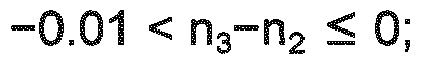
the glass fiber further includes a second annular region (53) of transparent material adjacent to the outer cladding whose refractive index is n4 , wherein
- The distributed Brillouin sensor system according to claim 6, wherein the radiusses c1, c2, c3 of the centrel core region (51) and the two annular regions (52, 53) are


- The distributed Brillouin sensor system according to claim 1, wherein the Brillouin sensor fiber exhibits the mentioned characteristics for all wavelengths in the region 1530-1565 nm.
- The distributed Brillouin sensor system according to claim 1, wherein the pump signal is composed of optical pulses.
- The distributed Brillouin sensor according to claim 2, wherein the probe signal is composed of continuous wave light.
- The distributed Brillouin sensor according to claim 1, wherein the Brillouin sensor fiber has a length of at least 5 km, advantageously at least 10 km.
- Use of a sensor fiber in a Brillouin sensor fiber system according to any of the claims 1 to 11 wherein the sensor fiber has a high Brillouin gain and a negative dispersion, which is more negative than - 2 ps/nm/km, wherein an effective area of the sensor fiber is less than or equal to 40 2 µm, and wherein the attenuation is less than 0.25 dB/km.
- Use of a sensor fiber in a Brillouin sensor system according to any of the claims 1 to 11, wherein the sensor fiber comprises a central core region having a maximum refractive index, n1, and a layer of transparent cladding material on the outer surface of said glass fiber having a nominal refractive index of n2, wherein

the glass fiber includes a first annular region of transparent material adjacent to the central core region, said first annular region having a width of about 1-10 micrometers and a refractive index, n3, wherein
the glass fiber further includes a second annular region of transparent material adjacent to the outer cladding whose refractive index is n4, wherein
Applications Claiming Priority (3)
| Application Number | Priority Date | Filing Date | Title |
|---|---|---|---|
| US201462074201P | 2014-11-03 | 2014-11-03 | |
| US201562133627P | 2015-03-16 | 2015-03-16 | |
| US14/927,699 US9874519B2 (en) | 2014-11-03 | 2015-10-30 | Distributed Brillouin sensor |
Publications (2)
| Publication Number | Publication Date |
|---|---|
| EP3023749A1 EP3023749A1 (en) | 2016-05-25 |
| EP3023749B1 true EP3023749B1 (en) | 2018-07-04 |
Family
ID=56102464
Family Applications (1)
| Application Number | Title | Priority Date | Filing Date |
|---|---|---|---|
| EP15192711.8A Active EP3023749B1 (en) | 2014-11-03 | 2015-11-03 | A distributed brillouin sensor |
Country Status (2)
| Country | Link |
|---|---|
| EP (1) | EP3023749B1 (en) |
| JP (1) | JP6165821B2 (en) |
Families Citing this family (2)
| Publication number | Priority date | Publication date | Assignee | Title |
|---|---|---|---|---|
| US10401563B2 (en) * | 2017-12-14 | 2019-09-03 | Ofs Fitel, Llc | Optical fibers for simultaneous measurement of temperature and strain |
| US11132542B2 (en) * | 2018-06-28 | 2021-09-28 | Nec Corporation | Time-space de-noising for distributed sensors |
Family Cites Families (3)
| Publication number | Priority date | Publication date | Assignee | Title |
|---|---|---|---|---|
| GB2397121B (en) * | 2002-12-20 | 2005-06-08 | Sensor Highway Ltd | System and method to minimize modulation instability |
| WO2007104915A1 (en) * | 2006-03-14 | 2007-09-20 | Schlumberger Holdings Limited | System and method for monitoring structures |
| GB0912851D0 (en) * | 2009-07-23 | 2009-08-26 | Fotech Solutions Ltd | Distributed optical fibre sensing |
-
2015
- 2015-11-02 JP JP2015215667A patent/JP6165821B2/en active Active
- 2015-11-03 EP EP15192711.8A patent/EP3023749B1/en active Active
Non-Patent Citations (1)
| Title |
|---|
| None * |
Also Published As
| Publication number | Publication date |
|---|---|
| JP2016105078A (en) | 2016-06-09 |
| EP3023749A1 (en) | 2016-05-25 |
| JP6165821B2 (en) | 2017-07-19 |
Similar Documents
| Publication | Publication Date | Title |
|---|---|---|
| EP3023748B1 (en) | A distributed brillouin sensor | |
| US8744782B2 (en) | System and method for simultaneously determining strain and temperature characteristics of an object | |
| US10317255B2 (en) | Distributed fiber sensors and systems employing hybridcore optical fibers | |
| US10591666B2 (en) | Two-core optical fibers for distributed fiber sensors and systems | |
| US4163397A (en) | Optical strain gauge | |
| EP2702353B1 (en) | Distributed brillouin sensing systems and methods using few-mode sensing optical fiber | |
| US8520197B2 (en) | Distributed optical fibre sensing | |
| Gao et al. | Multi-wavelength ultra-weak fiber Bragg grating arrays for long-distance quasi-distributed sensing | |
| KR20140135196A (en) | Sensing systems and few-mode optical fiber for use in such systems | |
| US10294146B2 (en) | Single mode optical fibers with Brillouin frequency-shift management | |
| CN107132615B (en) | Multimode optical fiber, application thereof and temperature measurement system | |
| US9874519B2 (en) | Distributed Brillouin sensor | |
| EP2795260B1 (en) | Fiber sensing system based on a bragg grating and optical time domain reflectometry | |
| CN110186547A (en) | Device and method for detecting pipeline safety status | |
| US20220334007A1 (en) | Broad bandwidth graded index multimode optical fiber for distributed temperature sensing in the 1550 nm region | |
| Song et al. | 151-km single-end phase-sensitive optical time-domain reflectometer assisted by optical repeater | |
| EP3023749B1 (en) | A distributed brillouin sensor | |
| US11906334B2 (en) | Fibre optic cables | |
| CN113092082B (en) | OPGW Optical Cable Life Prediction System | |
| Bao | Optical fiber sensors based on Brillouin scattering | |
| Dragic | Novel dual-Brillouin-frequency optical fiber for distributed temperature sensing | |
| Weng et al. | Few-mode distributed optical fiber sensors | |
| Herrera et al. | Micro-drilled optical fiber for enhanced laser strain sensors | |
| CA2629446A1 (en) | Method and system for simultaneous measurement of strain and temperature | |
| Kim et al. | A novel fiber optic temperature monitoring sensor using hard-polymer-clad fiber and an optical time-domain reflectometer |
Legal Events
| Date | Code | Title | Description |
|---|---|---|---|
| AK | Designated contracting states |
Kind code of ref document: A1 Designated state(s): AL AT BE BG CH CY CZ DE DK EE ES FI FR GB GR HR HU IE IS IT LI LT LU LV MC MK MT NL NO PL PT RO RS SE SI SK SM TR |
|
| AX | Request for extension of the european patent |
Extension state: BA ME |
|
| PUAI | Public reference made under article 153(3) epc to a published international application that has entered the european phase |
Free format text: ORIGINAL CODE: 0009012 |
|
| 17P | Request for examination filed |
Effective date: 20161108 |
|
| RBV | Designated contracting states (corrected) |
Designated state(s): AL AT BE BG CH CY CZ DE DK EE ES FI FR GB GR HR HU IE IS IT LI LT LU LV MC MK MT NL NO PL PT RO RS SE SI SK SM TR |
|
| 17Q | First examination report despatched |
Effective date: 20170726 |
|
| GRAP | Despatch of communication of intention to grant a patent |
Free format text: ORIGINAL CODE: EPIDOSNIGR1 |
|
| RIC1 | Information provided on ipc code assigned before grant |
Ipc: G02B 6/036 20060101ALN20171220BHEP Ipc: G01N 21/63 20060101ALI20171220BHEP Ipc: G01D 5/353 20060101AFI20171220BHEP Ipc: G02B 6/02 20060101ALN20171220BHEP |
|
| INTG | Intention to grant announced |
Effective date: 20180119 |
|
| INTG | Intention to grant announced |
Effective date: 20180119 |
|
| GRAS | Grant fee paid |
Free format text: ORIGINAL CODE: EPIDOSNIGR3 |
|
| GRAA | (expected) grant |
Free format text: ORIGINAL CODE: 0009210 |
|
| AK | Designated contracting states |
Kind code of ref document: B1 Designated state(s): AL AT BE BG CH CY CZ DE DK EE ES FI FR GB GR HR HU IE IS IT LI LT LU LV MC MK MT NL NO PL PT RO RS SE SI SK SM TR |
|
| REG | Reference to a national code |
Ref country code: GB Ref legal event code: FG4D |
|
| REG | Reference to a national code |
Ref country code: CH Ref legal event code: EP |
|
| REG | Reference to a national code |
Ref country code: AT Ref legal event code: REF Ref document number: 1015002 Country of ref document: AT Kind code of ref document: T Effective date: 20180715 |
|
| REG | Reference to a national code |
Ref country code: IE Ref legal event code: FG4D |
|
| REG | Reference to a national code |
Ref country code: DE Ref legal event code: R096 Ref document number: 602015012956 Country of ref document: DE |
|
| REG | Reference to a national code |
Ref country code: NL Ref legal event code: MP Effective date: 20180704 |
|
| REG | Reference to a national code |
Ref country code: LT Ref legal event code: MG4D |
|
| REG | Reference to a national code |
Ref country code: AT Ref legal event code: MK05 Ref document number: 1015002 Country of ref document: AT Kind code of ref document: T Effective date: 20180704 |
|
| PG25 | Lapsed in a contracting state [announced via postgrant information from national office to epo] |
Ref country code: NL Free format text: LAPSE BECAUSE OF FAILURE TO SUBMIT A TRANSLATION OF THE DESCRIPTION OR TO PAY THE FEE WITHIN THE PRESCRIBED TIME-LIMIT Effective date: 20180704 |
|
| PG25 | Lapsed in a contracting state [announced via postgrant information from national office to epo] |
Ref country code: CZ Free format text: LAPSE BECAUSE OF FAILURE TO SUBMIT A TRANSLATION OF THE DESCRIPTION OR TO PAY THE FEE WITHIN THE PRESCRIBED TIME-LIMIT Effective date: 20180704 Ref country code: LT Free format text: LAPSE BECAUSE OF FAILURE TO SUBMIT A TRANSLATION OF THE DESCRIPTION OR TO PAY THE FEE WITHIN THE PRESCRIBED TIME-LIMIT Effective date: 20180704 Ref country code: PL Free format text: LAPSE BECAUSE OF FAILURE TO SUBMIT A TRANSLATION OF THE DESCRIPTION OR TO PAY THE FEE WITHIN THE PRESCRIBED TIME-LIMIT Effective date: 20180704 Ref country code: IS Free format text: LAPSE BECAUSE OF FAILURE TO SUBMIT A TRANSLATION OF THE DESCRIPTION OR TO PAY THE FEE WITHIN THE PRESCRIBED TIME-LIMIT Effective date: 20181104 Ref country code: AT Free format text: LAPSE BECAUSE OF FAILURE TO SUBMIT A TRANSLATION OF THE DESCRIPTION OR TO PAY THE FEE WITHIN THE PRESCRIBED TIME-LIMIT Effective date: 20180704 Ref country code: BG Free format text: LAPSE BECAUSE OF FAILURE TO SUBMIT A TRANSLATION OF THE DESCRIPTION OR TO PAY THE FEE WITHIN THE PRESCRIBED TIME-LIMIT Effective date: 20181004 Ref country code: SE Free format text: LAPSE BECAUSE OF FAILURE TO SUBMIT A TRANSLATION OF THE DESCRIPTION OR TO PAY THE FEE WITHIN THE PRESCRIBED TIME-LIMIT Effective date: 20180704 Ref country code: FI Free format text: LAPSE BECAUSE OF FAILURE TO SUBMIT A TRANSLATION OF THE DESCRIPTION OR TO PAY THE FEE WITHIN THE PRESCRIBED TIME-LIMIT Effective date: 20180704 Ref country code: NO Free format text: LAPSE BECAUSE OF FAILURE TO SUBMIT A TRANSLATION OF THE DESCRIPTION OR TO PAY THE FEE WITHIN THE PRESCRIBED TIME-LIMIT Effective date: 20181004 Ref country code: GR Free format text: LAPSE BECAUSE OF FAILURE TO SUBMIT A TRANSLATION OF THE DESCRIPTION OR TO PAY THE FEE WITHIN THE PRESCRIBED TIME-LIMIT Effective date: 20181005 Ref country code: RS Free format text: LAPSE BECAUSE OF FAILURE TO SUBMIT A TRANSLATION OF THE DESCRIPTION OR TO PAY THE FEE WITHIN THE PRESCRIBED TIME-LIMIT Effective date: 20180704 |
|
| PG25 | Lapsed in a contracting state [announced via postgrant information from national office to epo] |
Ref country code: ES Free format text: LAPSE BECAUSE OF FAILURE TO SUBMIT A TRANSLATION OF THE DESCRIPTION OR TO PAY THE FEE WITHIN THE PRESCRIBED TIME-LIMIT Effective date: 20180704 Ref country code: LV Free format text: LAPSE BECAUSE OF FAILURE TO SUBMIT A TRANSLATION OF THE DESCRIPTION OR TO PAY THE FEE WITHIN THE PRESCRIBED TIME-LIMIT Effective date: 20180704 Ref country code: HR Free format text: LAPSE BECAUSE OF FAILURE TO SUBMIT A TRANSLATION OF THE DESCRIPTION OR TO PAY THE FEE WITHIN THE PRESCRIBED TIME-LIMIT Effective date: 20180704 Ref country code: AL Free format text: LAPSE BECAUSE OF FAILURE TO SUBMIT A TRANSLATION OF THE DESCRIPTION OR TO PAY THE FEE WITHIN THE PRESCRIBED TIME-LIMIT Effective date: 20180704 |
|
| REG | Reference to a national code |
Ref country code: DE Ref legal event code: R097 Ref document number: 602015012956 Country of ref document: DE |
|
| PG25 | Lapsed in a contracting state [announced via postgrant information from national office to epo] |
Ref country code: EE Free format text: LAPSE BECAUSE OF FAILURE TO SUBMIT A TRANSLATION OF THE DESCRIPTION OR TO PAY THE FEE WITHIN THE PRESCRIBED TIME-LIMIT Effective date: 20180704 Ref country code: IT Free format text: LAPSE BECAUSE OF FAILURE TO SUBMIT A TRANSLATION OF THE DESCRIPTION OR TO PAY THE FEE WITHIN THE PRESCRIBED TIME-LIMIT Effective date: 20180704 Ref country code: RO Free format text: LAPSE BECAUSE OF FAILURE TO SUBMIT A TRANSLATION OF THE DESCRIPTION OR TO PAY THE FEE WITHIN THE PRESCRIBED TIME-LIMIT Effective date: 20180704 |
|
| PLBE | No opposition filed within time limit |
Free format text: ORIGINAL CODE: 0009261 |
|
| STAA | Information on the status of an ep patent application or granted ep patent |
Free format text: STATUS: NO OPPOSITION FILED WITHIN TIME LIMIT |
|
| PG25 | Lapsed in a contracting state [announced via postgrant information from national office to epo] |
Ref country code: SK Free format text: LAPSE BECAUSE OF FAILURE TO SUBMIT A TRANSLATION OF THE DESCRIPTION OR TO PAY THE FEE WITHIN THE PRESCRIBED TIME-LIMIT Effective date: 20180704 Ref country code: DK Free format text: LAPSE BECAUSE OF FAILURE TO SUBMIT A TRANSLATION OF THE DESCRIPTION OR TO PAY THE FEE WITHIN THE PRESCRIBED TIME-LIMIT Effective date: 20180704 Ref country code: SM Free format text: LAPSE BECAUSE OF FAILURE TO SUBMIT A TRANSLATION OF THE DESCRIPTION OR TO PAY THE FEE WITHIN THE PRESCRIBED TIME-LIMIT Effective date: 20180704 |
|
| 26N | No opposition filed |
Effective date: 20190405 |
|
| REG | Reference to a national code |
Ref country code: CH Ref legal event code: PL |
|
| PG25 | Lapsed in a contracting state [announced via postgrant information from national office to epo] |
Ref country code: MC Free format text: LAPSE BECAUSE OF FAILURE TO SUBMIT A TRANSLATION OF THE DESCRIPTION OR TO PAY THE FEE WITHIN THE PRESCRIBED TIME-LIMIT Effective date: 20180704 Ref country code: LU Free format text: LAPSE BECAUSE OF NON-PAYMENT OF DUE FEES Effective date: 20181103 |
|
| REG | Reference to a national code |
Ref country code: BE Ref legal event code: MM Effective date: 20181130 |
|
| REG | Reference to a national code |
Ref country code: IE Ref legal event code: MM4A |
|
| PG25 | Lapsed in a contracting state [announced via postgrant information from national office to epo] |
Ref country code: SI Free format text: LAPSE BECAUSE OF FAILURE TO SUBMIT A TRANSLATION OF THE DESCRIPTION OR TO PAY THE FEE WITHIN THE PRESCRIBED TIME-LIMIT Effective date: 20180704 Ref country code: CH Free format text: LAPSE BECAUSE OF NON-PAYMENT OF DUE FEES Effective date: 20181130 Ref country code: LI Free format text: LAPSE BECAUSE OF NON-PAYMENT OF DUE FEES Effective date: 20181130 |
|
| PG25 | Lapsed in a contracting state [announced via postgrant information from national office to epo] |
Ref country code: IE Free format text: LAPSE BECAUSE OF NON-PAYMENT OF DUE FEES Effective date: 20181103 |
|
| PG25 | Lapsed in a contracting state [announced via postgrant information from national office to epo] |
Ref country code: BE Free format text: LAPSE BECAUSE OF NON-PAYMENT OF DUE FEES Effective date: 20181130 |
|
| PG25 | Lapsed in a contracting state [announced via postgrant information from national office to epo] |
Ref country code: MT Free format text: LAPSE BECAUSE OF NON-PAYMENT OF DUE FEES Effective date: 20181103 |
|
| PG25 | Lapsed in a contracting state [announced via postgrant information from national office to epo] |
Ref country code: TR Free format text: LAPSE BECAUSE OF FAILURE TO SUBMIT A TRANSLATION OF THE DESCRIPTION OR TO PAY THE FEE WITHIN THE PRESCRIBED TIME-LIMIT Effective date: 20180704 |
|
| PG25 | Lapsed in a contracting state [announced via postgrant information from national office to epo] |
Ref country code: PT Free format text: LAPSE BECAUSE OF FAILURE TO SUBMIT A TRANSLATION OF THE DESCRIPTION OR TO PAY THE FEE WITHIN THE PRESCRIBED TIME-LIMIT Effective date: 20180704 |
|
| PG25 | Lapsed in a contracting state [announced via postgrant information from national office to epo] |
Ref country code: HU Free format text: LAPSE BECAUSE OF FAILURE TO SUBMIT A TRANSLATION OF THE DESCRIPTION OR TO PAY THE FEE WITHIN THE PRESCRIBED TIME-LIMIT; INVALID AB INITIO Effective date: 20151103 Ref country code: CY Free format text: LAPSE BECAUSE OF FAILURE TO SUBMIT A TRANSLATION OF THE DESCRIPTION OR TO PAY THE FEE WITHIN THE PRESCRIBED TIME-LIMIT Effective date: 20180704 Ref country code: MK Free format text: LAPSE BECAUSE OF NON-PAYMENT OF DUE FEES Effective date: 20180704 |
|
| P01 | Opt-out of the competence of the unified patent court (upc) registered |
Effective date: 20230411 |
|
| PGFP | Annual fee paid to national office [announced via postgrant information from national office to epo] |
Ref country code: DE Payment date: 20251128 Year of fee payment: 11 |
|
| PGFP | Annual fee paid to national office [announced via postgrant information from national office to epo] |
Ref country code: GB Payment date: 20251127 Year of fee payment: 11 |
|
| PGFP | Annual fee paid to national office [announced via postgrant information from national office to epo] |
Ref country code: FR Payment date: 20251125 Year of fee payment: 11 |