EP3023624A1 - Gas turbine engine and method of assembling the same - Google Patents
Gas turbine engine and method of assembling the same Download PDFInfo
- Publication number
- EP3023624A1 EP3023624A1 EP15195700.8A EP15195700A EP3023624A1 EP 3023624 A1 EP3023624 A1 EP 3023624A1 EP 15195700 A EP15195700 A EP 15195700A EP 3023624 A1 EP3023624 A1 EP 3023624A1
- Authority
- EP
- European Patent Office
- Prior art keywords
- actuators
- fan
- transcowl
- gas turbine
- turbine engine
- Prior art date
- Legal status (The legal status is an assumption and is not a legal conclusion. Google has not performed a legal analysis and makes no representation as to the accuracy of the status listed.)
- Granted
Links
Images








Classifications
-
- F—MECHANICAL ENGINEERING; LIGHTING; HEATING; WEAPONS; BLASTING
- F02—COMBUSTION ENGINES; HOT-GAS OR COMBUSTION-PRODUCT ENGINE PLANTS
- F02K—JET-PROPULSION PLANTS
- F02K1/00—Plants characterised by the form or arrangement of the jet pipe or nozzle; Jet pipes or nozzles peculiar thereto
- F02K1/54—Nozzles having means for reversing jet thrust
- F02K1/64—Reversing fan flow
- F02K1/70—Reversing fan flow using thrust reverser flaps or doors mounted on the fan housing
- F02K1/72—Reversing fan flow using thrust reverser flaps or doors mounted on the fan housing the aft end of the fan housing being movable to uncover openings in the fan housing for the reversed flow
-
- F—MECHANICAL ENGINEERING; LIGHTING; HEATING; WEAPONS; BLASTING
- F02—COMBUSTION ENGINES; HOT-GAS OR COMBUSTION-PRODUCT ENGINE PLANTS
- F02K—JET-PROPULSION PLANTS
- F02K3/00—Plants including a gas turbine driving a compressor or a ducted fan
- F02K3/02—Plants including a gas turbine driving a compressor or a ducted fan in which part of the working fluid by-passes the turbine and combustion chamber
- F02K3/04—Plants including a gas turbine driving a compressor or a ducted fan in which part of the working fluid by-passes the turbine and combustion chamber the plant including ducted fans, i.e. fans with high volume, low pressure outputs, for augmenting the jet thrust, e.g. of double-flow type
-
- F—MECHANICAL ENGINEERING; LIGHTING; HEATING; WEAPONS; BLASTING
- F02—COMBUSTION ENGINES; HOT-GAS OR COMBUSTION-PRODUCT ENGINE PLANTS
- F02K—JET-PROPULSION PLANTS
- F02K1/00—Plants characterised by the form or arrangement of the jet pipe or nozzle; Jet pipes or nozzles peculiar thereto
- F02K1/54—Nozzles having means for reversing jet thrust
- F02K1/64—Reversing fan flow
- F02K1/66—Reversing fan flow using reversing fan blades
-
- F—MECHANICAL ENGINEERING; LIGHTING; HEATING; WEAPONS; BLASTING
- F02—COMBUSTION ENGINES; HOT-GAS OR COMBUSTION-PRODUCT ENGINE PLANTS
- F02K—JET-PROPULSION PLANTS
- F02K1/00—Plants characterised by the form or arrangement of the jet pipe or nozzle; Jet pipes or nozzles peculiar thereto
- F02K1/54—Nozzles having means for reversing jet thrust
- F02K1/76—Control or regulation of thrust reversers
- F02K1/763—Control or regulation of thrust reversers with actuating systems or actuating devices; Arrangement of actuators for thrust reversers
-
- F—MECHANICAL ENGINEERING; LIGHTING; HEATING; WEAPONS; BLASTING
- F04—POSITIVE - DISPLACEMENT MACHINES FOR LIQUIDS; PUMPS FOR LIQUIDS OR ELASTIC FLUIDS
- F04D—NON-POSITIVE-DISPLACEMENT PUMPS
- F04D19/00—Axial-flow pumps
- F04D19/002—Axial flow fans
-
- F—MECHANICAL ENGINEERING; LIGHTING; HEATING; WEAPONS; BLASTING
- F04—POSITIVE - DISPLACEMENT MACHINES FOR LIQUIDS; PUMPS FOR LIQUIDS OR ELASTIC FLUIDS
- F04D—NON-POSITIVE-DISPLACEMENT PUMPS
- F04D27/00—Control, e.g. regulation, of pumps, pumping installations or pumping systems specially adapted for elastic fluids
- F04D27/002—Control, e.g. regulation, of pumps, pumping installations or pumping systems specially adapted for elastic fluids by varying geometry within the pumps, e.g. by adjusting vanes
-
- F—MECHANICAL ENGINEERING; LIGHTING; HEATING; WEAPONS; BLASTING
- F05—INDEXING SCHEMES RELATING TO ENGINES OR PUMPS IN VARIOUS SUBCLASSES OF CLASSES F01-F04
- F05D—INDEXING SCHEME FOR ASPECTS RELATING TO NON-POSITIVE-DISPLACEMENT MACHINES OR ENGINES, GAS-TURBINES OR JET-PROPULSION PLANTS
- F05D2220/00—Application
- F05D2220/30—Application in turbines
- F05D2220/32—Application in turbines in gas turbines
-
- F—MECHANICAL ENGINEERING; LIGHTING; HEATING; WEAPONS; BLASTING
- F05—INDEXING SCHEMES RELATING TO ENGINES OR PUMPS IN VARIOUS SUBCLASSES OF CLASSES F01-F04
- F05D—INDEXING SCHEME FOR ASPECTS RELATING TO NON-POSITIVE-DISPLACEMENT MACHINES OR ENGINES, GAS-TURBINES OR JET-PROPULSION PLANTS
- F05D2230/00—Manufacture
- F05D2230/60—Assembly methods
-
- F—MECHANICAL ENGINEERING; LIGHTING; HEATING; WEAPONS; BLASTING
- F05—INDEXING SCHEMES RELATING TO ENGINES OR PUMPS IN VARIOUS SUBCLASSES OF CLASSES F01-F04
- F05D—INDEXING SCHEME FOR ASPECTS RELATING TO NON-POSITIVE-DISPLACEMENT MACHINES OR ENGINES, GAS-TURBINES OR JET-PROPULSION PLANTS
- F05D2240/00—Components
- F05D2240/10—Stators
- F05D2240/12—Fluid guiding means, e.g. vanes
-
- F—MECHANICAL ENGINEERING; LIGHTING; HEATING; WEAPONS; BLASTING
- F05—INDEXING SCHEMES RELATING TO ENGINES OR PUMPS IN VARIOUS SUBCLASSES OF CLASSES F01-F04
- F05D—INDEXING SCHEME FOR ASPECTS RELATING TO NON-POSITIVE-DISPLACEMENT MACHINES OR ENGINES, GAS-TURBINES OR JET-PROPULSION PLANTS
- F05D2250/00—Geometry
- F05D2250/20—Three-dimensional
- F05D2250/24—Three-dimensional ellipsoidal
- F05D2250/241—Three-dimensional ellipsoidal spherical
-
- F—MECHANICAL ENGINEERING; LIGHTING; HEATING; WEAPONS; BLASTING
- F05—INDEXING SCHEMES RELATING TO ENGINES OR PUMPS IN VARIOUS SUBCLASSES OF CLASSES F01-F04
- F05D—INDEXING SCHEME FOR ASPECTS RELATING TO NON-POSITIVE-DISPLACEMENT MACHINES OR ENGINES, GAS-TURBINES OR JET-PROPULSION PLANTS
- F05D2250/00—Geometry
- F05D2250/30—Arrangement of components
- F05D2250/31—Arrangement of components according to the direction of their main axis or their axis of rotation
- F05D2250/314—Arrangement of components according to the direction of their main axis or their axis of rotation the axes being inclined in relation to each other
-
- F—MECHANICAL ENGINEERING; LIGHTING; HEATING; WEAPONS; BLASTING
- F05—INDEXING SCHEMES RELATING TO ENGINES OR PUMPS IN VARIOUS SUBCLASSES OF CLASSES F01-F04
- F05D—INDEXING SCHEME FOR ASPECTS RELATING TO NON-POSITIVE-DISPLACEMENT MACHINES OR ENGINES, GAS-TURBINES OR JET-PROPULSION PLANTS
- F05D2250/00—Geometry
- F05D2250/30—Arrangement of components
- F05D2250/34—Arrangement of components translated
-
- F—MECHANICAL ENGINEERING; LIGHTING; HEATING; WEAPONS; BLASTING
- F05—INDEXING SCHEMES RELATING TO ENGINES OR PUMPS IN VARIOUS SUBCLASSES OF CLASSES F01-F04
- F05D—INDEXING SCHEME FOR ASPECTS RELATING TO NON-POSITIVE-DISPLACEMENT MACHINES OR ENGINES, GAS-TURBINES OR JET-PROPULSION PLANTS
- F05D2250/00—Geometry
- F05D2250/50—Inlet or outlet
- F05D2250/51—Inlet
-
- F—MECHANICAL ENGINEERING; LIGHTING; HEATING; WEAPONS; BLASTING
- F05—INDEXING SCHEMES RELATING TO ENGINES OR PUMPS IN VARIOUS SUBCLASSES OF CLASSES F01-F04
- F05D—INDEXING SCHEME FOR ASPECTS RELATING TO NON-POSITIVE-DISPLACEMENT MACHINES OR ENGINES, GAS-TURBINES OR JET-PROPULSION PLANTS
- F05D2270/00—Control
- F05D2270/60—Control system actuates means
- F05D2270/64—Hydraulic actuators
Definitions
- the field of this disclosure relates generally to a gas turbine engine and, more particularly, to a gas turbine engine having a transcowl that facilitates providing airflow to a variable pitch fan in reverse thrust mode.
- Many known gas turbine engines have a ducted fan and a core arranged in flow communication with one another.
- the fan provides air to the core (a "core flow”) and to a bypass duct surrounding the core (a “bypass flow”).
- the core compresses the core flow and subsequently mixes it with fuel for igniting the mixture to generate a flow of combustion gas through a turbine.
- the combustion gas drives the turbine, which in turn drives the fan to generate the core flow and the bypass flow.
- some known fans have blades for which the pitch can be varied to facilitate controlling the thrust.
- these fans can be configured such that the blades, at one pitch angle, generate an aftward directed bypass flow resulting in forward thrust, and, at another pitch angle, generate a forward directed bypass flow resulting in reverse thrust.
- the condition of the bypass flow is often less than optimal in both directions. As such, for gas turbine engines having variable pitch fans, it would be useful to improve the condition of the bypass flow.
- a gas turbine engine having a centerline axis includes a fan and a fan cowl assembly surrounding the fan to define a bypass duct configured to channel airflow for the fan.
- the fan cowl assembly includes a stationary cowl and a transcowl.
- the gas turbine engine further includes a plurality of actuators configured for displacing the transcowl relative to the stationary cowl. Each of the actuators is skewed relative to the centerline axis of the engine.
- a method of assembling a gas turbine engine having a centerline axis includes providing a fan and surrounding the fan with a fan cowl assembly to define a bypass duct configured to channel airflow for the fan.
- the fan cowl assembly includes a stationary cowl and a transcowl, and the method further includes coupling the tanscowl to the stationary cowl via a plurality of actuators configured for displacing the transcowl relative to the stationary cowl. Each of the actuators is skewed relative to the centerline axis of the engine.
- a gas turbine engine having a centerline axis in another aspect, includes a variable pitch fan and a fan cowl assembly surrounding the fan to define a bypass duct configured to channel airflow for the fan.
- the fan cowl assembly includes a stationary cowl and a transcowl.
- the gas turbine engine further includes at least six actuators coupling the stationary cowl to the transcowl such that the transcowl is displaceable relative to the stationary cowl via the actuators to define an auxiliary inlet for airflow into the bypass duct.
- the actuators are circumferentially spaced apart from one another and are alternatingly skewed relative to the centerline axis so as to be triangulated.
- transcowl for a gas turbine engine and a method of assembling the same by way of example and not by way of limitation.
- the description should clearly enable one of ordinary skill in the art to make and use the transcowl, and the description sets forth several embodiments, adaptations, variations, alternatives, and uses of the transcowl, including what is presently believed to be the best mode thereof.
- the transcowl is described herein as being applied to a preferred embodiment, namely a thrust reverser for a gas turbine engine.
- the transcowl and the methods of assembling the transcowl may have general application in a broad range of systems and/or a variety of commercial, industrial, and/or consumer applications other than thrust reversers for gas turbine engines.
- FIGS 1 and 2 are schematic illustrations of a gas turbine engine 100 having a fan 102 and a core 104 arranged in flow communication with one another along a centerline axis 106 of engine 100.
- Fan 102 provides air to core 104 which, in turn, drives fan 102 to produce thrust for engine 100.
- Fan 102 is a variable pitch fan, meaning that the pitch of its blades 108 can be selectively varied to generate forward thrust or reverse thrust for engine 100.
- a fan cowl assembly 110 surrounds fan 102 and includes a stationary cowl 112 and a transcowl 114 that collectively define a substantially annular bypass duct 116 about core 104 for channeling airflow for fan 102.
- transcowl 114 and stationary cowl 112 abut one another such that airflow enters bypass duct 116 through a forward inlet 118 of bypass duct 116, and exits bypass duct 116 through an aft outlet 120 of bypass duct 116 (i.e., air flows through bypass duct 116 in a forward to aft direction).
- transcowl 114 is axially spaced apart from stationary cowl 112 to create an auxiliary inlet 122 for air entering bypass duct 116.
- forward inlet 118 becomes a forward outlet 124
- aft outlet 120 becomes an aft inlet 126.
- auxiliary inlet 122 facilitates providing airflow into bypass duct 116 in a more controlled and stable manner than had the airflow entered bypass duct 116 from aft inlet 126 alone, since airflow entering bypass duct 116 from aft inlet 126 tends to experience more flow separation and, therefore, tends to be less controlled than airflow entering bypass duct 116 through auxiliary inlet 122.
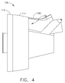
- Figures 3 and 4 are perspective views of an aft segment 128 of gas turbine engine 100, and aft segment 128 is configured for forward thrust mode ( Figure 1 ), in that transcowl 114 is in abutment with stationary cowl 112.
- aft segment 128 is configured for reverse thrust mode ( Figure 2 ), in that transcowl 114 is axially spaced apart from stationary cowl 112 to create auxiliary inlet 122.
- engine 100 is provided with an actuator assembly 130 for displacing transcowl 114 relative to stationary cowl 112 in translation substantially parallel to centerline axis 106.
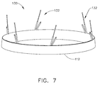
- actuator assembly 130 includes six actuators 132 (a minimum of six actuators 132 equating to the six theoretical degrees of freedom of transcowl 114 in its displacement relative to stationary cowl 112).
- actuator assembly 130 may have more than six actuators 132.
- each of the illustrated actuators 132 is in the form of a linear actuator having a cylinder 134, a piston 136 slidably inserted into cylinder 134, a first pin joint (e.g., a first spherical bearing 138) mounted on cylinder 134, and a second pin joint (e.g., a second spherical bearing 140) mounted on piston 136.
- First spherical bearings 138 connect actuators 132 to stationary cowl 112, and second spherical bearings 140 connect actuators 132 to transcowl 114. In this manner, actuators 132 connect transcowl 114 to stationary cowl 112, and function to displace transcowl 114 relative to stationary cowl 112 when deployed.
- actuators 132 are circumferentially spaced apart in their arrangement between stationary cowl 112 and transcowl 114; and, when displacing transcowl 114 relative to stationary cowl 112, each actuator 132 pivots circumferentially during its transition from a stowed state 142 (in which transcowl 114 abuts stationary cowl 112) and a deployed state 144 (in which transcowl 114 is spaced apart from stationary cowl 112).
- each actuator 132 when transcowl 114 is in abutment with stationary cowl 112, each actuator 132 is said to be in its stowed state 142; and, when transcowl 114 is fully spaced from stationary cowl 112, each actuator 132 is said to be in its deployed state 144.
- each actuator 132 is shown in both its stowed state 142 and its deployed state 144, which are separated by a V-shaped spacing 146 that represents the circumferential pivoting that each actuator 132 undergoes during its transition from stowed state 142 to deployed state 144 as described below.
- FIG. 9 Illustrated in Figure 9 is a diagram of the configuration and function of actuators 132.
- the circumferential arrangement of actuators 132 has been projected onto a plane (i.e., the annular formation of actuators 132 has been separated at a seam 148 and flattened for illustration purposes).
- each actuator 132 is represented in its stowed state 142 by a stowed actuator line 150, and in its deployed state 144 by a deployed actuator line 152.
- centerline axis 106 of engine 100 is represented by an axis line 154, and the difference in length between the various stowed actuator lines 150 and the various deployed actuator lines 152 along axis line 154 represents a displacement range 156 of transcowl 114.
- actuators 132 are circumferentially spaced apart about centerline axis 106 and are oriented in an alternatingly skewed manner relative centerline axis 106 and relative to one another. More specifically, the first, third, and fifth stowed actuator lines 150 (from left to right on the diagram) are oriented in a clockwise direction 158 in their forward-aft extension 163 so as to be skewed relative to (i.e., not parallel with) axis line 154.
- the second, third, and sixth stowed actuator lines 150 are oriented in a counterclockwise direction 160 in their forward-aft extension 163 so as to be skewed relative to axis line 154.
- a spacing 162 between adjacent actuators 132 is, in terms of the diagram, generally triangular in shape when actuators 132 are in their stowed states 142.
- actuators 132 remain skewed and continue to have generally triangular spacing 162 in their deployed states 144 as well.
- each actuator 132 is permitted to pivot in a circumferential direction (i.e., in clockwise direction 158 or counterclockwise direction 160) when transitioning from being stowed to being deployed. More specifically, in its transition from stowed state 142 to deployed state 144, each clockwise-oriented actuator 132 (i.e., each of the first, third, and fifth actuators 132) pivots in counterclockwise direction 160, and each counterclockwise-oriented actuator 132 (i.e., each of the second, fourth, and sixth actuators 132) pivots in clockwise direction 158.
- each clockwise-oriented actuator 132 i.e., each of the first, third, and fifth actuators 132
- each counterclockwise-oriented actuator 132 i.e., each of the second, fourth, and sixth actuators 132
- each clockwise-oriented actuator 132 pivots in clockwise direction 158, and each counterclockwise-oriented actuator 132 pivots in counterclockwise direction 160.
- Such pivoting motion is represented in the diagram by spacing 164 between each stowed actuator line 150 and it associated deployed actuator line 152.
- actuators 132 may be oriented at any suitable angles relative to centerline axis 106 (i.e., actuators 132 cannot all be oriented parallel to centerline axis 106).
- the clockwise-oriented actuators 132 and the counterclockwise-oriented actuators 132 may have their stowed actuator lines 150 respectively angled at about 16° and -16° relative to axis line 154, with their deployed actuator lines 152 being respectively angled at about 30° and -30° relative to axis line 154 (such that spacing 164, or pivoting range, would be about 14°).
- actuator assembly 130 having six actuators 132 oriented and pivotable in this manner, better stabilization of transcowl 114 in its displacement relative to stationary cowl 112 is facilitated. More specifically, because adjacent actuators 132 are circumferentially angled in opposite directions, the support structure for transcowl 114 is effectively triangulated, making the support structure more stable (e.g., if actuators 132 were oriented parallel to one another and centerline axis 106, actuators 132 would be more susceptible to bending in response to vertical and lateral loads applied perpendicular to centerline axis 106).
- actuators 132 provide six alternatingly-skewed, fixed-length actuators 132 accounts for each of the six theoretical degrees of freedom of transcowl 114 which, in turn, results in a determinate solution for positioning transcowl 114 in space.
- actuators 132 When fully extended, actuators 132 have a known length and, therefore, transcowl 114 has a determinate deployed position.
- actuators 132 when retracted, actuators 132 have a known length, and the stowed transcowl 114 has a determinate position.
- minimal guidance e.g., no slider tracks
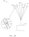
- Figure 10 illustrates a hydraulic system 166 for operating actuators 132.
- hydraulic system 166 includes a pump 168 and a plurality of conduits 170 for supplying hydraulic fluid from pump 168 to actuators 132 such that each actuator 132 has its own dedicated conduit 170.
- conduits 170 may be arranged in any suitable manner that facilitates enabling system 166 to function as described herein. While not shown in Figure 10 , system 166 also includes another plurality of conduits for returning hydraulic fluid from actuators 132 back to a suitable reservoir from which pump 168 draws fluid.
- actuators 132 should move at substantially the same rate.
- pumping hydraulic fluid along the various conduits 170 at substantially the same pressure does not, in and of itself, ensure substantially equal rates of motion amongst actuators 132 since each actuator 132 may have a different resistance to motion.
- a flow limiting member 172 is provided at the junction of each conduit 170 and each cylinder 134 of the associated actuator 132. Flow limiting members 172 collectively facilitate movement of actuators 132 at substantially the same rate despite any variation in resistance from one actuator 132 to the next.
- each flow limiting member 172 is in the form of a plate 174 having an orifice 176 with a diameter less than the diameter of its associated conduit 170 (e.g., conduit 170 may have a diameter of about 3/8", while orifice 176 may have a diameter of about 1/8").
- flow limiting member 172 may have any configuration that facilitates enabling hydraulic system 166 to function as described herein.
- orifices 176 function as a collective unit to facilitate applying substantially the same rate of fluid flow to pistons 136 despite any inherent resistance to displacement of pistons 136 that may exist amongst actuators 132. More specifically, because orifices 176 are smaller than their associated conduits 170, the pressure drop across each orifice 176 adjusts to cause a pressure decrease in actuators 132 that tend to experience less resistance, and an pressure increase in actuators 132 that tend to experience more resistance.
- actuators 132 experiencing lower resistance to displacement will tend to decelerate, and actuators 132 experiencing greater resistance to displacement will tend to accelerate.
- Hydraulic system 166 thereby establishes a tendency toward equal velocity and displacement amongst actuators 132 and, as a result, facilitates displacement of transcowl 114 in a more parallel manner relative to centerline axis 106.
- actuator assembly 130 is not provided with a mechanical synchronization mechanism (e.g., a synchronization cable) coupling actuators 132 together to facilitate movement of actuators 132 in unison.
- a mechanical synchronization mechanism e.g., a synchronization cable
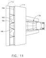
- FIG 11 illustrates that transcowl 114 is annular (i.e., tanscowl 114 extends in 360°) so as to wrap over a top surface 180 of a pylon fairing 178 associated with a pylon that suspends engine 100 from the wing of an aircraft.
- top surface 180 of pylon fairing 178 is intended to slide within the annular shape of transcowl 114
- top surface 180 of pylon fairing 178 is contoured (e.g., sloped downward) to mirror the interior contour of transcowl 114. As such, displacement of transcowl 114 is facilitated without interference from pylon fairing 178.
- contact wear strips may suitably be placed on top surface 180 and/or the side surfaces of pylon fairing 178 to aid in displacing transcowl 114 more smoothly in the event that transcowl 114 rubs against pylon fairing 178 mid-stroke due, for example, to gravity pulling transcowl 114 somewhat downward or a crosswind blowing transcowl 114 somewhat sideways.
- transcowl 114 is provided with a cutout 182 in its forward edge 184 at the top of its annulus, and a matching key 186 (i.e., a stationary filler piece) is provided on stationary cowl 112 and/or pylon fairing 178 for slidable insertion into cutout 182.
- Cutout 182 provides access to a tunnel formed in the top interior of transcowl 114 through which pylon fairing 178 may pass without interfering with transcowl 114.
- key 186 is inserted into cutout 182 when transcowl 114 is in abutment with stationary cowl 112, key 186 occupies space in the tunnel, resulting in a reduced affect of the tunnel on the flow area of bypass duct 116 when auxiliary inlet 122 is closed.
- Figures 12 and 13 illustrate a core cowl 188 of core 104.
- core cowl 188 is provided with a pair of substantially semi-annular doors 190 that are hingedly openable away from one another in a clamshell-like manner to provide access to operational components 192 of core 104 for servicing operational components 192 without having to remove, open, disassemble, or otherwise manipulate fan cowl assembly 110.
- the above-described embodiments facilitate providing improved airflow into a bypass duct during reverse thrust mode of a gas turbine engine.
- the above-described embodiments also facilitate effective displacement of a transcowl for a gas turbine engine and, in that regard, facilitate structurally supporting the transcowl in its displacement without the use of cumbersome support structures such as slider tracks. Additionally, the embodiments facilitate establishing a tendency for equal velocity and displacement of actuators used to displace a transcowl.
- the embodiments further facilitate providing easier access to core operating components of a gas turbine engine within a core cowl without disturbing a fan cowl assembly that surrounds the core cowl.
- a transcowl and a method of assembling the same are described above in detail.
- the methods and systems are not limited to the specific embodiments described herein, but rather, components of the methods and systems may be utilized independently and separately from other components described herein.
- the methods and systems described herein may have other industrial and/or consumer applications and are not limited to practice with only gas turbine engines as described herein. Rather, the present invention can be implemented and utilized in connection with many other industries.
Landscapes
- Engineering & Computer Science (AREA)
- Mechanical Engineering (AREA)
- General Engineering & Computer Science (AREA)
- Chemical & Material Sciences (AREA)
- Combustion & Propulsion (AREA)
- Physics & Mathematics (AREA)
- Geometry (AREA)
- Structures Of Non-Positive Displacement Pumps (AREA)
Abstract
Description
- The field of this disclosure relates generally to a gas turbine engine and, more particularly, to a gas turbine engine having a transcowl that facilitates providing airflow to a variable pitch fan in reverse thrust mode.
- Many known gas turbine engines have a ducted fan and a core arranged in flow communication with one another. The fan provides air to the core (a "core flow") and to a bypass duct surrounding the core (a "bypass flow"). The core compresses the core flow and subsequently mixes it with fuel for igniting the mixture to generate a flow of combustion gas through a turbine. The combustion gas drives the turbine, which in turn drives the fan to generate the core flow and the bypass flow.
- With the bypass flow being a source of thrust for the engine, some known fans have blades for which the pitch can be varied to facilitate controlling the thrust. In that regard, these fans can be configured such that the blades, at one pitch angle, generate an aftward directed bypass flow resulting in forward thrust, and, at another pitch angle, generate a forward directed bypass flow resulting in reverse thrust. However, in these known engines, the condition of the bypass flow is often less than optimal in both directions. As such, for gas turbine engines having variable pitch fans, it would be useful to improve the condition of the bypass flow.
- In one aspect, a gas turbine engine having a centerline axis is provided. The gas turbine engine includes a fan and a fan cowl assembly surrounding the fan to define a bypass duct configured to channel airflow for the fan. The fan cowl assembly includes a stationary cowl and a transcowl. The gas turbine engine further includes a plurality of actuators configured for displacing the transcowl relative to the stationary cowl. Each of the actuators is skewed relative to the centerline axis of the engine.
- In another aspect, a method of assembling a gas turbine engine having a centerline axis is provided. The method includes providing a fan and surrounding the fan with a fan cowl assembly to define a bypass duct configured to channel airflow for the fan. The fan cowl assembly includes a stationary cowl and a transcowl, and the method further includes coupling the tanscowl to the stationary cowl via a plurality of actuators configured for displacing the transcowl relative to the stationary cowl. Each of the actuators is skewed relative to the centerline axis of the engine.
- In another aspect, a gas turbine engine having a centerline axis is provided. The gas turbine engine includes a variable pitch fan and a fan cowl assembly surrounding the fan to define a bypass duct configured to channel airflow for the fan. The fan cowl assembly includes a stationary cowl and a transcowl. The gas turbine engine further includes at least six actuators coupling the stationary cowl to the transcowl such that the transcowl is displaceable relative to the stationary cowl via the actuators to define an auxiliary inlet for airflow into the bypass duct. The actuators are circumferentially spaced apart from one another and are alternatingly skewed relative to the centerline axis so as to be triangulated.
-
-
Figure 1 is a schematic representation of a gas turbine engine operating in forward thrust mode; -
Figure 2 is a schematic representation of the gas turbine engine shown inFigure 1 operating in reverse thrust mode; -
Figure 3 is a perspective view of an aft segment of the gas turbine engine shown inFigure 1 configured for the forward thrust mode ofFigure 1 ; -
Figure 4 is a side view of the aft segment configuration shown inFigure 3 ; -
Figure 5 is a perspective view of the aft segment shown inFigure 3 and configured for the reverse thrust mode ofFigure 2 ; -
Figure 6 is a side view of the aft segment configuration shown inFigure 5 ; -
Figure 7 is a perspective view of an actuator assembly for converting the aft segment between the configurations shown inFigure 3 andFigure 5 ; -
Figure 8 is a side view of an actuator of the actuator assembly shown inFigure 7 ; -
Figure 9 is a diagram illustrating the actuator assembly shown inFigure 7 when converting the aft segment between the configurations shown inFigure 3 andFigure 5 ; -
Figure 10 is a schematic representation of a hydraulic system for operating the actuator assembly shown inFigure 7 ; -
Figure 11 is a top view of the aft segment configuration shown inFigure 5 ; -
Figure 12 is a perspective view of the aft segment shown inFigure 3 with its core cowl open; and -
Figure 13 is a back view of the open core cowl shown inFigure 12 . - The following detailed description sets forth a transcowl for a gas turbine engine and a method of assembling the same by way of example and not by way of limitation. The description should clearly enable one of ordinary skill in the art to make and use the transcowl, and the description sets forth several embodiments, adaptations, variations, alternatives, and uses of the transcowl, including what is presently believed to be the best mode thereof. The transcowl is described herein as being applied to a preferred embodiment, namely a thrust reverser for a gas turbine engine. However, it is contemplated that the transcowl and the methods of assembling the transcowl may have general application in a broad range of systems and/or a variety of commercial, industrial, and/or consumer applications other than thrust reversers for gas turbine engines.
-
Figures 1 and2 are schematic illustrations of agas turbine engine 100 having afan 102 and acore 104 arranged in flow communication with one another along acenterline axis 106 ofengine 100. Fan 102 provides air tocore 104 which, in turn, drivesfan 102 to produce thrust forengine 100.Fan 102 is a variable pitch fan, meaning that the pitch of itsblades 108 can be selectively varied to generate forward thrust or reverse thrust forengine 100. Afan cowl assembly 110 surroundsfan 102 and includes astationary cowl 112 and atranscowl 114 that collectively define a substantiallyannular bypass duct 116 aboutcore 104 for channeling airflow forfan 102. - When
engine 100 is in its forward thrust mode (Figure 1 ),transcowl 114 andstationary cowl 112 abut one another such that airflow entersbypass duct 116 through aforward inlet 118 ofbypass duct 116, andexits bypass duct 116 through anaft outlet 120 of bypass duct 116 (i.e., air flows throughbypass duct 116 in a forward to aft direction). Whenengine 100 is in its reverse thrust mode (Figure 2 ), however,transcowl 114 is axially spaced apart fromstationary cowl 112 to create anauxiliary inlet 122 for air enteringbypass duct 116. Notably, in the reverse thrust mode,forward inlet 118 becomes aforward outlet 124, andaft outlet 120 becomes anaft inlet 126. As such, air flows intobypass duct 116 fromaft inlet 126 andauxiliary inlet 122, and airexits bypass duct 116 through forward outlet 124 (i.e., air flows throughbypass duct 116 in an aft to forward direction). In this manner,auxiliary inlet 122 facilitates providing airflow intobypass duct 116 in a more controlled and stable manner than had the airflow enteredbypass duct 116 fromaft inlet 126 alone, since airflow enteringbypass duct 116 fromaft inlet 126 tends to experience more flow separation and, therefore, tends to be less controlled than airflow enteringbypass duct 116 throughauxiliary inlet 122. -
Figures 3 and4 are perspective views of anaft segment 128 ofgas turbine engine 100, andaft segment 128 is configured for forward thrust mode (Figure 1 ), in thattranscowl 114 is in abutment withstationary cowl 112. InFigures 5 and6 , on the other hand,aft segment 128 is configured for reverse thrust mode (Figure 2 ), in thattranscowl 114 is axially spaced apart fromstationary cowl 112 to createauxiliary inlet 122. Notably,engine 100 is provided with anactuator assembly 130 for displacingtranscowl 114 relative tostationary cowl 112 in translation substantially parallel tocenterline axis 106. -
Figures 7 and8 illustrate actuator assembly 130 in more detail. In the exemplary embodiment,actuator assembly 130 includes six actuators 132 (a minimum of sixactuators 132 equating to the six theoretical degrees of freedom oftranscowl 114 in its displacement relative to stationary cowl 112). In other suitable embodiments,actuator assembly 130 may have more than sixactuators 132. Notably, each of the illustratedactuators 132 is in the form of a linear actuator having acylinder 134, apiston 136 slidably inserted intocylinder 134, a first pin joint (e.g., a first spherical bearing 138) mounted oncylinder 134, and a second pin joint (e.g., a second spherical bearing 140) mounted onpiston 136. Firstspherical bearings 138 connectactuators 132 tostationary cowl 112, and secondspherical bearings 140 connectactuators 132 totranscowl 114. In this manner,actuators 132 connecttranscowl 114 tostationary cowl 112, and function to displacetranscowl 114 relative tostationary cowl 112 when deployed. - As set forth in more detail below,
actuators 132 are circumferentially spaced apart in their arrangement betweenstationary cowl 112 andtranscowl 114; and, when displacingtranscowl 114 relative tostationary cowl 112, eachactuator 132 pivots circumferentially during its transition from a stowed state 142 (in which transcowl 114 abuts stationary cowl 112) and a deployed state 144 (in whichtranscowl 114 is spaced apart from stationary cowl 112). More specifically, whentranscowl 114 is in abutment withstationary cowl 112, eachactuator 132 is said to be in itsstowed state 142; and, whentranscowl 114 is fully spaced fromstationary cowl 112, eachactuator 132 is said to be in its deployedstate 144. Notably, inFigures 7 and8 , eachactuator 132 is shown in both itsstowed state 142 and its deployedstate 144, which are separated by a V-shaped spacing 146 that represents the circumferential pivoting that eachactuator 132 undergoes during its transition fromstowed state 142 to deployedstate 144 as described below. - Illustrated in
Figure 9 is a diagram of the configuration and function ofactuators 132. In the diagram, the circumferential arrangement ofactuators 132 has been projected onto a plane (i.e., the annular formation ofactuators 132 has been separated at aseam 148 and flattened for illustration purposes). In that regard, eachactuator 132 is represented in its stowedstate 142 by a stowedactuator line 150, and in its deployedstate 144 by a deployedactuator line 152. Moreover,centerline axis 106 ofengine 100 is represented by anaxis line 154, and the difference in length between the various stowedactuator lines 150 and the various deployedactuator lines 152 alongaxis line 154 represents adisplacement range 156 oftranscowl 114. - It is apparent from the diagram that actuators 132 are circumferentially spaced apart about
centerline axis 106 and are oriented in an alternatingly skewed mannerrelative centerline axis 106 and relative to one another. More specifically, the first, third, and fifth stowed actuator lines 150 (from left to right on the diagram) are oriented in aclockwise direction 158 in their forward-aft extension 163 so as to be skewed relative to (i.e., not parallel with)axis line 154. On the other hand, the second, third, and sixth stowed actuator lines 150 (from left to right on the diagram) are oriented in acounterclockwise direction 160 in their forward-aft extension 163 so as to be skewed relative toaxis line 154. Oriented in this manner, a spacing 162 betweenadjacent actuators 132 is, in terms of the diagram, generally triangular in shape whenactuators 132 are in their stowed states 142. Moreover, it is apparent from the diagram that actuators 132 remain skewed and continue to have generallytriangular spacing 162 in their deployedstates 144 as well. - It is also apparent from the diagram that, by virtue of being mounted on
spherical bearings actuator 132 is permitted to pivot in a circumferential direction (i.e., inclockwise direction 158 or counterclockwise direction 160) when transitioning from being stowed to being deployed. More specifically, in its transition from stowedstate 142 to deployedstate 144, each clockwise-oriented actuator 132 (i.e., each of the first, third, and fifth actuators 132) pivots incounterclockwise direction 160, and each counterclockwise-oriented actuator 132 (i.e., each of the second, fourth, and sixth actuators 132) pivots inclockwise direction 158. To the contrary, in its transition from deployedstate 144 back to stowedstate 142, each clockwise-orientedactuator 132 pivots inclockwise direction 158, and each counterclockwise-orientedactuator 132 pivots incounterclockwise direction 160. Such pivoting motion is represented in the diagram by spacing 164 between each stowedactuator line 150 and it associated deployedactuator line 152. Notably, within the construct of being triangulated in such a manner,actuators 132 may be oriented at any suitable angles relative to centerline axis 106 (i.e.,actuators 132 cannot all be oriented parallel to centerline axis 106). For example, in terms of the diagram, the clockwise-orientedactuators 132 and the counterclockwise-orientedactuators 132 may have their stowedactuator lines 150 respectively angled at about 16° and -16° relative toaxis line 154, with their deployedactuator lines 152 being respectively angled at about 30° and -30° relative to axis line 154 (such thatspacing 164, or pivoting range, would be about 14°). - By virtue of
actuator assembly 130 having sixactuators 132 oriented and pivotable in this manner, better stabilization oftranscowl 114 in its displacement relative tostationary cowl 112 is facilitated. More specifically, becauseadjacent actuators 132 are circumferentially angled in opposite directions, the support structure fortranscowl 114 is effectively triangulated, making the support structure more stable (e.g., ifactuators 132 were oriented parallel to one another andcenterline axis 106,actuators 132 would be more susceptible to bending in response to vertical and lateral loads applied perpendicular to centerline axis 106). In other words, providing six alternatingly-skewed, fixed-length actuators 132 accounts for each of the six theoretical degrees of freedom oftranscowl 114 which, in turn, results in a determinate solution forpositioning transcowl 114 in space. When fully extended,actuators 132 have a known length and, therefore,transcowl 114 has a determinate deployed position. Likewise, when retracted,actuators 132 have a known length, and the stowedtranscowl 114 has a determinate position. Notably, other thanactuators 132 themselves, minimal guidance (e.g., no slider tracks) is provided for ensuring translation oftranscowl 114 substantially parallel tocenterline axis 106. -
Figure 10 illustrates ahydraulic system 166 for operatingactuators 132. In the exemplary embodiment,hydraulic system 166 includes apump 168 and a plurality ofconduits 170 for supplying hydraulic fluid frompump 168 toactuators 132 such that each actuator 132 has its owndedicated conduit 170. In other embodiments,conduits 170 may be arranged in any suitable manner that facilitates enablingsystem 166 to function as described herein. While not shown inFigure 10 ,system 166 also includes another plurality of conduits for returning hydraulic fluid fromactuators 132 back to a suitable reservoir from which pump 168 draws fluid. - Notably, to facilitate displacement of
transcowl 114 substantially parallel tocenterline axis 106,actuators 132 should move at substantially the same rate. However, pumping hydraulic fluid along thevarious conduits 170 at substantially the same pressure does not, in and of itself, ensure substantially equal rates of motion amongstactuators 132 since each actuator 132 may have a different resistance to motion. Thus, aflow limiting member 172 is provided at the junction of eachconduit 170 and eachcylinder 134 of the associatedactuator 132. Flow limitingmembers 172 collectively facilitate movement ofactuators 132 at substantially the same rate despite any variation in resistance from oneactuator 132 to the next. In the illustrated embodiment, eachflow limiting member 172 is in the form of aplate 174 having anorifice 176 with a diameter less than the diameter of its associated conduit 170 (e.g.,conduit 170 may have a diameter of about 3/8", whileorifice 176 may have a diameter of about 1/8"). Suitably, in other embodiments,flow limiting member 172 may have any configuration that facilitates enablinghydraulic system 166 to function as described herein. - In the exemplary embodiment,
orifices 176 function as a collective unit to facilitate applying substantially the same rate of fluid flow topistons 136 despite any inherent resistance to displacement ofpistons 136 that may exist amongstactuators 132. More specifically, becauseorifices 176 are smaller than their associatedconduits 170, the pressure drop across eachorifice 176 adjusts to cause a pressure decrease inactuators 132 that tend to experience less resistance, and an pressure increase inactuators 132 that tend to experience more resistance. In other words,actuators 132 havingpistons 136 that tend to be displaced more easily experience an increase in the velocity of the hydraulic fluid passing through theirorifices 176, which results in a greater pressure drop across theirorifices 176 and, therefore, less pressure being applied to thosepistons 136. On the other hand,actuators 132 havingpistons 136 that tend to be displaced less easily experience a decrease in the velocity of the hydraulic fluid passing through theirorifices 176, which results in less of a pressure drop across theirorifices 176 and, therefore, more pressure being applied to thosepistons 136. Thus,actuators 132 experiencing lower resistance to displacement will tend to decelerate, andactuators 132 experiencing greater resistance to displacement will tend to accelerate.Hydraulic system 166 thereby establishes a tendency toward equal velocity and displacement amongstactuators 132 and, as a result, facilitates displacement oftranscowl 114 in a more parallel manner relative tocenterline axis 106. Moreover, becauseactuators 132 tend to be hydraulically synchronized in such a manner,actuator assembly 130 is not provided with a mechanical synchronization mechanism (e.g., a synchronization cable)coupling actuators 132 together to facilitate movement ofactuators 132 in unison. Other embodiments ofactuator assembly 130 may, however, include such a mechanical synchronization mechanism. -
Figure 11 illustrates thattranscowl 114 is annular (i.e.,tanscowl 114 extends in 360°) so as to wrap over atop surface 180 of a pylon fairing 178 associated with a pylon that suspendsengine 100 from the wing of an aircraft. Referring back toFigures 4 and6 , being thattop surface 180 of pylon fairing 178 is intended to slide within the annular shape oftranscowl 114,top surface 180 of pylon fairing 178 is contoured (e.g., sloped downward) to mirror the interior contour oftranscowl 114. As such, displacement oftranscowl 114 is facilitated without interference from pylon fairing 178. Nevertheless, contact wear strips may suitably be placed ontop surface 180 and/or the side surfaces of pylon fairing 178 to aid in displacingtranscowl 114 more smoothly in the event that transcowl 114 rubs against pylon fairing 178 mid-stroke due, for example, togravity pulling transcowl 114 somewhat downward or acrosswind blowing transcowl 114 somewhat sideways. Additionally, to facilitate minimizing interference from pylon fairing 178,transcowl 114 is provided with acutout 182 in itsforward edge 184 at the top of its annulus, and a matching key 186 (i.e., a stationary filler piece) is provided onstationary cowl 112 and/or pylon fairing 178 for slidable insertion intocutout 182.Cutout 182 provides access to a tunnel formed in the top interior oftranscowl 114 through which pylon fairing 178 may pass without interfering withtranscowl 114. Moreover, becausekey 186 is inserted intocutout 182 when transcowl 114 is in abutment withstationary cowl 112, key 186 occupies space in the tunnel, resulting in a reduced affect of the tunnel on the flow area ofbypass duct 116 whenauxiliary inlet 122 is closed. -
Figures 12 and13 illustrate acore cowl 188 ofcore 104. In the exemplary embodiment,core cowl 188 is provided with a pair of substantiallysemi-annular doors 190 that are hingedly openable away from one another in a clamshell-like manner to provide access tooperational components 192 ofcore 104 for servicingoperational components 192 without having to remove, open, disassemble, or otherwise manipulatefan cowl assembly 110. - The above-described embodiments facilitate providing improved airflow into a bypass duct during reverse thrust mode of a gas turbine engine. The above-described embodiments also facilitate effective displacement of a transcowl for a gas turbine engine and, in that regard, facilitate structurally supporting the transcowl in its displacement without the use of cumbersome support structures such as slider tracks. Additionally, the embodiments facilitate establishing a tendency for equal velocity and displacement of actuators used to displace a transcowl. The embodiments further facilitate providing easier access to core operating components of a gas turbine engine within a core cowl without disturbing a fan cowl assembly that surrounds the core cowl.
- Exemplary embodiments of a transcowl and a method of assembling the same are described above in detail. The methods and systems are not limited to the specific embodiments described herein, but rather, components of the methods and systems may be utilized independently and separately from other components described herein. For example, the methods and systems described herein may have other industrial and/or consumer applications and are not limited to practice with only gas turbine engines as described herein. Rather, the present invention can be implemented and utilized in connection with many other industries.
- While the invention has been described in terms of various specific embodiments, those skilled in the art will recognize that the invention can be practiced with modification within the scope of the claims.
- Various aspects and embodiments of the present invention are defined by the following numbered clauses:
- 1. A gas turbine engine having a centerline axis, said gas turbine engine comprising:
- a fan;
- a fan cowl assembly surrounding said fan to define a bypass duct configured to channel airflow for said fan, wherein said fan cowl assembly comprises a stationary cowl and a transcowl; and
- a plurality of actuators configured for displacing said transcowl relative to said stationary cowl, wherein each of said actuators is skewed relative to the centerline axis of the engine.
- 2. A gas turbine engine in accordance with
clause 1, wherein said fan is a variable pitch fan configured for generating reverse thrust. - 3. A gas turbine engine in accordance with any preceding clause, wherein said actuators are configured for spacing said transcowl from said stationary cowl to form an auxiliary inlet into said bypass duct when said fan is generating reverse thrust.
- 4. A gas turbine engine in accordance with any preceding clause, wherein said actuators are circumferentially spaced apart from one another.
- 5. A gas turbine engine in accordance with any preceding clause, wherein said actuators are skewed in different directions.
- 6. A gas turbine engine in accordance with any preceding clause, wherein said actuators are alternatingly skewed in different directions.
- 7. A gas turbine engine in accordance with any preceding clause, wherein said plurality of actuators comprises at least six of said actuators.
- 8. A gas turbine engine in accordance with any preceding clause, wherein said actuators are pivotable.
- 9. A gas turbine engine in accordance with any preceding clause, wherein said actuators are pivotable while displacing said transcowl.
- 10. A gas turbine engine in accordance with any preceding clause, wherein said transcowl comprises a front edge having a cutout, and wherein said stationary cowl comprises a key sized for insertion into said cutout.
- 11. A gas turbine engine in accordance with any preceding clause, further comprising a core having a core cowl, wherein said core cowl comprises a pair of substantially semi-annular doors that are openable away from one another.
- 12. A gas turbine engine in accordance with any preceding clause, further comprising a hydraulic system configured for operating said actuators, said hydraulic system comprising a supply conduit for delivering hydraulic fluid to each of said actuators and a flow limiting member at a junction of said conduit and its associated actuator, wherein each flow limiting member comprises a plate and an orifice defined in said plate, said orifice being smaller than said conduit.
- 13. A method of assembling a gas turbine engine having a centerline axis, said method comprising:
- providing a fan;
- surrounding the fan with a fan cowl assembly to define a bypass duct configured to channel airflow for the fan, wherein the fan cowl assembly includes a stationary cowl and a transcowl; and
- coupling the tanscowl to the stationary cowl via a plurality of actuators configured for displacing the transcowl relative to the stationary cowl, wherein each of the actuators is skewed relative to the centerline axis of the engine.
- 14. A method in accordance with any preceding clause, further comprising providing the fan as a variable pitch fan configured for generating reverse thrust.
- 15. A method in accordance with any preceding clause, further comprising connecting the actuators to the stationary cowl and the transcowl such that the actuators are configured for spacing the transcowl from the stationary cowl to form an auxiliary inlet into the bypass duct when the fan is generating reverse thrust.
- 16. A method in accordance with any preceding clause, further comprising circumferentially spacing the actuators apart from one another.
- 17. A method in accordance with any preceding clause, further comprising alternatingly skewing the actuators in different directions.
- 18. A method in accordance with any preceding clause, further comprising coupling the transcowl to the stationary cowl via at least six actuators.
- 19. A method in accordance with any preceding clause, further comprising pivotably coupling the actuators to the stationary cowl and the transcowl.
- 20. A gas turbine engine having a centerline axis, said gas turbine engine comprising:
- a variable pitch fan;
- a fan cowl assembly surrounding said fan to define a bypass duct configured to channel airflow for said fan, wherein said fan cowl assembly comprises a stationary cowl and a transcowl;
- at least six actuators coupling said stationary cowl to said transcowl such that said transcowl is displaceable relative to said stationary cowl via said actuators to define an auxiliary inlet for airflow into said bypass duct,
- wherein said actuators are circumferentially spaced apart from one another and are alternatingly skewed relative to the centerline axis so as to be triangulated.
Claims (15)
- A gas turbine engine (100) having a centerline axis (106), said gas turbine engine comprising:a fan (102);a fan cowl assembly (110) surrounding said fan to define a bypass duct (116) configured to channel airflow for said fan, wherein said fan cowl assembly comprises a stationary cowl (112) and a transcowl (114); anda plurality of actuators (132) configured for displacing said transcowl relative to said stationary cowl, wherein each of said actuators is skewed relative to the centerline axis of the engine.
- A gas turbine engine (100) in accordance with Claim 1, wherein said fan (102) is a variable pitch fan configured for generating reverse thrust.
- A gas turbine engine (100) in accordance with either of claim 1 or 2, wherein said actuators (132) are configured for spacing said transcowl (114) from said stationary cowl (112) to form an auxiliary inlet (122) into said bypass duct (116) when said fan (102) is generating reverse thrust.
- A gas turbine engine (100) in accordance with any preceding claim, wherein said actuators (132) are circumferentially spaced apart from one another.
- A gas turbine engine (100) in accordance with any preceding claim, wherein said actuators (132) are skewed in different directions.
- A gas turbine engine (100) in accordance with claim 5, wherein said actuators (132) are alternatingly skewed in different directions.
- A gas turbine engine (100) in accordance with any preceding claim, wherein said plurality of actuators (132) comprises at least six of said actuators.
- A gas turbine engine (100) in accordance with any preceding claim, wherein said actuators (132) are pivotable.
- A gas turbine engine (100) in accordance with claim 8, wherein said actuators (132) are pivotable while displacing said transcowl (114).
- A gas turbine engine (100) in accordance with any preceding claim, wherein said transcowl (114) comprises a front edge having a cutout (182), and wherein said stationary cowl (112) comprises a key (186) sized for insertion into said cutout.
- A method of assembling a gas turbine engine (100) having a centerline axis (106), said method comprising:providing a fan (102);surrounding the fan with a fan cowl assembly (110) to define a bypass duct (116) configured to channel airflow for the fan, wherein the fan cowl assembly includes a stationary cowl (112) and a transcowl (114); andcoupling the transcowl (114) to the stationary cowl (112) via a plurality of actuators (132) configured for displacing the transcowl relative to the stationary cowl, wherein each of the actuators is skewed relative to the centerline axis (106) of the engine.
- A method in accordance with claim 11, further comprising providing the fan (102) as a variable pitch fan configured for generating reverse thrust.
- A method in accordance with either of claims 11 or 12, further comprising connecting the actuators to the stationary cowl (112) and the transcowl (114) such that the actuators (132) are configured for spacing the transcowl (114) from the stationary cowl (112) to form an auxiliary inlet into the bypass duct when the fan is generating reverse thrust.
- A method in accordance with any of claims 11 to 13, further comprising circumferentially spacing the actuators (132) apart from one another.
- A method in accordance with any of claims 11 to 14, further comprising alternatingly skewing the actuators (132) in different directions.
Applications Claiming Priority (2)
| Application Number | Priority Date | Filing Date | Title |
|---|---|---|---|
| US201462082726P | 2014-11-21 | 2014-11-21 | |
| US14/940,543 US10113508B2 (en) | 2014-11-21 | 2015-11-13 | Gas turbine engine and method of assembling the same |
Publications (2)
| Publication Number | Publication Date |
|---|---|
| EP3023624A1 true EP3023624A1 (en) | 2016-05-25 |
| EP3023624B1 EP3023624B1 (en) | 2018-01-10 |
Family
ID=54608454
Family Applications (1)
| Application Number | Title | Priority Date | Filing Date |
|---|---|---|---|
| EP15195700.8A Active EP3023624B1 (en) | 2014-11-21 | 2015-11-20 | Gas turbine engine and method of assembling the same |
Country Status (6)
| Country | Link |
|---|---|
| US (1) | US10113508B2 (en) |
| EP (1) | EP3023624B1 (en) |
| JP (1) | JP6145152B2 (en) |
| CN (1) | CN105756809B (en) |
| BR (1) | BR102015029068A2 (en) |
| CA (1) | CA2912353C (en) |
Cited By (2)
| Publication number | Priority date | Publication date | Assignee | Title |
|---|---|---|---|---|
| EP3081797A1 (en) * | 2015-04-17 | 2016-10-19 | Rolls-Royce Deutschland Ltd & Co KG | Engine cowl of an aircraft gas turbine |
| WO2021180509A1 (en) * | 2020-03-09 | 2021-09-16 | Safran Aircraft Engines | Air outlet for a nacelle for an aircraft turbofan comprising a guiding device for supporting a reverse thrust phase |
Families Citing this family (8)
| Publication number | Priority date | Publication date | Assignee | Title |
|---|---|---|---|---|
| FR3054203B1 (en) | 2016-07-21 | 2020-05-22 | Safran Nacelles | NACELLE FOR A VARIABLE SETTING DOUBLE-FLOW TURBOREACTOR AND A PROPULSIVE ASSEMBLY COMPRISING SUCH A NACELLE |
| FR3062371B1 (en) * | 2017-01-31 | 2019-03-29 | Airbus | NACELLE OF A TURBOJET ENGINE COMPRISING AN INVERTER SHUTTER |
| CA3052078A1 (en) * | 2017-02-02 | 2018-08-09 | Precise Action Plus Pty Ltd | Fluid flow control device |
| DE102018115295A1 (en) * | 2018-06-26 | 2020-01-02 | Valeo Siemens Eautomotive Germany Gmbh | Control device and method for discharging an intermediate circuit capacitor, converter and vehicle |
| CN115041934B (en) * | 2021-03-09 | 2023-09-26 | 中国航发商用航空发动机有限责任公司 | Horizontal assembly method and assembly system of aeroengine low-pressure turbine main unit body |
| US12286941B2 (en) | 2022-04-26 | 2025-04-29 | General Electric Company | Reverse thrust turbofan engine |
| CN116428214B (en) * | 2023-03-31 | 2025-06-03 | 中国航发湖南动力机械研究所 | Double-sided air intake centrifugal compressor with adjustable air intake flow, and aircraft engine |
| US20240401546A1 (en) * | 2023-06-01 | 2024-12-05 | General Electric Company | Turbine engine having a thrust reverser system |
Citations (3)
| Publication number | Priority date | Publication date | Assignee | Title |
|---|---|---|---|---|
| US3915415A (en) * | 1974-03-21 | 1975-10-28 | Rohr Industries Inc | Overwing thrust reverser |
| US4340178A (en) * | 1980-05-05 | 1982-07-20 | Rohr Industries, Inc. | Thrust reverser - cascade type |
| US4371132A (en) * | 1980-01-11 | 1983-02-01 | Rolls Royce Limited | Reversible thrust ducted fan propulsion unit |
Family Cites Families (29)
| Publication number | Priority date | Publication date | Assignee | Title |
|---|---|---|---|---|
| US2634578A (en) | 1949-02-19 | 1953-04-14 | Mcdonnell Aircraft Corp | Device for varying the effective area of discharge orifices of jet engines or afterburners therefor |
| US2726509A (en) | 1953-04-02 | 1955-12-13 | William B Gist | Adjusting system for variable area nozzle |
| GB862477A (en) | 1957-06-12 | 1961-03-08 | Hunting Aircraft Ltd | Improvements in variable area nozzle orifices |
| US2927424A (en) | 1958-04-04 | 1960-03-08 | Orenda Engines Ltd | Variable area nozzle |
| US3386247A (en) | 1966-09-09 | 1968-06-04 | Gen Electric | Powerplant with thrust reverser |
| GB1319793A (en) | 1970-11-19 | 1973-06-06 | ||
| GB1365491A (en) | 1971-01-02 | 1974-09-04 | Dowty Rotol Ltd | Gas turbine ducted fan engines and fans therefor |
| US3815357A (en) | 1971-01-28 | 1974-06-11 | Rohr Industries Inc | Thrust reversing apparatus |
| US3931708A (en) | 1973-10-11 | 1976-01-13 | United Technologies Corporation | Variable flap for a variable pitch ducted fan propulsor |
| US3988889A (en) | 1974-02-25 | 1976-11-02 | General Electric Company | Cowling arrangement for a turbofan engine |
| US3936226A (en) | 1974-06-07 | 1976-02-03 | United Technologies Corporation | Control system for variable pitch fan propulsor with reverse pitch |
| GB1565212A (en) | 1975-12-22 | 1980-04-16 | British Hovercraft Corp Ltd | Ductecd fan propulsors |
| GB1574335A (en) | 1977-06-05 | 1980-09-03 | Rolls Royce | Thrust reverser for a fluid flow propulsion engine |
| GB2212859B (en) | 1987-12-02 | 1991-03-06 | Rolls Royce Plc | Ducted fan gas turbine engine with surge controller |
| US4807434A (en) | 1987-12-21 | 1989-02-28 | The Boeing Company | Thrust reverser for high bypass jet engines |
| US4922712A (en) | 1988-03-28 | 1990-05-08 | General Electric Company | Thrust reverser for high bypass turbofan engine |
| US5090196A (en) | 1989-07-21 | 1992-02-25 | The Boeing Company | Ducted fan type gas turbine engine power plants |
| DE4039810C1 (en) | 1990-12-13 | 1991-10-17 | Mtu Muenchen Gmbh | |
| US5230213A (en) * | 1991-06-12 | 1993-07-27 | Rohr, Inc. | Aircraft turbine engine thrust reverser |
| DE4134051C2 (en) | 1991-10-15 | 1995-02-02 | Mtu Muenchen Gmbh | Turbine jet engine with fan |
| FR2757901B1 (en) | 1996-12-26 | 1999-01-29 | Hispano Suiza Sa | DOWNSTREAM DOUBLE FLOW TURBOREACTOR DRIVE INVERTER |
| US6053510A (en) * | 1998-02-03 | 2000-04-25 | Ford Motor Company | Vehicle active tilt control system with improved actuators |
| US6170254B1 (en) | 1998-12-18 | 2001-01-09 | Rohr, Inc. | Translating sleeve for cascade type thrust reversing system for fan gas turbine engine for an aircraft |
| US6684623B2 (en) | 2002-02-27 | 2004-02-03 | Honeywell International, Inc. | Gearless electric thrust reverser actuators and actuation system incorporating same |
| FR2879564B1 (en) | 2004-12-20 | 2008-05-16 | Airbus France Sas | VENTILATION AIR ENTRY ARRANGEMENT WITH MOBILE SHUTTER ELEMENT |
| FR2906573B1 (en) | 2006-09-29 | 2008-11-21 | Airbus France Sas | AIRCRAFT REACTOR NACELLE AND AIRCRAFT COMPRISING SUCH A NACELLE |
| US8104261B2 (en) | 2006-10-12 | 2012-01-31 | United Technologies Corporation | Tri-body variable area fan nozzle and thrust reverser |
| FR2935354B1 (en) | 2008-09-02 | 2011-04-01 | Airbus France | NACELLE FOR DOUBLE FLOW MOTOR |
| US9435293B2 (en) * | 2013-02-22 | 2016-09-06 | United Technologies Corporation | Full ring sliding nacelle with thrust reverser |
-
2015
- 2015-11-13 US US14/940,543 patent/US10113508B2/en active Active
- 2015-11-19 JP JP2015226190A patent/JP6145152B2/en not_active Expired - Fee Related
- 2015-11-19 BR BR102015029068A patent/BR102015029068A2/en not_active Application Discontinuation
- 2015-11-19 CA CA2912353A patent/CA2912353C/en active Active
- 2015-11-20 CN CN201511036161.7A patent/CN105756809B/en active Active
- 2015-11-20 EP EP15195700.8A patent/EP3023624B1/en active Active
Patent Citations (3)
| Publication number | Priority date | Publication date | Assignee | Title |
|---|---|---|---|---|
| US3915415A (en) * | 1974-03-21 | 1975-10-28 | Rohr Industries Inc | Overwing thrust reverser |
| US4371132A (en) * | 1980-01-11 | 1983-02-01 | Rolls Royce Limited | Reversible thrust ducted fan propulsion unit |
| US4340178A (en) * | 1980-05-05 | 1982-07-20 | Rohr Industries, Inc. | Thrust reverser - cascade type |
Cited By (4)
| Publication number | Priority date | Publication date | Assignee | Title |
|---|---|---|---|---|
| EP3081797A1 (en) * | 2015-04-17 | 2016-10-19 | Rolls-Royce Deutschland Ltd & Co KG | Engine cowl of an aircraft gas turbine |
| US10202940B2 (en) | 2015-04-17 | 2019-02-12 | Rolls-Royce Deutschland Ltd & Co Kg | Engine cowling of an aircraft gas turbine |
| WO2021180509A1 (en) * | 2020-03-09 | 2021-09-16 | Safran Aircraft Engines | Air outlet for a nacelle for an aircraft turbofan comprising a guiding device for supporting a reverse thrust phase |
| US12110842B2 (en) | 2020-03-09 | 2024-10-08 | Safran Aircraft Engines | Air outlet for a nacelle for an aircraft bypass turbojet engine comprising a guiding device to favor a reverse thrust phase |
Also Published As
| Publication number | Publication date |
|---|---|
| US20160146155A1 (en) | 2016-05-26 |
| CN105756809B (en) | 2018-11-13 |
| EP3023624B1 (en) | 2018-01-10 |
| CA2912353A1 (en) | 2016-05-21 |
| JP6145152B2 (en) | 2017-06-07 |
| CA2912353C (en) | 2018-12-04 |
| BR102015029068A2 (en) | 2016-08-09 |
| JP2016098829A (en) | 2016-05-30 |
| CN105756809A (en) | 2016-07-13 |
| US10113508B2 (en) | 2018-10-30 |
Similar Documents
| Publication | Publication Date | Title |
|---|---|---|
| CA2912353C (en) | Gas turbine engine and method of assembling the same | |
| CN101939528B (en) | Variable area fan nozzle with bypass flow | |
| US7837436B2 (en) | Method and apparatus for regulating fluid flow through a turbine engine | |
| US8844262B2 (en) | Exhaust for a gas turbine engine | |
| EP3023623B1 (en) | Gas turbine engine with thrust reversal and method of assembling the same | |
| EP2971739B1 (en) | Gas turbine engine flow duct having two rows of integrated heat exchangers | |
| CN114151225B (en) | Throat area adjusting device of dual-channel underpants type spray pipe of engine | |
| US11486307B2 (en) | Aircraft comprising a gas turbine engine having an axially adjustable intake and a nacelle | |
| US10087884B2 (en) | Stepped fairing modulated exhaust cooling | |
| EP2484591A3 (en) | Aircraft engine nozzle | |
| CA3032170A1 (en) | Active tip clearance control system for gas turbine engine | |
| US10385805B2 (en) | Thrust vectoring nozzle | |
| US10001080B2 (en) | Thrust reverse variable area fan nozzle | |
| RU2208693C2 (en) | Axisymmetric supersonic reaction nozzle | |
| US10161356B2 (en) | Integrated thrust reverser actuation system | |
| CN111379645B (en) | Double-throat spray pipe capable of changing throat area and outlet area and method thereof | |
| JP2008101616A (en) | Fan nacelle for gas turbine engine, fan nacelle assembly, and method for changing annular fan outlet area of gas turbine engine | |
| US20240125286A1 (en) | Nozzle assembly for use with a propulsion system | |
| US20150128605A1 (en) | Turbofan with variable bypass flow | |
| EP2971728B1 (en) | Twin target thrust reverser module |
Legal Events
| Date | Code | Title | Description |
|---|---|---|---|
| AK | Designated contracting states |
Kind code of ref document: A1 Designated state(s): AL AT BE BG CH CY CZ DE DK EE ES FI FR GB GR HR HU IE IS IT LI LT LU LV MC MK MT NL NO PL PT RO RS SE SI SK SM TR |
|
| AX | Request for extension of the european patent |
Extension state: BA ME |
|
| PUAI | Public reference made under article 153(3) epc to a published international application that has entered the european phase |
Free format text: ORIGINAL CODE: 0009012 |
|
| 17P | Request for examination filed |
Effective date: 20161125 |
|
| RBV | Designated contracting states (corrected) |
Designated state(s): AL AT BE BG CH CY CZ DE DK EE ES FI FR GB GR HR HU IE IS IT LI LT LU LV MC MK MT NL NO PL PT RO RS SE SI SK SM TR |
|
| GRAP | Despatch of communication of intention to grant a patent |
Free format text: ORIGINAL CODE: EPIDOSNIGR1 |
|
| INTG | Intention to grant announced |
Effective date: 20170712 |
|
| GRAS | Grant fee paid |
Free format text: ORIGINAL CODE: EPIDOSNIGR3 |
|
| GRAA | (expected) grant |
Free format text: ORIGINAL CODE: 0009210 |
|
| AK | Designated contracting states |
Kind code of ref document: B1 Designated state(s): AL AT BE BG CH CY CZ DE DK EE ES FI FR GB GR HR HU IE IS IT LI LT LU LV MC MK MT NL NO PL PT RO RS SE SI SK SM TR |
|
| REG | Reference to a national code |
Ref country code: CH Ref legal event code: EP Ref country code: AT Ref legal event code: REF Ref document number: 962685 Country of ref document: AT Kind code of ref document: T Effective date: 20180115 |
|
| REG | Reference to a national code |
Ref country code: IE Ref legal event code: FG4D |
|
| REG | Reference to a national code |
Ref country code: DE Ref legal event code: R096 Ref document number: 602015007434 Country of ref document: DE |
|
| REG | Reference to a national code |
Ref country code: NL Ref legal event code: MP Effective date: 20180110 |
|
| REG | Reference to a national code |
Ref country code: AT Ref legal event code: MK05 Ref document number: 962685 Country of ref document: AT Kind code of ref document: T Effective date: 20180110 |
|
| PG25 | Lapsed in a contracting state [announced via postgrant information from national office to epo] |
Ref country code: NL Free format text: LAPSE BECAUSE OF FAILURE TO SUBMIT A TRANSLATION OF THE DESCRIPTION OR TO PAY THE FEE WITHIN THE PRESCRIBED TIME-LIMIT Effective date: 20180110 |
|
| PG25 | Lapsed in a contracting state [announced via postgrant information from national office to epo] |
Ref country code: FI Free format text: LAPSE BECAUSE OF FAILURE TO SUBMIT A TRANSLATION OF THE DESCRIPTION OR TO PAY THE FEE WITHIN THE PRESCRIBED TIME-LIMIT Effective date: 20180110 Ref country code: CY Free format text: LAPSE BECAUSE OF FAILURE TO SUBMIT A TRANSLATION OF THE DESCRIPTION OR TO PAY THE FEE WITHIN THE PRESCRIBED TIME-LIMIT Effective date: 20180110 Ref country code: LT Free format text: LAPSE BECAUSE OF FAILURE TO SUBMIT A TRANSLATION OF THE DESCRIPTION OR TO PAY THE FEE WITHIN THE PRESCRIBED TIME-LIMIT Effective date: 20180110 Ref country code: ES Free format text: LAPSE BECAUSE OF FAILURE TO SUBMIT A TRANSLATION OF THE DESCRIPTION OR TO PAY THE FEE WITHIN THE PRESCRIBED TIME-LIMIT Effective date: 20180110 Ref country code: NO Free format text: LAPSE BECAUSE OF FAILURE TO SUBMIT A TRANSLATION OF THE DESCRIPTION OR TO PAY THE FEE WITHIN THE PRESCRIBED TIME-LIMIT Effective date: 20180410 Ref country code: HR Free format text: LAPSE BECAUSE OF FAILURE TO SUBMIT A TRANSLATION OF THE DESCRIPTION OR TO PAY THE FEE WITHIN THE PRESCRIBED TIME-LIMIT Effective date: 20180110 |
|
| PG25 | Lapsed in a contracting state [announced via postgrant information from national office to epo] |
Ref country code: IS Free format text: LAPSE BECAUSE OF FAILURE TO SUBMIT A TRANSLATION OF THE DESCRIPTION OR TO PAY THE FEE WITHIN THE PRESCRIBED TIME-LIMIT Effective date: 20180510 Ref country code: BG Free format text: LAPSE BECAUSE OF FAILURE TO SUBMIT A TRANSLATION OF THE DESCRIPTION OR TO PAY THE FEE WITHIN THE PRESCRIBED TIME-LIMIT Effective date: 20180410 Ref country code: AT Free format text: LAPSE BECAUSE OF FAILURE TO SUBMIT A TRANSLATION OF THE DESCRIPTION OR TO PAY THE FEE WITHIN THE PRESCRIBED TIME-LIMIT Effective date: 20180110 Ref country code: SE Free format text: LAPSE BECAUSE OF FAILURE TO SUBMIT A TRANSLATION OF THE DESCRIPTION OR TO PAY THE FEE WITHIN THE PRESCRIBED TIME-LIMIT Effective date: 20180110 Ref country code: LV Free format text: LAPSE BECAUSE OF FAILURE TO SUBMIT A TRANSLATION OF THE DESCRIPTION OR TO PAY THE FEE WITHIN THE PRESCRIBED TIME-LIMIT Effective date: 20180110 Ref country code: RS Free format text: LAPSE BECAUSE OF FAILURE TO SUBMIT A TRANSLATION OF THE DESCRIPTION OR TO PAY THE FEE WITHIN THE PRESCRIBED TIME-LIMIT Effective date: 20180110 Ref country code: PL Free format text: LAPSE BECAUSE OF FAILURE TO SUBMIT A TRANSLATION OF THE DESCRIPTION OR TO PAY THE FEE WITHIN THE PRESCRIBED TIME-LIMIT Effective date: 20180110 Ref country code: GR Free format text: LAPSE BECAUSE OF FAILURE TO SUBMIT A TRANSLATION OF THE DESCRIPTION OR TO PAY THE FEE WITHIN THE PRESCRIBED TIME-LIMIT Effective date: 20180411 |
|
| REG | Reference to a national code |
Ref country code: DE Ref legal event code: R097 Ref document number: 602015007434 Country of ref document: DE |
|
| REG | Reference to a national code |
Ref country code: FR Ref legal event code: PLFP Year of fee payment: 4 |
|
| PG25 | Lapsed in a contracting state [announced via postgrant information from national office to epo] |
Ref country code: EE Free format text: LAPSE BECAUSE OF FAILURE TO SUBMIT A TRANSLATION OF THE DESCRIPTION OR TO PAY THE FEE WITHIN THE PRESCRIBED TIME-LIMIT Effective date: 20180110 Ref country code: RO Free format text: LAPSE BECAUSE OF FAILURE TO SUBMIT A TRANSLATION OF THE DESCRIPTION OR TO PAY THE FEE WITHIN THE PRESCRIBED TIME-LIMIT Effective date: 20180110 Ref country code: AL Free format text: LAPSE BECAUSE OF FAILURE TO SUBMIT A TRANSLATION OF THE DESCRIPTION OR TO PAY THE FEE WITHIN THE PRESCRIBED TIME-LIMIT Effective date: 20180110 Ref country code: IT Free format text: LAPSE BECAUSE OF FAILURE TO SUBMIT A TRANSLATION OF THE DESCRIPTION OR TO PAY THE FEE WITHIN THE PRESCRIBED TIME-LIMIT Effective date: 20180110 |
|
| PLBE | No opposition filed within time limit |
Free format text: ORIGINAL CODE: 0009261 |
|
| STAA | Information on the status of an ep patent application or granted ep patent |
Free format text: STATUS: NO OPPOSITION FILED WITHIN TIME LIMIT |
|
| PG25 | Lapsed in a contracting state [announced via postgrant information from national office to epo] |
Ref country code: DK Free format text: LAPSE BECAUSE OF FAILURE TO SUBMIT A TRANSLATION OF THE DESCRIPTION OR TO PAY THE FEE WITHIN THE PRESCRIBED TIME-LIMIT Effective date: 20180110 Ref country code: SK Free format text: LAPSE BECAUSE OF FAILURE TO SUBMIT A TRANSLATION OF THE DESCRIPTION OR TO PAY THE FEE WITHIN THE PRESCRIBED TIME-LIMIT Effective date: 20180110 Ref country code: SM Free format text: LAPSE BECAUSE OF FAILURE TO SUBMIT A TRANSLATION OF THE DESCRIPTION OR TO PAY THE FEE WITHIN THE PRESCRIBED TIME-LIMIT Effective date: 20180110 Ref country code: CZ Free format text: LAPSE BECAUSE OF FAILURE TO SUBMIT A TRANSLATION OF THE DESCRIPTION OR TO PAY THE FEE WITHIN THE PRESCRIBED TIME-LIMIT Effective date: 20180110 |
|
| 26N | No opposition filed |
Effective date: 20181011 |
|
| PG25 | Lapsed in a contracting state [announced via postgrant information from national office to epo] |
Ref country code: SI Free format text: LAPSE BECAUSE OF FAILURE TO SUBMIT A TRANSLATION OF THE DESCRIPTION OR TO PAY THE FEE WITHIN THE PRESCRIBED TIME-LIMIT Effective date: 20180110 |
|
| REG | Reference to a national code |
Ref country code: CH Ref legal event code: PL |
|
| PG25 | Lapsed in a contracting state [announced via postgrant information from national office to epo] |
Ref country code: LU Free format text: LAPSE BECAUSE OF NON-PAYMENT OF DUE FEES Effective date: 20181120 Ref country code: MC Free format text: LAPSE BECAUSE OF FAILURE TO SUBMIT A TRANSLATION OF THE DESCRIPTION OR TO PAY THE FEE WITHIN THE PRESCRIBED TIME-LIMIT Effective date: 20180110 |
|
| REG | Reference to a national code |
Ref country code: BE Ref legal event code: MM Effective date: 20181130 |
|
| REG | Reference to a national code |
Ref country code: IE Ref legal event code: MM4A |
|
| PG25 | Lapsed in a contracting state [announced via postgrant information from national office to epo] |
Ref country code: LI Free format text: LAPSE BECAUSE OF NON-PAYMENT OF DUE FEES Effective date: 20181130 Ref country code: CH Free format text: LAPSE BECAUSE OF NON-PAYMENT OF DUE FEES Effective date: 20181130 |
|
| PG25 | Lapsed in a contracting state [announced via postgrant information from national office to epo] |
Ref country code: IE Free format text: LAPSE BECAUSE OF NON-PAYMENT OF DUE FEES Effective date: 20181120 |
|
| PG25 | Lapsed in a contracting state [announced via postgrant information from national office to epo] |
Ref country code: BE Free format text: LAPSE BECAUSE OF NON-PAYMENT OF DUE FEES Effective date: 20181130 |
|
| PG25 | Lapsed in a contracting state [announced via postgrant information from national office to epo] |
Ref country code: MT Free format text: LAPSE BECAUSE OF NON-PAYMENT OF DUE FEES Effective date: 20181120 |
|
| PG25 | Lapsed in a contracting state [announced via postgrant information from national office to epo] |
Ref country code: TR Free format text: LAPSE BECAUSE OF FAILURE TO SUBMIT A TRANSLATION OF THE DESCRIPTION OR TO PAY THE FEE WITHIN THE PRESCRIBED TIME-LIMIT Effective date: 20180110 |
|
| PG25 | Lapsed in a contracting state [announced via postgrant information from national office to epo] |
Ref country code: PT Free format text: LAPSE BECAUSE OF FAILURE TO SUBMIT A TRANSLATION OF THE DESCRIPTION OR TO PAY THE FEE WITHIN THE PRESCRIBED TIME-LIMIT Effective date: 20180110 |
|
| PG25 | Lapsed in a contracting state [announced via postgrant information from national office to epo] |
Ref country code: MK Free format text: LAPSE BECAUSE OF NON-PAYMENT OF DUE FEES Effective date: 20180110 Ref country code: HU Free format text: LAPSE BECAUSE OF FAILURE TO SUBMIT A TRANSLATION OF THE DESCRIPTION OR TO PAY THE FEE WITHIN THE PRESCRIBED TIME-LIMIT; INVALID AB INITIO Effective date: 20151120 |
|
| P01 | Opt-out of the competence of the unified patent court (upc) registered |
Effective date: 20230414 |
|
| PGFP | Annual fee paid to national office [announced via postgrant information from national office to epo] |
Ref country code: DE Payment date: 20251022 Year of fee payment: 11 |
|
| PGFP | Annual fee paid to national office [announced via postgrant information from national office to epo] |
Ref country code: GB Payment date: 20251023 Year of fee payment: 11 |
|
| PGFP | Annual fee paid to national office [announced via postgrant information from national office to epo] |
Ref country code: FR Payment date: 20251022 Year of fee payment: 11 |