EP3023602A1 - Turbine engine assembly and corresponding manufacturing method - Google Patents
Turbine engine assembly and corresponding manufacturing method Download PDFInfo
- Publication number
- EP3023602A1 EP3023602A1 EP15195693.5A EP15195693A EP3023602A1 EP 3023602 A1 EP3023602 A1 EP 3023602A1 EP 15195693 A EP15195693 A EP 15195693A EP 3023602 A1 EP3023602 A1 EP 3023602A1
- Authority
- EP
- European Patent Office
- Prior art keywords
- fan
- assembly
- rotational speed
- fan blade
- turbine engine
- Prior art date
- Legal status (The legal status is an assumption and is not a legal conclusion. Google has not performed a legal analysis and makes no representation as to the accuracy of the status listed.)
- Withdrawn
Links
- 238000004519 manufacturing process Methods 0.000 title claims description 5
- 239000002131 composite material Substances 0.000 claims abstract description 22
- 230000008878 coupling Effects 0.000 claims description 19
- 238000010168 coupling process Methods 0.000 claims description 19
- 238000005859 coupling reaction Methods 0.000 claims description 19
- 238000000034 method Methods 0.000 claims description 17
- 239000000463 material Substances 0.000 claims description 11
- 239000006260 foam Substances 0.000 claims description 10
- 239000007789 gas Substances 0.000 description 5
- 239000000835 fiber Substances 0.000 description 3
- 239000006261 foam material Substances 0.000 description 3
- 230000007246 mechanism Effects 0.000 description 3
- 239000007769 metal material Substances 0.000 description 3
- 230000000712 assembly Effects 0.000 description 2
- 238000000429 assembly Methods 0.000 description 2
- 239000000567 combustion gas Substances 0.000 description 2
- 238000004891 communication Methods 0.000 description 2
- 239000000446 fuel Substances 0.000 description 2
- 230000008569 process Effects 0.000 description 2
- 239000011347 resin Substances 0.000 description 2
- 229920005989 resin Polymers 0.000 description 2
- OKTJSMMVPCPJKN-UHFFFAOYSA-N Carbon Chemical compound [C] OKTJSMMVPCPJKN-UHFFFAOYSA-N 0.000 description 1
- 239000004593 Epoxy Substances 0.000 description 1
- 229920005830 Polyurethane Foam Polymers 0.000 description 1
- 239000003570 air Substances 0.000 description 1
- 239000011230 binding agent Substances 0.000 description 1
- 239000004918 carbon fiber reinforced polymer Substances 0.000 description 1
- 239000012530 fluid Substances 0.000 description 1
- 230000006870 function Effects 0.000 description 1
- 229910002804 graphite Inorganic materials 0.000 description 1
- 239000010439 graphite Substances 0.000 description 1
- 238000003780 insertion Methods 0.000 description 1
- 230000037431 insertion Effects 0.000 description 1
- 239000003562 lightweight material Substances 0.000 description 1
- 239000007788 liquid Substances 0.000 description 1
- 239000011159 matrix material Substances 0.000 description 1
- 239000000203 mixture Substances 0.000 description 1
- 238000012986 modification Methods 0.000 description 1
- 230000004048 modification Effects 0.000 description 1
- 238000000465 moulding Methods 0.000 description 1
- 239000002245 particle Substances 0.000 description 1
- 239000011496 polyurethane foam Substances 0.000 description 1
- 230000002787 reinforcement Effects 0.000 description 1
- 238000004513 sizing Methods 0.000 description 1
Images

Classifications
-
- F—MECHANICAL ENGINEERING; LIGHTING; HEATING; WEAPONS; BLASTING
- F02—COMBUSTION ENGINES; HOT-GAS OR COMBUSTION-PRODUCT ENGINE PLANTS
- F02C—GAS-TURBINE PLANTS; AIR INTAKES FOR JET-PROPULSION PLANTS; CONTROLLING FUEL SUPPLY IN AIR-BREATHING JET-PROPULSION PLANTS
- F02C3/00—Gas-turbine plants characterised by the use of combustion products as the working fluid
- F02C3/04—Gas-turbine plants characterised by the use of combustion products as the working fluid having a turbine driving a compressor
- F02C3/10—Gas-turbine plants characterised by the use of combustion products as the working fluid having a turbine driving a compressor with another turbine driving an output shaft but not driving the compressor
-
- F—MECHANICAL ENGINEERING; LIGHTING; HEATING; WEAPONS; BLASTING
- F04—POSITIVE - DISPLACEMENT MACHINES FOR LIQUIDS; PUMPS FOR LIQUIDS OR ELASTIC FLUIDS
- F04D—NON-POSITIVE-DISPLACEMENT PUMPS
- F04D29/00—Details, component parts, or accessories
- F04D29/26—Rotors specially for elastic fluids
- F04D29/28—Rotors specially for elastic fluids for centrifugal or helico-centrifugal pumps for radial-flow or helico-centrifugal pumps
- F04D29/30—Vanes
-
- F—MECHANICAL ENGINEERING; LIGHTING; HEATING; WEAPONS; BLASTING
- F01—MACHINES OR ENGINES IN GENERAL; ENGINE PLANTS IN GENERAL; STEAM ENGINES
- F01D—NON-POSITIVE DISPLACEMENT MACHINES OR ENGINES, e.g. STEAM TURBINES
- F01D5/00—Blades; Blade-carrying members; Heating, heat-insulating, cooling or antivibration means on the blades or the members
- F01D5/12—Blades
- F01D5/28—Selecting particular materials; Particular measures relating thereto; Measures against erosion or corrosion
- F01D5/282—Selecting composite materials, e.g. blades with reinforcing filaments
-
- F—MECHANICAL ENGINEERING; LIGHTING; HEATING; WEAPONS; BLASTING
- F01—MACHINES OR ENGINES IN GENERAL; ENGINE PLANTS IN GENERAL; STEAM ENGINES
- F01D—NON-POSITIVE DISPLACEMENT MACHINES OR ENGINES, e.g. STEAM TURBINES
- F01D15/00—Adaptations of machines or engines for special use; Combinations of engines with devices driven thereby
- F01D15/12—Combinations with mechanical gearing
-
- F—MECHANICAL ENGINEERING; LIGHTING; HEATING; WEAPONS; BLASTING
- F01—MACHINES OR ENGINES IN GENERAL; ENGINE PLANTS IN GENERAL; STEAM ENGINES
- F01D—NON-POSITIVE DISPLACEMENT MACHINES OR ENGINES, e.g. STEAM TURBINES
- F01D25/00—Component parts, details, or accessories, not provided for in, or of interest apart from, other groups
- F01D25/34—Turning or inching gear
-
- F—MECHANICAL ENGINEERING; LIGHTING; HEATING; WEAPONS; BLASTING
- F02—COMBUSTION ENGINES; HOT-GAS OR COMBUSTION-PRODUCT ENGINE PLANTS
- F02C—GAS-TURBINE PLANTS; AIR INTAKES FOR JET-PROPULSION PLANTS; CONTROLLING FUEL SUPPLY IN AIR-BREATHING JET-PROPULSION PLANTS
- F02C7/00—Features, components parts, details or accessories, not provided for in, or of interest apart form groups F02C1/00 - F02C6/00; Air intakes for jet-propulsion plants
- F02C7/36—Power transmission arrangements between the different shafts of the gas turbine plant, or between the gas-turbine plant and the power user
-
- F—MECHANICAL ENGINEERING; LIGHTING; HEATING; WEAPONS; BLASTING
- F02—COMBUSTION ENGINES; HOT-GAS OR COMBUSTION-PRODUCT ENGINE PLANTS
- F02K—JET-PROPULSION PLANTS
- F02K3/00—Plants including a gas turbine driving a compressor or a ducted fan
- F02K3/02—Plants including a gas turbine driving a compressor or a ducted fan in which part of the working fluid by-passes the turbine and combustion chamber
- F02K3/04—Plants including a gas turbine driving a compressor or a ducted fan in which part of the working fluid by-passes the turbine and combustion chamber the plant including ducted fans, i.e. fans with high volume, low pressure outputs, for augmenting the jet thrust, e.g. of double-flow type
- F02K3/06—Plants including a gas turbine driving a compressor or a ducted fan in which part of the working fluid by-passes the turbine and combustion chamber the plant including ducted fans, i.e. fans with high volume, low pressure outputs, for augmenting the jet thrust, e.g. of double-flow type with front fan
-
- F—MECHANICAL ENGINEERING; LIGHTING; HEATING; WEAPONS; BLASTING
- F04—POSITIVE - DISPLACEMENT MACHINES FOR LIQUIDS; PUMPS FOR LIQUIDS OR ELASTIC FLUIDS
- F04D—NON-POSITIVE-DISPLACEMENT PUMPS
- F04D29/00—Details, component parts, or accessories
- F04D29/60—Mounting; Assembling; Disassembling
- F04D29/62—Mounting; Assembling; Disassembling of radial or helico-centrifugal pumps
- F04D29/624—Mounting; Assembling; Disassembling of radial or helico-centrifugal pumps especially adapted for elastic fluid pumps
- F04D29/626—Mounting or removal of fans
-
- F—MECHANICAL ENGINEERING; LIGHTING; HEATING; WEAPONS; BLASTING
- F05—INDEXING SCHEMES RELATING TO ENGINES OR PUMPS IN VARIOUS SUBCLASSES OF CLASSES F01-F04
- F05D—INDEXING SCHEME FOR ASPECTS RELATING TO NON-POSITIVE-DISPLACEMENT MACHINES OR ENGINES, GAS-TURBINES OR JET-PROPULSION PLANTS
- F05D2220/00—Application
- F05D2220/30—Application in turbines
- F05D2220/32—Application in turbines in gas turbines
-
- F—MECHANICAL ENGINEERING; LIGHTING; HEATING; WEAPONS; BLASTING
- F05—INDEXING SCHEMES RELATING TO ENGINES OR PUMPS IN VARIOUS SUBCLASSES OF CLASSES F01-F04
- F05D—INDEXING SCHEME FOR ASPECTS RELATING TO NON-POSITIVE-DISPLACEMENT MACHINES OR ENGINES, GAS-TURBINES OR JET-PROPULSION PLANTS
- F05D2260/00—Function
- F05D2260/40—Transmission of power
- F05D2260/403—Transmission of power through the shape of the drive components
- F05D2260/4031—Transmission of power through the shape of the drive components as in toothed gearing
Definitions
- the present disclosure relates generally to turbine engines and, more specifically, to a turbofan having a reduced fan tip speed, which enables an improved fan assembly architecture to be utilized.
- At least some known gas turbine engines include a fan, a core engine, and a power turbine.
- the core engine includes at least one compressor, a combustor, and a high-pressure turbine coupled together in a serial flow relationship. More specifically, the compressor and high-pressure turbine are coupled through a shaft to form a high-pressure rotor assembly. Air entering the core engine is mixed with fuel and ignited to form a high energy gas stream. The high energy gas stream flows through the high-pressure turbine to rotatably drive the high-pressure turbine such that the shaft rotatably drives the compressor. The gas stream expands as it flows through a power or low-pressure turbine positioned aft of the high-pressure turbine.
- the low-pressure turbine includes a rotor assembly having a fan coupled to a drive shaft. The low-pressure turbine rotatably drives the fan through the drive shaft.
- Fan blades in turbofans having relatively large bypass ratios are generally manufactured from a metallic material to ensure the fan blades have sufficient strength to withstand foreign object impacts at the increased fan tip speeds, for example.
- Fan blades manufactured from metallic material are generally heavy and increase the weight of a turbine engine.
- At least some known fan blades are manufactured from composite material, such as carbon fiber reinforced polymer.
- composite material such as carbon fiber reinforced polymer.
- fan blades manufactured from composite material generally have reduced strength and impact resistance when compared to metallic counterparts. Therefore, it is desired to have a turbofan architecture than can accommodate non-metallic fan blades.
- a turbine engine assembly in one aspect, includes a low-pressure turbine configured to rotate at a first rotational speed, and a fan assembly coupled to the low-pressure turbine and configured to rotate at a second rotational speed lower than the first rotational speed.
- the fan assembly includes a fan blade fabricated from a composite material and having a configuration selected based on the second rotational speed of the fan assembly.
- a turbine engine assembly in another aspect, includes a low-pressure turbine configured to rotate at a first rotational speed, and a drive shaft including a first portion and a second portion. The first portion is coupled to the low-pressure turbine.
- the assembly also includes a fan assembly coupled to a second portion of the drive shaft, and a gearbox coupled along the drive shaft between the first and second portions such that the fan assembly is configured to rotate at a second rotational speed lower than the first rotational speed.
- the fan assembly includes a fan blade having a configuration selected based on the second rotational speed of the fan assembly.
- a method of manufacturing a turbine engine assembly includes coupling a low-pressure turbine to a first portion of a drive shaft, wherein the low-pressure turbine is configured to rotate at a first rotational speed.
- the method also includes coupling a fan assembly including a fan blade to a second portion of the drive shaft, coupling a gearbox along the drive shaft between the first and second portions such that the fan assembly is configured to rotate at a second rotational speed lower than the first rotational speed, and selecting a configuration of the fan blade based on the second rotational speed of the fan assembly.
- Embodiments of the present disclosure relate to turbine engines, such as turbofans, and methods of manufacturing thereof. More specifically, the turbine engines described herein include a low-pressure turbine operating at a first rotational speed and a gearbox coupled to a drive shaft extending from the low-pressure turbine.
- the drive shaft is coupled between the low-pressure turbine and a fan assembly, and the gearbox decouples the rotational speed of the fan assembly from the low-pressure turbine such that the fan assembly rotates at a second rotational speed lower than the first rotational speed. Reducing the rotational speed of the fan assembly enables a configuration of the fan assembly to be modified to enhance performance of the turbine engine.
- reducing the rotational speed of the fan assembly enables fan blades of the turbofan to be manufactured from composite material, which facilitates reducing the weight of the turbofan and facilitates reducing centrifugal loading at connections between the fan blades and a fan hub during operation.
- further modifications to the fan assembly such as utilizing variable pitch fan blades, can be implemented to enhance turbine engine performance and increase component architecture options for the turbine engine.
- the terms “axial” and “axially” refer to directions and orientations that extend substantially parallel to a centerline of the turbine engine.
- the terms “radial” and “radially” refer to directions and orientations that extend substantially perpendicular to the centerline of the turbine engine.
- the terms “circumferential” and “circumferentially” refer to directions and orientations that extend arcuately about the centerline of the turbine engine.
- fluid as used herein includes any medium or material that flows, including, but not limited to, air, gas, liquid and steam.
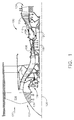
- FIG. 1 is a schematic illustration of an exemplary turbine engine assembly 100 including a fan assembly 102, a low pressure or booster compressor 104, a high-pressure compressor 106, and a combustor 108.
- Fan assembly 102, booster compressor 104, high-pressure compressor 106, and combustor 108 are coupled in flow communication.
- Turbine engine assembly 100 also includes a high-pressure turbine 110 coupled in flow communication with combustor 108 and a low-pressure turbine 112.
- Fan assembly 102 includes an array of fan blades 114 extending radially outward from a rotor disk 116.
- Low-pressure turbine 112 is coupled to fan assembly 102 and booster compressor 104 via a first drive shaft 118, and high-pressure turbine 110 is coupled to high-pressure compressor 106 via a second drive shaft 120.
- Turbine engine assembly 100 has an intake 122 and an exhaust 124.
- Turbine engine assembly 100 further includes a centerline 126 about which fan assembly 102, booster compressor 104, high-pressure compressor 106, and turbine assemblies 110 and 112 rotate.
- a speed-reducing gearbox 128 is coupled along first drive shaft 118 between fan assembly 102 and low-pressure turbine 112.
- air entering turbine engine assembly 100 through intake 122 is channeled through fan assembly 102 towards booster compressor 104.
- Compressed air is discharged from booster compressor 104 towards high-pressure compressor 106.
- Highly compressed air is channeled from high-pressure compressor 106 towards combustor 108, mixed with fuel, and the mixture is combusted within combustor 108.
- High temperature combustion gas generated by combustor 108 is channeled towards turbine assemblies 110 and 112.
- Low-pressure turbine 112 rotates at a first rotational speed, and gearbox 128 operates such that fan assembly 102 operates at a second rotational speed lower than the first rotational speed.
- the second rotational speed is such that a fan tip speed of fan blades 114 is less than about 1,200 feet per second.
- Combustion gas is subsequently discharged from turbine engine assembly 100 via exhaust 124.
- the rotational speeds of low-pressure turbine 112 and fan assembly 102 are decoupled by any mechanism or arrangement of components that enables turbine engine assembly 100 to function as described herein.
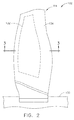
- FIG. 2 is a schematic illustration of fan assembly 102 that may be used with turbine engine assembly 100 (shown in FIG. 1 ), and FIG. 3 is a cross-sectional view of fan blade 114 that may be used with fan assembly 102 taken along line 3-3.
- fan assembly 102 includes fan blade 114 and a fan hub 130 sized to receive fan blades 114.
- turbine engine assembly 100 operates such that low-pressure turbine 112 rotates at a first rotational speed, and such that fan assembly 102 operates at a second rotational speed lower than the first rotational speed.
- Fan blades 114 and fan hub 130 have configurations that are selected based on the rotational speed of fan assembly 102.
- fan blades 114 and fan hub 130 slowing the rotational speed of fan assembly 102 enables fan blades 114 and fan hub 130 to have different configurations than if fan assembly 102 operated at the first rotational speed.
- the configuration of fan blades 114 is selected from a variety of characteristics including at least one of a material used to fabricate fan blade 114, a maximum thickness T max (shown in FIG. 3 ) of fan blade 114, and a mass of fan blade 114.
- fan blades 114 are fabricated at least partially from composite material.
- composite refers to a material including a reinforcement material, such as fibers or particles, supported in a binder or matrix material.
- exemplary composite material includes a carbonaceous (e.g. graphite) fiber embedded in a resin material such as epoxy.
- resin material such as epoxy.
- Prepreg pre-impregnated material
- Prepreg material can be formed into a part shape, and cured via an autoclaving process or press molding process to form a lightweight, rigid, and relatively homogeneous article.
- Fan blade 114 includes a foam core structure 132 and at least one layer 134 of composite material applied to foam core structure 132.
- Foam core structure 132 has a cambered airfoil shape generally corresponding to the shape of fan blade 114.
- Foam core structure 132 is fabricated from a polymeric foam material having a lower density than the composite material.
- An exemplary polymeric foam material includes, but is not limited to, an elastomeric polyurethane foam having a density of about 40% of the density of the composite material. As such, fabricating fan blades 114 from the composite material and polymeric foam material facilitates reducing a weight of fan assembly 102 by up to about 20%.
- fan blades 114 having reduced strength and impact resistance, when compared to metallic fan blades, to be utilized.
- fan blades 114 are fabricated from a metallic material having a reduced size when compared to fan blades utilized if fan assembly 102 operated at the first rotational speed.
- maximum thickness T max is defined between a pressure side 136 and a suction side 138 of fan blade 114, and is defined as the thickest portion of fan blade 114.
- Fan blades 114 having a greater relative maximum thickness T max facilitate disturbing a flow of air channeled through fan assembly 102, which reduces engine performance. As such, operating fan assembly 102 at the slower second rotational speed enables fan blades 114 to be manufactured at a reduced size and, more specifically, with a reduced maximum thickness T max to facilitate unobstructing the flow of air channeled through fan assembly 102.
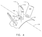
- FIG. 4 is a schematic illustration of a coupling arrangement 140 for fan assembly 102 that may be used with turbine engine assembly 100 (shown in FIG. 1 ).
- fan assembly 102 includes the array of fan blades 114 and a fan hub 142 sized to receive fan blades 114. More specifically, fan blades 114 include an airfoil 144, and are coupled to fan hub 142 via coupling arrangement 140.
- Coupling arrangement 140 includes a coupling member 146 extending from airfoil 144, and a plurality of openings 148 spaced apart at different circumferential locations about fan hub 142.
- Openings 148 are sized to receive at least a portion of coupling member 146, and are sized such that fan blades 114 are allowed to freely rotate therein. Moreover, fan blades 114 extend substantially coaxially along a radial axis 150 extending from fan hub 142. Coupling members 146 are coupled to an actuating mechanism (not shown) that facilitates selectively rotating fan blades 114 about radial axis 150 to modify a pitch of fan blades 114.
- operating fan assembly 102 at the slower second rotational speed enables lighter weight fan blades 114 to be utilized than if fan assembly 102 operated at the first rotational speed.
- Utilizing lighter weight fan blades 114 reduces an amount of centrifugal loading induced on fan hub 142 by fan blades 114 during operation of turbine engine assembly 100.
- an actuatable and more complex coupling arrangement between fan hub 142 and fan blades 114, such as coupling arrangement 140 may be used when compared to a standard dovetail coupling mechanism for use with a fixed pitch blade, for example.
- the turbine engine assembly and methods described herein relate to turbine engines, such as turbofans, that leverage a low-speed fan assembly to enable the use of fan blades with characteristics that facilitate improving engine performance.
- the fan assembly is configured to rotate at a lower rotational speed than a low-pressure turbine. Reducing the rotational speed of the fan assembly reduces strength and impact resistance requirements of the fan blades, which enables the fan blades to be manufactured from light-weight materials, for example.
- a configuration of the fan assembly can be enhanced to improve engine performance.
Landscapes
- Engineering & Computer Science (AREA)
- Mechanical Engineering (AREA)
- General Engineering & Computer Science (AREA)
- Chemical & Material Sciences (AREA)
- Combustion & Propulsion (AREA)
- Materials Engineering (AREA)
- Composite Materials (AREA)
- Structures Of Non-Positive Displacement Pumps (AREA)
- Laminated Bodies (AREA)
Abstract
A turbine engine assembly 100 is provided. The assembly includes a low-pressure turbine 112 configured to rotate at a first rotational speed, and a fan assembly 102 coupled to the low-pressure turbine and configured to rotate at a second rotational speed lower than the first rotational speed. The fan assembly includes a fan blade 114 fabricated from a composite material and having a configuration selected based on the second rotational speed of the fan assembly.
Description
- The present disclosure relates generally to turbine engines and, more specifically, to a turbofan having a reduced fan tip speed, which enables an improved fan assembly architecture to be utilized.
- At least some known gas turbine engines, such as turbofans, include a fan, a core engine, and a power turbine. The core engine includes at least one compressor, a combustor, and a high-pressure turbine coupled together in a serial flow relationship. More specifically, the compressor and high-pressure turbine are coupled through a shaft to form a high-pressure rotor assembly. Air entering the core engine is mixed with fuel and ignited to form a high energy gas stream. The high energy gas stream flows through the high-pressure turbine to rotatably drive the high-pressure turbine such that the shaft rotatably drives the compressor. The gas stream expands as it flows through a power or low-pressure turbine positioned aft of the high-pressure turbine. The low-pressure turbine includes a rotor assembly having a fan coupled to a drive shaft. The low-pressure turbine rotatably drives the fan through the drive shaft.
- Many modem commercial turbofans are manufactured with increasingly large bypass ratios to facilitate improving engine efficiency. However, increasing the bypass ratio of the turbofan results in an increased fan size and fan tip speed. Fan blades in turbofans having relatively large bypass ratios are generally manufactured from a metallic material to ensure the fan blades have sufficient strength to withstand foreign object impacts at the increased fan tip speeds, for example. Fan blades manufactured from metallic material are generally heavy and increase the weight of a turbine engine. At least some known fan blades are manufactured from composite material, such as carbon fiber reinforced polymer. However, fan blades manufactured from composite material generally have reduced strength and impact resistance when compared to metallic counterparts. Therefore, it is desired to have a turbofan architecture than can accommodate non-metallic fan blades.
- In one aspect, a turbine engine assembly is provided. The assembly includes a low-pressure turbine configured to rotate at a first rotational speed, and a fan assembly coupled to the low-pressure turbine and configured to rotate at a second rotational speed lower than the first rotational speed. The fan assembly includes a fan blade fabricated from a composite material and having a configuration selected based on the second rotational speed of the fan assembly.
- In another aspect, a turbine engine assembly is provided. The assembly includes a low-pressure turbine configured to rotate at a first rotational speed, and a drive shaft including a first portion and a second portion. The first portion is coupled to the low-pressure turbine. The assembly also includes a fan assembly coupled to a second portion of the drive shaft, and a gearbox coupled along the drive shaft between the first and second portions such that the fan assembly is configured to rotate at a second rotational speed lower than the first rotational speed. The fan assembly includes a fan blade having a configuration selected based on the second rotational speed of the fan assembly.
- In yet another aspect, a method of manufacturing a turbine engine assembly is provided. The method includes coupling a low-pressure turbine to a first portion of a drive shaft, wherein the low-pressure turbine is configured to rotate at a first rotational speed. The method also includes coupling a fan assembly including a fan blade to a second portion of the drive shaft, coupling a gearbox along the drive shaft between the first and second portions such that the fan assembly is configured to rotate at a second rotational speed lower than the first rotational speed, and selecting a configuration of the fan blade based on the second rotational speed of the fan assembly.
- These and other features, aspects, and advantages of the present disclosure will become better understood when the following detailed description is read with reference to the accompanying drawings in which like characters represent like parts throughout the drawings, wherein:
-
FIG. 1 is a schematic illustration of an exemplary turbine engine assembly. -
FIG. 2 is a schematic illustration of an exemplary fan assembly that may be used with the turbine engine assembly shown inFIG. 1 . -
FIG. 3 is a cross-sectional view of a fan blade that may be used with the fan assembly shown inFIG. 2 taken along line 3-3. -
FIG. 4 is a schematic illustration of an alternative fan assembly that may be used with the turbine engine assembly shown inFIG. 1 . - Unless otherwise indicated, the drawings provided herein are meant to illustrate features of embodiments of the disclosure. These features are believed to be applicable in a wide variety of systems comprising one or more embodiments of the disclosure. As such, the drawings are not meant to include all conventional features known by those of ordinary skill in the art to be required for the practice of the embodiments disclosed herein.
- Embodiments of the present disclosure relate to turbine engines, such as turbofans, and methods of manufacturing thereof. More specifically, the turbine engines described herein include a low-pressure turbine operating at a first rotational speed and a gearbox coupled to a drive shaft extending from the low-pressure turbine. The drive shaft is coupled between the low-pressure turbine and a fan assembly, and the gearbox decouples the rotational speed of the fan assembly from the low-pressure turbine such that the fan assembly rotates at a second rotational speed lower than the first rotational speed. Reducing the rotational speed of the fan assembly enables a configuration of the fan assembly to be modified to enhance performance of the turbine engine. For example, reducing the rotational speed of the fan assembly enables fan blades of the turbofan to be manufactured from composite material, which facilitates reducing the weight of the turbofan and facilitates reducing centrifugal loading at connections between the fan blades and a fan hub during operation. As such, further modifications to the fan assembly, such as utilizing variable pitch fan blades, can be implemented to enhance turbine engine performance and increase component architecture options for the turbine engine.
- As used herein, the terms "axial" and "axially" refer to directions and orientations that extend substantially parallel to a centerline of the turbine engine. Moreover, the terms "radial" and "radially" refer to directions and orientations that extend substantially perpendicular to the centerline of the turbine engine. In addition, as used herein, the terms "circumferential" and "circumferentially" refer to directions and orientations that extend arcuately about the centerline of the turbine engine. It should also be appreciated that the term "fluid" as used herein includes any medium or material that flows, including, but not limited to, air, gas, liquid and steam.
-
FIG. 1 is a schematic illustration of an exemplaryturbine engine assembly 100 including afan assembly 102, a low pressure or booster compressor 104, a high-pressure compressor 106, and acombustor 108.Fan assembly 102, booster compressor 104, high-pressure compressor 106, andcombustor 108 are coupled in flow communication.Turbine engine assembly 100 also includes a high-pressure turbine 110 coupled in flow communication withcombustor 108 and a low-pressure turbine 112.Fan assembly 102 includes an array offan blades 114 extending radially outward from arotor disk 116. Low-pressure turbine 112 is coupled tofan assembly 102 and booster compressor 104 via afirst drive shaft 118, and high-pressure turbine 110 is coupled to high-pressure compressor 106 via asecond drive shaft 120.Turbine engine assembly 100 has anintake 122 and anexhaust 124.Turbine engine assembly 100 further includes acenterline 126 about whichfan assembly 102, booster compressor 104, high-pressure compressor 106, andturbine assemblies gearbox 128 is coupled alongfirst drive shaft 118 betweenfan assembly 102 and low-pressure turbine 112. - In operation, air entering
turbine engine assembly 100 throughintake 122 is channeled throughfan assembly 102 towards booster compressor 104. Compressed air is discharged from booster compressor 104 towards high-pressure compressor 106. Highly compressed air is channeled from high-pressure compressor 106 towardscombustor 108, mixed with fuel, and the mixture is combusted withincombustor 108. High temperature combustion gas generated bycombustor 108 is channeled towardsturbine assemblies pressure turbine 112 rotates at a first rotational speed, andgearbox 128 operates such thatfan assembly 102 operates at a second rotational speed lower than the first rotational speed. In one embodiment, the second rotational speed is such that a fan tip speed offan blades 114 is less than about 1,200 feet per second. Combustion gas is subsequently discharged fromturbine engine assembly 100 viaexhaust 124. In an alternative embodiment, the rotational speeds of low-pressure turbine 112 andfan assembly 102 are decoupled by any mechanism or arrangement of components that enablesturbine engine assembly 100 to function as described herein. -
FIG. 2 is a schematic illustration offan assembly 102 that may be used with turbine engine assembly 100 (shown inFIG. 1 ), andFIG. 3 is a cross-sectional view offan blade 114 that may be used withfan assembly 102 taken along line 3-3. In the exemplary embodiment,fan assembly 102 includesfan blade 114 and afan hub 130 sized to receivefan blades 114. As described above,turbine engine assembly 100 operates such that low-pressure turbine 112 rotates at a first rotational speed, and such thatfan assembly 102 operates at a second rotational speed lower than the first rotational speed.Fan blades 114 andfan hub 130 have configurations that are selected based on the rotational speed offan assembly 102. More specifically, slowing the rotational speed offan assembly 102 enablesfan blades 114 andfan hub 130 to have different configurations than iffan assembly 102 operated at the first rotational speed. For example, the configuration offan blades 114 is selected from a variety of characteristics including at least one of a material used to fabricatefan blade 114, a maximum thickness Tmax (shown inFIG. 3 ) offan blade 114, and a mass offan blade 114. - In one embodiment,
fan blades 114 are fabricated at least partially from composite material. As used herein, the term "composite" refers to a material including a reinforcement material, such as fibers or particles, supported in a binder or matrix material. Exemplary composite material includes a carbonaceous (e.g. graphite) fiber embedded in a resin material such as epoxy. At least some composite materials are commercially available and include fibers unidirectionally aligned in a sheet impregnated with a resin, forming a pre-impregnated material (i.e. "prepreg"). Prepreg material can be formed into a part shape, and cured via an autoclaving process or press molding process to form a lightweight, rigid, and relatively homogeneous article. -
Fan blade 114 includes afoam core structure 132 and at least onelayer 134 of composite material applied tofoam core structure 132.Foam core structure 132 has a cambered airfoil shape generally corresponding to the shape offan blade 114.Foam core structure 132 is fabricated from a polymeric foam material having a lower density than the composite material. An exemplary polymeric foam material includes, but is not limited to, an elastomeric polyurethane foam having a density of about 40% of the density of the composite material. As such, fabricatingfan blades 114 from the composite material and polymeric foam material facilitates reducing a weight offan assembly 102 by up to about 20%. Moreover, operatingfan assembly 102 at the slower second rotational speed enablesfan blades 114 having reduced strength and impact resistance, when compared to metallic fan blades, to be utilized. In an alternative embodiment,fan blades 114 are fabricated from a metallic material having a reduced size when compared to fan blades utilized iffan assembly 102 operated at the first rotational speed. - Referring to
FIG. 3 , in the exemplary embodiment, maximum thickness Tmax is defined between apressure side 136 and asuction side 138 offan blade 114, and is defined as the thickest portion offan blade 114.Fan blades 114 having a greater relative maximum thickness Tmax facilitate disturbing a flow of air channeled throughfan assembly 102, which reduces engine performance. As such, operatingfan assembly 102 at the slower second rotational speed enablesfan blades 114 to be manufactured at a reduced size and, more specifically, with a reduced maximum thickness Tmax to facilitate unobstructing the flow of air channeled throughfan assembly 102. -
FIG. 4 is a schematic illustration of acoupling arrangement 140 forfan assembly 102 that may be used with turbine engine assembly 100 (shown inFIG. 1 ). In the exemplary embodiment,fan assembly 102 includes the array offan blades 114 and afan hub 142 sized to receivefan blades 114. More specifically,fan blades 114 include anairfoil 144, and are coupled tofan hub 142 viacoupling arrangement 140. Couplingarrangement 140 includes acoupling member 146 extending fromairfoil 144, and a plurality ofopenings 148 spaced apart at different circumferential locations aboutfan hub 142.Openings 148 are sized to receive at least a portion ofcoupling member 146, and are sized such thatfan blades 114 are allowed to freely rotate therein. Moreover,fan blades 114 extend substantially coaxially along aradial axis 150 extending fromfan hub 142. Couplingmembers 146 are coupled to an actuating mechanism (not shown) that facilitates selectively rotatingfan blades 114 aboutradial axis 150 to modify a pitch offan blades 114. - As described above, operating
fan assembly 102 at the slower second rotational speed enables lighterweight fan blades 114 to be utilized than iffan assembly 102 operated at the first rotational speed. Utilizing lighterweight fan blades 114 reduces an amount of centrifugal loading induced onfan hub 142 byfan blades 114 during operation ofturbine engine assembly 100. As such, an actuatable and more complex coupling arrangement betweenfan hub 142 andfan blades 114, such ascoupling arrangement 140, may be used when compared to a standard dovetail coupling mechanism for use with a fixed pitch blade, for example. - The turbine engine assembly and methods described herein relate to turbine engines, such as turbofans, that leverage a low-speed fan assembly to enable the use of fan blades with characteristics that facilitate improving engine performance. For example, the fan assembly is configured to rotate at a lower rotational speed than a low-pressure turbine. Reducing the rotational speed of the fan assembly reduces strength and impact resistance requirements of the fan blades, which enables the fan blades to be manufactured from light-weight materials, for example. Moreover, a configuration of the fan assembly can be enhanced to improve engine performance.
- Although specific features of various embodiments of the present disclosure may be shown in some drawings and not in others, this is for convenience only. In accordance with the principles of embodiments of the present disclosure, any feature of a drawing may be referenced and/or claimed in combination with any feature of any other drawing.
- This written description uses examples to disclose the embodiments of the present disclosure, including the best mode, and also to enable any person skilled in the art to practice embodiments of the present disclosure, including making and using any devices or systems and performing any incorporated methods. The patentable scope of the embodiments described herein is defined by the claims, and may include other examples that occur to those skilled in the art. Such other examples are intended to be within the scope of the claims if they have structural elements that do not differ from the literal language of the claims, or if they include equivalent structural elements with insubstantial differences from the literal languages of the claims.
- Various aspects and embodiments of the present invention are defined by the following numbered clauses:
- 1. A turbine engine assembly comprising:
- a low-pressure turbine configured to rotate at a first rotational speed; and
- a fan assembly coupled to said low-pressure turbine and configured to rotate at a second rotational speed lower than the first rotational speed, wherein said fan assembly comprises a fan blade fabricated from a composite material and having a configuration selected based on the second rotational speed of said fan assembly.
- 2. The turbine engine assembly in accordance with clause 1 further comprising:
- a drive shaft coupled between said low-pressure turbine and said fan assembly; and
- a gearbox coupled along said drive shaft such that said fan assembly rotates at the second rotational speed when the low-pressure turbine is rotating at the first rotational speed.
- 3. The turbine engine assembly in accordance with any preceding clause, wherein the configuration of said fan blade is selected from characteristics including at least one of a maximum thickness of said fan blade, and a mass of said fan blade.
- 4. The turbine engine assembly in accordance with any preceding clause, wherein the mass of said fan blade is lower than if said fan assembly were configured to rotate at the first rotational speed.
- 5. The turbine engine assembly in accordance with any preceding clause, wherein said fan blade comprises:
- a foam core structure; and
- at least one layer of the composite material applied to said foam core structure.
- 6. The turbine engine assembly in accordance with any preceding clause, wherein said fan assembly is configured to rotate at the second rotational speed such that a fan tip speed of said fan blade is less than about 1,200 feet per second.
- 7. The turbine engine assembly in accordance with any preceding clause, wherein said fan assembly comprises a fan hub configured to receive said fan blade, said fan blade configured to selectively rotate about a radial axis extending from said fan hub.
- 8. A turbine engine assembly comprising:
- a low-pressure turbine configured to rotate at a first rotational speed;
- a drive shaft comprising a first portion and a second portion, said first portion coupled to said low-pressure turbine;
- a fan assembly coupled to said second portion of said drive shaft; and
- a gearbox coupled along said drive shaft between said first and second portions such that said fan assembly is configured to rotate at a second rotational speed lower than the first rotational speed, wherein said fan assembly comprises a fan blade having a configuration selected based on the second rotational speed of said fan assembly.
- 9. The turbine engine assembly in accordance with any preceding clause, wherein the configuration of said fan blade is selected from characteristics including at least one of a material used to fabricate said fan blade, a maximum thickness of said fan blade, and a mass of said fan blade.
- 10. The turbine engine assembly in accordance with any preceding clause, wherein the mass of said fan blade is lower than if said fan assembly were configured to rotate at the first rotational speed.
- 11. The turbine engine assembly in accordance with any preceding clause, wherein said fan blade is fabricated from a composite material.
- 12. The turbine engine assembly in accordance with any preceding clause, wherein said fan blade comprises:
- a foam core structure; and
- at least one layer of a composite material applied to said foam core structure.
- 13. The turbine engine assembly in accordance with any preceding clause, wherein said fan assembly is configured to rotate at the second rotational speed such that a fan tip speed of said fan blade is less than about 1,200 feet per second.
- 14. The turbine engine assembly in accordance with any preceding clause, wherein said fan assembly comprises a fan hub configured to receive said fan blade, said fan blade configured to selectively rotate about a radial axis extending from said fan hub.
- 15. A method of manufacturing a turbine engine assembly, said method comprising:
- coupling a low-pressure turbine to a first portion of a drive shaft, wherein the low-pressure turbine is configured to rotate at a first rotational speed;
- coupling a fan assembly comprising a fan blade to a second portion of the drive shaft;
- coupling a gearbox along the drive shaft between the first and second portions such that the fan assembly is configured to rotate at a second rotational speed lower than the first rotational speed; and
- selecting a configuration of the fan blade based on the second rotational speed of the fan assembly.
- 16. The method in accordance with any preceding clause, wherein selecting a configuration of the fan blade comprises selecting the configuration of the fan blade from characteristics including at least one of a material used to fabricate said fan blade, a maximum thickness of the fan blade, and a mass of the fan blade.
- 17. The method in accordance with any preceding clause, wherein selecting a configuration comprises:
- determining a first mass of the fan blade when the fan assembly is configured to rotate at the first rotational speed; and
- reducing the mass of the fan blade from the first mass to a second mass based on the second rotational speed of the fan assembly.
- 18. The method in accordance with any preceding clause, wherein selecting a configuration comprises fabricating the fan blade from a composite material.
- 19. The method in accordance with any preceding clause further comprising configuring the fan assembly to rotate at the second rotational speed such that a fan tip speed of the fan blade is less than about 1,200 feet per second.
- 20. The method in accordance with any preceding clause, wherein coupling a fan assembly comprises sizing at least a portion of the fan blade for insertion within a fan hub, the fan blade configured to selectively rotate about a radial axis extending from the fan hub.
Claims (15)
- A turbine engine assembly (100) comprising:a low-pressure turbine (112) configured to rotate at a first rotational speed; anda fan assembly (102) coupled to said low-pressure turbine and configured to rotate at a second rotational speed lower than the first rotational speed, wherein said fan assembly comprises a fan blade (114) fabricated from a composite material and having a configuration selected based on the second rotational speed of said fan assembly.
- The turbine engine assembly (100) in accordance with claim 1, further comprising:a drive shaft (118) coupled between said low-pressure turbine (112) and said fan assembly (102); anda gearbox (128) coupled along said drive shaft (118) such that said fan assembly (102) rotates at the second rotational speed when the low-pressure turbine is rotating at the first rotational speed.
- The turbine engine assembly (100) in accordance with either of claims 1 or 2, wherein the configuration of said fan blade (114) is selected from characteristics including at least one of a maximum thickness of said fan blade, and a mass of said fan blade.
- The turbine engine assembly (100) in accordance with claim 3, wherein the mass of said fan blade (114) is lower than if said fan assembly (102) were configured to rotate at the first rotational speed.
- The turbine engine assembly (100) in accordance with any preceding claim, wherein said fan blade (114) comprises:a foam core structure (132); andat least one layer (134) of the composite material applied to said foam core structure.
- The turbine engine assembly (100) in accordance with any preceding claim, wherein said fan assembly (102) is configured to rotate at the second rotational speed such that a fan tip speed of said fan blade (114) is less than about 1,200 feet per second.
- The turbine engine assembly (100) in accordance with any preceding claim, wherein said fan assembly (102) comprises a fan hub configured to receive said fan blade (114), said fan blade configured to selectively rotate about a radial axis extending from said fan hub.
- A turbine engine assembly (100) in accordance with any of the preceding claims, the assembly further comprising:a drive shaft (118) comprising a first portion and a second portion, said first portion coupled to said low-pressure turbine (112);the fan assembly (102) coupled to said second portion of said drive shaft (118); anda gearbox (128) coupled along said drive shaft between said first and second portions such that said fan assembly (102) is configured to rotate at the second rotational speed lower than the first rotational speed.
- The turbine engine assembly (100) of any of the preceding claims, wherein the fan blade (114) is fabricated from a composite material.
- The turbine engine assembly (100) in accordance with either of claims 8 or 9, wherein the configuration of said fan blade (114) is selected from characteristics including at least one of a material used to fabricate said fan blade, a maximum thickness of said fan blade, and a mass of said fan blade.
- The turbine engine assembly (100) in accordance with any of claims 8 to 10, wherein said fan assembly (102) is configured to rotate at the second rotational speed such that a fan tip speed of said fan blade (114) is less than about 1,200 feet per second.
- A method of manufacturing a turbine engine assembly (100), said method comprising:coupling a low-pressure turbine (112) to a first portion of a drive shaft, wherein the low-pressure turbine is configured to rotate at a first rotational speed;coupling a fan assembly (102) comprising a fan blade (114) to a second portion of the drive shaft (118);coupling a gearbox (128) along the drive shaft between the first and second portions such that the fan assembly (102) is configured to rotate at a second rotational speed lower than the first rotational speed; andselecting a configuration of the fan blade (114) based on the second rotational speed of the fan assembly (102).
- The method in accordance with claim 12, wherein selecting a configuration of the fan blade (114) comprises selecting the configuration of the fan blade from characteristics including at least one of a material used to fabricate said fan blade, a maximum thickness of the fan blade, and a mass of the fan blade.
- The method in accordance with claim 13, wherein selecting a configuration comprises fabricating the fan blade (114) from a composite material and/or
determining a first mass of the fan blade when the fan assembly (102) is configured to rotate at the first rotational speed; and
reducing the mass of the fan blade (114) from the first mass to a second mass based on the second rotational speed of the fan assembly. - The method in accordance with any of claims 12 to 14, further comprising configuring the fan assembly (102) to rotate at the second rotational speed such that a fan tip speed of the fan blade (114) is less than about 1,200 feet per second.
Applications Claiming Priority (2)
| Application Number | Priority Date | Filing Date | Title |
|---|---|---|---|
| US201462082634P | 2014-11-21 | 2014-11-21 | |
| US14/873,357 US20160186657A1 (en) | 2014-11-21 | 2015-10-02 | Turbine engine assembly and method of manufacturing thereof |
Publications (1)
| Publication Number | Publication Date |
|---|---|
| EP3023602A1 true EP3023602A1 (en) | 2016-05-25 |
Family
ID=54695590
Family Applications (1)
| Application Number | Title | Priority Date | Filing Date |
|---|---|---|---|
| EP15195693.5A Withdrawn EP3023602A1 (en) | 2014-11-21 | 2015-11-20 | Turbine engine assembly and corresponding manufacturing method |
Country Status (6)
| Country | Link |
|---|---|
| US (1) | US20160186657A1 (en) |
| EP (1) | EP3023602A1 (en) |
| JP (1) | JP2016138545A (en) |
| CN (1) | CN105864100A (en) |
| BR (1) | BR102015029071A2 (en) |
| CA (1) | CA2912399A1 (en) |
Families Citing this family (4)
| Publication number | Priority date | Publication date | Assignee | Title |
|---|---|---|---|---|
| US10711693B2 (en) * | 2017-07-12 | 2020-07-14 | General Electric Company | Gas turbine engine with an engine rotor element turning device |
| JP6738850B2 (en) * | 2018-03-29 | 2020-08-12 | 三菱重工業株式会社 | Composite material blade and method of manufacturing composite material blade |
| CN112833040B (en) * | 2021-03-18 | 2022-08-02 | 王智瀚 | Split electric fan |
| US12601271B2 (en) | 2022-10-21 | 2026-04-14 | General Electric Company | Variable pitch fan of a gas turbine engine |
Citations (6)
| Publication number | Priority date | Publication date | Assignee | Title |
|---|---|---|---|---|
| EP2189627A1 (en) * | 2008-11-25 | 2010-05-26 | Rolls-Royce Deutschland Ltd & Co KG | Method for the manufacture of hybrid components for aircraft gas turbines |
| EP2243929A2 (en) * | 2009-04-16 | 2010-10-27 | United Technologies Corporation | Hybrid structure fan blade |
| EP2353830A2 (en) * | 2010-02-05 | 2011-08-10 | United Technologies Corporation | Method of manufacturing a composite fan blade with co-cured sheath, and corresponding fan blade |
| US8678743B1 (en) * | 2013-02-04 | 2014-03-25 | United Technologies Corporation | Method for setting a gear ratio of a fan drive gear system of a gas turbine engine |
| WO2014055113A1 (en) * | 2012-10-01 | 2014-04-10 | United Technologies Corporation | Geared turbofan with high fan rotor power intensity |
| WO2014143305A1 (en) * | 2013-03-14 | 2014-09-18 | United Technologies Corporation | Low speed fan for gas turbine engines |
Family Cites Families (8)
| Publication number | Priority date | Publication date | Assignee | Title |
|---|---|---|---|---|
| CN1204005A (en) * | 1997-06-26 | 1999-01-06 | 亚瑞亚·勃朗勃威力有限公司 | Jet engine |
| US7752836B2 (en) * | 2005-10-19 | 2010-07-13 | General Electric Company | Gas turbine assembly and methods of assembling same |
| FR2940818B1 (en) * | 2009-01-07 | 2011-03-11 | Airbus France | AIRCRAFT TURBOMOTEUR AND USE OF THIS TURBOMOTEUR |
| WO2013141930A1 (en) * | 2011-12-30 | 2013-09-26 | United Technologies Corporation | Gas turbine engine with low fan pressure ratio |
| US8246292B1 (en) * | 2012-01-31 | 2012-08-21 | United Technologies Corporation | Low noise turbine for geared turbofan engine |
| US9416668B2 (en) * | 2012-04-30 | 2016-08-16 | United Technologies Corporation | Hollow fan bladed with braided fabric tubes |
| KR101740327B1 (en) * | 2012-11-22 | 2017-06-08 | 한국전자통신연구원 | Apparatus and system for providing software service using software virtualization and method thereof |
| US9453418B2 (en) * | 2012-12-17 | 2016-09-27 | United Technologies Corporation | Hollow airfoil with composite cover and foam filler |
-
2015
- 2015-10-02 US US14/873,357 patent/US20160186657A1/en not_active Abandoned
- 2015-11-19 JP JP2015226189A patent/JP2016138545A/en active Pending
- 2015-11-19 CA CA2912399A patent/CA2912399A1/en not_active Abandoned
- 2015-11-19 BR BR102015029071A patent/BR102015029071A2/en not_active Application Discontinuation
- 2015-11-20 EP EP15195693.5A patent/EP3023602A1/en not_active Withdrawn
- 2015-11-20 CN CN201511036172.5A patent/CN105864100A/en active Pending
Patent Citations (6)
| Publication number | Priority date | Publication date | Assignee | Title |
|---|---|---|---|---|
| EP2189627A1 (en) * | 2008-11-25 | 2010-05-26 | Rolls-Royce Deutschland Ltd & Co KG | Method for the manufacture of hybrid components for aircraft gas turbines |
| EP2243929A2 (en) * | 2009-04-16 | 2010-10-27 | United Technologies Corporation | Hybrid structure fan blade |
| EP2353830A2 (en) * | 2010-02-05 | 2011-08-10 | United Technologies Corporation | Method of manufacturing a composite fan blade with co-cured sheath, and corresponding fan blade |
| WO2014055113A1 (en) * | 2012-10-01 | 2014-04-10 | United Technologies Corporation | Geared turbofan with high fan rotor power intensity |
| US8678743B1 (en) * | 2013-02-04 | 2014-03-25 | United Technologies Corporation | Method for setting a gear ratio of a fan drive gear system of a gas turbine engine |
| WO2014143305A1 (en) * | 2013-03-14 | 2014-09-18 | United Technologies Corporation | Low speed fan for gas turbine engines |
Also Published As
| Publication number | Publication date |
|---|---|
| CA2912399A1 (en) | 2016-05-21 |
| BR102015029071A2 (en) | 2016-08-09 |
| CN105864100A (en) | 2016-08-17 |
| US20160186657A1 (en) | 2016-06-30 |
| JP2016138545A (en) | 2016-08-04 |
Similar Documents
| Publication | Publication Date | Title |
|---|---|---|
| CN107044445B (en) | Fragile gas turbine engine airfoils | |
| US8061966B2 (en) | Composite containment casings | |
| US8046915B2 (en) | Methods for making composite containment casings | |
| US8371009B2 (en) | Methods for repairing composite containment casings | |
| CN112627979B (en) | Containment shell with ceramic coated fibers | |
| US20130202449A1 (en) | Axisymmetric part for an aviation turbine engine rotor | |
| EP3023602A1 (en) | Turbine engine assembly and corresponding manufacturing method | |
| US10287918B2 (en) | Composite attachment structure with 3D weave | |
| US12352174B2 (en) | Fan retention member for supporting a blade platform of a fan assembly | |
| US12601269B2 (en) | Turbine engine with composite airfoils | |
| US12467370B2 (en) | Turbine engine with composite airfoils | |
| CN115126714A (en) | Hybrid composite component | |
| US12320273B2 (en) | Turbine engine with composite airfoils | |
| US10018054B2 (en) | Fabrication of gas turbine engine components using multiple processing steps | |
| CN115111184B (en) | Components formed from hybrid materials | |
| US20240301890A1 (en) | Turbomachine and method of assembly | |
| CN118030310B (en) | Turbine and method of assembly | |
| US20240295224A1 (en) | Turbomachine and method of assembly | |
| CN118482031A (en) | Fan assembly having a fan retention member for supporting a blade platform | |
| CN118257632A (en) | Composite airfoil assembly having dovetail portion | |
| CN117087252A (en) | Composite fan blades and covering methods |
Legal Events
| Date | Code | Title | Description |
|---|---|---|---|
| AK | Designated contracting states |
Kind code of ref document: A1 Designated state(s): AL AT BE BG CH CY CZ DE DK EE ES FI FR GB GR HR HU IE IS IT LI LT LU LV MC MK MT NL NO PL PT RO RS SE SI SK SM TR |
|
| AX | Request for extension of the european patent |
Extension state: BA ME |
|
| PUAI | Public reference made under article 153(3) epc to a published international application that has entered the european phase |
Free format text: ORIGINAL CODE: 0009012 |
|
| STAA | Information on the status of an ep patent application or granted ep patent |
Free format text: STATUS: THE APPLICATION IS DEEMED TO BE WITHDRAWN |
|
| 18D | Application deemed to be withdrawn |
Effective date: 20161126 |