EP3023590A1 - Turbine rotor assembly, blade stop plate for turbine rotor assembly, and method for assembling blade stop plate - Google Patents
Turbine rotor assembly, blade stop plate for turbine rotor assembly, and method for assembling blade stop plate Download PDFInfo
- Publication number
- EP3023590A1 EP3023590A1 EP14864540.1A EP14864540A EP3023590A1 EP 3023590 A1 EP3023590 A1 EP 3023590A1 EP 14864540 A EP14864540 A EP 14864540A EP 3023590 A1 EP3023590 A1 EP 3023590A1
- Authority
- EP
- European Patent Office
- Prior art keywords
- blade
- rotor
- axial
- inward
- outward
- Prior art date
- Legal status (The legal status is an assumption and is not a legal conclusion. Google has not performed a legal analysis and makes no representation as to the accuracy of the status listed.)
- Withdrawn
Links
- 238000000034 method Methods 0.000 title claims description 12
- 238000005452 bending Methods 0.000 claims description 10
- 239000012530 fluid Substances 0.000 claims description 4
- 238000011144 upstream manufacturing Methods 0.000 description 4
- 230000000694 effects Effects 0.000 description 3
- 238000003780 insertion Methods 0.000 description 2
- 230000037431 insertion Effects 0.000 description 2
- 238000004519 manufacturing process Methods 0.000 description 2
- 238000012423 maintenance Methods 0.000 description 1
- 239000000463 material Substances 0.000 description 1
- 230000010355 oscillation Effects 0.000 description 1
- 230000002093 peripheral effect Effects 0.000 description 1
Images



Classifications
-
- F—MECHANICAL ENGINEERING; LIGHTING; HEATING; WEAPONS; BLASTING
- F01—MACHINES OR ENGINES IN GENERAL; ENGINE PLANTS IN GENERAL; STEAM ENGINES
- F01D—NON-POSITIVE DISPLACEMENT MACHINES OR ENGINES, e.g. STEAM TURBINES
- F01D5/00—Blades; Blade-carrying members; Heating, heat-insulating, cooling or antivibration means on the blades or the members
- F01D5/30—Fixing blades to rotors; Blade roots ; Blade spacers
- F01D5/32—Locking, e.g. by final locking blades or keys
- F01D5/323—Locking of axial insertion type blades by means of a key or the like parallel to the axis of the rotor
-
- F—MECHANICAL ENGINEERING; LIGHTING; HEATING; WEAPONS; BLASTING
- F01—MACHINES OR ENGINES IN GENERAL; ENGINE PLANTS IN GENERAL; STEAM ENGINES
- F01D—NON-POSITIVE DISPLACEMENT MACHINES OR ENGINES, e.g. STEAM TURBINES
- F01D5/00—Blades; Blade-carrying members; Heating, heat-insulating, cooling or antivibration means on the blades or the members
- F01D5/30—Fixing blades to rotors; Blade roots ; Blade spacers
-
- F—MECHANICAL ENGINEERING; LIGHTING; HEATING; WEAPONS; BLASTING
- F01—MACHINES OR ENGINES IN GENERAL; ENGINE PLANTS IN GENERAL; STEAM ENGINES
- F01D—NON-POSITIVE DISPLACEMENT MACHINES OR ENGINES, e.g. STEAM TURBINES
- F01D5/00—Blades; Blade-carrying members; Heating, heat-insulating, cooling or antivibration means on the blades or the members
- F01D5/30—Fixing blades to rotors; Blade roots ; Blade spacers
- F01D5/3007—Fixing blades to rotors; Blade roots ; Blade spacers of axial insertion type
-
- F—MECHANICAL ENGINEERING; LIGHTING; HEATING; WEAPONS; BLASTING
- F01—MACHINES OR ENGINES IN GENERAL; ENGINE PLANTS IN GENERAL; STEAM ENGINES
- F01D—NON-POSITIVE DISPLACEMENT MACHINES OR ENGINES, e.g. STEAM TURBINES
- F01D5/00—Blades; Blade-carrying members; Heating, heat-insulating, cooling or antivibration means on the blades or the members
- F01D5/30—Fixing blades to rotors; Blade roots ; Blade spacers
- F01D5/3007—Fixing blades to rotors; Blade roots ; Blade spacers of axial insertion type
- F01D5/3015—Fixing blades to rotors; Blade roots ; Blade spacers of axial insertion type with side plates
-
- F—MECHANICAL ENGINEERING; LIGHTING; HEATING; WEAPONS; BLASTING
- F05—INDEXING SCHEMES RELATING TO ENGINES OR PUMPS IN VARIOUS SUBCLASSES OF CLASSES F01-F04
- F05D—INDEXING SCHEME FOR ASPECTS RELATING TO NON-POSITIVE-DISPLACEMENT MACHINES OR ENGINES, GAS-TURBINES OR JET-PROPULSION PLANTS
- F05D2260/00—Function
- F05D2260/96—Preventing, counteracting or reducing vibration or noise
Definitions
- the present disclosure relates to a turbine rotor assembly, a blade stopper for a turbine rotor assembly, and a method of mounting the blade stopper.
- an exterior force is applied to a group of rotor blades in the circumferential direction of a rotor disc via blade roots due to a centrifugal force or oscillation based on rotation of the rotor disc, the rotor blades being attached to axial grooves formed on the rotor disc via the blade roots.
- the group of rotor blades may slide on the axial grooves formed on the rotor disc via the blade roots, and a fixing member (hereinafter, referred to as a blade stopper) is disposed between each blade root and the corresponding one of the axial grooves as a countermeasure to such movement (see, for instance, Patent Document 1).
- the blade stopper herein includes a base section to be fitted into the axial groove and end sections protruding out of the axial groove, the end sections being disposed on the downstream side and the upstream side and bended so that the end sections hold the fitting joint between the blade root and the axial groove from behind. Further, the end sections on the downstream side and the upstream side are facing respective end surfaces of a blade support, the end surfaces being disposed on the opposite outer sides of the blade support, and stoppers are provided to avoid unfolding of the end sections.
- a fixing element is formed integrally with the blade support and disposed adjacently in the axial direction to the first end section of the blade stopper, the fixing element also forming a stopper in the axial direction for the blade stopper. Further, the first end section of the blade stopper is disposed inside the circumferential groove between the stopper and the blade support. The stopper prevents movement of the blade stopper in the axial direction out of the position and unfolding of the end sections due to the generated force, and thus the blade roots and the rotor blades with the blade roots are maintained to be in the accurate positions.
- axial holes are formed through a disc and root portions of rotor blades, and blade stopping pins are inserted into the axial holes, the blade stopping pins having a head with a larger diameter than that of the axial holes and a threaded hole threaded at an end portion. Also, screws with a head larger in diameter than the holes are screwed into the threaded holes of the blade stopping pins. In this way, the rotor blades are supported without gaps and the parts can be repeatedly used in disassembling and assembling the blades.
- Patent Document 1 the structure is inevitably complicated, because the end surfaces of the blade support are disposed on the opposite outer sides of the end sections of the blade stoppers, and the stoppers are provided to avoid unfolding of the end sections.
- Patent Document 2 considerable labor may be required to disassemble or assemble the rotor blades because the structure is such that the rotor blades are supported without gaps and the components can be repeatedly used in disassembling and assembling the blades.
- the blade stopping pins are inserted into the axial holes formed in the axial direction of the disc and fixed by the screws from the opposite side in the direction of insertion of the blade stopping pins so as to prevent the blade stopping pins from falling off.
- An object of at least one embodiment of the present invention is to provide a turbine rotor assembly, a blade stopper for a turbine rotor assembly, and a method of mounting the blade stopper, whereby it is possible to hold a rotor blade in its position with a more simplified structure.
- a turbine rotor assembly comprises: a rotor disc formed with a plurality of axial grooves on an outer periphery of the rotor disc; and a group of rotor blades arranged along a circumferential direction of the rotor disc and engaged with the axial grooves via blade stoppers.
- Each of the blade stoppers comprises: a base section fitted into corresponding one of the axial grooves; and bend sections disposed on opposite ends of the base section so as to protrude from the axial groove in an axial direction, the bend sections being bended in a radial direction of the rotor disc to be in contact with an axial end surface of the rotor disc.
- At least one of the bend sections at the opposite ends comprises an inward-and-outward bend part which protrudes on the axial end surface outward and inward in the radial direction of the rotor disc.
- the blade stopper has end sections protruding from the axial groove in the axial direction, and one of the bend sections bended in the radial direction of the rotor disc to be in contact with the axial end surface of the rotor disc includes the inward-and-outward bend part protruding both inward and outward in the radial direction.
- the inward-and-outward bend part is disposed on at least a downstream side with respect to a flow of working fluid which flows through the group of rotor blades.
- the inward-and-outward bend part is disposed on the downstream side, where the group of blades is affected more greatly by the external force generated by the working fluid. In this way, it is possible to avoid movement of the group of blades in the axial direction out of the position and unfolding of the end sections of the blade stopper.
- the inward-and-outward bend part comprises an outward bend portion and an inward bend portion which are bended outward and inward in the radial direction, respectively, the outward bend portion being formed into a substantially rectangular shape in a rotational-axis directional view, and the inward bend portion forming a protruding portion protruding inward from the outward bend portion.
- the outward bend portion and the inward bend portion of the inward-and-outward bend part are in contact with the axial end surface of the rotor disc, which makes it possible to support the rotor blades suitably against the misalignment force applied to the rotor blades in a larger area.
- a blade stopper is for a turbine rotor assembly comprising: a rotor disc formed with a plurality of axial grooves on an outer periphery of the rotor disc; and a group of rotor blades arranged along a circumferential direction of the rotor disc and engaged with the axial grooves via a plurality of blade stoppers.
- the group of the rotor blades is fixed to the rotor disc via blade roots.
- the blade stopper comprises: a base section configured to be fitted into corresponding one of the axial grooves, the base section having a length corresponding to the axial groove; and a pair of end sections disposed on opposite ends of the base section and configured to be bended at a boundary position to the base section so as to be in contact with an axial end surface of the rotor disc. At least one of the pair of end sections comprises a protrusion protruding inward with respect to the base section from the boundary position between the at least one end section and the base section.
- At least one of the end portions of the blade stopper protruding from the axial groove includes the protrusion protruding inward with respect to the base section from the boundary position between the end section and the base section. In this way, it is possible to maintain the rotor blades sufficiently against the external force applied in the axial direction.
- a method of mounting the blade stopper to the turbine rotor assembly comprises: a first step of forming the inward-and-outward bend part protruding inward and outward by bending one end of the blade stopper outward in the radial direction; a second step of fitting the base section of the blade stopper into the axial groove from above; a third step of inserting a blade root of the rotor blade into the axial groove from a side of the other end of the blade stopper; and a fourth step of bending the other end to fix the rotor blade in the axial groove via the blade stopper.
- the blade stopper has end portions protruding from the axial groove in the axial direction, and one of the bend portions bended in the radial direction of the rotor disc to be in contact with the axial end surface of the rotor disc includes the inward-and-outward bend part protruding both inward and outward in the radial direction.
- a blade stopper which can maintain the rotor blades sufficiently against an external force in the axial direction of the rotor blades.
- FIG 1 illustrates a turbine rotor assembly 1 according to the first embodiment.
- the turbine rotor assembly 1 is to be mounted to an axial-flow turbine, for instance, and includes a rotor disc 2, a plurality of axial grooves 3 (see FIG. 3 ) formed on the outer periphery of the rotor disc 2, and a group 5n of rotor blades arranged along the circumferential direction of the rotor disc 2 and engaged with the axial grooves 3 via blade stoppers 4.
- the rotor disc 2 is a rotational disc which has a predetermined radius and which rotates about an axis of the axial-flow turbine.
- the axial grooves 3 formed on the outer periphery of the rotor disc 2 surround the entire periphery at predetermined intervals and form a predetermined angle with respect to the axial direction.
- the axial grooves 3 are each a groove with stepped walls engraved in a V-shape to have a plurality of steps, the groove widening from a bottom section toward an outer peripheral section of the rotor disc 2, as seen from the end surface of the rotor disc 2 in the axial direction.
- the axial grooves 3 are formed to penetrate through the rotor disc 2, and may be parallel to the axial direction of the rotor disc 2 or may form a predetermined angle with respect to the axial direction of the rotor disc 2.
- the group 5n of rotor blades includes individual rotor blades 5 arranged at regular intervals in the respective axial grooves 3 formed over the entire periphery of the rotor disc 2.
- Each of the rotor blades 5 substantially includes a blade root 51 formed to be capable of being fitted into corresponding one of the axial grooves 3, a platform 52, and a blade portion 53.
- the blade root 51 is formed in a stepped and tapered shape so as to be fitted into the axial groove 3.
- the blade stopper 4 is a thin plate member as illustrated in FIG. 2 , and has a base section 41 to be fitted into a groove portion at the side of the bottom section of the axial groove 3, and a pair of end sections disposed on either end of the base section 41 so as to protrude from the axial groove 3 in the axial direction.
- the pair of end sections of the blade stopper 4 forms bend sections 42, 42 bended outward in the radial direction of the rotor disc 2, which is the radial direction, to contact the respective axial end surfaces of the rotor disc 2.
- the bend sections 42, 42 each have a width dimension larger than that of the base section 41, in a direction intersecting with an axis of the base section 41.
- At least one of the bend sections 42, 42 includes an inward-and-outward bend part (an outward bend portion 42o and an inward bend portion 42i) which protrudes from the base section 41 outward and inward in the radial direction of the rotor disc 2.
- the outward bend portion 42o protrudes from the base section 41 outward in the radial direction of the rotor disc 2, with the blade stopper 4 bended at a bending line at a boundary position between the at least one bend section 42 and the base section 41.
- the inward bend portion 42i protrudes from the base section 41 inward in the radial direction of the rotor disc 2, with the blade stopper 4 bended at a bending line at a boundary position between the at least one bend section 42 and the base section 41.
- the blade stopper 4 has a pair of inward bend portions 42i.
- the base section 41 has a length corresponding to the groove length of the axial groove 3 formed on the rotor disc 2. In other words, the base section 41 has the substantially same dimension as that of the axial groove 3 in the axial direction. Further, the base section 41 and the bend sections 42, 42 at the opposite ends form the same angle as that of the axial groove 3 with respect to the axial direction.
- the blade stopper 4 is attached to one of the axial grooves 3 disposed next to one another on the outer periphery of the rotor disc 2.
- the blade stopper 4 is bended at bending lines between the base section 41 and the bend sections 42 in preparation of mounting the blade stopper 4 to the corresponding axial groove 3.
- the bend section 42 having the outward bend portion 42o and the inward bend portions 42i is bended outward in the radial direction. In this way, the outward bend portion 42o protrudes outward in the radial direction and the inward bend portions 42i protrude inward in the radial direction.
- the base section 41 of the blade stopper 4 is inserted into the axial groove 3 from above to be fitted into the axial groove 3.
- the base section 41 and the axial groove 3 have substantially the same length dimensions, and the axial groove 3 has stepped walls engraved in a V shape to have a plurality of steps.
- the base section 41 can be fitted into the axial groove 3 at a position where the width dimension of the base section 41 is substantially the same as the groove width of the axial groove 3.
- the outward bend portion 42o and the pair of inward bend portions 42i of the bend section 42 are in contact with the axial end surface of the rotor disc 2, which makes it possible to support the axial end surface in a larger area than in a case where only the outward bend portion 42o is in contact.
- the other bend section 42 of the blade stopper 4 is not bended.
- the blade root 51 of the rotor blade 5 is inserted into the axial groove 3 from the side of the non-bended one of the end sections of the blade stopper 4. In this way, it is possible to fit the blade root 51 into the axial groove 3 formed in a stepped and tapered shape while avoiding interference between the blade stopper 4 and the blade root 51 of the rotor blade 5.
- the bend section 42 of the blade stopper 4 not having been bended is finally bended outward in the radial direction.
- the joint between the blade root 51 of the rotor blade 5 and the axial groove 3 is held between both of the bend sections 42, 42 of the blade stopper 4 so as to be capable of sufficiently bearing at least the external force applied in the axial direction of the rotor disc 2 (see FIG. 6 ).
- the present invention can be also implemented according to the second embodiment.
- the blade stopper 4 has end sections protruding from the axial groove 3 in the axial direction, and only one of the bend sections 42 includes the outward bend portion 42o protruding outward in the radial direction and the inward bend portions 42i protruding inward in the radial direction, as in the first embodiment.
- the other bend section which is the bend section 42 to be set on the upstream side in the axial direction of the rotor disc 2, includes the second inward bend portions 42i2 being protrusions protruding in the longitudinal direction of the outward bend portion 42o.
- the second inward bend portions 42i2 are bended inward in the radial direction (see FIG. 8 ) after steps (first to fourth steps) similar to those in the first embodiment are completed.
- the blade stopper 4 before being mounted to the axial groove 3, the blade stopper 4 is bended at a bending line at the boundary between one of the bend sections 42 and the base section 41 (first step), and the blade stopper 4 in this state is inserted into the axial groove 3 from above (second step), the blade root 51 of the rotor blade 5 is inserted and fitted into the axial groove 3 from the side of the non-bended end section of the blade stopper 4 (third step), and the other bend section 42 of the blade stopper 4 not having been bended is now bended outward in the radial direction (fourth step). Then, finally, the second bend portions 42i2 of the other bend section 42 are bended inward in the radial direction.
- the second inward bend portions 42i2 form protrusions protruding inward in the radial direction and contact the axial end surface of the rotor disc 2, so that the joint between the blade root 51 of the rotor blade 5 and the axial groove 3 is held between both of the bend sections 42, 42 of the blade stopper 4, which further improves the effect to prevent misalignment against at least the external force applied in the axial direction of the rotor disc 2 (see FIG 9 ).
- the blade stopper 4 is used so that the bend sections 42, 42 protruding from the axial groove 3 in the axial direction further protrude inward in the radial direction, which makes it possible to sufficiently bear an external force applied to the rotor disc 2 in the axial direction.
- the present invention can be suitably applied not only to a turbine rotor assembly of an axial-flow turbine but also to any rotary machine to secure blades.
Landscapes
- Engineering & Computer Science (AREA)
- Mechanical Engineering (AREA)
- General Engineering & Computer Science (AREA)
- Turbine Rotor Nozzle Sealing (AREA)
- Structures Of Non-Positive Displacement Pumps (AREA)
Abstract
Description
- The present disclosure relates to a turbine rotor assembly, a blade stopper for a turbine rotor assembly, and a method of mounting the blade stopper.
- During operation of an axial-flow turbine, for instance, an exterior force is applied to a group of rotor blades in the circumferential direction of a rotor disc via blade roots due to a centrifugal force or oscillation based on rotation of the rotor disc, the rotor blades being attached to axial grooves formed on the rotor disc via the blade roots. Thus, the group of rotor blades may slide on the axial grooves formed on the rotor disc via the blade roots, and a fixing member (hereinafter, referred to as a blade stopper) is disposed between each blade root and the corresponding one of the axial grooves as a countermeasure to such movement (see, for instance, Patent Document 1).
- The blade stopper herein includes a base section to be fitted into the axial groove and end sections protruding out of the axial groove, the end sections being disposed on the downstream side and the upstream side and bended so that the end sections hold the fitting joint between the blade root and the axial groove from behind. Further, the end sections on the downstream side and the upstream side are facing respective end surfaces of a blade support, the end surfaces being disposed on the opposite outer sides of the blade support, and stoppers are provided to avoid unfolding of the end sections.
- Specifically, in
Patent Document 1, a fixing element is formed integrally with the blade support and disposed adjacently in the axial direction to the first end section of the blade stopper, the fixing element also forming a stopper in the axial direction for the blade stopper. Further, the first end section of the blade stopper is disposed inside the circumferential groove between the stopper and the blade support. The stopper prevents movement of the blade stopper in the axial direction out of the position and unfolding of the end sections due to the generated force, and thus the blade roots and the rotor blades with the blade roots are maintained to be in the accurate positions. - Further, in
Patent Document 2, axial holes are formed through a disc and root portions of rotor blades, and blade stopping pins are inserted into the axial holes, the blade stopping pins having a head with a larger diameter than that of the axial holes and a threaded hole threaded at an end portion. Also, screws with a head larger in diameter than the holes are screwed into the threaded holes of the blade stopping pins. In this way, the rotor blades are supported without gaps and the parts can be repeatedly used in disassembling and assembling the blades. -
- Patent Document 1:
JP4315801B - Patent Document 2:
JPH5-14501U - However, in
Patent Document 1, the structure is inevitably complicated, because the end surfaces of the blade support are disposed on the opposite outer sides of the end sections of the blade stoppers, and the stoppers are provided to avoid unfolding of the end sections. - Further, in
Patent Document 2, considerable labor may be required to disassemble or assemble the rotor blades because the structure is such that the rotor blades are supported without gaps and the components can be repeatedly used in disassembling and assembling the blades. In addition, inPatent Document 2, to prevent movement of the rotor blades with respect to the radial direction of the disc, the blade stopping pins are inserted into the axial holes formed in the axial direction of the disc and fixed by the screws from the opposite side in the direction of insertion of the blade stopping pins so as to prevent the blade stopping pins from falling off. Accordingly, an external force repeatedly applied to the rotor blades in the axial direction of the disc is received by the heads of the screws screwed from the opposite side in the direction of insertion of the blade stopping pins, thus resulting in concentration of load on the heads of the screws, which may promote wear of the screws and raise the risk of reduction of the blade stopping effect, and bring about the need to perform maintenance frequently. - An object of at least one embodiment of the present invention is to provide a turbine rotor assembly, a blade stopper for a turbine rotor assembly, and a method of mounting the blade stopper, whereby it is possible to hold a rotor blade in its position with a more simplified structure.
- A turbine rotor assembly according to at least one embodiment of the present invention comprises: a rotor disc formed with a plurality of axial grooves on an outer periphery of the rotor disc; and a group of rotor blades arranged along a circumferential direction of the rotor disc and engaged with the axial grooves via blade stoppers. Each of the blade stoppers comprises: a base section fitted into corresponding one of the axial grooves; and bend sections disposed on opposite ends of the base section so as to protrude from the axial groove in an axial direction, the bend sections being bended in a radial direction of the rotor disc to be in contact with an axial end surface of the rotor disc. At least one of the bend sections at the opposite ends comprises an inward-and-outward bend part which protrudes on the axial end surface outward and inward in the radial direction of the rotor disc.
- Accordingly, the blade stopper has end sections protruding from the axial groove in the axial direction, and one of the bend sections bended in the radial direction of the rotor disc to be in contact with the axial end surface of the rotor disc includes the inward-and-outward bend part protruding both inward and outward in the radial direction. In this way, it is possible to avoid movement of the group of blades in the axial direction out of the position and unfolding of the end sections of the blade stopper due to the force applied to the group of the blades, and thus the blade roots and the rotor blades with the blade roots are maintained to be in the accurate positions.
- Further, in an embodiment of the present invention, the inward-and-outward bend part is disposed on at least a downstream side with respect to a flow of working fluid which flows through the group of rotor blades.
- Accordingly, the inward-and-outward bend part is disposed on the downstream side, where the group of blades is affected more greatly by the external force generated by the working fluid. In this way, it is possible to avoid movement of the group of blades in the axial direction out of the position and unfolding of the end sections of the blade stopper.
- Further, in an embodiment of the present invention, the inward-and-outward bend part comprises an outward bend portion and an inward bend portion which are bended outward and inward in the radial direction, respectively, the outward bend portion being formed into a substantially rectangular shape in a rotational-axis directional view, and the inward bend portion forming a protruding portion protruding inward from the outward bend portion.
- In this way, the outward bend portion and the inward bend portion of the inward-and-outward bend part are in contact with the axial end surface of the rotor disc, which makes it possible to support the rotor blades suitably against the misalignment force applied to the rotor blades in a larger area.
- Further, a blade stopper according to at least one embodiment of the present invention is for a turbine rotor assembly comprising: a rotor disc formed with a plurality of axial grooves on an outer periphery of the rotor disc; and a group of rotor blades arranged along a circumferential direction of the rotor disc and engaged with the axial grooves via a plurality of blade stoppers. The group of the rotor blades is fixed to the rotor disc via blade roots. The blade stopper comprises: a base section configured to be fitted into corresponding one of the axial grooves, the base section having a length corresponding to the axial groove; and a pair of end sections disposed on opposite ends of the base section and configured to be bended at a boundary position to the base section so as to be in contact with an axial end surface of the rotor disc. At least one of the pair of end sections comprises a protrusion protruding inward with respect to the base section from the boundary position between the at least one end section and the base section.
- Accordingly, at least one of the end portions of the blade stopper protruding from the axial groove includes the protrusion protruding inward with respect to the base section from the boundary position between the end section and the base section. In this way, it is possible to maintain the rotor blades sufficiently against the external force applied in the axial direction.
- Further, a method of mounting the blade stopper to the turbine rotor assembly according to at least one embodiment of the present invention comprises: a first step of forming the inward-and-outward bend part protruding inward and outward by bending one end of the blade stopper outward in the radial direction; a second step of fitting the base section of the blade stopper into the axial groove from above; a third step of inserting a blade root of the rotor blade into the axial groove from a side of the other end of the blade stopper; and a fourth step of bending the other end to fix the rotor blade in the axial groove via the blade stopper.
- In this way, it is possible to mount and fix the rotor blades to the axial grooves easily, and to manufacture the turbine rotor assembly readily.
- According to at least one embodiment of the present invention, the blade stopper has end portions protruding from the axial groove in the axial direction, and one of the bend portions bended in the radial direction of the rotor disc to be in contact with the axial end surface of the rotor disc includes the inward-and-outward bend part protruding both inward and outward in the radial direction. Thus, it is possible to avoid movement of the group of blades in the axial direction out of the position and unfolding of the end sections of the blade stopper due to the force applied to the group of the blades, and thus the blade roots and the rotor blades with the blade roots are maintained to be in the accurate positions.
- Further, according to some embodiments, it is possible to provide a blade stopper which can maintain the rotor blades sufficiently against an external force in the axial direction of the rotor blades.
- Further, according to some embodiments, it is possible to mount and fix the rotor blades to the axial grooves easily, and to manufacture the turbine rotor assembly readily.
-
-
FIG. 1 is a partial exterior perspective view of the first embodiment of the turbine rotor assembly according to the present invention. -
FIG. 2 is a planar view of an example of a blade stopper according to the present embodiment used for the turbine rotor assembly illustrated inFIG. 1 . -
FIG. 3 is a schematic perspective view for explaining an assembly process of the turbine rotor assembly according to an embodiment of the present invention. -
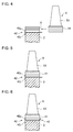
FIG 4 is a schematic view of a process of mounting a rotor blade to the rotor disc illustrated inFIG. 3 , after mounting a blade stopper to the rotor disc. -
FIG 5 is a schematic view of a state in which the rotor blade is mounted. -
FIG. 6 is a schematic view of a state in which the rotor blade is fixed by bending an end section of the blade stopper. -
FIG. 7 is a planar view of an example of a blade stopper according to the second embodiment. -
FIG. 8 is a partial enlarged view of a process of bending the bend portion of the blade stopper illustrated inFIG 7 . -
FIG 9 is a partial enlarged perspective view of a state in which the rotor blade is mounted to the rotor disc with the blade stopper illustrated inFIG. 7 . - Embodiments of the present invention will now be described in detail with reference to the accompanying drawings. It is intended, however, that unless particularly specified, dimensions, materials, shapes, relative positions and the like of components described in the embodiments shall be interpreted as illustrative only and not intended to limit the scope of the present invention.
-
FIG 1 illustrates aturbine rotor assembly 1 according to the first embodiment. Theturbine rotor assembly 1 is to be mounted to an axial-flow turbine, for instance, and includes arotor disc 2, a plurality of axial grooves 3 (seeFIG. 3 ) formed on the outer periphery of therotor disc 2, and agroup 5n of rotor blades arranged along the circumferential direction of therotor disc 2 and engaged with theaxial grooves 3 viablade stoppers 4. - In some embodiments, the
rotor disc 2 is a rotational disc which has a predetermined radius and which rotates about an axis of the axial-flow turbine. Theaxial grooves 3 formed on the outer periphery of therotor disc 2 surround the entire periphery at predetermined intervals and form a predetermined angle with respect to the axial direction. In an embodiment, theaxial grooves 3 are each a groove with stepped walls engraved in a V-shape to have a plurality of steps, the groove widening from a bottom section toward an outer peripheral section of therotor disc 2, as seen from the end surface of therotor disc 2 in the axial direction. Further, theaxial grooves 3 are formed to penetrate through therotor disc 2, and may be parallel to the axial direction of therotor disc 2 or may form a predetermined angle with respect to the axial direction of therotor disc 2. - The
group 5n of rotor blades includesindividual rotor blades 5 arranged at regular intervals in the respectiveaxial grooves 3 formed over the entire periphery of therotor disc 2. Each of therotor blades 5 substantially includes ablade root 51 formed to be capable of being fitted into corresponding one of theaxial grooves 3, aplatform 52, and ablade portion 53. In an embodiment, theblade root 51 is formed in a stepped and tapered shape so as to be fitted into theaxial groove 3. - The
blade stopper 4 is a thin plate member as illustrated inFIG. 2 , and has abase section 41 to be fitted into a groove portion at the side of the bottom section of theaxial groove 3, and a pair of end sections disposed on either end of thebase section 41 so as to protrude from theaxial groove 3 in the axial direction. The pair of end sections of theblade stopper 4 forms bendsections rotor disc 2, which is the radial direction, to contact the respective axial end surfaces of therotor disc 2. Thebend sections base section 41, in a direction intersecting with an axis of thebase section 41. - At least one of the
bend sections inward bend portion 42i) which protrudes from thebase section 41 outward and inward in the radial direction of therotor disc 2. The outward bend portion 42o protrudes from thebase section 41 outward in the radial direction of therotor disc 2, with theblade stopper 4 bended at a bending line at a boundary position between the at least onebend section 42 and thebase section 41. Theinward bend portion 42i protrudes from thebase section 41 inward in the radial direction of therotor disc 2, with theblade stopper 4 bended at a bending line at a boundary position between the at least onebend section 42 and thebase section 41. In the embodiment illustrated inFIG. 2 as an example, theblade stopper 4 has a pair ofinward bend portions 42i. - The
base section 41 has a length corresponding to the groove length of theaxial groove 3 formed on therotor disc 2. In other words, thebase section 41 has the substantially same dimension as that of theaxial groove 3 in the axial direction. Further, thebase section 41 and thebend sections axial groove 3 with respect to the axial direction. - Next, with regard to the
turbine rotor assembly 1 having the above configuration, a mounting process, i.e., a process of mounting therotor blades 5, will be described. - As illustrated in
FIG 3 , prior to mounting therotor blade 5 to therotor disc 2, theblade stopper 4 is attached to one of theaxial grooves 3 disposed next to one another on the outer periphery of therotor disc 2. - In the first step, the
blade stopper 4 is bended at bending lines between thebase section 41 and thebend sections 42 in preparation of mounting theblade stopper 4 to the correspondingaxial groove 3. At this time, from among thebend sections base section 41, thebend section 42 having the outward bend portion 42o and theinward bend portions 42i is bended outward in the radial direction. In this way, the outward bend portion 42o protrudes outward in the radial direction and theinward bend portions 42i protrude inward in the radial direction. - Next, in the second step, the
base section 41 of theblade stopper 4 is inserted into theaxial groove 3 from above to be fitted into theaxial groove 3. In an embodiment, thebase section 41 and theaxial groove 3 have substantially the same length dimensions, and theaxial groove 3 has stepped walls engraved in a V shape to have a plurality of steps. In this case, thebase section 41 can be fitted into theaxial groove 3 at a position where the width dimension of thebase section 41 is substantially the same as the groove width of theaxial groove 3. - Further, with the
base section 41 fitted into theaxial groove 3, the outward bend portion 42o and the pair ofinward bend portions 42i of thebend section 42 are in contact with the axial end surface of therotor disc 2, which makes it possible to support the axial end surface in a larger area than in a case where only the outward bend portion 42o is in contact. Thus, it is possible to support therotor blade 5 suitably against the force applied to therotor blade 5. At this stage, theother bend section 42 of theblade stopper 4 is not bended. - Next, in the third step, as illustrated in
FIG 4 , theblade root 51 of therotor blade 5 is inserted into theaxial groove 3 from the side of the non-bended one of the end sections of theblade stopper 4. In this way, it is possible to fit theblade root 51 into theaxial groove 3 formed in a stepped and tapered shape while avoiding interference between theblade stopper 4 and theblade root 51 of therotor blade 5. - Then, in the fourth step, the
bend section 42 of theblade stopper 4 not having been bended is finally bended outward in the radial direction. As a result, the joint between theblade root 51 of therotor blade 5 and theaxial groove 3 is held between both of thebend sections blade stopper 4 so as to be capable of sufficiently bearing at least the external force applied in the axial direction of the rotor disc 2 (seeFIG. 6 ). - It is possible to support the
rotor blade 5 particularly with respect to an external force applied to theblade portion 53 of therotor blade 5 when working fluid flows through thegroup 5n of turbine rotor blades from the upstream side toward the downstream side, because therotor blade 5 has the outward bend portion 42o and theinward bend portions 42i disposed at the downstream side so as to be in contact with the axial end surface of therotor disc 2 at the downstream side, which makes it is possible to resist the misalignment force applied to therotor blade 5 in a larger area than in a case where only the outward bend portion 42o is in contact with the end surface. - The present invention can be also implemented according to the second embodiment.
- In the second embodiment, as illustrated in
FIG. 7 , theblade stopper 4 has end sections protruding from theaxial groove 3 in the axial direction, and only one of thebend sections 42 includes the outward bend portion 42o protruding outward in the radial direction and theinward bend portions 42i protruding inward in the radial direction, as in the first embodiment. Further, the other bend section, which is thebend section 42 to be set on the upstream side in the axial direction of therotor disc 2, includes the second inward bend portions 42i2 being protrusions protruding in the longitudinal direction of the outward bend portion 42o. - The second inward bend portions 42i2 are bended inward in the radial direction (see
FIG. 8 ) after steps (first to fourth steps) similar to those in the first embodiment are completed. - Specifically, before being mounted to the
axial groove 3, theblade stopper 4 is bended at a bending line at the boundary between one of thebend sections 42 and the base section 41 (first step), and theblade stopper 4 in this state is inserted into theaxial groove 3 from above (second step), theblade root 51 of therotor blade 5 is inserted and fitted into theaxial groove 3 from the side of the non-bended end section of the blade stopper 4 (third step), and theother bend section 42 of theblade stopper 4 not having been bended is now bended outward in the radial direction (fourth step). Then, finally, the second bend portions 42i2 of theother bend section 42 are bended inward in the radial direction. - Accordingly, the second inward bend portions 42i2 form protrusions protruding inward in the radial direction and contact the axial end surface of the
rotor disc 2, so that the joint between theblade root 51 of therotor blade 5 and theaxial groove 3 is held between both of thebend sections blade stopper 4, which further improves the effect to prevent misalignment against at least the external force applied in the axial direction of the rotor disc 2 (seeFIG 9 ). - The first and second embodiments of the
turbine rotor assembly 1 of the present invention were described above with the structure and the mounting process. In at least one embodiment of the present invention, theblade stopper 4 is used so that thebend sections axial groove 3 in the axial direction further protrude inward in the radial direction, which makes it possible to sufficiently bear an external force applied to therotor disc 2 in the axial direction. - The present invention can be suitably applied not only to a turbine rotor assembly of an axial-flow turbine but also to any rotary machine to secure blades.
-
- 1
- Turbine rotor assembly
- 2
- Rotor disc
- 3
- Axial groove
- 4
- Blade stopper
- 41
- Base section
- 42
- Bend section
- 42o
- Outward bend portion
- 42i
- Inward bend portion
- 42i2
- Second inward bend portion
- 5
- Rotor blade
- 5n
- Group of rotor blades
- 51
- Blade root
- 52
- Platform
- 53
- Blade portion
Claims (5)
- A turbine rotor assembly, comprising:a rotor disc formed with a plurality of axial grooves on an outer periphery of the rotor disc; anda group of rotor blades arranged along a circumferential direction of the rotor disc and engaged with the axial grooves via blade stoppers,wherein each of the blade stoppers comprises:a base section fitted into corresponding one of the axial grooves; andbend sections disposed on opposite ends of the base section so as to protrude from the axial groove in an axial direction, the bend sections being bended in a radial direction of the rotor disc to be in contact with an axial end surface of the rotor disc, andwherein at least one of the bend sections at the opposite ends comprises an inward-and-outward bend part which protrudes on the axial end surface outward and inward in the radial direction of the rotor disc.
- The turbine rotor assembly according to claim 1,
wherein the inward-and-outward bend part is disposed on at least a downstream side with respect to a flow of working fluid which flows through the group of rotor blades. - The turbine rotor assembly according to claim 1 or 2,
wherein the inward-and-outward bend part comprises an outward bend portion and an inward bend portion which are bended outward and inward in the radial direction, respectively, the outward bend portion being formed into a substantially rectangular shape in a rotational-axis directional view, and the inward bend portion forming a protruding portion protruding inward from the outward bend portion. - A blade stopper for a turbine rotor assembly, the turbine rotor assembly comprising: a rotor disc formed with a plurality of axial grooves on an outer periphery of the rotor disc; and a group of rotor blades arranged along a circumferential direction of the rotor disc and engaged with the axial grooves via a plurality of blade stoppers, the group of rotor blades being fixed to the rotor disc via blade roots, and the blade stopper comprising:a base section configured to be fitted into corresponding one of the axial grooves, the base section having a length corresponding to a groove length of the axial groove; anda pair of end sections disposed on opposite ends of the base section and configured to be bended at a boundary position to the base section so as to be in contact with an axial end surface of the rotor disc, andwherein at least one of the pair of end sections comprises a protrusion protruding inward with respect to the base section from the boundary position between the at least one end section and the base section.
- A method of mounting the blade stopper to the turbine rotor assembly according to claim 1, the method comprising:a first step of forming the inward-and-outward bend part protruding inward and outward by bending one end of the blade stopper outward in the radial direction;a second step of fitting the base section of the blade stopper into the axial groove from above;a third step of inserting a blade root of the rotor blade into the axial groove from a side of the other end of the blade stopper; anda fourth step of bending the other end to fix the rotor blade in the axial groove via the blade stopper.
Applications Claiming Priority (2)
| Application Number | Priority Date | Filing Date | Title |
|---|---|---|---|
| JP2013239794A JP5999845B2 (en) | 2013-11-20 | 2013-11-20 | Turbine rotor assembly, blade stop plate in turbine rotor assembly, and method of assembling blade stop plate |
| PCT/JP2014/069897 WO2015075970A1 (en) | 2013-11-20 | 2014-07-29 | Turbine rotor assembly, blade stop plate for turbine rotor assembly, and method for assembling blade stop plate |
Publications (2)
| Publication Number | Publication Date |
|---|---|
| EP3023590A1 true EP3023590A1 (en) | 2016-05-25 |
| EP3023590A4 EP3023590A4 (en) | 2016-09-07 |
Family
ID=53179249
Family Applications (1)
| Application Number | Title | Priority Date | Filing Date |
|---|---|---|---|
| EP14864540.1A Withdrawn EP3023590A4 (en) | 2013-11-20 | 2014-07-29 | Turbine rotor assembly, blade stop plate for turbine rotor assembly, and method for assembling blade stop plate |
Country Status (5)
| Country | Link |
|---|---|
| EP (1) | EP3023590A4 (en) |
| JP (1) | JP5999845B2 (en) |
| KR (1) | KR20160030314A (en) |
| CN (1) | CN105473824A (en) |
| WO (1) | WO2015075970A1 (en) |
Cited By (3)
| Publication number | Priority date | Publication date | Assignee | Title |
|---|---|---|---|---|
| US10954791B2 (en) | 2016-01-13 | 2021-03-23 | Mitsubishi Power, Ltd. | Blade removal device and method |
| US11491591B2 (en) | 2019-03-29 | 2022-11-08 | Hirata Corporation | Attachment device |
| US11633817B2 (en) | 2019-03-29 | 2023-04-25 | Hirata Corporation | Manufacturing system |
Families Citing this family (7)
| Publication number | Priority date | Publication date | Assignee | Title |
|---|---|---|---|---|
| FR3057908B1 (en) * | 2016-10-21 | 2019-11-22 | Safran Aircraft Engines | ROTARY ASSEMBLY OF A TURBOMACHINE PROVIDED WITH AN AXIAL MAINTAINING SYSTEM OF A DAWN |
| SG11202110381PA (en) | 2019-03-29 | 2021-10-28 | Hirata Spinning | Measurement device |
| CN110259521B (en) * | 2019-07-31 | 2025-01-14 | 中国科学院工程热物理研究所 | A blade holder for impeller machinery |
| CN114076000B (en) * | 2020-08-17 | 2024-05-07 | 中国航发商用航空发动机有限责任公司 | Blade axial limiting device, blade disc structure and gas turbine |
| JP7416674B2 (en) * | 2020-08-25 | 2024-01-17 | 三菱重工業株式会社 | Turbine assembly method, turbine assembly support program, and turbine assembly support device |
| CN112096653B (en) * | 2020-11-18 | 2021-01-19 | 中国航发上海商用航空发动机制造有限责任公司 | Blade edge plate, blade ring, impeller disc and gas turbine engine |
| CN113478180B (en) * | 2021-07-15 | 2022-11-25 | 重庆江增船舶重工有限公司 | Machining method of locking sheet of supercharger and flanging tool thereof |
Family Cites Families (11)
| Publication number | Priority date | Publication date | Assignee | Title |
|---|---|---|---|---|
| US2801074A (en) * | 1952-10-01 | 1957-07-30 | United Aircraft Corp | Blade retaining means |
| US3045329A (en) * | 1959-07-30 | 1962-07-24 | Gen Electric | Method for assembling tongue-and-groove members with locking keys |
| JPH0414702U (en) * | 1990-05-24 | 1992-02-06 | ||
| JPH0514501U (en) | 1991-08-01 | 1993-02-26 | 三菱重工業株式会社 | Fluid machine rotor blades |
| JPH0618601U (en) * | 1992-08-10 | 1994-03-11 | 石川島播磨重工業株式会社 | Turbine blade damper |
| JPH10317907A (en) * | 1997-05-22 | 1998-12-02 | Hitachi Ltd | Compressor blade fixed structure |
| DE19757188A1 (en) * | 1997-12-22 | 1999-06-24 | Asea Brown Boveri | Single-stage axial turbine blade fixing device |
| US6190131B1 (en) * | 1999-08-31 | 2001-02-20 | General Electric Co. | Non-integral balanced coverplate and coverplate centering slot for a turbine |
| DE50209295D1 (en) | 2001-07-03 | 2007-03-08 | Abb Turbo Systems Ag | SECURING SYSTEM FOR RUNNING ROLLERS AXIAL THREE-POLE TURBOMA MACHINES |
| US8425194B2 (en) * | 2007-07-19 | 2013-04-23 | General Electric Company | Clamped plate seal |
| FR2921409B1 (en) * | 2007-09-25 | 2009-12-18 | Snecma | CLINKING FOR TURBOMACHINE DAWN. |
-
2013
- 2013-11-20 JP JP2013239794A patent/JP5999845B2/en active Active
-
2014
- 2014-07-29 WO PCT/JP2014/069897 patent/WO2015075970A1/en not_active Ceased
- 2014-07-29 EP EP14864540.1A patent/EP3023590A4/en not_active Withdrawn
- 2014-07-29 KR KR1020167003952A patent/KR20160030314A/en not_active Ceased
- 2014-07-29 CN CN201480046021.5A patent/CN105473824A/en active Pending
Cited By (3)
| Publication number | Priority date | Publication date | Assignee | Title |
|---|---|---|---|---|
| US10954791B2 (en) | 2016-01-13 | 2021-03-23 | Mitsubishi Power, Ltd. | Blade removal device and method |
| US11491591B2 (en) | 2019-03-29 | 2022-11-08 | Hirata Corporation | Attachment device |
| US11633817B2 (en) | 2019-03-29 | 2023-04-25 | Hirata Corporation | Manufacturing system |
Also Published As
| Publication number | Publication date |
|---|---|
| JP5999845B2 (en) | 2016-09-28 |
| JP2015098848A (en) | 2015-05-28 |
| KR20160030314A (en) | 2016-03-16 |
| EP3023590A4 (en) | 2016-09-07 |
| WO2015075970A1 (en) | 2015-05-28 |
| CN105473824A (en) | 2016-04-06 |
Similar Documents
| Publication | Publication Date | Title |
|---|---|---|
| JP5999845B2 (en) | Turbine rotor assembly, blade stop plate in turbine rotor assembly, and method of assembling blade stop plate | |
| CN107208490B (en) | The fixed device of blade with the locking device for turbo blade | |
| US8661641B2 (en) | Rotor blade assembly tool for gas turbine engine | |
| JP5611015B2 (en) | Turbine equipment | |
| RU2664726C1 (en) | Device for centring and guiding rotation of turbine engine shaft including improved means for retaining external bearing ring | |
| US9127559B2 (en) | Diaphragm for turbomachines and method of manufacture | |
| EP2687729A1 (en) | Rotor structure | |
| KR20110102908A (en) | Turbine wheel with system for supporting blades axially | |
| CN103375181A (en) | Turbine assembly | |
| US10787919B2 (en) | Mounting of vanes at the periphery of a turbine engine disc | |
| EP2803821A1 (en) | Blade device, blade system, and corresponding method of manufacturing a blade system | |
| CN105637182B (en) | Turbine blades and gas turbines | |
| EP2642077A1 (en) | Turbine rotor for a thermal electric power station | |
| JP5149831B2 (en) | Turbine blade fixed structure and turbine | |
| JP5449976B2 (en) | Shaft seal device, turbine device, and shaft seal device gap adjusting method | |
| JP7037929B2 (en) | Turbine blade and locking set | |
| JP2016205402A (en) | Blade stop plate | |
| US9151163B2 (en) | Turbomachine rotor disk | |
| US9695699B2 (en) | Securing blade assortment | |
| US9567861B2 (en) | Turbomachine vane cooperating with a vane retention disk | |
| EP2808490A1 (en) | Turbine blade with locking pin | |
| CN112576632B (en) | Installation Tools | |
| GB2566635A (en) | Assembly for attaching a nozzle to a structural element of a turbine engine | |
| JP2016070095A (en) | Turbine | |
| KR102365584B1 (en) | Guide blade arrangement of a turbomachine |
Legal Events
| Date | Code | Title | Description |
|---|---|---|---|
| PUAI | Public reference made under article 153(3) epc to a published international application that has entered the european phase |
Free format text: ORIGINAL CODE: 0009012 |
|
| 17P | Request for examination filed |
Effective date: 20160216 |
|
| AK | Designated contracting states |
Kind code of ref document: A1 Designated state(s): AL AT BE BG CH CY CZ DE DK EE ES FI FR GB GR HR HU IE IS IT LI LT LU LV MC MK MT NL NO PL PT RO RS SE SI SK SM TR |
|
| AX | Request for extension of the european patent |
Extension state: BA ME |
|
| A4 | Supplementary search report drawn up and despatched |
Effective date: 20160808 |
|
| RIC1 | Information provided on ipc code assigned before grant |
Ipc: F01D 5/30 20060101AFI20160802BHEP |
|
| DAX | Request for extension of the european patent (deleted) | ||
| STAA | Information on the status of an ep patent application or granted ep patent |
Free format text: STATUS: THE APPLICATION IS DEEMED TO BE WITHDRAWN |
|
| 18D | Application deemed to be withdrawn |
Effective date: 20170307 |