EP3023197A1 - Power tool counterweight arrangement and mass member - Google Patents
Power tool counterweight arrangement and mass member Download PDFInfo
- Publication number
- EP3023197A1 EP3023197A1 EP15193059.1A EP15193059A EP3023197A1 EP 3023197 A1 EP3023197 A1 EP 3023197A1 EP 15193059 A EP15193059 A EP 15193059A EP 3023197 A1 EP3023197 A1 EP 3023197A1
- Authority
- EP
- European Patent Office
- Prior art keywords
- platen
- counterweight
- drive shaft
- coupled
- power tool
- Prior art date
- Legal status (The legal status is an assumption and is not a legal conclusion. Google has not performed a legal analysis and makes no representation as to the accuracy of the status listed.)
- Granted
Links
Images



Classifications
-
- B—PERFORMING OPERATIONS; TRANSPORTING
- B24—GRINDING; POLISHING
- B24B—MACHINES, DEVICES, OR PROCESSES FOR GRINDING OR POLISHING; DRESSING OR CONDITIONING OF ABRADING SURFACES; FEEDING OF GRINDING, POLISHING, OR LAPPING AGENTS
- B24B23/00—Portable grinding machines, e.g. hand-guided; Accessories therefor
- B24B23/02—Portable grinding machines, e.g. hand-guided; Accessories therefor with rotating grinding tools; Accessories therefor
- B24B23/03—Portable grinding machines, e.g. hand-guided; Accessories therefor with rotating grinding tools; Accessories therefor the tool being driven in a combined movement
-
- B—PERFORMING OPERATIONS; TRANSPORTING
- B23—MACHINE TOOLS; METAL-WORKING NOT OTHERWISE PROVIDED FOR
- B23Q—DETAILS, COMPONENTS, OR ACCESSORIES FOR MACHINE TOOLS, e.g. ARRANGEMENTS FOR COPYING OR CONTROLLING; MACHINE TOOLS IN GENERAL CHARACTERISED BY THE CONSTRUCTION OF PARTICULAR DETAILS OR COMPONENTS; COMBINATIONS OR ASSOCIATIONS OF METAL-WORKING MACHINES, NOT DIRECTED TO A PARTICULAR RESULT
- B23Q11/00—Accessories fitted to machine tools for keeping tools or parts of the machine in good working condition or for cooling work; Safety devices specially combined with or arranged in, or specially adapted for use in connection with, machine tools
- B23Q11/0032—Arrangements for preventing or isolating vibrations in parts of the machine
- B23Q11/0035—Arrangements for preventing or isolating vibrations in parts of the machine by adding or adjusting a mass, e.g. counterweights
-
- B—PERFORMING OPERATIONS; TRANSPORTING
- B24—GRINDING; POLISHING
- B24B—MACHINES, DEVICES, OR PROCESSES FOR GRINDING OR POLISHING; DRESSING OR CONDITIONING OF ABRADING SURFACES; FEEDING OF GRINDING, POLISHING, OR LAPPING AGENTS
- B24B41/00—Component parts such as frames, beds, carriages, headstocks
- B24B41/007—Weight compensation; Temperature compensation; Vibration damping
Definitions
- This document relates, generally, to a power tool, and in particular, to a power tool for sanding a workpiece.
- a power tool may include a housing, a motor in the housing, a drive shaft, a first end portion of the drive shaft being coupled to the motor, a platen, a retainer bearing coupled to a first surface of the platen, an eccentric sleeve coupled to a second end portion of the drive shaft, the eccentric sleeve being coupled in the retainer bearing to eccentrically couple the drive shaft to the platen, and a counterweight coupled to the second end portion of the drive shaft, between the first surface of the platen and the eccentric sleeve.
- a power tool may include a motor, a drive shaft, a first end portion of the drive shaft being coupled to the motor, a platen, a retainer bearing coupled to a first surface of the platen, an eccentric sleeve coupled to a second end portion of the drive shaft, the eccentric sleeve being coupled in the retainer bearing to eccentrically couple the drive shaft to the platen, a counterweight coupled to the second end portion of the drive shaft, between the first surface of the platen and the eccentric sleeve, and a mass member included on the counterweight, positioned on a peripheral diametric edge portion of the counterweight.
- a power tool may include a motor, a drive shaft, a first end portion of the drive shaft being coupled to the motor, a platen, a retainer bearing coupled to the platen, a fan coupled to the drive shaft, the fan including a first counterweight and a hub portion, the drive shaft extending through an opening in the hub portion, a sleeve coupled to the hub portion of the fan, the sleeve being coupled in the retainer bearing, and a second counterweight coupled to a second end portion of the drive shaft, between the first surface of the platen and the sleeve.
- a power tool comprising a housing; a motor in the housing; a drive shaft, a first end portion of the drive shaft being coupled to the motor; a platen; a retainer bearing coupled to a first surface of the platen; an eccentric sleeve coupled to a second end portion of the drive shaft, the eccentric sleeve being coupled in the retainer bearing to eccentrically couple the drive shaft to the platen; an eccentric mass, including the eccentric sleeve, the retainer bearing and the platen coupled to the second end portion of the drive shaft; and a counterweight coupled to the second end portion of the drive shaft, between the first surface of the platen and the eccentric sleeve, wherein the counterweight is positioned such that a counterweight axis defined along a radial centerline of the counterweight is offset by a predetermined angle with respect to an orbit radius axis of the eccentric mass.
- a power tool comprising: a motor; a drive shaft, a first end portion of the drive shaft being coupled to the motor; a platen; a retainer bearing coupled to a first surface of the platen; an eccentric sleeve coupled to a second end portion of the drive shaft, the eccentric sleeve being coupled in the retainer bearing to eccentrically couple the drive shaft to the platen; a counterweight coupled to the second end portion of the drive shaft, between the first surface of the platen and the eccentric sleeve; and a mass member included on the counterweight, positioned on a peripheral diametric edge portion of the counterweight.
- the mass member can be positioned on one side of an orbit radius axis of an eccentric mass of the tool, the eccentric mass including the eccentric sleeve, the retainer bearing and the platen coupled to the second end portion of the drive shaft.
- the orbit radius axis can be defined by a line extending laterally through a longitudinally extending centerline of the drive shaft and a longitudinally extending centerline of the eccentric mass.
- the counterweight and mass member coupled thereto are configured to counteract forces generated due to interaction between the abrasive sheet and the finishing surface based on the position of the mass member on the counterweight, and the position of the counterweight adjacent to the first surface of the platen and proximate the second surface of the platen and the abrasive sheet coupled thereto.
- it can further comprise a housing, wherein the motor, the drive shaft, the retainer bearing, the eccentric sleeve and the counterweight are received in the housing, with the first surface of the platen facing an interior of the housing.
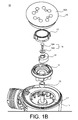
- FIGs. 1A-1B An example implementation of an eccentric motion power tool is shown in FIGs. 1A-1B .
- the exploded view of the example sanding tool 10 shown in FIG. 1B illustrates a housing 11 in which a motor is received, the motor rotating a drive shaft 12.
- a sanding platen 16, or sanding pad 16 may include a substantially planar outer surface 16A to which an abrasive finishing sheet, such as, for example, sandpaper may be affixed.
- a bearing retainer 14 may be positioned on an inner surface of the platen 16, at a location that is eccentric to the drive shaft 12, with an eccentric sleeve 15 coupling the drive shaft 12 to the retainer bearing 14, to convert the rotational force of the motor transmitted by the drive shaft 12 into an orbital movement of the platen 16.
- vibration of the tool 10 may increase due to additional external forces introduced by resistance between the finishing surface of the workpiece and the sandpaper.
- the counterweight may be arranged at a relatively small offset angle with respect to an orbit radius axis.
- the counterweight may be positioned as close to the source of this additional vibration and/or imbalance as possible, for example, as close to the lower surface of the platen as possible, for example, between the bearing retainer and the lower surface of the platen.
- the tool 200 may include a housing 210 in which a drive shaft 220 driven by a motor 230 is housed.
- the drive shaft 220 may be rotated by the motor 230 about a driven shaft centerline 220A.
- An eccentric sleeve 250 may be eccentrically positioned around a distal end portion of the drive shaft 220, centered about an eccentric mass centerline 250A that is offset from the driven shaft centerline 220A.
- the eccentric sleeve 250 may be retained by a bearing retainer 240 surrounding the eccentric sleeve 250, with the bearing retainer 240 coupled to an inner surface portion of a platen 260, or sanding pad 260.
- example implementations of sanding tools, units 1, 2 and 3 may achieve varying reductions in vibration level when the counterweight is positioned at a relatively small offset angle ⁇ .
- the graph shown in FIG. 2D illustrates vibration levels for three different units 1, 2 and 3, taken at three different orbit radii (1.2mm, 1.3mm and 1.4mm), ranging from an offset angle ⁇ of approximately 0.0 degrees to an offset angle ⁇ of approximately 12.0 degrees.
Landscapes
- Engineering & Computer Science (AREA)
- Mechanical Engineering (AREA)
- Finish Polishing, Edge Sharpening, And Grinding By Specific Grinding Devices (AREA)
Abstract

Description
- This application claims the benefit of
U.S. Provisional Application Serial No. 62/074,936, filed November 4, 2014 - This document relates, generally, to a power tool, and in particular, to a power tool for sanding a workpiece.
- Power tools, and in particular, power tools used to provide a desired surface finish on a workpiece, may include, for example, polishers, sheet sanders, random orbit sanders, and the like. Some of these types of power tools may employ an eccentric motion to remove material from the surface of the workpiece, and improve surface finish.
- In one aspect, a power tool may include a housing, a motor in the housing, a drive shaft, a first end portion of the drive shaft being coupled to the motor, a platen, a retainer bearing coupled to a first surface of the platen, an eccentric sleeve coupled to a second end portion of the drive shaft, the eccentric sleeve being coupled in the retainer bearing to eccentrically couple the drive shaft to the platen, and a counterweight coupled to the second end portion of the drive shaft, between the first surface of the platen and the eccentric sleeve. The counterweight may be positioned such that a counterweight axis defined along a radial centerline of the counterweight is offset by a predetermined angle with respect to an orbit radius axis of an eccentric mass including eccentric sleeve, retainer bearing and platen coupled to the second end portion of the drive shaft.
- In another aspect, a power tool may include a motor, a drive shaft, a first end portion of the drive shaft being coupled to the motor, a platen, a retainer bearing coupled to a first surface of the platen, an eccentric sleeve coupled to a second end portion of the drive shaft, the eccentric sleeve being coupled in the retainer bearing to eccentrically couple the drive shaft to the platen, a counterweight coupled to the second end portion of the drive shaft, between the first surface of the platen and the eccentric sleeve, and a mass member included on the counterweight, positioned on a peripheral diametric edge portion of the counterweight.
- In another aspect, a power tool may include a motor, a drive shaft, a first end portion of the drive shaft being coupled to the motor, a platen, a retainer bearing coupled to the platen, a fan coupled to the drive shaft, the fan including a first counterweight and a hub portion, the drive shaft extending through an opening in the hub portion, a sleeve coupled to the hub portion of the fan, the sleeve being coupled in the retainer bearing, and a second counterweight coupled to a second end portion of the drive shaft, between the first surface of the platen and the sleeve.
- According to a first aspect of the present invention, there is provided a power tool, comprising a housing; a motor in the housing; a drive shaft, a first end portion of the drive shaft being coupled to the motor; a platen; a retainer bearing coupled to a first surface of the platen; an eccentric sleeve coupled to a second end portion of the drive shaft, the eccentric sleeve being coupled in the retainer bearing to eccentrically couple the drive shaft to the platen; an eccentric mass, including the eccentric sleeve, the retainer bearing and the platen coupled to the second end portion of the drive shaft; and a counterweight coupled to the second end portion of the drive shaft, between the first surface of the platen and the eccentric sleeve, wherein the counterweight is positioned such that a counterweight axis defined along a radial centerline of the counterweight is offset by a predetermined angle with respect to an orbit radius axis of the eccentric mass.
- The orbit radius axis can be defined by a line extending laterally through a longitudinally extending centerline of the drive shaft and a longitudinally extending centerline of the eccentric mass.
- The predetermined angle can be greater than 0.0 degrees and less than or equal to 9.0 degrees. Ideally, the predetermined angle is greater than 0.0 degrees and less than or equal to 6.0 degrees. The predetermined angle can be determined based on an orbit radius defined by a lateral distance between a longitudinally extending centerline of the drive shaft and a longitudinally extending centerline of the eccentric mass. In such a design, a second surface of the platen, opposite the first surface of the platen can, face an exterior of the tool, the second surface of the platen being configured to receive an abrasive sheet engaging a finishing surface of a workpiece during operation of the power tool. Furthermore, the counterweight can be configured to counteract forces generated due to interaction between the abrasive sheet and the finishing surface based on the position of the counterweight, the position of the counterweight being offset by the predetermined angle with respect to the orbit radius axis, and the counterweight being positioned adjacent to the first surface of the platen and proximate the second surface of the platen and the abrasive sheet coupled thereto.
- According to a second aspect of the present invention there is provided a power tool, comprising: a motor; a drive shaft, a first end portion of the drive shaft being coupled to the motor; a platen; a retainer bearing coupled to a first surface of the platen; an eccentric sleeve coupled to a second end portion of the drive shaft, the eccentric sleeve being coupled in the retainer bearing to eccentrically couple the drive shaft to the platen; a counterweight coupled to the second end portion of the drive shaft, between the first surface of the platen and the eccentric sleeve; and a mass member included on the counterweight, positioned on a peripheral diametric edge portion of the counterweight.
- The mass member can be positioned on one side of an orbit radius axis of an eccentric mass of the tool, the eccentric mass including the eccentric sleeve, the retainer bearing and the platen coupled to the second end portion of the drive shaft. In such a design the orbit radius axis can be defined by a line extending laterally through a longitudinally extending centerline of the drive shaft and a longitudinally extending centerline of the eccentric mass.
- The mass member can be integrally formed with the counterweight as a single unit.
- A second surface of the platen, opposite the first surface of the platen, faces an exterior of the tool, the second surface of the platen being configured to receive an abrasive sheet engaging a finishing surface of a workpiece during operation of the power tool. Ideally, the counterweight and mass member coupled thereto are configured to counteract forces generated due to interaction between the abrasive sheet and the finishing surface based on the position of the mass member on the counterweight, and the position of the counterweight adjacent to the first surface of the platen and proximate the second surface of the platen and the abrasive sheet coupled thereto. Alternatively it can further comprise a housing, wherein the motor, the drive shaft, the retainer bearing, the eccentric sleeve and the counterweight are received in the housing, with the first surface of the platen facing an interior of the housing.
- According to a third aspect of the present invention, there is provided a power tool, comprising: a motor; a drive shaft, a first end portion of the drive shaft being coupled to the motor; a platen; a retainer bearing coupled to the platen; a fan coupled to the drive shaft, the fan including a first counterweight and a hub portion, the drive shaft extending through an opening in the hub portion; a sleeve coupled to the hub portion of the fan, the sleeve being coupled in the retainer bearing; and a second counterweight coupled to a second end portion of the drive shaft, between the first surface of the platen and the sleeve.
- The opening in the hub portion can be eccentrically positioned in the hub portion.
- Ideally, a mass of a first sector of the hub portion is greater than a mass of a second sector of the hub portion, such that the first sector defines the first counterweight. Furthermore, the first counterweight and the second counterweight can be configured to counteract forces generated due to interaction between an abrasive sheet coupled to a second surface of the platen and a finishing surface of a workpiece based on a position of the first counterweight and a position of the second counterweight adjacent to the first surface of the platen and proximate the second surface of the platen and the abrasive sheet coupled thereto.
- The details of one or more implementations are set forth in the accompanying drawings and the description below. Other features will be apparent from the description and drawings, and from the claims.
-
-
FIG. 1A is a perspective view of an example implementation of an eccentric motion power tool, andFIG. 1B is an exploded view of the tool shown inFIG. 1A . -
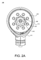
FIGs. 2A and2B are bottom views of a sanding tool, andFIG. 2C is a cross-sectional view of the sanding tool shown inFIGs. 2A and2B , in accordance with embodiments as broadly described herein. -
FIG. 2D is a graph of vibration levels of sanding tools having counterweights positioned at varying offset angles, and with varying orbit radii, in accordance with embodiments as broadly described herein. -
FIG. 3A is a bottom view of a sanding tool, andFIG. 3B is a cross-sectional view of the sanding tool shown inFIG. 3A , in accordance with embodiments as broadly described herein. -
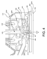
FIG. 4 is a cross-sectional view of a sanding tool, in accordance with embodiments as broadly described herein. - An example implementation of an eccentric motion power tool is shown in
FIGs. 1A-1B . The exploded view of theexample sanding tool 10 shown inFIG. 1B illustrates ahousing 11 in which a motor is received, the motor rotating adrive shaft 12. Asanding platen 16, orsanding pad 16, may include a substantially planarouter surface 16A to which an abrasive finishing sheet, such as, for example, sandpaper may be affixed. Abearing retainer 14 may be positioned on an inner surface of theplaten 16, at a location that is eccentric to thedrive shaft 12, with aneccentric sleeve 15 coupling thedrive shaft 12 to the retainer bearing 14, to convert the rotational force of the motor transmitted by thedrive shaft 12 into an orbital movement of theplaten 16. - To counteract imbalance in the
eccentric coupler 15 / retainer bearing 14 /platen 16 generated due to the eccentric coupling of theplaten 16 to thedrive shaft 12 during operation, in some embodiments, thetool 10 may include acounterweight 18 coupled to thedrive shaft 12. Acoupling device 19, such as, for example, awasher 19A and afastener 19B, may couple thecounterweight 18 in position at the end of thedrive shaft 12, with adust cap 17 covering the assembledcounterweight 18 and driveshaft 12. In some embodiments, thecounterweight 18 may be positioned opposite the center of gravity of theplaten 16, for example, approximately 180 degrees from the center of gravity of theplaten 16. Positioning of thecounterweight 18 in this manner may counteract imbalance and reduce vibration when the motor is rotating thedrive shaft 12. However, when theplaten 16, and in particular, a sheet of sandpaper attached to theouter surface 16A of theplaten 16, contacts a workpiece during operation, vibration of thetool 10 may increase due to additional external forces introduced by resistance between the finishing surface of the workpiece and the sandpaper. - To counteract an additional force, or force vector, generated due to the resistance between the finishing surface of the workpiece and the sandpaper, in some embodiments, the counterweight may be arranged at a relatively small offset angle with respect to an orbit radius axis. In some embodiments, the counterweight may be positioned as close to the source of this additional vibration and/or imbalance as possible, for example, as close to the lower surface of the platen as possible, for example, between the bearing retainer and the lower surface of the platen. Arranging the counterweight at a relatively small offset angle with respect to the orbit axis radius, and/or arranging the counterweight as close to the lower surface of the platen as possible may balance the rotating masses to reduce vibration and counteract the force vector generated due to the interaction between the sandpaper and the workpiece, thus reducing effective vibration of the tool engaged with a workpiece during operation.
-
FIGs. 2A and2B are bottom views of asanding tool 200, in accordance with an example implementation as broadly described herein, with a platen and a dust cap of thesanding tool 200 removed so that an arrangement of internal components is visible, andFIG. 2C is a cross-sectional view of thesanding tool 200 shown inFIGs. 2A and2B . - As shown in
FIGs. 2A and2B , thetool 200 may include ahousing 210 in which adrive shaft 220 driven by amotor 230 is housed. Thedrive shaft 220 may be rotated by themotor 230 about a drivenshaft centerline 220A. Aneccentric sleeve 250 may be eccentrically positioned around a distal end portion of thedrive shaft 220, centered about aneccentric mass centerline 250A that is offset from the drivenshaft centerline 220A. Theeccentric sleeve 250 may be retained by a bearingretainer 240 surrounding theeccentric sleeve 250, with the bearingretainer 240 coupled to an inner surface portion of aplaten 260, or sandingpad 260. Theplaten 260 may include anouter surface 260A to which anabrasive sheet 265, such as sandpaper, may be affixed. Acounterweight 280 may be coupled to the distal end of thedrive shaft 220, between the bearingretainer 240/eccentric sleeve 250 and theplaten 260. Acoupling device 290, including, for example, afastener 291 extending through awasher 292 positioned in a recess of thecounterweight 280 and into the distal end portion of thedrive shaft 220, may couple thecounterweight 280 in position relative to the bearingretainer 240,eccentric sleeve 250 and driveshaft 220, with adust cap 270 positioned between the end of the assembled components and theplaten 260. - As shown in
FIGs. 2B and2C , an orbit radius R may be defined by a distance between the drivenshaft centerline 220A and the eccentricmass centerline 250A, with an orbit radius axis RA defined by a line extending laterally through the longitudinally extending drivenshaft centerline 220A and the longitudinally extending eccentricmass centerline 250A. A counterweight axis CA may be defined by a line radially bisecting thecounterweight 280, with an angle θ formed between the orbit radius axis RA and the counterweight axis CA. The angle θ may define an offset angle of thecounterweight 280 with respect to the orbit radius axis RA. Offset of thecounterweight 280, for example by the offset angle θ, and proximity of thecounterweight 280 to theouter surface 260A of theplaten 260, may counteract imbalance, and may reduce vibration of thetool 200 engaged with a workpiece during operation. - In some embodiments, the offset angle θ may be greater than 0.0 and less than or equal to approximately 9.0 degrees to achieve a desired reduction in vibration levels. In some embodiments, the offset angle θ may be greater than 0.0 degrees and less than or equal to 6.0 degrees to achieve a desired reduction in vibration levels. In some embodiments, the offset angle θ may be between approximately 6.0 degrees and 9.0 degrees to achieve a desired reduction in vibration levels. In some embodiments, arrangement of the counterweight so that a portion of the counterweight mass is located as close to the plane of the workpiece as possible, and at an relatively small offset angle with respect to the orbit radius, as described above, may reduce vibration by up to approximately 40%, depending on, for example, orbit radius, operation speed and the like. For example, in one implementation, a tool vibration level, when the tool is actively engaged with a workpiece during operation, may be less than approximately 2.5 m/s2. Various combinations of orbit radius R, offset angle θ and resulting reductions in vibration levels are shown in Table 1 below.
Table 1 Combination Orbit Radius R (mm) Angle θ (Degrees) Vibration (m/s2) Unit 1Unit 2Unit 31 1.3 0 4.1 4.4 2 1.3 3 3.0 3.1 2.8 3 1.3 6 2.9 2.6 3.1 4 1.3 9 3.8 4.2 4.6 5 1.3 12 6.0 -- -- 6 1.4 0 3.8 -- -- 7 1.4 3 2.9 3.1 3.1 8 1.4 6 2.5 1.8 2.7 9 1.4 9 2.4 2.7 3.0 10 1.4 12 2.9 3.1 -- 11 1.4 15 -- 4.4 -- 12 1.2 3 3.1 3.4 3.4 13 1.2 6 3.1 3.0 3.1 14 1.2 9 4.7 5.3 4.2 - As shown in Table 1 above, and in the graph of
FIG. 2D , example implementations of sanding tools,units FIG. 2D illustrates vibration levels for threedifferent units - For example, in a first example implementation of a sanding tool represented by
combination 3 in Table 1, an example orbit radius of 1.3mm and an offset angle of approximately 6.0 degrees may result in a vibration level of approximately 2.6m/s2, resulting in an approximately 30% reduction in vibration compared to the same tool having an orbit radius of 1.3mm, but with the counterweight aligned with the driven shaft centerline (i.e., an offset angle of 0.0 degrees). In a second example implementation, represented by combination 8 in Table 1, an example orbit radius of 1.4mm and an offset angle of approximately 6.0 degrees may result in a vibration level of approximately 2.5m/s2, resulting in an approximately 34% reduction in vibration compared to the same tool having an orbit radius of 1.4mm, but with the counterweight aligned with the driven shaft centerline (i.e., an offset angle of 0.0 degrees). In a third example implementation, represented bycombination 9 in Table 1, an example orbit radius of 1.4mm and an offset angle of approximately 9.0 degrees may result in a vibration level of approximately 2.4m/s2, resulting in an approximately 37% reduction in vibration compared to the same tool having an orbit radius of 1.4mm, but with the counterweight aligned with the driven shaft centerline (i.e., an offset angle of 0.0 degrees). - As noted above, arrangement of the counterweight so that at least a portion of the counterweight mass is located as close to the plane of the workpiece as possible, and at an relatively small offset angle with respect to the orbit radius, rather than aligned with the driven shaft centerline, as described above, may reduce vibration to varying degrees, depending on various factors associated with a particular tool implementation, such as, for example, orbit radius, operation speed and the like.
-
FIG. 3A is a bottom view of asanding tool 300, in accordance with an example implementation as broadly described herein, with a platen and a dust cap of thesanding tool 300 removed so that an arrangement of internal components is visible, andFIG. 3B is a cross-sectional view of thesanding tool 300 shown inFIG. 3A . - The
tool 300 may include ahousing 310 housing adrive shaft 320 driven by amotor 330 to rotate about a drivenshaft centerline 320A, with aneccentric sleeve 350 eccentrically positioned around a distal end portion of thedrive shaft 320, centered about aneccentric mass centerline 350A, and retained by a bearingretainer 340 that is coupled to an inner surface portion of aplaten 360, similar to thetool 200 described above with respect toFIGs. 2A-2C . Theplaten 360 may include anouter surface 360A to which anabrasive sheet 365, such as sandpaper, may be affixed. Acounterweight 380 may be coupled to the distal end of thedrive shaft 320, between the bearingretainer 340/eccentric sleeve 350 and theplaten 360, by acoupling device 390, including, for example, afastener 391 and awasher 392, with adust cap 370 positioned between the end of the assembled components and theplaten 360. - The
counterweight 380 may include acounterforce mass member 385. Thecounterforce mass member 385 may be coupled to, or affixed to, or integral to thecounterweight 380, and may be positioned to a particular sector of thecounterweight 380, such as, for example, along adiameter line 381 of thecounterweight 380. Thecounterforce mass member 385 may be made of the same material as thecounterweight 380, or may be made of a different material than thecounterweight 380. In the example implementation shown inFIGs. 3A and3B , thecounterforce mass member 385 is substantially cylindrical. However, a shape or contour, relative size, and/or positioning of the counterforce mass member may be different that the example shown inFIGs. 3A and3B . - The
counterforce mass member 385 may be positioned on thecounterweight 380, on one side of the orbit radius axis RA opposite the remainder of thecounterweight 380, to increase the weight on the one side of thecounterweight 380. The additional mass added to the one side of thecounterweight 380 by thecounterforce mass member 385 may counteract imbalance and vibration generated by the rotating masses, that is, the rotation of the structure including theeccentric sleeve 350, bearingretainer 340 andplaten 360, thus reducing vibration of thetool 300 engaged with a workpiece during operation. - As discussed above, in the example implementation shown in
FIGs. 2A-2C , thecounterweight 280 is offset by the offset angle θ to counteract imbalance and vibration generated by the rotating masses (for example, rotation of the structure including theeccentric sleeve 250, bearingretainer 240 and platen 260). In the example implementation shown inFIGs. 3A and3B , thecounterforce mass member 385 provided on the counterweight may counteract the imbalance and vibration generated by the rotating masses, without this type of angular offset of thecounterweight 380. - The
counterweight 380 and thecounterforce mass member 385 may work together to counteract the imbalance and vibration generated by the rotating masses, and may reduce vibration of thetool 300 engaged with a workpiece during operation. In some embodiments, arrangement of thecounterweight 380 and thecounterforce mass member 385 so that a portion of the counterforce mass is located as close to the plane of the workpiece as possible, with thecounterweight 380 and thecounterforce mass member 385 positioned to counteract imbalance due to vibration generated by the rotating masses, may reduce vibration by up to approximately 40%, as discussed in detail above, so that when thetool 300 is actively engaged with a workpiece during operation, vibration may be less than approximately 2.5 m/s2. -
FIG. 4 is a cross-sectional view of a sanding tool 400, in accordance with an example implementation as broadly described herein. - The tool 400 may include a
housing 410 housing adrive shaft 420 driven by amotor 430 to rotate about a drivenshaft centerline 420A. Asleeve 450 may be retained by a bearingretainer 440 that is coupled to an inner surface portion of aplaten 460, similar to thetool 200 described above with respect toFIGs. 2A-2C and thetool 300 described above with respect toFIGs. 3A-3B . Theplaten 460 may include anouter surface 460A to which anabrasive sheet 465, such as sandpaper, may be affixed. - A
first counterweight 480, in the form of aweighted fan 480, may be positioned on thedrive shaft 420, adjacent to the bearingretainer 440, to generate a flow of air within thehousing 410 for cooling of the components received in thehousing 410 and/or to direct finishing material/sanding dust removed from the workpiece into a collection receptacle. A distal end portion of thedrive shaft 420 may be received in anopening 481 formed in ahub portion 482 of thefan 480. In some embodiments, theopening 481 may be eccentrically positioned in thehub 482, so that a first sector of thehub 482 includes more material than a second (opposite) sector of thehub 482, thus weighting thefan 480 in the area of the first (weighted) sector. In some embodiments, the distal end portion of thedrive shaft 420 may be tapered in a portion of thedrive shaft 420 corresponding to the weighted sector of thehub 482 of thefan 480. Thehub portion 482 of theweighted fan 480 may be coupled in thesleeve 450 and the bearingretainer 440, which is in turn coupled to theplaten 460. In some embodiments, asecond counterweight 486 may be coupled to the distal end of thedrive shaft 420, between the bearingretainer 440/sleeve 450 /hub portion 482 of theweighted fan 480 and theplaten 460. - The
first counterweight 480 and thesecond counterweight 486 may work together to counteract the imbalance and vibration generated by the rotating masses, and may reduce vibration of the tool 400 engaged with a workpiece during operation. In some embodiments, arrangement of thefirst counterweight 480 and thesecond counterweight 486 so that a portion of the counterweight mass is located as close to the plane of the workpiece as possible, with thefirst counterweight 480 and thesecond counterweight 486 positioned to counteract imbalance due to vibration generated by the rotating masses, may reduce vibration by up to approximately 40%, as discussed in detail above, so that when the tool 400 is actively engaged with a workpiece during operation, vibration may be less than approximately 2.5 m/s2. - While certain features of the described implementations have been illustrated as described herein, many modifications, substitutions, changes and equivalents will now occur to those skilled in the art. It is, therefore, to be understood that the appended claims are intended to cover all such modifications and changes as fall within the scope of the implementations. It should be understood that they have been presented by way of example only, not limitation, and various changes in form and details may be made. Any portion of the apparatus and/or methods described herein may be combined in any combination, except mutually exclusive combinations. The implementations described herein can include various combinations and/or sub-combinations of the functions, components and/or features of the different implementations described.
Claims (15)
- A power tool, comprising:a housing;a motor in the housing;a drive shaft, a first end portion of the drive shaft being coupled to the motor;a platen;a retainer bearing coupled to a first surface of the platen;an eccentric sleeve coupled to a second end portion of the drive shaft, the eccentric sleeve being coupled in the retainer bearing to eccentrically couple the drive shaft to the platen;an eccentric mass, including the eccentric sleeve, the retainer bearing and the platen coupled to the second end portion of the drive shaft; anda counterweight coupled to the second end portion of the drive shaft, between the first surface of the platen and the eccentric sleeve,wherein the counterweight is positioned such that a counterweight axis defined along a radial centerline of the counterweight is offset by a predetermined angle with respect to an orbit radius axis of the eccentric mass.
- The power tool of claim 1, wherein the orbit radius axis is defined by a line extending laterally through a longitudinally extending centerline of the drive shaft and a longitudinally extending centerline of the eccentric mass.
- The power tool of claim 1, wherein the predetermined angle is greater than 0.0 degrees and less than or equal to 9.0 degrees.
- The power tool of claim 3, wherein the predetermined angle is greater than 0.0 degrees and less than or equal to 6.0 degrees.
- The power tool of claim 1, wherein the predetermined angle is determined based on an orbit radius defined by a lateral distance between a longitudinally extending centerline of the drive shaft and a longitudinally extending centerline of the eccentric mass.
- The power tool of claim 5, wherein a second surface of the platen, opposite the first surface of the platen, faces an exterior of the tool, the second surface of the platen being configured to receive an abrasive sheet engaging a finishing surface of a workpiece during operation of the power tool.
- The power tool of claim 6, wherein the counterweight is configured to counteract forces generated due to interaction between the abrasive sheet and the finishing surface based on the position of the counterweight, the position of the counterweight being offset by the predetermined angle with respect to the orbit radius axis, and the counterweight being positioned adjacent to the first surface of the platen and proximate the second surface of the platen and the abrasive sheet coupled thereto.
- A power tool, comprising:a motor;a drive shaft, a first end portion of the drive shaft being coupled to the motor;a platen;a retainer bearing coupled to a first surface of the platen;an eccentric sleeve coupled to a second end portion of the drive shaft, the eccentric sleeve being coupled in the retainer bearing to eccentrically couple the drive shaft to the platen;a counterweight coupled to the second end portion of the drive shaft, between the first surface of the platen and the eccentric sleeve; anda mass member included on the counterweight, positioned on a peripheral diametric edge portion of the counterweight.
- The power tool of claim 8, wherein the mass member is positioned on one side of an orbit radius axis of an eccentric mass of the tool, the eccentric mass including the eccentric sleeve, the retainer bearing and the platen coupled to the second end portion of the drive shaft.
- The power tool of claim 9, wherein the orbit radius axis is defined by a line extending laterally through a longitudinally extending centerline of the drive shaft and a longitudinally extending centerline of the eccentric mass.
- The power tool of claim 8, wherein the mass member is integrally formed with the counterweight as a single unit.
- The power tool of claim 8, wherein a second surface of the platen, opposite the first surface of the platen, faces an exterior of the tool, the second surface of the platen being configured to receive an abrasive sheet engaging a finishing surface of a workpiece during operation of the power tool.
- The power tool of claim 12, wherein the counterweight and mass member coupled thereto are configured to counteract forces generated due to interaction between the abrasive sheet and the finishing surface based on the position of the mass member on the counterweight, and the position of the counterweight adjacent to the first surface of the platen and proximate the second surface of the platen and the abrasive sheet coupled thereto.
- The power tool of claim 12, further comprising a housing, wherein the motor, the drive shaft, the retainer bearing, the eccentric sleeve and the counterweight are received in the housing, with the first surface of the platen facing an interior of the housing.
- A power tool, comprising:a motor;a drive shaft, a first end portion of the drive shaft being coupled to the motor;a platen;a retainer bearing coupled to the platen;a fan coupled to the drive shaft, the fan including a first counterweight and a hub portion, the drive shaft extending through an opening in the hub portion;a sleeve coupled to the hub portion of the fan, the sleeve being coupled in the retainer bearing; anda second counterweight coupled to a second end portion of the drive shaft, between the first surface of the platen and the sleeve.
Applications Claiming Priority (2)
| Application Number | Priority Date | Filing Date | Title |
|---|---|---|---|
| US201462074936P | 2014-11-04 | 2014-11-04 | |
| US14/925,671 US20160121450A1 (en) | 2014-11-04 | 2015-10-28 | Power tool counterweight arrangement and mass member |
Publications (2)
| Publication Number | Publication Date |
|---|---|
| EP3023197A1 true EP3023197A1 (en) | 2016-05-25 |
| EP3023197B1 EP3023197B1 (en) | 2022-03-30 |
Family
ID=54366150
Family Applications (1)
| Application Number | Title | Priority Date | Filing Date |
|---|---|---|---|
| EP15193059.1A Active EP3023197B1 (en) | 2014-11-04 | 2015-11-04 | Power tool with counterweight arrangement |
Country Status (2)
| Country | Link |
|---|---|
| US (1) | US20160121450A1 (en) |
| EP (1) | EP3023197B1 (en) |
Families Citing this family (1)
| Publication number | Priority date | Publication date | Assignee | Title |
|---|---|---|---|---|
| CN114515987B (en) * | 2020-11-19 | 2026-03-13 | 南京泉峰科技有限公司 | Sanding machine |
Citations (7)
| Publication number | Priority date | Publication date | Assignee | Title |
|---|---|---|---|---|
| US2918761A (en) * | 1957-04-24 | 1959-12-29 | Sundstrand Corp | Rubbing machine |
| US3364625A (en) * | 1965-10-21 | 1968-01-23 | Albertson & Co Inc | Drive for surface-finishing tool |
| EP0203255A2 (en) * | 1985-05-25 | 1986-12-03 | Festo KG | Balanced orbital sander |
| US4854085A (en) * | 1987-09-24 | 1989-08-08 | Dynabrade, Inc. | Random orbital sander |
| WO2002024408A1 (en) * | 2000-09-23 | 2002-03-28 | Robert Bosch Gmbh | Motor-powered portable grinding machine |
| US20050197052A1 (en) * | 2004-03-03 | 2005-09-08 | Dynabrade, Inc. | Modular counterweight apparatus for an orbital abrading machine |
| EP1586416A2 (en) * | 2004-04-16 | 2005-10-19 | Positec Power Tools (Suzhou) Co., Ltd. | Anti-vibration arrangement |
Family Cites Families (3)
| Publication number | Priority date | Publication date | Assignee | Title |
|---|---|---|---|---|
| US2367668A (en) * | 1942-12-11 | 1945-01-23 | Roy J Champayne | Rubbing machine |
| US2751725A (en) * | 1954-08-13 | 1956-06-26 | Roy J Champayne | Orbital action rubbing machine |
| US5018314A (en) * | 1989-06-08 | 1991-05-28 | Makita Electric Works, Ltd. | Sander |
-
2015
- 2015-10-28 US US14/925,671 patent/US20160121450A1/en not_active Abandoned
- 2015-11-04 EP EP15193059.1A patent/EP3023197B1/en active Active
Patent Citations (7)
| Publication number | Priority date | Publication date | Assignee | Title |
|---|---|---|---|---|
| US2918761A (en) * | 1957-04-24 | 1959-12-29 | Sundstrand Corp | Rubbing machine |
| US3364625A (en) * | 1965-10-21 | 1968-01-23 | Albertson & Co Inc | Drive for surface-finishing tool |
| EP0203255A2 (en) * | 1985-05-25 | 1986-12-03 | Festo KG | Balanced orbital sander |
| US4854085A (en) * | 1987-09-24 | 1989-08-08 | Dynabrade, Inc. | Random orbital sander |
| WO2002024408A1 (en) * | 2000-09-23 | 2002-03-28 | Robert Bosch Gmbh | Motor-powered portable grinding machine |
| US20050197052A1 (en) * | 2004-03-03 | 2005-09-08 | Dynabrade, Inc. | Modular counterweight apparatus for an orbital abrading machine |
| EP1586416A2 (en) * | 2004-04-16 | 2005-10-19 | Positec Power Tools (Suzhou) Co., Ltd. | Anti-vibration arrangement |
Also Published As
| Publication number | Publication date |
|---|---|
| US20160121450A1 (en) | 2016-05-05 |
| EP3023197B1 (en) | 2022-03-30 |
Similar Documents
| Publication | Publication Date | Title |
|---|---|---|
| US10350721B2 (en) | Work tool | |
| EP1586416B1 (en) | Anti-vibration arrangement | |
| US7104873B1 (en) | Anti-vibration arrangement | |
| US20240025005A1 (en) | Hand-held and hand-guided random orbital polishing or sanding power tool | |
| US20200094432A1 (en) | Reciprocating tool | |
| CN211029448U (en) | sanding tool | |
| US8366518B2 (en) | Orbital smoothing device | |
| JPH11333692A (en) | Hand-held power tool | |
| US20170312877A1 (en) | Hand held or hand guided grinding or polishing machine tool | |
| CN103153535A (en) | Working tool, in particular electric tool | |
| CN107000156A (en) | Power tool system | |
| CN110944794A (en) | Grinding tool and its main body and grinding part | |
| US20220048158A1 (en) | Machine tool having a balancing device | |
| US20220126417A1 (en) | Machine tool having a balancing device | |
| EP4230346B1 (en) | Sanding machine | |
| JP7100527B2 (en) | Covers and tools | |
| CN117001486A (en) | Sander | |
| EP3023197B1 (en) | Power tool with counterweight arrangement | |
| CN1899765B (en) | Devices with at least two counterweights, eccentric tools and hand-held power tools | |
| EP2455197B1 (en) | Power tool | |
| CN105904293A (en) | Tool sharpener | |
| WO2019154292A1 (en) | Polishing tool | |
| CN117651625A (en) | Sander | |
| JP2013103326A (en) | Orbital sander | |
| US12539578B2 (en) | Plate-like backing pad adapted for releasable attachment to a hand-held polishing or sanding power tool |
Legal Events
| Date | Code | Title | Description |
|---|---|---|---|
| AK | Designated contracting states |
Kind code of ref document: A1 Designated state(s): AL AT BE BG CH CY CZ DE DK EE ES FI FR GB GR HR HU IE IS IT LI LT LU LV MC MK MT NL NO PL PT RO RS SE SI SK SM TR |
|
| AX | Request for extension of the european patent |
Extension state: BA ME |
|
| PUAI | Public reference made under article 153(3) epc to a published international application that has entered the european phase |
Free format text: ORIGINAL CODE: 0009012 |
|
| 17P | Request for examination filed |
Effective date: 20160718 |
|
| RBV | Designated contracting states (corrected) |
Designated state(s): AL AT BE BG CH CY CZ DE DK EE ES FI FR GB GR HR HU IE IS IT LI LT LU LV MC MK MT NL NO PL PT RO RS SE SI SK SM TR |
|
| STAA | Information on the status of an ep patent application or granted ep patent |
Free format text: STATUS: REQUEST FOR EXAMINATION WAS MADE |
|
| STAA | Information on the status of an ep patent application or granted ep patent |
Free format text: STATUS: EXAMINATION IS IN PROGRESS |
|
| 17Q | First examination report despatched |
Effective date: 20170907 |
|
| REG | Reference to a national code |
Ref country code: DE Ref legal event code: R079 Ref document number: 602015077821 Country of ref document: DE Free format text: PREVIOUS MAIN CLASS: B24B0001000000 Ipc: B24B0023030000 |
|
| RIC1 | Information provided on ipc code assigned before grant |
Ipc: B24B 41/00 20060101ALI20211029BHEP Ipc: B24B 23/03 20060101AFI20211029BHEP |
|
| GRAP | Despatch of communication of intention to grant a patent |
Free format text: ORIGINAL CODE: EPIDOSNIGR1 |
|
| STAA | Information on the status of an ep patent application or granted ep patent |
Free format text: STATUS: GRANT OF PATENT IS INTENDED |
|
| GRAS | Grant fee paid |
Free format text: ORIGINAL CODE: EPIDOSNIGR3 |
|
| INTG | Intention to grant announced |
Effective date: 20220124 |
|
| GRAA | (expected) grant |
Free format text: ORIGINAL CODE: 0009210 |
|
| STAA | Information on the status of an ep patent application or granted ep patent |
Free format text: STATUS: THE PATENT HAS BEEN GRANTED |
|
| AK | Designated contracting states |
Kind code of ref document: B1 Designated state(s): AL AT BE BG CH CY CZ DE DK EE ES FI FR GB GR HR HU IE IS IT LI LT LU LV MC MK MT NL NO PL PT RO RS SE SI SK SM TR |
|
| REG | Reference to a national code |
Ref country code: GB Ref legal event code: FG4D |
|
| REG | Reference to a national code |
Ref country code: CH Ref legal event code: EP |
|
| REG | Reference to a national code |
Ref country code: AT Ref legal event code: REF Ref document number: 1478733 Country of ref document: AT Kind code of ref document: T Effective date: 20220415 |
|
| REG | Reference to a national code |
Ref country code: DE Ref legal event code: R096 Ref document number: 602015077821 Country of ref document: DE |
|
| REG | Reference to a national code |
Ref country code: IE Ref legal event code: FG4D |
|
| REG | Reference to a national code |
Ref country code: LT Ref legal event code: MG9D |
|
| PG25 | Lapsed in a contracting state [announced via postgrant information from national office to epo] |
Ref country code: SE Free format text: LAPSE BECAUSE OF FAILURE TO SUBMIT A TRANSLATION OF THE DESCRIPTION OR TO PAY THE FEE WITHIN THE PRESCRIBED TIME-LIMIT Effective date: 20220330 Ref country code: RS Free format text: LAPSE BECAUSE OF FAILURE TO SUBMIT A TRANSLATION OF THE DESCRIPTION OR TO PAY THE FEE WITHIN THE PRESCRIBED TIME-LIMIT Effective date: 20220330 Ref country code: NO Free format text: LAPSE BECAUSE OF FAILURE TO SUBMIT A TRANSLATION OF THE DESCRIPTION OR TO PAY THE FEE WITHIN THE PRESCRIBED TIME-LIMIT Effective date: 20220630 Ref country code: LT Free format text: LAPSE BECAUSE OF FAILURE TO SUBMIT A TRANSLATION OF THE DESCRIPTION OR TO PAY THE FEE WITHIN THE PRESCRIBED TIME-LIMIT Effective date: 20220330 Ref country code: HR Free format text: LAPSE BECAUSE OF FAILURE TO SUBMIT A TRANSLATION OF THE DESCRIPTION OR TO PAY THE FEE WITHIN THE PRESCRIBED TIME-LIMIT Effective date: 20220330 Ref country code: BG Free format text: LAPSE BECAUSE OF FAILURE TO SUBMIT A TRANSLATION OF THE DESCRIPTION OR TO PAY THE FEE WITHIN THE PRESCRIBED TIME-LIMIT Effective date: 20220630 |
|
| REG | Reference to a national code |
Ref country code: NL Ref legal event code: MP Effective date: 20220330 |
|
| REG | Reference to a national code |
Ref country code: AT Ref legal event code: MK05 Ref document number: 1478733 Country of ref document: AT Kind code of ref document: T Effective date: 20220330 |
|
| PG25 | Lapsed in a contracting state [announced via postgrant information from national office to epo] |
Ref country code: LV Free format text: LAPSE BECAUSE OF FAILURE TO SUBMIT A TRANSLATION OF THE DESCRIPTION OR TO PAY THE FEE WITHIN THE PRESCRIBED TIME-LIMIT Effective date: 20220330 Ref country code: GR Free format text: LAPSE BECAUSE OF FAILURE TO SUBMIT A TRANSLATION OF THE DESCRIPTION OR TO PAY THE FEE WITHIN THE PRESCRIBED TIME-LIMIT Effective date: 20220701 Ref country code: FI Free format text: LAPSE BECAUSE OF FAILURE TO SUBMIT A TRANSLATION OF THE DESCRIPTION OR TO PAY THE FEE WITHIN THE PRESCRIBED TIME-LIMIT Effective date: 20220330 |
|
| PG25 | Lapsed in a contracting state [announced via postgrant information from national office to epo] |
Ref country code: NL Free format text: LAPSE BECAUSE OF FAILURE TO SUBMIT A TRANSLATION OF THE DESCRIPTION OR TO PAY THE FEE WITHIN THE PRESCRIBED TIME-LIMIT Effective date: 20220330 |
|
| PG25 | Lapsed in a contracting state [announced via postgrant information from national office to epo] |
Ref country code: SM Free format text: LAPSE BECAUSE OF FAILURE TO SUBMIT A TRANSLATION OF THE DESCRIPTION OR TO PAY THE FEE WITHIN THE PRESCRIBED TIME-LIMIT Effective date: 20220330 Ref country code: SK Free format text: LAPSE BECAUSE OF FAILURE TO SUBMIT A TRANSLATION OF THE DESCRIPTION OR TO PAY THE FEE WITHIN THE PRESCRIBED TIME-LIMIT Effective date: 20220330 Ref country code: RO Free format text: LAPSE BECAUSE OF FAILURE TO SUBMIT A TRANSLATION OF THE DESCRIPTION OR TO PAY THE FEE WITHIN THE PRESCRIBED TIME-LIMIT Effective date: 20220330 Ref country code: PT Free format text: LAPSE BECAUSE OF FAILURE TO SUBMIT A TRANSLATION OF THE DESCRIPTION OR TO PAY THE FEE WITHIN THE PRESCRIBED TIME-LIMIT Effective date: 20220801 Ref country code: ES Free format text: LAPSE BECAUSE OF FAILURE TO SUBMIT A TRANSLATION OF THE DESCRIPTION OR TO PAY THE FEE WITHIN THE PRESCRIBED TIME-LIMIT Effective date: 20220330 Ref country code: EE Free format text: LAPSE BECAUSE OF FAILURE TO SUBMIT A TRANSLATION OF THE DESCRIPTION OR TO PAY THE FEE WITHIN THE PRESCRIBED TIME-LIMIT Effective date: 20220330 Ref country code: CZ Free format text: LAPSE BECAUSE OF FAILURE TO SUBMIT A TRANSLATION OF THE DESCRIPTION OR TO PAY THE FEE WITHIN THE PRESCRIBED TIME-LIMIT Effective date: 20220330 Ref country code: AT Free format text: LAPSE BECAUSE OF FAILURE TO SUBMIT A TRANSLATION OF THE DESCRIPTION OR TO PAY THE FEE WITHIN THE PRESCRIBED TIME-LIMIT Effective date: 20220330 |
|
| PG25 | Lapsed in a contracting state [announced via postgrant information from national office to epo] |
Ref country code: PL Free format text: LAPSE BECAUSE OF FAILURE TO SUBMIT A TRANSLATION OF THE DESCRIPTION OR TO PAY THE FEE WITHIN THE PRESCRIBED TIME-LIMIT Effective date: 20220330 Ref country code: IS Free format text: LAPSE BECAUSE OF FAILURE TO SUBMIT A TRANSLATION OF THE DESCRIPTION OR TO PAY THE FEE WITHIN THE PRESCRIBED TIME-LIMIT Effective date: 20220730 Ref country code: AL Free format text: LAPSE BECAUSE OF FAILURE TO SUBMIT A TRANSLATION OF THE DESCRIPTION OR TO PAY THE FEE WITHIN THE PRESCRIBED TIME-LIMIT Effective date: 20220330 |
|
| REG | Reference to a national code |
Ref country code: DE Ref legal event code: R097 Ref document number: 602015077821 Country of ref document: DE |
|
| PG25 | Lapsed in a contracting state [announced via postgrant information from national office to epo] |
Ref country code: DK Free format text: LAPSE BECAUSE OF FAILURE TO SUBMIT A TRANSLATION OF THE DESCRIPTION OR TO PAY THE FEE WITHIN THE PRESCRIBED TIME-LIMIT Effective date: 20220330 |
|
| PLBE | No opposition filed within time limit |
Free format text: ORIGINAL CODE: 0009261 |
|
| STAA | Information on the status of an ep patent application or granted ep patent |
Free format text: STATUS: NO OPPOSITION FILED WITHIN TIME LIMIT |
|
| 26N | No opposition filed |
Effective date: 20230103 |
|
| PG25 | Lapsed in a contracting state [announced via postgrant information from national office to epo] |
Ref country code: SI Free format text: LAPSE BECAUSE OF FAILURE TO SUBMIT A TRANSLATION OF THE DESCRIPTION OR TO PAY THE FEE WITHIN THE PRESCRIBED TIME-LIMIT Effective date: 20220330 |
|
| PG25 | Lapsed in a contracting state [announced via postgrant information from national office to epo] |
Ref country code: MC Free format text: LAPSE BECAUSE OF FAILURE TO SUBMIT A TRANSLATION OF THE DESCRIPTION OR TO PAY THE FEE WITHIN THE PRESCRIBED TIME-LIMIT Effective date: 20220330 |
|
| REG | Reference to a national code |
Ref country code: CH Ref legal event code: PL |
|
| REG | Reference to a national code |
Ref country code: BE Ref legal event code: MM Effective date: 20221130 |
|
| PG25 | Lapsed in a contracting state [announced via postgrant information from national office to epo] |
Ref country code: LI Free format text: LAPSE BECAUSE OF NON-PAYMENT OF DUE FEES Effective date: 20221130 Ref country code: IT Free format text: LAPSE BECAUSE OF FAILURE TO SUBMIT A TRANSLATION OF THE DESCRIPTION OR TO PAY THE FEE WITHIN THE PRESCRIBED TIME-LIMIT Effective date: 20220330 Ref country code: CH Free format text: LAPSE BECAUSE OF NON-PAYMENT OF DUE FEES Effective date: 20221130 |
|
| PG25 | Lapsed in a contracting state [announced via postgrant information from national office to epo] |
Ref country code: LU Free format text: LAPSE BECAUSE OF NON-PAYMENT OF DUE FEES Effective date: 20221104 |
|
| P01 | Opt-out of the competence of the unified patent court (upc) registered |
Effective date: 20230912 |
|
| PG25 | Lapsed in a contracting state [announced via postgrant information from national office to epo] |
Ref country code: IE Free format text: LAPSE BECAUSE OF NON-PAYMENT OF DUE FEES Effective date: 20221104 |
|
| PG25 | Lapsed in a contracting state [announced via postgrant information from national office to epo] |
Ref country code: FR Free format text: LAPSE BECAUSE OF NON-PAYMENT OF DUE FEES Effective date: 20221130 Ref country code: BE Free format text: LAPSE BECAUSE OF NON-PAYMENT OF DUE FEES Effective date: 20221130 |
|
| PG25 | Lapsed in a contracting state [announced via postgrant information from national office to epo] |
Ref country code: HU Free format text: LAPSE BECAUSE OF FAILURE TO SUBMIT A TRANSLATION OF THE DESCRIPTION OR TO PAY THE FEE WITHIN THE PRESCRIBED TIME-LIMIT; INVALID AB INITIO Effective date: 20151104 |
|
| PG25 | Lapsed in a contracting state [announced via postgrant information from national office to epo] |
Ref country code: CY Free format text: LAPSE BECAUSE OF FAILURE TO SUBMIT A TRANSLATION OF THE DESCRIPTION OR TO PAY THE FEE WITHIN THE PRESCRIBED TIME-LIMIT Effective date: 20220330 |
|
| PG25 | Lapsed in a contracting state [announced via postgrant information from national office to epo] |
Ref country code: MK Free format text: LAPSE BECAUSE OF FAILURE TO SUBMIT A TRANSLATION OF THE DESCRIPTION OR TO PAY THE FEE WITHIN THE PRESCRIBED TIME-LIMIT Effective date: 20220330 |
|
| PG25 | Lapsed in a contracting state [announced via postgrant information from national office to epo] |
Ref country code: TR Free format text: LAPSE BECAUSE OF FAILURE TO SUBMIT A TRANSLATION OF THE DESCRIPTION OR TO PAY THE FEE WITHIN THE PRESCRIBED TIME-LIMIT Effective date: 20220330 |
|
| PG25 | Lapsed in a contracting state [announced via postgrant information from national office to epo] |
Ref country code: MT Free format text: LAPSE BECAUSE OF FAILURE TO SUBMIT A TRANSLATION OF THE DESCRIPTION OR TO PAY THE FEE WITHIN THE PRESCRIBED TIME-LIMIT Effective date: 20220330 |
|
| PGFP | Annual fee paid to national office [announced via postgrant information from national office to epo] |
Ref country code: DE Payment date: 20251118 Year of fee payment: 11 |
|
| PGFP | Annual fee paid to national office [announced via postgrant information from national office to epo] |
Ref country code: GB Payment date: 20251120 Year of fee payment: 11 |