EP3022532B1 - Magnetic flowmeter - Google Patents
Magnetic flowmeter Download PDFInfo
- Publication number
- EP3022532B1 EP3022532B1 EP13889522.2A EP13889522A EP3022532B1 EP 3022532 B1 EP3022532 B1 EP 3022532B1 EP 13889522 A EP13889522 A EP 13889522A EP 3022532 B1 EP3022532 B1 EP 3022532B1
- Authority
- EP
- European Patent Office
- Prior art keywords
- magnetic
- flow tube
- flow
- magnetic field
- process fluid
- Prior art date
- Legal status (The legal status is an assumption and is not a legal conclusion. Google has not performed a legal analysis and makes no representation as to the accuracy of the status listed.)
- Active
Links
Images



Classifications
-
- G—PHYSICS
- G01—MEASURING; TESTING
- G01F—MEASURING VOLUME, VOLUME FLOW, MASS FLOW OR LIQUID LEVEL; METERING BY VOLUME
- G01F1/00—Measuring the volume flow or mass flow of fluid or fluent solid material wherein the fluid passes through a meter in a continuous flow
- G01F1/56—Measuring the volume flow or mass flow of fluid or fluent solid material wherein the fluid passes through a meter in a continuous flow by using electric or magnetic effects
- G01F1/58—Measuring the volume flow or mass flow of fluid or fluent solid material wherein the fluid passes through a meter in a continuous flow by using electric or magnetic effects by electromagnetic flowmeters
- G01F1/588—Measuring the volume flow or mass flow of fluid or fluent solid material wherein the fluid passes through a meter in a continuous flow by using electric or magnetic effects by electromagnetic flowmeters combined constructions of electrodes, coils or magnetic circuits, accessories therefor
-
- G—PHYSICS
- G01—MEASURING; TESTING
- G01F—MEASURING VOLUME, VOLUME FLOW, MASS FLOW OR LIQUID LEVEL; METERING BY VOLUME
- G01F1/00—Measuring the volume flow or mass flow of fluid or fluent solid material wherein the fluid passes through a meter in a continuous flow
- G01F1/56—Measuring the volume flow or mass flow of fluid or fluent solid material wherein the fluid passes through a meter in a continuous flow by using electric or magnetic effects
- G01F1/58—Measuring the volume flow or mass flow of fluid or fluent solid material wherein the fluid passes through a meter in a continuous flow by using electric or magnetic effects by electromagnetic flowmeters
- G01F1/586—Measuring the volume flow or mass flow of fluid or fluent solid material wherein the fluid passes through a meter in a continuous flow by using electric or magnetic effects by electromagnetic flowmeters constructions of coils, magnetic circuits, accessories therefor
-
- G—PHYSICS
- G01—MEASURING; TESTING
- G01F—MEASURING VOLUME, VOLUME FLOW, MASS FLOW OR LIQUID LEVEL; METERING BY VOLUME
- G01F1/00—Measuring the volume flow or mass flow of fluid or fluent solid material wherein the fluid passes through a meter in a continuous flow
- G01F1/56—Measuring the volume flow or mass flow of fluid or fluent solid material wherein the fluid passes through a meter in a continuous flow by using electric or magnetic effects
- G01F1/58—Measuring the volume flow or mass flow of fluid or fluent solid material wherein the fluid passes through a meter in a continuous flow by using electric or magnetic effects by electromagnetic flowmeters
- G01F1/60—Circuits therefor
Definitions
- the present invention relates to flowmeters of the type that sense the flow of process fluid in industrial process plants. More specifically, the present invention relates to measurement of flow using a magnetic flowmeter.
- Magnetic flowmeters are known in the art and typically utilize an electrically insulated flow tube that carries a flow of process fluid past an electromagnetic coil and past a pair of electrodes.
- the electromagnetic coil applies an electromagnetic field to the flowing process fluid. Due to Faraday's Law of electromagnetic induction, a voltage or Electromotive Force (EMF) is generated between the pair of electrodes in the fluid. This voltage is a function of the strength of the applied magnetic field and is proportional to the fluid's rate of flow.
- EMF Electromotive Force
- the magnetic field can be generated by moving electrical charges.
- the magnetic field is often described using a mathematical description of the magnetic influence of electric currents and magnetic materials.
- the magnetic field at any given point is specified by a vector which has a direction and a magnitude (strength).
- the direction of the vector is determined by the direction in which the current is flowing through the coil.
- the strength and density of the magnetic field depends on the amount of the current and the area and shape of the coil. In particular, the total strength of the magnetic field increases with the length of the wire. For example, when a wire carrying a current is formed into a loop, the magnetic field concentrates inside the loop. When the wire is bent into multiple loops to form the coil, the magnetic field becomes even more concentrated.
- US 2014/0150567 ( DE102011079351 ) which describes a magneto inductive flow measuring device having a measuring tube and at least one magnet system arranged on the measuring tube.
- US 4,932,268 describes an electromagnetic flow measuring arrangement in which an electrically conductive fluid flows through a measuring tube in which a magnetic field is generated transversely of the flow direction.
- US 2004/149046 describes also a magnetic flowmeter.
- the present invention provides a flow tube assembly according to claim 1 and a method of measuring flow according to claim 9.
- a magnetic flowmeter for measuring flow rate of a process fluid includes: a magnetic coil arranged to apply a magnetic field to the process fluid.
- a pair of electrodes electrically couple to the process fluid and are arranged to sense a voltage induced in the process fluid related to the applied magnetic field and the flow rate of the process fluid.
- a flow tube of a non-conductive material is arranged to receive a flow of the process fluid therethrough. The flow tube carries the magnetic coil and the pair of electrodes.
- Flow meter circuitry applies a current to the magnetic coil and receives the voltage sensed by the pair of electrodes.
- a magnetic field spreader is positioned proximate the magnetic coil and is arranged to spread the magnetic field emanating from the magnetic coil and direct the magnetic field into the flow tube.
- An exterior wrapper extends around the assembly and completes a magnetic circuit by use of a magnetic metal piece, which is configured to secure the first magnetic coil between the first magnetic field spreader and the magnetic wrapper and magnetically couple the first magnetic coil to the magnetic wrapper.
- the present invention is directed to a magnetic flowmeter that measures a flow of process fluid through a flow tube.
- the magnetic flowmeter includes a magnetic field spreader positioned proximate a coil of the flowmeter.
- the magnetic field spreader can be arranged such that the magnetic field has a profile across the flow tube as desired.
- the spreader can be configured such that the magnetic field is more evenly distributed across the width of the flow tube.
- Other profiles can also be formed as desired.
- the invention includes the use of a magnetic wrapper around an outer circumference of the flow tube to provide a magnetic circuit.
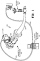
- FIG. 1 illustrates a typical environment 100 for magnetic flowmeter 102.
- Magnetic flowmeter 102 is shown coupled to process piping 104 that also couples to control valve 112.
- Magnetic flowmeter 102 is an example of one type of process variable transmitter which can be configured to monitor one or more process variables associated with fluids in a process plant such as slurries and liquids in chemicals, pulp, petroleum, gas, pharmaceutical, food and other fluid processing plants.
- Magnetic flowmeter 102 In a magnetic flowmeter, the monitored process variable relates to the velocity of process fluid through process piping and thus flow tube 108.
- Magnetic flowmeter 102 typically includes electronics housing 120 connected to flow tube 108. Magnetic flowmeter 102 outputs are configured for transmission over long distances to a controller or indicator via communication bus 106.
- communication bus 106 is a two-wire process control loop such as a 4-20 mA process control current loop, a FOUNDATIONTM Fieldbus connection, a pulse output/frequency output, a Highway Addressable Remote Transducer (HART®) protocol communication, or other connection to a controller such as system controller/monitor 110 or other suitable device.
- HART® Highway Addressable Remote Transducer
- System controller 110 is programmed as a process monitor, to display flow information for a human operator or as a process controller to control the process using control valve 112 over communication bus 106.
- FIG. 2 is a perspective cutaway view of a prior art magnetic flow tube assembly 109 which can be used with magnetic flowmeter 102.
- Flow tube assembler 109 includes electromagnetic coils 122 which are configured in a saddle shape and used to induce a magnetic field in fluid flowing through flow tube assembly 109.
- Electrodes 124 in flow tube assembly 109 are used to sense the EMF generated in the fluid due to the velocity of the flow and the applied magnetic field.
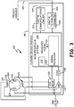
- FIG. 3 is a system block diagram of an embodiment showing various electrical components of a magnetic flowmeter for measuring a flow of a conductive process fluid through flow tube assembly 108.
- Coils 122 are configured to apply an external magnetic field in the fluid flow in response to an applied drive current from coil driver 130.
- Coil driver circuitry 130 provides the drive current to electromagnetic coils 122.
- EMF sensors (electrodes) 124 electrically couple to the fluid flow and provide an EMF signal output 134 to amplifier 132 related to an EMF generated in the fluid flow due to the applied magnetic field, and fluid velocity.
- Analog to digital converter 142 provides a digitized EMF signal to microprocessor system 148.
- a signal processor 150 is implemented in microprocessor system 148 of flow meter electronics 140 which couples to the EMF output 134 to provide an output 152 related to fluid velocity.
- Memory 178 can be used to store program instructions or other information as discussed below.
- a digital to analog converter 158 can be included and coupled to microprocessor system 148 to optionally generate an transmitter output 160, if desired, for coupling to communication bus 106.
- a digital communication circuit 162 optionally generates a digital transmitter output 164. The analog output 160 and the digital output 164 can be coupled to process controllers or monitors as desired.
- FIGS. 4A , 4B , 4C, and 4D show various views of a magnetic flow tube 108 in accordance with one example embodiment of the present invention.
- Magnetic flow tube 108 couples to the magnetic flowmeter 102 as illustrated in FIGS. 1 and 3 .
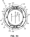
- FIG. 4A is a cross-sectional view
- FIG. 4B is a first perspective cross-sectional view
- FIG. 4C is a second perspective cross-sectional view
- FIG. 4D is an exploded view of flow tube assembly 108 in accordance with one example embodiment of the present invention.
- electromagnetic coils 124A,B generate a magnetic flux illustrated by arrows 200.
- the magnetic flow tube assembly 108 has at least an interior face which is formed of a non-conductive material.
- the process fluid flows through the interior flow tube 201 in a direction which is perpendicular to the cross-section illustrated in FIG. 4A .
- the magnetic flux 200 extends through an interior portion 202 of the magnetic flow tube assembly 108 whereby the flux 200 passes through process fluid flowing through the flow tube assembly 108.
- the magnetic flux lines 200 form a magnetic circuit in which the generated magnetic flux flows from coil 124B to coil 124A.
- the magnetic coil which receives the magnetic flux from the flow tube is identified as 124A and the magnetic coil from which the magnetic flux enters the flow tube assembly is identified as 124B. Note that the direction of the flux lines 200 may periodically reverse during operation.
- a magnetic circuit is formed by magnetic wrappers 206A and 206B positioned proximate an outer circumference of flow tube assembly 108 proximate electromagnetic coils 124A and 124B, respectively. Wrappers 206A, B form a tube exterior housing of flow tube assembly 108.
- Magnetic field spreaders 208A and 208B are positioned proximate an interior circumference of the magnetic flow tube assembly 108 proximate electromagnetic coils 124A and 124B, respectively.
- the arrows 200 which extend along wrappers 206A,B and spreaders 208A,B, along with arrows 200, shown in FIG. 4A illustrate the direction of the magnetic flux along the magnetic circuit within flow tube assembly 108.
- FIGS. 4B , 4C, and 4D show similar elements in different views. Additionally, in the exploded view of 4D, additional components are illustrated.
- flanges 220 are shown on opposed ends of flow tube assembly 108 which are used to couple the flow tube assembly 108 to process piping such as the process piping 104 shown in FIG. 1 .
- the electromagnetic coils 124A and B are formed by a coil spool 222A, 222B, coil wiring 224A, 224B, and coil cores 226A, 226B, respectively.
- a magnetic metal piece 230A and 230B secures coils 124A and 124B between wrappers 206A, 206B and magnetic spreaders 208A, 208B, respectively.
- Pieces 230A, B form a magnetic circuit and magnetically couple coils 124 A, B to wrappers 206A, B, respectively.
- the magnetic spreaders 208A, 208B cause the magnetic flux 200 which extends through the interior 202 of flow tube assembly 108 to be more evenly distributed across a cross-section of the interior portion 202.
- the magnetic spreaders 208A, 208B cause the magnetic flux to be spread radially beyond the edges of the electromagnetic coils 124A and 124B.
- the magnetic field 200 in the interior portion 202 can be configured whereby the exposure of the process fluid to the applied magnetic field 200 is more evenly distributed across a profile of the process fluid taken perpendicular to an axis of the flow tube assembly 108.
- the spreaders 208A,B spread the magnetic field 200 radially across the flow tube assembly 108.
- the profile of the magnetic field within the flow tube assembly 108 can be configured as desired. For example, by changing the shape and/or materials of the spreaders 208A,B, the magnetic field 200 can be configured to change in strength across the profile. In one example configuration, the profile strength may be increased in the center of the flow tube assembly 108 because there is a greater amount of process fluid flowing through this region. In another example, the spreaders 208A,B are configured to increase the strength of the magnetic field proximate the interior wall of the flow tube assembly 108.
- the various components of the flow tube assembly can be fabricated as desired.
- the wrappers 206A, 206B magnetic metal piece 230A, 230B as well as magnetic spreaders 208A, 208B can comprise a magnetic material for use in creating a magnetic circuit.
- These components may be fabricated as a single piece of magnetic material or may be formed by multiple piece such as by laminations.
- the magnetic wrappers 206A, 206B form a completely closed magnetic circuit around the outer circumference of the flow tube assembly 108. This reduces loss in the strength of the applied magnetic field 200.
- Magnetic spreaders 208A, 208B have a space formed therebetween which causes the magnetic field 200 to span this gap with a desired profile.
- other configurations may also be employed as desired.
- the present invention has been described with reference to preferred embodiments, workers skilled in the art will recognize that changes may be made in form and detail without departing from the scope of the invention as defined by the appended claims.
- various components have been illustrated with exemplary shapes and configurations, the present invention is not limited to the shapes and configurations.
- the wrappers, spreaders and coils may be changed as desired. Any appropriate material may be used for these components.
- the flow tube assembly may have other configurations.
- the flowmeter circuitry may operate as desired and is not limited to the particular electrical configuration shown herein.
- the flowmeter of the present invention may be used without requiring a process control loop.
- the applied magnetic field may be a state field or may vary with time.
- the applied magnetic field may alternate polarity and reverse directions.
- the term "flow tube” refers to the magnetic flow tube assembly. Although two magnetic wrappers are shown herein, any configuration of magnetic wrappers may be employed in order to provide a complete magnetic circuit. Similarly, any number of magnetic spreaders may be used as desired. In some configurations, any number of magnetic coils and/or electrodes may be employed. As used herein, “exterior” refers to a piece or component which is directly exposed to an external environment.
Landscapes
- Physics & Mathematics (AREA)
- Electromagnetism (AREA)
- Fluid Mechanics (AREA)
- General Physics & Mathematics (AREA)
- Engineering & Computer Science (AREA)
- Power Engineering (AREA)
- Measuring Volume Flow (AREA)
Description
- The present invention relates to flowmeters of the type that sense the flow of process fluid in industrial process plants. More specifically, the present invention relates to measurement of flow using a magnetic flowmeter.
- Magnetic flowmeters are known in the art and typically utilize an electrically insulated flow tube that carries a flow of process fluid past an electromagnetic coil and past a pair of electrodes. The electromagnetic coil applies an electromagnetic field to the flowing process fluid. Due to Faraday's Law of electromagnetic induction, a voltage or Electromotive Force (EMF) is generated between the pair of electrodes in the fluid. This voltage is a function of the strength of the applied magnetic field and is proportional to the fluid's rate of flow.
- The magnetic field can be generated by moving electrical charges. The magnetic field is often described using a mathematical description of the magnetic influence of electric currents and magnetic materials. The magnetic field at any given point is specified by a vector which has a direction and a magnitude (strength). The direction of the vector is determined by the direction in which the current is flowing through the coil. The strength and density of the magnetic field depends on the amount of the current and the area and shape of the coil. In particular, the total strength of the magnetic field increases with the length of the wire. For example, when a wire carrying a current is formed into a loop, the magnetic field concentrates inside the loop. When the wire is bent into multiple loops to form the coil, the magnetic field becomes even more concentrated.
- Further background may be found in
US 2014/0150567 (DE102011079351 ) which describes a magneto inductive flow measuring device having a measuring tube and at least one magnet system arranged on the measuring tube.US 4,932,268 describes an electromagnetic flow measuring arrangement in which an electrically conductive fluid flows through a measuring tube in which a magnetic field is generated transversely of the flow direction.US 2004/149046 describes also a magnetic flowmeter. - The present invention provides a flow tube assembly according to claim 1 and a method of measuring flow according to claim 9.
- A magnetic flowmeter for measuring flow rate of a process fluid includes: a magnetic coil arranged to apply a magnetic field to the process fluid. A pair of electrodes electrically couple to the process fluid and are arranged to sense a voltage induced in the process fluid related to the applied magnetic field and the flow rate of the process fluid. A flow tube of a non-conductive material is arranged to receive a flow of the process fluid therethrough. The flow tube carries the magnetic coil and the pair of electrodes. Flow meter circuitry applies a current to the magnetic coil and receives the voltage sensed by the pair of electrodes. A magnetic field spreader is positioned proximate the magnetic coil and is arranged to spread the magnetic field emanating from the magnetic coil and direct the magnetic field into the flow tube. An exterior wrapper extends around the assembly and completes a magnetic circuit by use of a magnetic metal piece, which is configured to secure the first magnetic coil between the first magnetic field spreader and the magnetic wrapper and magnetically couple the first magnetic coil to the magnetic wrapper.
-
-
FIG. 1 is a diagram showing a process control system including a magnetic flowmeter. -
FIG. 2 is a partial cutaway view of a prior art magnetic flow tube assembly. -
FIG. 3 is a simplified block diagram showing electrical components of a magnetic flowmeter. -
FIG. 4A is a front cross-sectional view of a magnetic flow tube assembly in accordance with one example embodiment of the present invention. -
FIG. 4B is a first cross-sectional perspective view of the magnetic flow tube assembly ofFIG. 4A . -
FIG. 4C is a second cross-sectional perspective view of the magnetic flow tube assembly ofFIG. 4A . -
FIG. 4D is a perspective exploded view of the magnetic flow tube assembly ofFIG. 4A . - The present invention is directed to a magnetic flowmeter that measures a flow of process fluid through a flow tube. The magnetic flowmeter includes a magnetic field spreader positioned proximate a coil of the flowmeter. The magnetic field spreader can be arranged such that the magnetic field has a profile across the flow tube as desired. For example, the spreader can be configured such that the magnetic field is more evenly distributed across the width of the flow tube. Other profiles can also be formed as desired. The invention includes the use of a magnetic wrapper around an outer circumference of the flow tube to provide a magnetic circuit.
-
FIG. 1 illustrates atypical environment 100 formagnetic flowmeter 102.Magnetic flowmeter 102 is shown coupled to processpiping 104 that also couples to controlvalve 112.Magnetic flowmeter 102 is an example of one type of process variable transmitter which can be configured to monitor one or more process variables associated with fluids in a process plant such as slurries and liquids in chemicals, pulp, petroleum, gas, pharmaceutical, food and other fluid processing plants. - In a magnetic flowmeter, the monitored process variable relates to the velocity of process fluid through process piping and thus
flow tube 108.Magnetic flowmeter 102 typically includeselectronics housing 120 connected toflow tube 108.Magnetic flowmeter 102 outputs are configured for transmission over long distances to a controller or indicator viacommunication bus 106. In typical processing plants,communication bus 106 is a two-wire process control loop such as a 4-20 mA process control current loop, a FOUNDATION™ Fieldbus connection, a pulse output/frequency output, a Highway Addressable Remote Transducer (HART®) protocol communication, or other connection to a controller such as system controller/monitor 110 or other suitable device. Additionally, wireless communication techniques may be implemented as desired including WIFI, or others such as WirelessHART® in accordance with the IEC 62591 Standard.System controller 110 is programmed as a process monitor, to display flow information for a human operator or as a process controller to control the process usingcontrol valve 112 overcommunication bus 106. -
FIG. 2 is a perspective cutaway view of a prior art magneticflow tube assembly 109 which can be used withmagnetic flowmeter 102.Flow tube assembler 109 includeselectromagnetic coils 122 which are configured in a saddle shape and used to induce a magnetic field in fluid flowing throughflow tube assembly 109.Electrodes 124 inflow tube assembly 109 are used to sense the EMF generated in the fluid due to the velocity of the flow and the applied magnetic field. -
FIG. 3 is a system block diagram of an embodiment showing various electrical components of a magnetic flowmeter for measuring a flow of a conductive process fluid throughflow tube assembly 108.Coils 122 are configured to apply an external magnetic field in the fluid flow in response to an applied drive current fromcoil driver 130.Coil driver circuitry 130 provides the drive current toelectromagnetic coils 122. EMF sensors (electrodes) 124 electrically couple to the fluid flow and provide an EMF signal output 134 to amplifier 132 related to an EMF generated in the fluid flow due to the applied magnetic field, and fluid velocity. Analog todigital converter 142 provides a digitized EMF signal tomicroprocessor system 148. Asignal processor 150 is implemented inmicroprocessor system 148 offlow meter electronics 140 which couples to the EMF output 134 to provide anoutput 152 related to fluid velocity.Memory 178 can be used to store program instructions or other information as discussed below. -
Microprocessor system 148 calculates velocity throughflow tube 108 in accordance with a relationship between the EMF output 134 and the flow velocity as set forth in Faraday's law, which states:
flow tube 108. B is the strength of the magnetic field in the fluid applied by the flow tube coils 122, and k is a constant of proportionality. A digital toanalog converter 158 can be included and coupled tomicroprocessor system 148 to optionally generate antransmitter output 160, if desired, for coupling tocommunication bus 106. Adigital communication circuit 162 optionally generates adigital transmitter output 164. Theanalog output 160 and thedigital output 164 can be coupled to process controllers or monitors as desired. -
FIGS. 4A ,4B ,4C, and 4D show various views of amagnetic flow tube 108 in accordance with one example embodiment of the present invention.Magnetic flow tube 108 couples to themagnetic flowmeter 102 as illustrated inFIGS. 1 and3 .FIG. 4A is a cross-sectional view,FIG. 4B is a first perspective cross-sectional view,FIG. 4C is a second perspective cross-sectional view andFIG. 4D is an exploded view offlow tube assembly 108 in accordance with one example embodiment of the present invention. - Referring to
FIG. 4A ,electromagnetic coils 124A,B generate a magnetic flux illustrated byarrows 200. The magneticflow tube assembly 108 has at least an interior face which is formed of a non-conductive material. The process fluid flows through theinterior flow tube 201 in a direction which is perpendicular to the cross-section illustrated inFIG. 4A . Themagnetic flux 200 extends through aninterior portion 202 of the magneticflow tube assembly 108 whereby theflux 200 passes through process fluid flowing through theflow tube assembly 108. Themagnetic flux lines 200 form a magnetic circuit in which the generated magnetic flux flows fromcoil 124B tocoil 124A. For reference inFIG. 4A , the magnetic coil which receives the magnetic flux from the flow tube is identified as 124A and the magnetic coil from which the magnetic flux enters the flow tube assembly is identified as 124B. Note that the direction of theflux lines 200 may periodically reverse during operation. A magnetic circuit is formed bymagnetic wrappers flow tube assembly 108 proximateelectromagnetic coils Wrappers 206A, B form a tube exterior housing offlow tube assembly 108. Some prior art configurations utilize a tube exterior housing which is separate from the magnetic wrapper.Magnetic field spreaders flow tube assembly 108 proximateelectromagnetic coils arrows 200 which extend alongwrappers 206A,B andspreaders 208A,B, along witharrows 200, shown inFIG. 4A illustrate the direction of the magnetic flux along the magnetic circuit withinflow tube assembly 108.FIGS. 4B ,4C, and 4D show similar elements in different views. Additionally, in the exploded view of 4D, additional components are illustrated. InFIG. 4D ,flanges 220 are shown on opposed ends offlow tube assembly 108 which are used to couple theflow tube assembly 108 to process piping such as the process piping 104 shown inFIG. 1 . Theelectromagnetic coils 124A and B are formed by acoil spool coil wiring coil cores magnetic metal piece coils wrappers magnetic spreaders Pieces 230A, B form a magnetic circuit and magnetically couple coils 124 A, B to wrappers 206A, B, respectively. - In accordance with one example embodiment of the present invention, the
magnetic spreaders magnetic flux 200 which extends through theinterior 202 offlow tube assembly 108 to be more evenly distributed across a cross-section of theinterior portion 202. As illustrated inFIG. 4A , themagnetic spreaders electromagnetic coils magnetic field 200 in theinterior portion 202 can be configured whereby the exposure of the process fluid to the appliedmagnetic field 200 is more evenly distributed across a profile of the process fluid taken perpendicular to an axis of theflow tube assembly 108. In the illustrated configuration, thespreaders 208A,B spread themagnetic field 200 radially across theflow tube assembly 108. The profile of the magnetic field within theflow tube assembly 108 can be configured as desired. For example, by changing the shape and/or materials of thespreaders 208A,B, themagnetic field 200 can be configured to change in strength across the profile. In one example configuration, the profile strength may be increased in the center of theflow tube assembly 108 because there is a greater amount of process fluid flowing through this region. In another example, thespreaders 208A,B are configured to increase the strength of the magnetic field proximate the interior wall of theflow tube assembly 108. - The various components of the flow tube assembly can be fabricated as desired. For example, the
wrappers magnetic metal piece magnetic spreaders - In the illustrated configuration, the
magnetic wrappers flow tube assembly 108. This reduces loss in the strength of the appliedmagnetic field 200.Magnetic spreaders magnetic field 200 to span this gap with a desired profile. However, other configurations may also be employed as desired. - Although the present invention has been described with reference to preferred embodiments, workers skilled in the art will recognize that changes may be made in form and detail without departing from the scope of the invention as defined by the appended claims. Although various components have been illustrated with exemplary shapes and configurations, the present invention is not limited to the shapes and configurations. The wrappers, spreaders and coils may be changed as desired. Any appropriate material may be used for these components. Similarly, the flow tube assembly may have other configurations. The flowmeter circuitry may operate as desired and is not limited to the particular electrical configuration shown herein. Similarly, in some configurations, the flowmeter of the present invention may be used without requiring a process control loop. The applied magnetic field may be a state field or may vary with time. In some configurations, the applied magnetic field may alternate polarity and reverse directions. As used herein, the term "flow tube" refers to the magnetic flow tube assembly. Although two magnetic wrappers are shown herein, any configuration of magnetic wrappers may be employed in order to provide a complete magnetic circuit. Similarly, any number of magnetic spreaders may be used as desired. In some configurations, any number of magnetic coils and/or electrodes may be employed. As used herein, "exterior" refers to a piece or component which is directly exposed to an external environment.
Claims (14)
- A flow tube assembly for use with a magnetic flowmeter for measuring flow rate of a process fluid, comprising:a flow tube (108) arranged to receive a flow of the process fluid therethrough;a first magnetic coil (122, 124A, 124B) arranged proximate the flow tube to apply a magnetic field (200) to the process fluid flowing through the flow tube;a pair of electrodes (124) electrically coupled to the process fluid in the flow tube and arranged to sense a voltage induced in the process fluid related to the applied magnetic field and a flow rate of the process fluid;a first magnetic field spreader (208A,B) positioned proximate an interior circumference of the magnetic flow tube assembly proximate the first magnetic coil arranged to spread the magnetic field from the first magnetic coil and direct the magnetic field into the flow tube in a plane perpendicular to the flow of process fluid; anda tube exterior housing which extends around the flow tube and forms a portion of a magnetic circuit with the first magnetic coil, wherein the tube exterior housing comprises a magnetic wrapper (206A,B) which extends around an outer circumference of the flow tube in the plane perpendicular to the flow of the process fluid and is magnetically coupled to the first magnetic coil,characterized in that a magnetic metal piece (230A,B) is configured to secure the first magnetic coil between the first magnetic field spreader (208A,B) and the tube exterior housing and magnetically couple the first magnetic coil to the tube exterior housing.
- A magnetic flowmeter (102) for measuring flow rate of a process fluid, comprising a flow tube assembly according to claim 1.
- The magnetic flowmeter of claim 2, wherein the first magnetic coil is arranged to apply the magnetic field in a plane perpendicular to the flow of process fluid through the flow tube.
- The magnetic flowmeter of claim 3, wherein the magnetic wrapper extends around the outer circumference of the flow tube in a plane perpendicular to the flow of process fluid through the flow tube.
- The magnetic flowmeter of claim 2 including a second magnetic coil (122, 124A, 124B) arranged proximate the flow tube to receive the applied magnetic field from the first magnetic coil, wherein the tube exterior housing extends between first and second coils, and optionally including a second magnetic field spreader (208A,B) positioned proximate the second magnetic coil.
- The magnetic flowmeter of claim 2 wherein the first magnetic field spreader directs the magnetic field into the flow tube with a profile substantially evenly distributed across a cross-section of the flow tube perpendicular to an axis of the flow tube or with an intensity that varies across a cross-section of the flow tube perpendicular to an axis of the flow tube.
- The magnetic flowmeter of claim 3 wherein the magnetic wrapper or the first magnetic field spreader is laminated.
- The magnetic flowmeter of claim 2 wherein the tube exterior housing comprises two semicircles.
- A method of measuring flow of process fluid using a magnetic flowmeter (102), comprising:receiving the flow of process fluid through a flow tube (108);applying a magnetic field (200) to the flow of process fluid through the flow tube using a first magnetic coil (122, 124A, 124B) carried by the flow tube;sensing a voltage generated in the process fluid which is related to the applied magnetic field and a flow rate of the process fluid through the flow tube;determining the flow rate of the process fluid based upon the sensed voltage;spreading the magnetic field which emanates from the first magnetic coil and directing a spread magnetic field into the flow tube in a plane perpendicular to the flow of process fluid using a first magnetic field spreader (208A,B) positioned proximate an interior circumference of the magnetic flow tube assembly proximate to the first magnetic coil; andcompleting a magnetic circuit with a tube exterior housing magnetically coupled to the magnetic coil, wherein the tube exterior housing comprises a magnetic wrapper (206A,B) which extends around an outer circumference of the flow tube in the plane perpendicular to flow of process fluid through the flow tube and is magnetically coupled to the first magnetic coil,wherein the first magnetic coil is secured between the first magnetic field spreader and the tube exterior housing and the first magnetic coil is magnetically coupled to the tube exterior housing through a magnetic metal piece (230A,B).
- The method of claim 9, wherein the first magnetic coil is arranged to apply the magnetic field in a plane perpendicular to the flow of process fluid through the flow tube, and wherein the magnetic wrapper extends around the outer circumference of the flow tube in a plane perpendicular to the flow of process fluid through the flow tube.
- The method of claim 9 including providing a second magnetic coil (122, 124A, 124B) arranged to receive the applied magnetic field from the first magnetic coil, and, optionally, providing a second magnetic field spreader (208A,B) positioned proximate the second magnetic coil.
- The method of claim 9 wherein the first magnetic field spreader directs the magnetic field into the flow tube with a profile substantially evenly distributed across a cross-section of the flow tube perpendicular to an axis of the flow tube, or with an intensity that varies across a cross-section of the flow tube perpendicular to an axis of the flow tube.
- The method of claim 9 wherein the magnetic wrapper or the first magnetic field spreader is laminated.
- The method of claim 9 including forming the tube exterior housing with two semicircles.
Applications Claiming Priority (1)
| Application Number | Priority Date | Filing Date | Title |
|---|---|---|---|
| PCT/CN2013/079689 WO2015006975A1 (en) | 2013-07-19 | 2013-07-19 | Magnetic flowmeter |
Publications (3)
| Publication Number | Publication Date |
|---|---|
| EP3022532A1 EP3022532A1 (en) | 2016-05-25 |
| EP3022532A4 EP3022532A4 (en) | 2017-04-05 |
| EP3022532B1 true EP3022532B1 (en) | 2021-10-13 |
Family
ID=52342490
Family Applications (1)
| Application Number | Title | Priority Date | Filing Date |
|---|---|---|---|
| EP13889522.2A Active EP3022532B1 (en) | 2013-07-19 | 2013-07-19 | Magnetic flowmeter |
Country Status (5)
| Country | Link |
|---|---|
| US (1) | US9429454B2 (en) |
| EP (1) | EP3022532B1 (en) |
| JP (1) | JP6161813B2 (en) |
| CN (1) | CN104662394B (en) |
| WO (1) | WO2015006975A1 (en) |
Cited By (1)
| Publication number | Priority date | Publication date | Assignee | Title |
|---|---|---|---|---|
| US12072219B2 (en) * | 2019-10-15 | 2024-08-27 | Enercorp Engineered Solutions, Llc | Apparatus for monitoring fluid flow in a pipe using electromagnetic velocity tomography |
Families Citing this family (6)
| Publication number | Priority date | Publication date | Assignee | Title |
|---|---|---|---|---|
| US11365995B2 (en) * | 2018-09-28 | 2022-06-21 | Georg Fischer Signet Llc | Magnetic flowmeter including auxiliary electrodes upstream and downstream of the pair of measuring electrodes and an adjustable brace |
| DE102018125865B4 (en) | 2018-10-18 | 2022-12-22 | Krohne Ag | Electromagnetic flowmeters, magnetic circuit devices and method of manufacturing a magnetic circuit device |
| US11156486B2 (en) | 2019-09-13 | 2021-10-26 | Micro Motion, Inc. | Magnetic flowmeter with improved processing |
| US11060893B2 (en) | 2019-09-13 | 2021-07-13 | Micro Motion Inc. | Magnetic flowmeter with flow independent autozero estimation |
| US11092470B2 (en) | 2019-09-13 | 2021-08-17 | Micro Motion Inc. | Magnetic flowmeter with noise adaptive dead time |
| CN116499537A (en) * | 2023-05-17 | 2023-07-28 | 承德菲时博特自动化设备有限公司 | A linerless electromagnetic flowmeter |
Citations (1)
| Publication number | Priority date | Publication date | Assignee | Title |
|---|---|---|---|---|
| US20040149046A1 (en) * | 2003-01-30 | 2004-08-05 | Yoshio Yamazaki | Measurement pipe for electromagnetic flowmeter |
Family Cites Families (18)
| Publication number | Priority date | Publication date | Assignee | Title |
|---|---|---|---|---|
| US3372589A (en) * | 1965-06-14 | 1968-03-12 | Fischer & Porter Co | Side-saddle magnetic flowmeter |
| US3690172A (en) | 1971-01-29 | 1972-09-12 | Fischer & Porter Co | Magnetic flowmeter having ferrous field armature |
| US4409846A (en) | 1979-02-08 | 1983-10-18 | Aichi Tokei Denki Co., Ltd. | Electromagnetic flow meter |
| JPS5866017A (en) * | 1981-10-16 | 1983-04-20 | Toshiba Corp | Electromagnetic flowmeter |
| EP0183859B1 (en) * | 1984-11-30 | 1990-07-11 | Flowtec Ag | Electromagnetic flow meter |
| DE3870125D1 (en) | 1987-10-01 | 1992-05-21 | Flowtec Ag | MAGNETIC-INDUCTIVE FLOW MEASUREMENT ARRANGEMENT. |
| GB2236394B (en) | 1989-09-26 | 1994-08-24 | Foxboro Co | Improvements in and relating to electromagnetic flowmeters |
| DK0649005T3 (en) | 1993-10-14 | 1997-10-13 | Flowtec Ag | Magnetic-inductive flow sensor |
| JPH07139980A (en) * | 1993-11-18 | 1995-06-02 | Fuji Electric Co Ltd | Electromagnetic flow meter |
| ES2105945B1 (en) | 1994-10-26 | 1998-05-01 | Hortsmann Largacha Peter | CONTROL CIRCUITS OF AN ELECTROMAGNETIC FLOWMETER. |
| JPH08261807A (en) * | 1995-03-24 | 1996-10-11 | Yamatake Honeywell Co Ltd | Electromagnetic flow meter |
| JPH09145436A (en) * | 1995-11-28 | 1997-06-06 | Yamatake Honeywell Co Ltd | Electromagnetic flow meter |
| US6611775B1 (en) * | 1998-12-10 | 2003-08-26 | Rosemount Inc. | Electrode leakage diagnostics in a magnetic flow meter |
| JP2009250732A (en) * | 2008-04-04 | 2009-10-29 | Keyence Corp | Measurement module |
| DE102008035740A1 (en) * | 2008-07-31 | 2010-02-04 | Abb Technology Ag | Magnetic inductive flow meter with a combined magnetic flux guide comprising Elektromagenteinheit |
| DE102011079351A1 (en) | 2011-07-18 | 2013-01-24 | Endress + Hauser Flowtec Ag | Magnetic-inductive flowmeter |
| US8991264B2 (en) * | 2012-09-26 | 2015-03-31 | Rosemount Inc. | Integrally molded magnetic flowmeter |
| US9027418B2 (en) * | 2012-09-28 | 2015-05-12 | Rosemount Inc. | Magnetic flowmeter |
-
2013
- 2013-07-19 JP JP2016526393A patent/JP6161813B2/en active Active
- 2013-07-19 US US14/113,637 patent/US9429454B2/en active Active
- 2013-07-19 CN CN201380000784.1A patent/CN104662394B/en active Active
- 2013-07-19 WO PCT/CN2013/079689 patent/WO2015006975A1/en not_active Ceased
- 2013-07-19 EP EP13889522.2A patent/EP3022532B1/en active Active
Patent Citations (1)
| Publication number | Priority date | Publication date | Assignee | Title |
|---|---|---|---|---|
| US20040149046A1 (en) * | 2003-01-30 | 2004-08-05 | Yoshio Yamazaki | Measurement pipe for electromagnetic flowmeter |
Cited By (1)
| Publication number | Priority date | Publication date | Assignee | Title |
|---|---|---|---|---|
| US12072219B2 (en) * | 2019-10-15 | 2024-08-27 | Enercorp Engineered Solutions, Llc | Apparatus for monitoring fluid flow in a pipe using electromagnetic velocity tomography |
Also Published As
| Publication number | Publication date |
|---|---|
| WO2015006975A1 (en) | 2015-01-22 |
| CN104662394A (en) | 2015-05-27 |
| CN104662394B (en) | 2018-06-01 |
| US20150020607A1 (en) | 2015-01-22 |
| US9429454B2 (en) | 2016-08-30 |
| EP3022532A1 (en) | 2016-05-25 |
| JP2016527496A (en) | 2016-09-08 |
| EP3022532A4 (en) | 2017-04-05 |
| JP6161813B2 (en) | 2017-07-12 |
Similar Documents
| Publication | Publication Date | Title |
|---|---|---|
| US9429454B2 (en) | Magnetic flowmeter | |
| EP2901107B1 (en) | Integrally molded magnetic flowmeter | |
| CA2886198C (en) | Magnetic flowmeter with multiple coils | |
| CA2886515C (en) | Magnetic flowmeter | |
| EP3120116B1 (en) | Magnetic core configuration for magnetic flowmeters | |
| EP4271968B1 (en) | An electromagnetic flowmeter with a plurality of coils | |
| EP3019835B1 (en) | Improved magnetic core configuration for magnetic flowmeters | |
| WO2018193294A1 (en) | An electromagnetic flowmeter | |
| WO2018100447A1 (en) | An attachable electromagnetic flowmeter | |
| AU2012391043B9 (en) | Magnetic flowmeter | |
| WO2018229523A1 (en) | An electromagnetic flowmeter assembly |
Legal Events
| Date | Code | Title | Description |
|---|---|---|---|
| PUAI | Public reference made under article 153(3) epc to a published international application that has entered the european phase |
Free format text: ORIGINAL CODE: 0009012 |
|
| 17P | Request for examination filed |
Effective date: 20160129 |
|
| AK | Designated contracting states |
Kind code of ref document: A1 Designated state(s): AL AT BE BG CH CY CZ DE DK EE ES FI FR GB GR HR HU IE IS IT LI LT LU LV MC MK MT NL NO PL PT RO RS SE SI SK SM TR |
|
| AX | Request for extension of the european patent |
Extension state: BA ME |
|
| DAX | Request for extension of the european patent (deleted) | ||
| A4 | Supplementary search report drawn up and despatched |
Effective date: 20170303 |
|
| RIC1 | Information provided on ipc code assigned before grant |
Ipc: G01F 1/60 20060101ALI20170227BHEP Ipc: G01F 1/58 20060101AFI20170227BHEP |
|
| STAA | Information on the status of an ep patent application or granted ep patent |
Free format text: STATUS: REQUEST FOR EXAMINATION WAS MADE |
|
| STAA | Information on the status of an ep patent application or granted ep patent |
Free format text: STATUS: EXAMINATION IS IN PROGRESS |
|
| 17Q | First examination report despatched |
Effective date: 20200708 |
|
| GRAP | Despatch of communication of intention to grant a patent |
Free format text: ORIGINAL CODE: EPIDOSNIGR1 |
|
| STAA | Information on the status of an ep patent application or granted ep patent |
Free format text: STATUS: GRANT OF PATENT IS INTENDED |
|
| INTG | Intention to grant announced |
Effective date: 20210203 |
|
| GRAS | Grant fee paid |
Free format text: ORIGINAL CODE: EPIDOSNIGR3 |
|
| GRAA | (expected) grant |
Free format text: ORIGINAL CODE: 0009210 |
|
| STAA | Information on the status of an ep patent application or granted ep patent |
Free format text: STATUS: THE PATENT HAS BEEN GRANTED |
|
| RAP1 | Party data changed (applicant data changed or rights of an application transferred) |
Owner name: ROSEMOUNT INC. |
|
| AK | Designated contracting states |
Kind code of ref document: B1 Designated state(s): AL AT BE BG CH CY CZ DE DK EE ES FI FR GB GR HR HU IE IS IT LI LT LU LV MC MK MT NL NO PL PT RO RS SE SI SK SM TR |
|
| RAP1 | Party data changed (applicant data changed or rights of an application transferred) |
Owner name: MICRO MOTION, INC. |
|
| REG | Reference to a national code |
Ref country code: GB Ref legal event code: FG4D |
|
| REG | Reference to a national code |
Ref country code: CH Ref legal event code: EP |
|
| REG | Reference to a national code |
Ref country code: DE Ref legal event code: R096 Ref document number: 602013079666 Country of ref document: DE |
|
| REG | Reference to a national code |
Ref country code: IE Ref legal event code: FG4D |
|
| REG | Reference to a national code |
Ref country code: AT Ref legal event code: REF Ref document number: 1438495 Country of ref document: AT Kind code of ref document: T Effective date: 20211115 |
|
| REG | Reference to a national code |
Ref country code: LT Ref legal event code: MG9D |
|
| REG | Reference to a national code |
Ref country code: NL Ref legal event code: MP Effective date: 20211013 |
|
| REG | Reference to a national code |
Ref country code: AT Ref legal event code: MK05 Ref document number: 1438495 Country of ref document: AT Kind code of ref document: T Effective date: 20211013 |
|
| PG25 | Lapsed in a contracting state [announced via postgrant information from national office to epo] |
Ref country code: RS Free format text: LAPSE BECAUSE OF FAILURE TO SUBMIT A TRANSLATION OF THE DESCRIPTION OR TO PAY THE FEE WITHIN THE PRESCRIBED TIME-LIMIT Effective date: 20211013 Ref country code: LT Free format text: LAPSE BECAUSE OF FAILURE TO SUBMIT A TRANSLATION OF THE DESCRIPTION OR TO PAY THE FEE WITHIN THE PRESCRIBED TIME-LIMIT Effective date: 20211013 Ref country code: FI Free format text: LAPSE BECAUSE OF FAILURE TO SUBMIT A TRANSLATION OF THE DESCRIPTION OR TO PAY THE FEE WITHIN THE PRESCRIBED TIME-LIMIT Effective date: 20211013 Ref country code: BG Free format text: LAPSE BECAUSE OF FAILURE TO SUBMIT A TRANSLATION OF THE DESCRIPTION OR TO PAY THE FEE WITHIN THE PRESCRIBED TIME-LIMIT Effective date: 20220113 Ref country code: AT Free format text: LAPSE BECAUSE OF FAILURE TO SUBMIT A TRANSLATION OF THE DESCRIPTION OR TO PAY THE FEE WITHIN THE PRESCRIBED TIME-LIMIT Effective date: 20211013 |
|
| PG25 | Lapsed in a contracting state [announced via postgrant information from national office to epo] |
Ref country code: IS Free format text: LAPSE BECAUSE OF FAILURE TO SUBMIT A TRANSLATION OF THE DESCRIPTION OR TO PAY THE FEE WITHIN THE PRESCRIBED TIME-LIMIT Effective date: 20220213 Ref country code: SE Free format text: LAPSE BECAUSE OF FAILURE TO SUBMIT A TRANSLATION OF THE DESCRIPTION OR TO PAY THE FEE WITHIN THE PRESCRIBED TIME-LIMIT Effective date: 20211013 Ref country code: PT Free format text: LAPSE BECAUSE OF FAILURE TO SUBMIT A TRANSLATION OF THE DESCRIPTION OR TO PAY THE FEE WITHIN THE PRESCRIBED TIME-LIMIT Effective date: 20220214 Ref country code: PL Free format text: LAPSE BECAUSE OF FAILURE TO SUBMIT A TRANSLATION OF THE DESCRIPTION OR TO PAY THE FEE WITHIN THE PRESCRIBED TIME-LIMIT Effective date: 20211013 Ref country code: NO Free format text: LAPSE BECAUSE OF FAILURE TO SUBMIT A TRANSLATION OF THE DESCRIPTION OR TO PAY THE FEE WITHIN THE PRESCRIBED TIME-LIMIT Effective date: 20220113 Ref country code: NL Free format text: LAPSE BECAUSE OF FAILURE TO SUBMIT A TRANSLATION OF THE DESCRIPTION OR TO PAY THE FEE WITHIN THE PRESCRIBED TIME-LIMIT Effective date: 20211013 Ref country code: LV Free format text: LAPSE BECAUSE OF FAILURE TO SUBMIT A TRANSLATION OF THE DESCRIPTION OR TO PAY THE FEE WITHIN THE PRESCRIBED TIME-LIMIT Effective date: 20211013 Ref country code: HR Free format text: LAPSE BECAUSE OF FAILURE TO SUBMIT A TRANSLATION OF THE DESCRIPTION OR TO PAY THE FEE WITHIN THE PRESCRIBED TIME-LIMIT Effective date: 20211013 Ref country code: GR Free format text: LAPSE BECAUSE OF FAILURE TO SUBMIT A TRANSLATION OF THE DESCRIPTION OR TO PAY THE FEE WITHIN THE PRESCRIBED TIME-LIMIT Effective date: 20220114 Ref country code: ES Free format text: LAPSE BECAUSE OF FAILURE TO SUBMIT A TRANSLATION OF THE DESCRIPTION OR TO PAY THE FEE WITHIN THE PRESCRIBED TIME-LIMIT Effective date: 20211013 |
|
| REG | Reference to a national code |
Ref country code: DE Ref legal event code: R097 Ref document number: 602013079666 Country of ref document: DE |
|
| PG25 | Lapsed in a contracting state [announced via postgrant information from national office to epo] |
Ref country code: SM Free format text: LAPSE BECAUSE OF FAILURE TO SUBMIT A TRANSLATION OF THE DESCRIPTION OR TO PAY THE FEE WITHIN THE PRESCRIBED TIME-LIMIT Effective date: 20211013 Ref country code: SK Free format text: LAPSE BECAUSE OF FAILURE TO SUBMIT A TRANSLATION OF THE DESCRIPTION OR TO PAY THE FEE WITHIN THE PRESCRIBED TIME-LIMIT Effective date: 20211013 Ref country code: RO Free format text: LAPSE BECAUSE OF FAILURE TO SUBMIT A TRANSLATION OF THE DESCRIPTION OR TO PAY THE FEE WITHIN THE PRESCRIBED TIME-LIMIT Effective date: 20211013 Ref country code: EE Free format text: LAPSE BECAUSE OF FAILURE TO SUBMIT A TRANSLATION OF THE DESCRIPTION OR TO PAY THE FEE WITHIN THE PRESCRIBED TIME-LIMIT Effective date: 20211013 Ref country code: DK Free format text: LAPSE BECAUSE OF FAILURE TO SUBMIT A TRANSLATION OF THE DESCRIPTION OR TO PAY THE FEE WITHIN THE PRESCRIBED TIME-LIMIT Effective date: 20211013 Ref country code: CZ Free format text: LAPSE BECAUSE OF FAILURE TO SUBMIT A TRANSLATION OF THE DESCRIPTION OR TO PAY THE FEE WITHIN THE PRESCRIBED TIME-LIMIT Effective date: 20211013 |
|
| PLBE | No opposition filed within time limit |
Free format text: ORIGINAL CODE: 0009261 |
|
| STAA | Information on the status of an ep patent application or granted ep patent |
Free format text: STATUS: NO OPPOSITION FILED WITHIN TIME LIMIT |
|
| 26N | No opposition filed |
Effective date: 20220714 |
|
| PG25 | Lapsed in a contracting state [announced via postgrant information from national office to epo] |
Ref country code: AL Free format text: LAPSE BECAUSE OF FAILURE TO SUBMIT A TRANSLATION OF THE DESCRIPTION OR TO PAY THE FEE WITHIN THE PRESCRIBED TIME-LIMIT Effective date: 20211013 |
|
| PG25 | Lapsed in a contracting state [announced via postgrant information from national office to epo] |
Ref country code: SI Free format text: LAPSE BECAUSE OF FAILURE TO SUBMIT A TRANSLATION OF THE DESCRIPTION OR TO PAY THE FEE WITHIN THE PRESCRIBED TIME-LIMIT Effective date: 20211013 |
|
| PG25 | Lapsed in a contracting state [announced via postgrant information from national office to epo] |
Ref country code: MC Free format text: LAPSE BECAUSE OF FAILURE TO SUBMIT A TRANSLATION OF THE DESCRIPTION OR TO PAY THE FEE WITHIN THE PRESCRIBED TIME-LIMIT Effective date: 20211013 |
|
| GBPC | Gb: european patent ceased through non-payment of renewal fee |
Effective date: 20220719 |
|
| REG | Reference to a national code |
Ref country code: BE Ref legal event code: MM Effective date: 20220731 |
|
| PG25 | Lapsed in a contracting state [announced via postgrant information from national office to epo] |
Ref country code: LU Free format text: LAPSE BECAUSE OF NON-PAYMENT OF DUE FEES Effective date: 20220719 Ref country code: FR Free format text: LAPSE BECAUSE OF NON-PAYMENT OF DUE FEES Effective date: 20220731 |
|
| PG25 | Lapsed in a contracting state [announced via postgrant information from national office to epo] |
Ref country code: IT Free format text: LAPSE BECAUSE OF FAILURE TO SUBMIT A TRANSLATION OF THE DESCRIPTION OR TO PAY THE FEE WITHIN THE PRESCRIBED TIME-LIMIT Effective date: 20211013 Ref country code: GB Free format text: LAPSE BECAUSE OF NON-PAYMENT OF DUE FEES Effective date: 20220719 Ref country code: BE Free format text: LAPSE BECAUSE OF NON-PAYMENT OF DUE FEES Effective date: 20220731 |
|
| PG25 | Lapsed in a contracting state [announced via postgrant information from national office to epo] |
Ref country code: IE Free format text: LAPSE BECAUSE OF NON-PAYMENT OF DUE FEES Effective date: 20220719 |
|
| PG25 | Lapsed in a contracting state [announced via postgrant information from national office to epo] |
Ref country code: HU Free format text: LAPSE BECAUSE OF FAILURE TO SUBMIT A TRANSLATION OF THE DESCRIPTION OR TO PAY THE FEE WITHIN THE PRESCRIBED TIME-LIMIT; INVALID AB INITIO Effective date: 20130719 |
|
| PG25 | Lapsed in a contracting state [announced via postgrant information from national office to epo] |
Ref country code: MK Free format text: LAPSE BECAUSE OF FAILURE TO SUBMIT A TRANSLATION OF THE DESCRIPTION OR TO PAY THE FEE WITHIN THE PRESCRIBED TIME-LIMIT Effective date: 20211013 Ref country code: CY Free format text: LAPSE BECAUSE OF FAILURE TO SUBMIT A TRANSLATION OF THE DESCRIPTION OR TO PAY THE FEE WITHIN THE PRESCRIBED TIME-LIMIT Effective date: 20211013 |
|
| PG25 | Lapsed in a contracting state [announced via postgrant information from national office to epo] |
Ref country code: TR Free format text: LAPSE BECAUSE OF FAILURE TO SUBMIT A TRANSLATION OF THE DESCRIPTION OR TO PAY THE FEE WITHIN THE PRESCRIBED TIME-LIMIT Effective date: 20211013 |
|
| PG25 | Lapsed in a contracting state [announced via postgrant information from national office to epo] |
Ref country code: MT Free format text: LAPSE BECAUSE OF FAILURE TO SUBMIT A TRANSLATION OF THE DESCRIPTION OR TO PAY THE FEE WITHIN THE PRESCRIBED TIME-LIMIT Effective date: 20211013 |
|
| PGFP | Annual fee paid to national office [announced via postgrant information from national office to epo] |
Ref country code: CH Payment date: 20240801 Year of fee payment: 12 |
|
| PGFP | Annual fee paid to national office [announced via postgrant information from national office to epo] |
Ref country code: DE Payment date: 20250620 Year of fee payment: 13 |
|
| REG | Reference to a national code |
Ref country code: CH Ref legal event code: H13 Free format text: ST27 STATUS EVENT CODE: U-0-0-H10-H13 (AS PROVIDED BY THE NATIONAL OFFICE) Effective date: 20260224 |
|
| PG25 | Lapsed in a contracting state [announced via postgrant information from national office to epo] |
Ref country code: CH Free format text: LAPSE BECAUSE OF NON-PAYMENT OF DUE FEES Effective date: 20250731 |