EP3021576A1 - Wireless reception device, vehicle rear sensor including the same and method for sensing rear image - Google Patents
Wireless reception device, vehicle rear sensor including the same and method for sensing rear image Download PDFInfo
- Publication number
- EP3021576A1 EP3021576A1 EP15194251.3A EP15194251A EP3021576A1 EP 3021576 A1 EP3021576 A1 EP 3021576A1 EP 15194251 A EP15194251 A EP 15194251A EP 3021576 A1 EP3021576 A1 EP 3021576A1
- Authority
- EP
- European Patent Office
- Prior art keywords
- vehicle
- signal
- image information
- image
- event
- Prior art date
- Legal status (The legal status is an assumption and is not a legal conclusion. Google has not performed a legal analysis and makes no representation as to the accuracy of the status listed.)
- Granted
Links
Images


Classifications
-
- B—PERFORMING OPERATIONS; TRANSPORTING
- B60—VEHICLES IN GENERAL
- B60R—VEHICLES, VEHICLE FITTINGS, OR VEHICLE PARTS, NOT OTHERWISE PROVIDED FOR
- B60R16/00—Electric or fluid circuits specially adapted for vehicles and not otherwise provided for; Arrangement of elements of electric or fluid circuits specially adapted for vehicles and not otherwise provided for
- B60R16/02—Electric or fluid circuits specially adapted for vehicles and not otherwise provided for; Arrangement of elements of electric or fluid circuits specially adapted for vehicles and not otherwise provided for electric constitutive elements
-
- B—PERFORMING OPERATIONS; TRANSPORTING
- B60—VEHICLES IN GENERAL
- B60R—VEHICLES, VEHICLE FITTINGS, OR VEHICLE PARTS, NOT OTHERWISE PROVIDED FOR
- B60R1/00—Optical viewing arrangements; Real-time viewing arrangements for drivers or passengers using optical image capturing systems, e.g. cameras or video systems specially adapted for use in or on vehicles
- B60R1/20—Real-time viewing arrangements for drivers or passengers using optical image capturing systems, e.g. cameras or video systems specially adapted for use in or on vehicles
- B60R1/22—Real-time viewing arrangements for drivers or passengers using optical image capturing systems, e.g. cameras or video systems specially adapted for use in or on vehicles for viewing an area outside the vehicle, e.g. the exterior of the vehicle
- B60R1/23—Real-time viewing arrangements for drivers or passengers using optical image capturing systems, e.g. cameras or video systems specially adapted for use in or on vehicles for viewing an area outside the vehicle, e.g. the exterior of the vehicle with a predetermined field of view
- B60R1/26—Real-time viewing arrangements for drivers or passengers using optical image capturing systems, e.g. cameras or video systems specially adapted for use in or on vehicles for viewing an area outside the vehicle, e.g. the exterior of the vehicle with a predetermined field of view to the rear of the vehicle
-
- G—PHYSICS
- G06—COMPUTING OR CALCULATING; COUNTING
- G06V—IMAGE OR VIDEO RECOGNITION OR UNDERSTANDING
- G06V20/00—Scenes; Scene-specific elements
- G06V20/50—Context or environment of the image
- G06V20/56—Context or environment of the image exterior to a vehicle by using sensors mounted on the vehicle
-
- G—PHYSICS
- G08—SIGNALLING
- G08G—TRAFFIC CONTROL SYSTEMS
- G08G1/00—Traffic control systems for road vehicles
- G08G1/16—Anti-collision systems
- G08G1/161—Decentralised systems, e.g. inter-vehicle communication
- G08G1/163—Decentralised systems, e.g. inter-vehicle communication involving continuous checking
-
- G—PHYSICS
- G08—SIGNALLING
- G08G—TRAFFIC CONTROL SYSTEMS
- G08G1/00—Traffic control systems for road vehicles
- G08G1/16—Anti-collision systems
- G08G1/165—Anti-collision systems for passive traffic, e.g. including static obstacles, trees
-
- G—PHYSICS
- G08—SIGNALLING
- G08G—TRAFFIC CONTROL SYSTEMS
- G08G1/00—Traffic control systems for road vehicles
- G08G1/16—Anti-collision systems
- G08G1/166—Anti-collision systems for active traffic, e.g. moving vehicles, pedestrians, bikes
-
- H—ELECTRICITY
- H04—ELECTRIC COMMUNICATION TECHNIQUE
- H04N—PICTORIAL COMMUNICATION, e.g. TELEVISION
- H04N7/00—Television systems
- H04N7/18—Closed-circuit television [CCTV] systems, i.e. systems in which the video signal is not broadcast
- H04N7/183—Closed-circuit television [CCTV] systems, i.e. systems in which the video signal is not broadcast for receiving images from a single remote source
-
- H—ELECTRICITY
- H04—ELECTRIC COMMUNICATION TECHNIQUE
- H04N—PICTORIAL COMMUNICATION, e.g. TELEVISION
- H04N7/00—Television systems
- H04N7/18—Closed-circuit television [CCTV] systems, i.e. systems in which the video signal is not broadcast
- H04N7/183—Closed-circuit television [CCTV] systems, i.e. systems in which the video signal is not broadcast for receiving images from a single remote source
- H04N7/185—Closed-circuit television [CCTV] systems, i.e. systems in which the video signal is not broadcast for receiving images from a single remote source from a mobile camera, e.g. for remote control
-
- B—PERFORMING OPERATIONS; TRANSPORTING
- B60—VEHICLES IN GENERAL
- B60R—VEHICLES, VEHICLE FITTINGS, OR VEHICLE PARTS, NOT OTHERWISE PROVIDED FOR
- B60R2300/00—Details of viewing arrangements using cameras and displays, specially adapted for use in a vehicle
- B60R2300/20—Details of viewing arrangements using cameras and displays, specially adapted for use in a vehicle characterised by the type of display used
- B60R2300/207—Details of viewing arrangements using cameras and displays, specially adapted for use in a vehicle characterised by the type of display used using multi-purpose displays, e.g. camera image and navigation or video on same display
-
- B—PERFORMING OPERATIONS; TRANSPORTING
- B60—VEHICLES IN GENERAL
- B60R—VEHICLES, VEHICLE FITTINGS, OR VEHICLE PARTS, NOT OTHERWISE PROVIDED FOR
- B60R2300/00—Details of viewing arrangements using cameras and displays, specially adapted for use in a vehicle
- B60R2300/40—Details of viewing arrangements using cameras and displays, specially adapted for use in a vehicle characterised by the details of the power supply or the coupling to vehicle components
- B60R2300/406—Details of viewing arrangements using cameras and displays, specially adapted for use in a vehicle characterised by the details of the power supply or the coupling to vehicle components using wireless transmission
-
- B—PERFORMING OPERATIONS; TRANSPORTING
- B60—VEHICLES IN GENERAL
- B60R—VEHICLES, VEHICLE FITTINGS, OR VEHICLE PARTS, NOT OTHERWISE PROVIDED FOR
- B60R2300/00—Details of viewing arrangements using cameras and displays, specially adapted for use in a vehicle
- B60R2300/80—Details of viewing arrangements using cameras and displays, specially adapted for use in a vehicle characterised by the intended use of the viewing arrangement
- B60R2300/802—Details of viewing arrangements using cameras and displays, specially adapted for use in a vehicle characterised by the intended use of the viewing arrangement for monitoring and displaying vehicle exterior blind spot views
- B60R2300/8026—Details of viewing arrangements using cameras and displays, specially adapted for use in a vehicle characterised by the intended use of the viewing arrangement for monitoring and displaying vehicle exterior blind spot views in addition to a rear-view mirror system
-
- B—PERFORMING OPERATIONS; TRANSPORTING
- B60—VEHICLES IN GENERAL
- B60R—VEHICLES, VEHICLE FITTINGS, OR VEHICLE PARTS, NOT OTHERWISE PROVIDED FOR
- B60R2300/00—Details of viewing arrangements using cameras and displays, specially adapted for use in a vehicle
- B60R2300/80—Details of viewing arrangements using cameras and displays, specially adapted for use in a vehicle characterised by the intended use of the viewing arrangement
- B60R2300/8066—Details of viewing arrangements using cameras and displays, specially adapted for use in a vehicle characterised by the intended use of the viewing arrangement for monitoring rearward traffic
-
- H—ELECTRICITY
- H04—ELECTRIC COMMUNICATION TECHNIQUE
- H04N—PICTORIAL COMMUNICATION, e.g. TELEVISION
- H04N7/00—Television systems
- H04N7/18—Closed-circuit television [CCTV] systems, i.e. systems in which the video signal is not broadcast
- H04N7/188—Capturing isolated or intermittent images triggered by the occurrence of a predetermined event, e.g. an object reaching a predetermined position
Definitions
- Embodiments relate to a vehicle rear sensor and, more particularly, to a device provided at the rear side of a vehicle to capture the rear image of the vehicle, to wirelessly transmit the captured image and to display the captured image on a navigation device located in front of a driver seat.
- the driver should view the distant rear side of the vehicle when the vehicle travels at a high speed and view the position close to the vehicle when parking or stopping the vehicle at a predetermined position.
- the vehicle includes a rear-view mirror mounted inside the vehicle to enable the driver to view the rear side of the vehicle, side-view mirrors mounted outside the vehicle to enable the driver to view the right and left rear sides of the vehicle during driving, and a rear sensor (a proximity sensor, an ultrasonic sensor, etc.) or a rear camera mounted on the rear bumper of the vehicle to sense or capture an invisible object located at a close position upon parking or stopping.
- a rear sensor a proximity sensor, an ultrasonic sensor, etc.
- a rear camera mounted on the rear bumper of the vehicle to sense or capture an invisible object located at a close position upon parking or stopping.
- the side-view mirrors are used to view the distant rear side of the vehicle and to view a passenger seated on the back seat
- the rear sensor or rear camera mounted on the rear bumper is used to sense children or objects which are located at the low rear side of the vehicle and are not viewed via the rear-view mirror and the side-view mirrors to send a warning to the driver.
- a conventional vehicle rear camera has the following problems.
- the vehicle rear camera operates when the vehicle is in a reverse mode and receives power from the battery or taillights of the vehicle and is connected to a navigation device by wire to display the rear image of the vehicle on the navigation device upon reversing the vehicle.
- Embodiments provide a vehicle rear sensor including a vehicle rear camera, which is not connected to a navigation device by wire, and enable a driver to recognize an object approaching the rear side of a vehicle even when the vehicle is in a drive mode.
- a vehicle rear sensor includes an imaging device including an image acquisition unit, an encoder configured to encode image information captured by the image acquisition unit and a first transmitter configured to transmit the encoded signal, and a wireless reception device including a receiver configured to wirelessly receive a signal, a controller configured to determine whether the received signal is an event signal and a second transmitter configured to send the event signal and the received signal to a display device.
- the event signal has at least one byte for identifying a mode.
- the imaging device may be provided at a rear side of a vehicle.
- the image acquisition unit may be a vehicle rear camera.
- the controller may compare image information of consecutive frames and display the event signal when change in image information per unit time deviates from a predetermined range.
- the image information of the imaging device may be continuously sent to the display device.
- the wireless reception device may be a universal serial bus (USB) dongle.
- USB universal serial bus
- the second transmitter may be a universal serial bus (USB).
- USB universal serial bus
- the wireless reception device may be connected to the display device via an audio/video (A/V) cable.
- A/V audio/video
- the A/V cable may continuously send the image information to the display device when power is applied to taillights of a vehicle.
- the second transmitter may send power from the display device to the wireless reception device.
- a method of sensing a rear side of a vehicle includes continuously acquiring and wirelessly transmitting image information of a rear side of a vehicle, wirelessly receiving the image information and determining whether the vehicle is in a drive mode or a stop mode, comparing image information of consecutive frames and determining whether an event occurs, when the vehicle is in the drive mode or the stop mode, and sending the image information to a display device along with an event occurrence signal when the event occurs.
- the method may further include storing the sent image information in the display device and outputting the event occurrence signal on the display device as image information and/or sound information.
- the image information of the consecutive frames may be continuously displayed on the display device.
- Whether the vehicle is in the drive mode or the stop mode may be determined in a vehicle rear camera or a wireless reception device.
- the image signal captured by the rear camera may be wirelessly sent to the USB dongle and the USB dongle may be connected to the navigation device such that the navigation device displays the rear image of the vehicle.
- a person or object approaching the rear side of the vehicle is determined as an event such that the driver recognizes the event.
- the image corresponding to the event may be stored in the navigation device.
- the rear camera may send an image corresponding to an event and the navigation device may store the image.
- FIG. 1 is a diagram showing placement of a vehicle rear sensor according to one embodiment.
- the vehicle rear sensor includes an imaging device 100 located on the rear side of a vehicle and a wireless reception device 200 for wirelessly receiving image information from the imaging device 100.
- a navigation device 300 for receiving and displaying the image information from the wireless reception device 100 may be connected to the wireless reception device 200.
- FIG. 2 is a diagram showing the configuration of an imaging device of FIG. 1 .
- the imaging device 100 may be a vehicle rear camera and may include a power supply 110, an image acquisition unit 120, an encoder 130 and a first transmitter 140.
- the power supply 110 receives power from an external device of the imaging device 100.
- the power supply 110 may be connected to the battery of the vehicle and may be connected to the electrical wire located at the back side of the vehicle.
- the conventional rear camera receives power from the taillights of the vehicle.
- the power supply 110 since the power supply 110 does not receive current from the taillights of the vehicle, the power supply may continuously receive current even when the vehicle is in a drive mode or a stop mode.
- the image acquisition unit 120 may be a camera and may include a lens provided toward the rear side of the vehicle to capture the rear image of the vehicle. When the engine of the vehicle starts and the power supply 110 supplies current, the image acquisition unit 120 may continuously capture the rear image of the vehicle regardless of what gear the vehicle is in.
- the image acquisition unit 120 may capture a full high definition (HD) image having 1920*1080 pixels.
- the encoder 130 may crop some of the captured image and transmit a VGA image having 800*600 pixels.
- the encoder 130 may encode the image information captured by the image acquisition unit 120 such that the image information may be wirelessly transmitted.
- the first transmitter 140 transmits the encoded image information to the wireless reception device 200.
- the wireless communication method may be radio communication, optical wireless communication using infrared rays, visible rays, etc. (laser, LED, etc.), acoustic communication using sound waves or ultrasonic waves, etc.
- the wireless communication method may be ZigBee, Bluetooth, Wi-Fi, etc. in addition to RFID or NFC.
- a signal may be transmitted and received at a band of 2.4 GHz.
- FIG. 3 is a diagram showing the configuration of a wireless reception device of FIG. 1 .
- the wireless reception device 200 may include a receiver 210 for receiving the transmitted signal, a controller 220 for determining whether the received signal is an event signal, and a second transmitter 230 for sending the event signal and the received signal to a display device of the navigation device 300.
- the wireless reception device 200 may be a universal serial bus (USB) dongle. When the USB dongle is inserted into the navigation device, an image signal may be sent to the navigation device without a wire connected to the main processor of the navigation device.
- USB universal serial bus
- the wireless reception device 200 receives the signal wirelessly transmitted from the imaging device 100 and the controller 220 controls operation of the wireless reception device 200 and determines whether the received signal is an event signal.
- whether the received signal is an event signal is determined by comparing images of the consecutive frames and determining whether pixel change deviates from a predetermined range.
- the pixel change may be change in color or brightness of each pixel in consecutive frames.
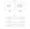
- FIG. 4 is a diagram showing a method of determining an event signal in the controller 220 according to one embodiment.
- (a) and (b) show an n-th frame and an (n+1) -th frame of the images captured by and received from the imaging device, (a) shows the rear side of the vehicle A and (b) shows the rear side of the vehicle A' greater in size than the size of the vehicle A of (a).
- the vehicle A' of the (n+1)-th frame approaches closer than the vehicle A of the n-th frame.
- the image of the (n+1)-th frame of (b) when the vehicle A' and the vehicle A of the n-th frame denoted by a dotted line are compared, pixel change may be confirmed.
- the number of changed pixels is greater than a predetermined range, it may be determined that an event occurs, that is, that another vehicle approaches the back side of the vehicle.
- the second transmitter 230 may send the received signal to the display device of the navigation device 300 provided in front of the driver seat of the vehicle.
- the second transmitter 230 may be a USB.
- the received signal (image data) may be sent to the navigation device 300 via the USB and the wireless reception device 200 may receive power from the navigation device 300 via the USB.
- the navigation device 300 includes a decoder (not shown) for decoding the received signal into an image signal to be displayed. At this time, the navigation device 300 may continuously display the signal received in the reverse mode of the vehicle, and selectively display the signal received in the drive or stop mode (a neutral gear or a park gear) of the vehicle only when an event occurs.
- a decoder not shown
- the controller 220 of the wireless reception device 200 determines whether the received signal is an event signal and sends at least one byte for identifying the mode along with the image signal of the frame when the received signal is the event signal.
- the signal for identifying the mode is distinguished and, when it is determined that the received signal is the event signal, the signal is stored in the memory (not shown) of the navigation device 300 and occurrence of the event is displayed. At this time, occurrence of the event may be displayed by displaying an icon on the display of the navigation device or ringing an alarm bell.
- FIG. 5 is a diagram showing encrypted image information.
- (a) shows data indicating occurrence of an event
- (b) shows data indicating that an event does not occur during driving
- (c) shows data captured in the reverse mode. All received data may be displayed on the navigation device 300.
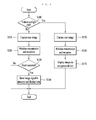
- FIG. 6 is a diagram showing operation of the vehicle rear sensor of FIG. 1 according to one embodiment.
- Whether the taillights of the vehicle are turned on is determined (S100).
- the USB dongle cannot determine whether the vehicle is in a reverse mode.
- the imaging device 100 may determine that the vehicle is in the reverse mode and capture the rear image of the vehicle (S150).
- the rear image may be captured by the image acquisition unit 110 of the imaging device 100 and the captured image may be encoded by the encoder 120.
- the captured image is transmitted by the imaging device 100 and is received by the wireless reception device 200 (S160).
- the first transmitter 140 of the imaging device 100 may transmit the encoded image signal and the receiver 210 of the wireless reception device 200 may receive the signal.
- the controller 220 may send the image signal to the navigation device 300 via the second transmitter 230 without determining whether an event occurs.
- the controller 220 may send all the received data to the navigation device without determining whether an event occurs and the navigation device 300 may display the image signal received via the USB, that is, the rear image of the vehicle captured in the reverse mode (S170).
- the imaging device may capture the rear image of the vehicle (S110).
- the rear image may be captured by the image acquisition unit 110 of the imaging device 100 and the captured image may be encoded by the encoder 120.
- the captured image is transmitted by the imaging device 100 and is received by the wireless reception device 200 (S120).
- the first transmitter 140 of the imaging device 100 may transmit the encoded image signal and the receiver 210 of the wireless reception device 200 may receive the signal.
- the image signal captured and transmitted when the taillights of the vehicle are turned off, that is, when the vehicle is in the drive mode or the stop mode, may not be displayed on the navigation device 300.
- the navigation device 300 may display travel information to a destination or a map.
- the controller 220 may determine whether an event occurs (S130). Whether an event occurs may be determined using pixel change of the image signal in consecutive frames as described with reference to FIG. 4 .
- the wireless reception device 200 does not store or send the received image signal.
- the navigation device 300 may continuously display travel information to a destination or a map.
- the image signal may be sent to the navigation device 300 via the second transmitter 230.
- the navigation device 300 checks the event signal and displays occurrence of the event by displaying an icon on the display or ringing an alarm bell (S140).
- the received image signal may be stored in the memory.
- the driver may confirm the stored image signal by clicking the icon.
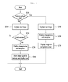
- FIG. 7 is a diagram showing operation of the vehicle rear sensor of FIG. 1 according to another embodiment.
- Operation of the vehicle rear sensor according to the present embodiment is similar to the embodiment of FIG. 6 except that the imaging device determines whether an event occurs.
- Whether the taillights of the vehicle are turned on is determined (S200).
- the rear image of the vehicle is captured (S250).
- the rear image may be captured by the image acquisition unit 110 of the imaging device 100 and the captured image may be encoded by the encoder 120.
- the captured image is transmitted by the imaging device 100 and is received by the wireless reception device 200 (S260).
- the first transmitter 140 of the imaging device 100 may transmit the encoded image signal and the receiver 210 of the wireless reception device 200 may receive the signal.
- the controller 220 may send the image signal to the navigation device 300 via the second transmitter 230 without determining whether an event occurs.
- the controller 220 may send the received data to the navigation device without determining whether an event occurs and the navigation device 300 may display the image signal received via the USB, that is, the rear image of the vehicle captured in the reverse mode (S270).
- the imaging device may capture the rear image of the vehicle (S210).
- the rear image may be captured by the image acquisition unit 110 of the imaging device 100 and the captured image may be encoded by the encoder 120.
- the imaging device 100 may determine whether an event occurs (S220). Whether an event occurs may be determined using pixel change of the image signal in consecutive frames as described above.
- the imaging device 100 should include a controller (not shown).
- the imaging device 100 determines whether an event occurs, the image information may be sent only when the event occurs. Accordingly, when the event occurs, full HD image information may be transmitted instead of VGA image information.
- the captured image signal may not be stored.
- the wireless reception device 200 may not receive the image signal.
- the navigation device 300 may display travel information to a destination or a map.
- the image signal may be encoded and transmitted by the imaging device 100 and may be received by the wireless reception device 200 (S230).
- the first transmitter 140 of the imaging device 100 may transmit the encoded image signal and the receiver 210 of the wireless reception device 200 may receive the signal.
- the image signal may be sent to the navigation device 300 via the second transmitter 230 of the wireless reception device 200.
- the navigation device 300 displays occurrence of the event by displaying an icon on the display or ringing an alarm bell (S240).
- the received image signal may be stored in the memory.
- the driver may confirm the stored image signal by clicking the icon.
- the configuration of the imaging device may become complicated, but only the image signal corresponding to the event is transmitted. Therefore, it is possible to reduce data transmission/reception load between the imaging device and the wireless reception device.
- FIGs. 8a and 8b are diagrams showing connection between a wireless reception device and a navigation device according to one embodiment.
- the wireless reception device 200 shown in FIG. 8a includes a second transmitter 230.
- the second transmitter 230 may be a USB.
- a receiver 310 mounted at one side of the navigation device 300 may be a USB reception port, and a second transmitter 230 of a USB type may be connected to the receiver 310 of a USB reception port type.
- the image signal may be sent in a direction "a" and power may be supplied in a direction "b".
- the wireless reception device 200 shown in FIG. 8b may include an audio/video (A/V) cable 240 in addition to the second transmitter 230.
- the second transmitter may be a USB.
- a receiver 310 mounted at one side of the navigation device 300 may be a USB reception port and an A/V receiver 320 may be further included.
- the second transmitter 230 of a USB type may be connected to the receiver 310 of the USB reception port type and the A/V cable 240 may be connected to the A/V receiver 320.
- the image signal in the drive mode or the stop mode may be sent in a direction "a" and power may be supplied in a direction "b".
- the A/V cable 240 and the A/V receiver 320 may send information only in one direction.
- the rear camera and the navigation device are connected by wire without using the USB and the sensor is included in the navigation device.
- the sensor recognizes the image signal and the display device of the navigation device displays the image signal.
- information related to the image signal may be received via a USB cable without using the sensor.
- the image signal in the reverse mode may be sent from the A/V cable 240 to the A/V receiver 320.
- the controller 220 sends all the received data to the navigation device via the A/V cable 240 without determining whether an event occurs and the navigation device 300 displays the image signal received via the USB, that is, the rear image of the vehicle captured in the reverse mode of the vehicle.
- the image signal captured by the rear camera may be wirelessly sent to the USB dongle and the USB dongle may be connected to the navigation device such that the navigation device displays the rear image of the vehicle.
- a person or object approaching the rear side of the vehicle is determined as an event such that the driver recognizes the event.
- the image corresponding to the event may be stored in the navigation device.
- the rear camera may send an image corresponding to an event and the navigation device may store the image.
Landscapes
- Engineering & Computer Science (AREA)
- Multimedia (AREA)
- Physics & Mathematics (AREA)
- General Physics & Mathematics (AREA)
- Signal Processing (AREA)
- Mechanical Engineering (AREA)
- Theoretical Computer Science (AREA)
- Closed-Circuit Television Systems (AREA)
- Studio Devices (AREA)
- Traffic Control Systems (AREA)
Abstract
Description
- This application claims priority Korean Patent Application No
10-2014-0159899, filed in Korea on November 17, 2014 - Embodiments relate to a vehicle rear sensor and, more particularly, to a device provided at the rear side of a vehicle to capture the rear image of the vehicle, to wirelessly transmit the captured image and to display the captured image on a navigation device located in front of a driver seat.
- In a vehicle traveling at a high speed, it is important to ensure a driving space such that a driver accurately views the front, left, right and rear sides of the vehicle and views a very close position upon parking and stopping.
- That is, the driver should view the distant rear side of the vehicle when the vehicle travels at a high speed and view the position close to the vehicle when parking or stopping the vehicle at a predetermined position.
- The vehicle includes a rear-view mirror mounted inside the vehicle to enable the driver to view the rear side of the vehicle, side-view mirrors mounted outside the vehicle to enable the driver to view the right and left rear sides of the vehicle during driving, and a rear sensor (a proximity sensor, an ultrasonic sensor, etc.) or a rear camera mounted on the rear bumper of the vehicle to sense or capture an invisible object located at a close position upon parking or stopping.
- That is, the side-view mirrors are used to view the distant rear side of the vehicle and to view a passenger seated on the back seat, and the rear sensor or rear camera mounted on the rear bumper is used to sense children or objects which are located at the low rear side of the vehicle and are not viewed via the rear-view mirror and the side-view mirrors to send a warning to the driver.
- However, a conventional vehicle rear camera has the following problems.
- The vehicle rear camera operates when the vehicle is in a reverse mode and receives power from the battery or taillights of the vehicle and is connected to a navigation device by wire to display the rear image of the vehicle on the navigation device upon reversing the vehicle.
- Accordingly, when the rear camera and the navigation device are connected by wire in the vehicle, a separate wire is mounted in the vehicle.
- Even when the vehicle moves forward or stops, the driver needs to recognize a person or object approaching the rear side of the vehicle. However, since the conventional rear camera operates only when the vehicle in a drive mode, it is difficult to recognize the person or object approaching the rear side of the vehicle during driving.
- Embodiments provide a vehicle rear sensor including a vehicle rear camera, which is not connected to a navigation device by wire, and enable a driver to recognize an object approaching the rear side of a vehicle even when the vehicle is in a drive mode.
- In one embodiment, a vehicle rear sensor includes an imaging device including an image acquisition unit, an encoder configured to encode image information captured by the image acquisition unit and a first transmitter configured to transmit the encoded signal, and a wireless reception device including a receiver configured to wirelessly receive a signal, a controller configured to determine whether the received signal is an event signal and a second transmitter configured to send the event signal and the received signal to a display device. The event signal has at least one byte for identifying a mode.
- The imaging device may be provided at a rear side of a vehicle.
- The image acquisition unit may be a vehicle rear camera.
- The controller may compare image information of consecutive frames and display the event signal when change in image information per unit time deviates from a predetermined range.
- When power is applied to taillights of a vehicle, the image information of the imaging device may be continuously sent to the display device.
- The wireless reception device may be a universal serial bus (USB) dongle.
- The second transmitter may be a universal serial bus (USB).
- The wireless reception device may be connected to the display device via an audio/video (A/V) cable.
- The A/V cable may continuously send the image information to the display device when power is applied to taillights of a vehicle.
- The second transmitter may send power from the display device to the wireless reception device.
- In another embodiment, a method of sensing a rear side of a vehicle includes continuously acquiring and wirelessly transmitting image information of a rear side of a vehicle, wirelessly receiving the image information and determining whether the vehicle is in a drive mode or a stop mode, comparing image information of consecutive frames and determining whether an event occurs, when the vehicle is in the drive mode or the stop mode, and sending the image information to a display device along with an event occurrence signal when the event occurs.
- The method may further include storing the sent image information in the display device and outputting the event occurrence signal on the display device as image information and/or sound information.
- When the vehicle is in a reverse mode, the image information of the consecutive frames may be continuously displayed on the display device.
- Whether the vehicle is in the drive mode or the stop mode may be determined in a vehicle rear camera or a wireless reception device.
- When pixel change deviates from a predetermined range, it may be determined that an event occurs.
- In the vehicle rear sensor and method for sensing the rear image according to the embodiment, the image signal captured by the rear camera may be wirelessly sent to the USB dongle and the USB dongle may be connected to the navigation device such that the navigation device displays the rear image of the vehicle.
- In particular, even in the drive mode or the stop mode, a person or object approaching the rear side of the vehicle is determined as an event such that the driver recognizes the event. The image corresponding to the event may be stored in the navigation device. Without using an expensive 2-channel black box, the rear camera may send an image corresponding to an event and the navigation device may store the image.
- Arrangements and embodiments may be described in detail with reference to the following drawings in which like reference numerals refer to like elements and wherein:
-
FIG. 1 is a diagram showing placement of a vehicle rear sensor according to one embodiment; -
FIG. 2 is a diagram showing the configuration of an imaging device ofFIG. 1 ; -
FIG. 3 is a diagram showing the configuration of a wireless reception device ofFIG. 1 ; -
FIG. 4 is a diagram showing a method of determining an event signal in a controller according to one embodiment; -
FIG. 5 is a diagram showing encrypted image information; -
FIG. 6 is a diagram showing operation of the vehicle rear sensor ofFIG. 1 according to one embodiment; -
FIG. 7 is a diagram showing operation of the vehicle rear sensor ofFIG. 1 according to another embodiment; and -
FIGs. 8a and 8b are diagrams showing connection between a wireless reception device and a navigation device according to one embodiment. - Hereinafter, the embodiments will be described with reference to the accompanying drawings, in order to help full understanding of this disclosure. However, the embodiments may be variously modified and the scope of this disclosure is not limited to the below-described embodiments. The embodiments are described to provide full understanding of this disclosure to those skilled in the art.
- The relational terms such as first, second, upper, lower and the like may be used solely to distinguish one entity or element from another entity or element without necessarily requiring or implying any physical or logical relationship or order between such entities or elements.
-
FIG. 1 is a diagram showing placement of a vehicle rear sensor according to one embodiment. - The vehicle rear sensor according to the embodiment includes an
imaging device 100 located on the rear side of a vehicle and awireless reception device 200 for wirelessly receiving image information from theimaging device 100. Anavigation device 300 for receiving and displaying the image information from thewireless reception device 100 may be connected to thewireless reception device 200. -
FIG. 2 is a diagram showing the configuration of an imaging device ofFIG. 1 . - The
imaging device 100 may be a vehicle rear camera and may include apower supply 110, animage acquisition unit 120, anencoder 130 and afirst transmitter 140. - The
power supply 110 receives power from an external device of theimaging device 100. For example, thepower supply 110 may be connected to the battery of the vehicle and may be connected to the electrical wire located at the back side of the vehicle. The conventional rear camera receives power from the taillights of the vehicle. In the embodiment, since thepower supply 110 does not receive current from the taillights of the vehicle, the power supply may continuously receive current even when the vehicle is in a drive mode or a stop mode. - The
image acquisition unit 120 may be a camera and may include a lens provided toward the rear side of the vehicle to capture the rear image of the vehicle. When the engine of the vehicle starts and thepower supply 110 supplies current, theimage acquisition unit 120 may continuously capture the rear image of the vehicle regardless of what gear the vehicle is in. - At this time, the
image acquisition unit 120 may capture a full high definition (HD) image having 1920*1080 pixels. In consideration of data transmission efficiency of the wireless transmission/reception method, theencoder 130 may crop some of the captured image and transmit a VGA image having 800*600 pixels. - The
encoder 130 may encode the image information captured by theimage acquisition unit 120 such that the image information may be wirelessly transmitted. - The
first transmitter 140 transmits the encoded image information to thewireless reception device 200. The wireless communication method may be radio communication, optical wireless communication using infrared rays, visible rays, etc. (laser, LED, etc.), acoustic communication using sound waves or ultrasonic waves, etc. - More specifically, the wireless communication method may be ZigBee, Bluetooth, Wi-Fi, etc. in addition to RFID or NFC. For example, a signal may be transmitted and received at a band of 2.4 GHz.
-
FIG. 3 is a diagram showing the configuration of a wireless reception device ofFIG. 1 . - The
wireless reception device 200 may include areceiver 210 for receiving the transmitted signal, acontroller 220 for determining whether the received signal is an event signal, and asecond transmitter 230 for sending the event signal and the received signal to a display device of thenavigation device 300. For example, thewireless reception device 200 may be a universal serial bus (USB) dongle. When the USB dongle is inserted into the navigation device, an image signal may be sent to the navigation device without a wire connected to the main processor of the navigation device. - The
wireless reception device 200 receives the signal wirelessly transmitted from theimaging device 100 and thecontroller 220 controls operation of thewireless reception device 200 and determines whether the received signal is an event signal. - At this time, whether the received signal is an event signal is determined by comparing images of the consecutive frames and determining whether pixel change deviates from a predetermined range.
- The pixel change may be change in color or brightness of each pixel in consecutive frames.
-
FIG. 4 is a diagram showing a method of determining an event signal in thecontroller 220 according to one embodiment. - (a) and (b) show an n-th frame and an (n+1) -th frame of the images captured by and received from the imaging device, (a) shows the rear side of the vehicle A and (b) shows the rear side of the vehicle A' greater in size than the size of the vehicle A of (a).
- That is, the vehicle A' of the (n+1)-th frame approaches closer than the vehicle A of the n-th frame. In the image of the (n+1)-th frame of (b), when the vehicle A' and the vehicle A of the n-th frame denoted by a dotted line are compared, pixel change may be confirmed. When the number of changed pixels is greater than a predetermined range, it may be determined that an event occurs, that is, that another vehicle approaches the back side of the vehicle.
- The
second transmitter 230 may send the received signal to the display device of thenavigation device 300 provided in front of the driver seat of the vehicle. Thesecond transmitter 230 may be a USB. At this time, the received signal (image data) may be sent to thenavigation device 300 via the USB and thewireless reception device 200 may receive power from thenavigation device 300 via the USB. - The
navigation device 300 includes a decoder (not shown) for decoding the received signal into an image signal to be displayed. At this time, thenavigation device 300 may continuously display the signal received in the reverse mode of the vehicle, and selectively display the signal received in the drive or stop mode (a neutral gear or a park gear) of the vehicle only when an event occurs. - This will now be described in detail. The
controller 220 of thewireless reception device 200 determines whether the received signal is an event signal and sends at least one byte for identifying the mode along with the image signal of the frame when the received signal is the event signal. - That is, when the signal of each frame is transmitted, the byte for identifying the mode of each signal is also sent. In the decoder of the
navigation device 300, the signal for identifying the mode is distinguished and, when it is determined that the received signal is the event signal, the signal is stored in the memory (not shown) of thenavigation device 300 and occurrence of the event is displayed. At this time, occurrence of the event may be displayed by displaying an icon on the display of the navigation device or ringing an alarm bell. -
FIG. 5 is a diagram showing encrypted image information. - For example, (a) shows data indicating occurrence of an event, (b) shows data indicating that an event does not occur during driving, and (c) shows data captured in the reverse mode. All received data may be displayed on the
navigation device 300. -
FIG. 6 is a diagram showing operation of the vehicle rear sensor ofFIG. 1 according to one embodiment. - Whether the taillights of the vehicle are turned on is determined (S100). The USB dongle cannot determine whether the vehicle is in a reverse mode. When the taillights are turned on, the vehicle is in the reverse mode. Therefore, the
imaging device 100 may determine that the vehicle is in the reverse mode and capture the rear image of the vehicle (S150). The rear image may be captured by theimage acquisition unit 110 of theimaging device 100 and the captured image may be encoded by theencoder 120. - The captured image is transmitted by the
imaging device 100 and is received by the wireless reception device 200 (S160). Thefirst transmitter 140 of theimaging device 100 may transmit the encoded image signal and thereceiver 210 of thewireless reception device 200 may receive the signal. At this time, thecontroller 220 may send the image signal to thenavigation device 300 via thesecond transmitter 230 without determining whether an event occurs. - As shown in
FIG. 5(c) , when the data captured in the reverse mode is displayed, thecontroller 220 may send all the received data to the navigation device without determining whether an event occurs and thenavigation device 300 may display the image signal received via the USB, that is, the rear image of the vehicle captured in the reverse mode (S170). - When it is determined that the taillights of the vehicle are turned off (S100), the vehicle is in the drive or stop mode. Even in this case, the imaging device may capture the rear image of the vehicle (S110). The rear image may be captured by the
image acquisition unit 110 of theimaging device 100 and the captured image may be encoded by theencoder 120. - The captured image is transmitted by the
imaging device 100 and is received by the wireless reception device 200 (S120). Thefirst transmitter 140 of theimaging device 100 may transmit the encoded image signal and thereceiver 210 of thewireless reception device 200 may receive the signal. - The image signal captured and transmitted when the taillights of the vehicle are turned off, that is, when the vehicle is in the drive mode or the stop mode, may not be displayed on the
navigation device 300. At this time, thenavigation device 300 may display travel information to a destination or a map. - The
controller 220 may determine whether an event occurs (S130). Whether an event occurs may be determined using pixel change of the image signal in consecutive frames as described with reference toFIG. 4 . - When no event occurs (No), the
wireless reception device 200 does not store or send the received image signal. At this time, thenavigation device 300 may continuously display travel information to a destination or a map. - When an event occurs (Yes), the image signal may be sent to the
navigation device 300 via thesecond transmitter 230. Thenavigation device 300 checks the event signal and displays occurrence of the event by displaying an icon on the display or ringing an alarm bell (S140). The received image signal may be stored in the memory. - The driver may confirm the stored image signal by clicking the icon.
-
FIG. 7 is a diagram showing operation of the vehicle rear sensor ofFIG. 1 according to another embodiment. - Operation of the vehicle rear sensor according to the present embodiment is similar to the embodiment of
FIG. 6 except that the imaging device determines whether an event occurs. - Whether the taillights of the vehicle are turned on is determined (S200). When the taillights are turned on, since the vehicle is in the reverse mode, the rear image of the vehicle is captured (S250). The rear image may be captured by the
image acquisition unit 110 of theimaging device 100 and the captured image may be encoded by theencoder 120. - The captured image is transmitted by the
imaging device 100 and is received by the wireless reception device 200 (S260). Thefirst transmitter 140 of theimaging device 100 may transmit the encoded image signal and thereceiver 210 of thewireless reception device 200 may receive the signal. At this time, thecontroller 220 may send the image signal to thenavigation device 300 via thesecond transmitter 230 without determining whether an event occurs. - As shown in
FIG. 5(c) , when the data captured in the reverse mode is displayed, thecontroller 220 may send the received data to the navigation device without determining whether an event occurs and thenavigation device 300 may display the image signal received via the USB, that is, the rear image of the vehicle captured in the reverse mode (S270). - When it is determined that the taillights of the vehicle are turned off (S200), the vehicle is in the drive or stop mode. Even in this case, the imaging device may capture the rear image of the vehicle (S210). The rear image may be captured by the
image acquisition unit 110 of theimaging device 100 and the captured image may be encoded by theencoder 120. - The
imaging device 100 may determine whether an event occurs (S220). Whether an event occurs may be determined using pixel change of the image signal in consecutive frames as described above. Theimaging device 100 should include a controller (not shown). - In the present embodiment, since the
imaging device 100 determines whether an event occurs, the image information may be sent only when the event occurs. Accordingly, when the event occurs, full HD image information may be transmitted instead of VGA image information. - When no event occurs (No), the captured image signal may not be stored. The
wireless reception device 200 may not receive the image signal. At this time, thenavigation device 300 may display travel information to a destination or a map. - When an event occurs (Yes), the image signal may be encoded and transmitted by the
imaging device 100 and may be received by the wireless reception device 200 (S230). Thefirst transmitter 140 of theimaging device 100 may transmit the encoded image signal and thereceiver 210 of thewireless reception device 200 may receive the signal. - The image signal may be sent to the
navigation device 300 via thesecond transmitter 230 of thewireless reception device 200. Thenavigation device 300 displays occurrence of the event by displaying an icon on the display or ringing an alarm bell (S240). The received image signal may be stored in the memory. - The driver may confirm the stored image signal by clicking the icon.
- In the present embodiment, since the event is confirmed in the imaging device by comparing pixels in the image signals of the consecutive frames, the configuration of the imaging device may become complicated, but only the image signal corresponding to the event is transmitted. Therefore, it is possible to reduce data transmission/reception load between the imaging device and the wireless reception device.
-
FIGs. 8a and 8b are diagrams showing connection between a wireless reception device and a navigation device according to one embodiment. - The
wireless reception device 200 shown inFIG. 8a includes asecond transmitter 230. Thesecond transmitter 230 may be a USB. Areceiver 310 mounted at one side of thenavigation device 300 may be a USB reception port, and asecond transmitter 230 of a USB type may be connected to thereceiver 310 of a USB reception port type. At this time, the image signal may be sent in a direction "a" and power may be supplied in a direction "b". - The
wireless reception device 200 shown inFIG. 8b may include an audio/video (A/V)cable 240 in addition to thesecond transmitter 230. The second transmitter may be a USB. Areceiver 310 mounted at one side of thenavigation device 300 may be a USB reception port and an A/V receiver 320 may be further included. - The
second transmitter 230 of a USB type may be connected to thereceiver 310 of the USB reception port type and the A/V cable 240 may be connected to the A/V receiver 320. At this time, the image signal in the drive mode or the stop mode may be sent in a direction "a" and power may be supplied in a direction "b". - Although the
second transmitter 230 and thereceiver 310 using the USB send information in both directions, the A/V cable 240 and the A/V receiver 320 may send information only in one direction. - Conventionally, the rear camera and the navigation device are connected by wire without using the USB and the sensor is included in the navigation device. In this case, when an image signal is received from the A/V cable, the sensor recognizes the image signal and the display device of the navigation device displays the image signal. In contrast, in the present embodiment, information related to the image signal may be received via a USB cable without using the sensor.
- The image signal in the reverse mode may be sent from the A/
V cable 240 to the A/V receiver 320. For example, as shown inFIG. 5(c) , when data captured in the reverse mode is displayed, thecontroller 220 sends all the received data to the navigation device via the A/V cable 240 without determining whether an event occurs and thenavigation device 300 displays the image signal received via the USB, that is, the rear image of the vehicle captured in the reverse mode of the vehicle. - In the vehicle rear sensor and method for sensing the rear image according to the embodiment, the image signal captured by the rear camera may be wirelessly sent to the USB dongle and the USB dongle may be connected to the navigation device such that the navigation device displays the rear image of the vehicle.
- In particular, even in the drive mode or the stop mode, a person or object approaching the rear side of the vehicle is determined as an event such that the driver recognizes the event. The image corresponding to the event may be stored in the navigation device. Without using an expensive 2-channel black box, the rear camera may send an image corresponding to an event and the navigation device may store the image.
- Although embodiments have been described with reference to a number of illustrative embodiments thereof, it should be understood that numerous other modifications and embodiments can be devised by those skilled in the art that will fall within the spirit and scope of the principles of this disclosure. More particularly, various variations and modifications are possible in the component parts and/or arrangements of the subject combination arrangement within the scope of the disclosure, the drawings and the appended claims. In addition to variations and modifications in the component parts and/or arrangements, alternative uses will also be apparent to those skilled in the art.
Claims (15)
- A vehicle rear sensor comprising:an imaging device including an image acquisition unit, an encoder configured to encode image information captured by the image acquisition unit and a first transmitter configured to transmit the encoded signal; anda wireless reception device including a receiver configured to wirelessly receive a signal, a controller configured to determine whether the received signal is an event signal and a second transmitter configured to send the event signal and the received signal to a display device,wherein the event signal has at least one byte for identifying a mode.
- The vehicle rear sensor according to claim 1,
wherein the controller compares image information of consecutive frames and displays the event signal when change in image information per unit time deviates from a predetermined range. - The vehicle rear sensor according to claim 1 or 2, wherein the second transmitter is a universal serial bus (USB).
- The vehicle rear sensor according to any one of claim 1 to 3, further comprising an audio/video (A/V) cable connected to the display device.
- The vehicle rear sensor according to claim 4,
wherein the signal is an image signal captured by a rear camera of a vehicle and the A/V cable continuously sends the image information to the display device when power is applied to taillights of the vehicle. - The vehicle rear sensor according to any one of claim 1 to 5, wherein the second transmitter sends power from the display device to the wireless reception device.
- The vehicle rear sensor according to any one of claim 1 to 6, wherein the imaging device is provided at a rear side of a vehicle.
- The vehicle rear sensor according to any one of claim 1 to 7, wherein the image acquisition unit is a vehicle rear camera.
- The vehicle rear sensor according to any one of claim 1 to 8, wherein, when power is applied to taillights of a vehicle, the image information of the imaging device is continuously sent to the display device.
- The vehicle rear sensor according to any one of claim 1 to 9, wherein the wireless reception device is a universal serial bus (USB) dongle.
- A method of sensing a rear side of a vehicle, the method comprising:continuously acquiring and wirelessly transmitting image information of a rear side of a vehicle;wirelessly receiving the image information and determining whether the vehicle is in a drive mode or a stop mode;comparing image information of consecutive frames and determining whether an event occurs, when the vehicle is in the drive mode or the stop mode; andsending the image information to a display device along with an event occurrence signal when the event occurs.
- The method according to claim 11, further comprising storing the sent image information in the display device and outputting the event occurrence signal on the display device as image information and/or sound information.
- The method according to claim 11 or 12, wherein, when the vehicle is in a reverse mode, the image information of the consecutive frames is continuously displayed on the display device.
- The method according to any one of claim 11 to 13, wherein whether the vehicle is in the drive mode or the stop mode is determined in a vehicle rear camera or a wireless reception device.
- The method according to any one of claim 11 to 14, wherein whether an event signal is generated or not is determined by determining whether pixel change deviates from a predetermined range.
Applications Claiming Priority (1)
| Application Number | Priority Date | Filing Date | Title |
|---|---|---|---|
| KR1020140159899A KR102268106B1 (en) | 2014-11-17 | 2014-11-17 | Wireless signal receiving unit, rear sensor for vehicle and method for sensing rear |
Publications (2)
| Publication Number | Publication Date |
|---|---|
| EP3021576A1 true EP3021576A1 (en) | 2016-05-18 |
| EP3021576B1 EP3021576B1 (en) | 2018-01-10 |
Family
ID=54548045
Family Applications (1)
| Application Number | Title | Priority Date | Filing Date |
|---|---|---|---|
| EP15194251.3A Active EP3021576B1 (en) | 2014-11-17 | 2015-11-12 | Wireless reception device, vehicle rear sensor including the same and method for sensing rear image |
Country Status (4)
| Country | Link |
|---|---|
| US (1) | US20160137128A1 (en) |
| EP (1) | EP3021576B1 (en) |
| KR (1) | KR102268106B1 (en) |
| CN (1) | CN105599701A (en) |
Cited By (1)
| Publication number | Priority date | Publication date | Assignee | Title |
|---|---|---|---|---|
| CN113632412A (en) * | 2019-03-26 | 2021-11-09 | 株式会社小糸制作所 | Automobile and vehicle lamp |
Families Citing this family (2)
| Publication number | Priority date | Publication date | Assignee | Title |
|---|---|---|---|---|
| KR20180061738A (en) | 2016-11-30 | 2018-06-08 | 쌍용자동차 주식회사 | Parking guide method for vehicle backward |
| US10339392B2 (en) * | 2017-06-15 | 2019-07-02 | Blackberry Limited | Method and system for rear status detection |
Citations (2)
| Publication number | Priority date | Publication date | Assignee | Title |
|---|---|---|---|---|
| US20090244282A1 (en) * | 2008-04-01 | 2009-10-01 | Francisco Jose Eguiguren | Vehicle camera system |
| CN201914177U (en) * | 2010-11-16 | 2011-08-03 | 河南省电力公司平顶山供电公司 | Wireless visible vehicle back running display device |
Family Cites Families (12)
| Publication number | Priority date | Publication date | Assignee | Title |
|---|---|---|---|---|
| JP4561479B2 (en) * | 2005-05-26 | 2010-10-13 | アイシン・エィ・ダブリュ株式会社 | Parking support method and parking support device |
| KR100845193B1 (en) * | 2007-08-27 | 2008-07-10 | 정대철 | Rear monitoring system of vehicle using wireless communication |
| KR100946160B1 (en) * | 2008-10-15 | 2010-03-11 | 애로우윙즈 주식회사 | Rear monitoring unit for vehicle, rear monitoring apparatus for vehicle therewith |
| US8174375B2 (en) * | 2009-06-30 | 2012-05-08 | The Hong Kong Polytechnic University | Detection system for assisting a driver when driving a vehicle using a plurality of image capturing devices |
| EP2473871B1 (en) * | 2009-09-01 | 2015-03-11 | Magna Mirrors Of America, Inc. | Imaging and display system for vehicle |
| KR101072346B1 (en) * | 2010-01-20 | 2011-10-11 | 엠텍비젼 주식회사 | Video recording apparatus for vehicle and operation mode controlling method thereof |
| DE102010033875B4 (en) * | 2010-08-10 | 2013-07-18 | Daimler Ag | Guide rail for a sliding roof system and method for producing such a guide rail |
| US9443152B2 (en) * | 2011-05-03 | 2016-09-13 | Ionroad Technologies Ltd. | Automatic image content analysis method and system |
| KR101476678B1 (en) * | 2012-10-22 | 2014-12-26 | 소치재 | Transmission system for mirror integrated camera of vehicle and control method thereof |
| CN203186238U (en) * | 2013-02-27 | 2013-09-11 | 深圳市微高半导体科技有限公司 | Vehicle-mounted side-looking wireless camera |
| KR101482171B1 (en) * | 2013-09-05 | 2015-01-13 | 현대모비스(주) | Control method for around view stop mode |
| US20150329045A1 (en) * | 2014-05-15 | 2015-11-19 | Fritz B. Harris | Vehcile detection and warning system |
-
2014
- 2014-11-17 KR KR1020140159899A patent/KR102268106B1/en active Active
-
2015
- 2015-11-12 EP EP15194251.3A patent/EP3021576B1/en active Active
- 2015-11-17 US US14/943,325 patent/US20160137128A1/en not_active Abandoned
- 2015-11-17 CN CN201510794403.2A patent/CN105599701A/en active Pending
Patent Citations (2)
| Publication number | Priority date | Publication date | Assignee | Title |
|---|---|---|---|---|
| US20090244282A1 (en) * | 2008-04-01 | 2009-10-01 | Francisco Jose Eguiguren | Vehicle camera system |
| CN201914177U (en) * | 2010-11-16 | 2011-08-03 | 河南省电力公司平顶山供电公司 | Wireless visible vehicle back running display device |
Cited By (1)
| Publication number | Priority date | Publication date | Assignee | Title |
|---|---|---|---|---|
| CN113632412A (en) * | 2019-03-26 | 2021-11-09 | 株式会社小糸制作所 | Automobile and vehicle lamp |
Also Published As
| Publication number | Publication date |
|---|---|
| KR102268106B1 (en) | 2021-06-22 |
| EP3021576B1 (en) | 2018-01-10 |
| CN105599701A (en) | 2016-05-25 |
| KR20160058443A (en) | 2016-05-25 |
| US20160137128A1 (en) | 2016-05-19 |
Similar Documents
| Publication | Publication Date | Title |
|---|---|---|
| US6989739B2 (en) | Vehicular monitoring systems with a multi-window display | |
| CN105308620B (en) | Information processing apparatus, proximity object notification method, and program | |
| US12391182B2 (en) | Auto-switch display intelligent rearview mirror system | |
| US11027654B2 (en) | Vehicle vision system with compressed video transfer via DSRC link | |
| US20160127693A1 (en) | WiFi Wireless Rear View Parking System | |
| US20180015879A1 (en) | Side-view mirror camera system for vehicle | |
| TWI557003B (en) | Image based intelligent security system for vehicle combined with sensor | |
| EP3021576B1 (en) | Wireless reception device, vehicle rear sensor including the same and method for sensing rear image | |
| JP2005222307A (en) | Image display system and image display method | |
| WO2014070276A4 (en) | System and method for providing front-oriented visual information to vehicle driver | |
| US11135883B2 (en) | Vehicular sensing system with ultrasonic sensor at trailer hitch | |
| US12487355B2 (en) | Vehicular driving assist system using radar and communication with other vehicles | |
| US9121944B2 (en) | Mid-infrared vehicle early warning system | |
| US20170320435A1 (en) | WiFi Wireless Rear View Parking System | |
| US10486598B2 (en) | Vehicular image-display system | |
| JP2014208521A (en) | On-vehicle image monitoring system and communication connection method for on-vehicle image monitoring system | |
| CN209852185U (en) | Streaming media rearview mirror device with DVR and vehicle system | |
| US20160259982A1 (en) | Vehicle view monitoring system | |
| US20160073051A1 (en) | Driving recorder and driving recording method | |
| KR20180013126A (en) | Black-box for vehicle | |
| KR102536826B1 (en) | Apparatus and method for driving information of a car, and program recorded on a recording medium performing the method | |
| US20250100461A1 (en) | Electronic device for providing blind spot image through pillar of vehicle and operating method of the same | |
| US20250091513A1 (en) | Electronic device for performing integrated multi-functions using single rear view image of vehicle, and operating method of the same | |
| US20250153640A1 (en) | Digital rear mirror for detecting blind-spot vehicle or parking area based on rear image of vehicle and operating method of the same | |
| KR20200082317A (en) | Video processing apparatus and operating method for the same |
Legal Events
| Date | Code | Title | Description |
|---|---|---|---|
| PUAI | Public reference made under article 153(3) epc to a published international application that has entered the european phase |
Free format text: ORIGINAL CODE: 0009012 |
|
| AK | Designated contracting states |
Kind code of ref document: A1 Designated state(s): AL AT BE BG CH CY CZ DE DK EE ES FI FR GB GR HR HU IE IS IT LI LT LU LV MC MK MT NL NO PL PT RO RS SE SI SK SM TR |
|
| AX | Request for extension of the european patent |
Extension state: BA ME |
|
| 17P | Request for examination filed |
Effective date: 20161109 |
|
| RBV | Designated contracting states (corrected) |
Designated state(s): AL AT BE BG CH CY CZ DE DK EE ES FI FR GB GR HR HU IE IS IT LI LT LU LV MC MK MT NL NO PL PT RO RS SE SI SK SM TR |
|
| RAP1 | Party data changed (applicant data changed or rights of an application transferred) |
Owner name: LG INNOTEK CO., LTD. |
|
| GRAP | Despatch of communication of intention to grant a patent |
Free format text: ORIGINAL CODE: EPIDOSNIGR1 |
|
| INTG | Intention to grant announced |
Effective date: 20170801 |
|
| GRAS | Grant fee paid |
Free format text: ORIGINAL CODE: EPIDOSNIGR3 |
|
| GRAA | (expected) grant |
Free format text: ORIGINAL CODE: 0009210 |
|
| AK | Designated contracting states |
Kind code of ref document: B1 Designated state(s): AL AT BE BG CH CY CZ DE DK EE ES FI FR GB GR HR HU IE IS IT LI LT LU LV MC MK MT NL NO PL PT RO RS SE SI SK SM TR |
|
| REG | Reference to a national code |
Ref country code: CH Ref legal event code: EP Ref country code: AT Ref legal event code: REF Ref document number: 963646 Country of ref document: AT Kind code of ref document: T Effective date: 20180115 |
|
| REG | Reference to a national code |
Ref country code: IE Ref legal event code: FG4D |
|
| REG | Reference to a national code |
Ref country code: DE Ref legal event code: R096 Ref document number: 602015007319 Country of ref document: DE |
|
| REG | Reference to a national code |
Ref country code: NL Ref legal event code: MP Effective date: 20180110 |
|
| REG | Reference to a national code |
Ref country code: AT Ref legal event code: MK05 Ref document number: 963646 Country of ref document: AT Kind code of ref document: T Effective date: 20180110 |
|
| PG25 | Lapsed in a contracting state [announced via postgrant information from national office to epo] |
Ref country code: NL Free format text: LAPSE BECAUSE OF FAILURE TO SUBMIT A TRANSLATION OF THE DESCRIPTION OR TO PAY THE FEE WITHIN THE PRESCRIBED TIME-LIMIT Effective date: 20180110 |
|
| PG25 | Lapsed in a contracting state [announced via postgrant information from national office to epo] |
Ref country code: ES Free format text: LAPSE BECAUSE OF FAILURE TO SUBMIT A TRANSLATION OF THE DESCRIPTION OR TO PAY THE FEE WITHIN THE PRESCRIBED TIME-LIMIT Effective date: 20180110 Ref country code: HR Free format text: LAPSE BECAUSE OF FAILURE TO SUBMIT A TRANSLATION OF THE DESCRIPTION OR TO PAY THE FEE WITHIN THE PRESCRIBED TIME-LIMIT Effective date: 20180110 Ref country code: NO Free format text: LAPSE BECAUSE OF FAILURE TO SUBMIT A TRANSLATION OF THE DESCRIPTION OR TO PAY THE FEE WITHIN THE PRESCRIBED TIME-LIMIT Effective date: 20180410 Ref country code: FI Free format text: LAPSE BECAUSE OF FAILURE TO SUBMIT A TRANSLATION OF THE DESCRIPTION OR TO PAY THE FEE WITHIN THE PRESCRIBED TIME-LIMIT Effective date: 20180110 Ref country code: LT Free format text: LAPSE BECAUSE OF FAILURE TO SUBMIT A TRANSLATION OF THE DESCRIPTION OR TO PAY THE FEE WITHIN THE PRESCRIBED TIME-LIMIT Effective date: 20180110 Ref country code: CY Free format text: LAPSE BECAUSE OF FAILURE TO SUBMIT A TRANSLATION OF THE DESCRIPTION OR TO PAY THE FEE WITHIN THE PRESCRIBED TIME-LIMIT Effective date: 20180110 |
|
| PG25 | Lapsed in a contracting state [announced via postgrant information from national office to epo] |
Ref country code: GR Free format text: LAPSE BECAUSE OF FAILURE TO SUBMIT A TRANSLATION OF THE DESCRIPTION OR TO PAY THE FEE WITHIN THE PRESCRIBED TIME-LIMIT Effective date: 20180411 Ref country code: SE Free format text: LAPSE BECAUSE OF FAILURE TO SUBMIT A TRANSLATION OF THE DESCRIPTION OR TO PAY THE FEE WITHIN THE PRESCRIBED TIME-LIMIT Effective date: 20180110 Ref country code: IS Free format text: LAPSE BECAUSE OF FAILURE TO SUBMIT A TRANSLATION OF THE DESCRIPTION OR TO PAY THE FEE WITHIN THE PRESCRIBED TIME-LIMIT Effective date: 20180510 Ref country code: LV Free format text: LAPSE BECAUSE OF FAILURE TO SUBMIT A TRANSLATION OF THE DESCRIPTION OR TO PAY THE FEE WITHIN THE PRESCRIBED TIME-LIMIT Effective date: 20180110 Ref country code: PL Free format text: LAPSE BECAUSE OF FAILURE TO SUBMIT A TRANSLATION OF THE DESCRIPTION OR TO PAY THE FEE WITHIN THE PRESCRIBED TIME-LIMIT Effective date: 20180110 Ref country code: RS Free format text: LAPSE BECAUSE OF FAILURE TO SUBMIT A TRANSLATION OF THE DESCRIPTION OR TO PAY THE FEE WITHIN THE PRESCRIBED TIME-LIMIT Effective date: 20180110 Ref country code: BG Free format text: LAPSE BECAUSE OF FAILURE TO SUBMIT A TRANSLATION OF THE DESCRIPTION OR TO PAY THE FEE WITHIN THE PRESCRIBED TIME-LIMIT Effective date: 20180410 Ref country code: AT Free format text: LAPSE BECAUSE OF FAILURE TO SUBMIT A TRANSLATION OF THE DESCRIPTION OR TO PAY THE FEE WITHIN THE PRESCRIBED TIME-LIMIT Effective date: 20180110 |
|
| REG | Reference to a national code |
Ref country code: FR Ref legal event code: PLFP Year of fee payment: 4 |
|
| REG | Reference to a national code |
Ref country code: DE Ref legal event code: R097 Ref document number: 602015007319 Country of ref document: DE |
|
| PG25 | Lapsed in a contracting state [announced via postgrant information from national office to epo] |
Ref country code: IT Free format text: LAPSE BECAUSE OF FAILURE TO SUBMIT A TRANSLATION OF THE DESCRIPTION OR TO PAY THE FEE WITHIN THE PRESCRIBED TIME-LIMIT Effective date: 20180110 Ref country code: RO Free format text: LAPSE BECAUSE OF FAILURE TO SUBMIT A TRANSLATION OF THE DESCRIPTION OR TO PAY THE FEE WITHIN THE PRESCRIBED TIME-LIMIT Effective date: 20180110 Ref country code: EE Free format text: LAPSE BECAUSE OF FAILURE TO SUBMIT A TRANSLATION OF THE DESCRIPTION OR TO PAY THE FEE WITHIN THE PRESCRIBED TIME-LIMIT Effective date: 20180110 Ref country code: AL Free format text: LAPSE BECAUSE OF FAILURE TO SUBMIT A TRANSLATION OF THE DESCRIPTION OR TO PAY THE FEE WITHIN THE PRESCRIBED TIME-LIMIT Effective date: 20180110 |
|
| PLBE | No opposition filed within time limit |
Free format text: ORIGINAL CODE: 0009261 |
|
| STAA | Information on the status of an ep patent application or granted ep patent |
Free format text: STATUS: NO OPPOSITION FILED WITHIN TIME LIMIT |
|
| PG25 | Lapsed in a contracting state [announced via postgrant information from national office to epo] |
Ref country code: DK Free format text: LAPSE BECAUSE OF FAILURE TO SUBMIT A TRANSLATION OF THE DESCRIPTION OR TO PAY THE FEE WITHIN THE PRESCRIBED TIME-LIMIT Effective date: 20180110 Ref country code: SK Free format text: LAPSE BECAUSE OF FAILURE TO SUBMIT A TRANSLATION OF THE DESCRIPTION OR TO PAY THE FEE WITHIN THE PRESCRIBED TIME-LIMIT Effective date: 20180110 Ref country code: CZ Free format text: LAPSE BECAUSE OF FAILURE TO SUBMIT A TRANSLATION OF THE DESCRIPTION OR TO PAY THE FEE WITHIN THE PRESCRIBED TIME-LIMIT Effective date: 20180110 Ref country code: SM Free format text: LAPSE BECAUSE OF FAILURE TO SUBMIT A TRANSLATION OF THE DESCRIPTION OR TO PAY THE FEE WITHIN THE PRESCRIBED TIME-LIMIT Effective date: 20180110 |
|
| 26N | No opposition filed |
Effective date: 20181011 |
|
| PG25 | Lapsed in a contracting state [announced via postgrant information from national office to epo] |
Ref country code: SI Free format text: LAPSE BECAUSE OF FAILURE TO SUBMIT A TRANSLATION OF THE DESCRIPTION OR TO PAY THE FEE WITHIN THE PRESCRIBED TIME-LIMIT Effective date: 20180110 |
|
| REG | Reference to a national code |
Ref country code: CH Ref legal event code: PL |
|
| PG25 | Lapsed in a contracting state [announced via postgrant information from national office to epo] |
Ref country code: LU Free format text: LAPSE BECAUSE OF NON-PAYMENT OF DUE FEES Effective date: 20181112 Ref country code: MC Free format text: LAPSE BECAUSE OF FAILURE TO SUBMIT A TRANSLATION OF THE DESCRIPTION OR TO PAY THE FEE WITHIN THE PRESCRIBED TIME-LIMIT Effective date: 20180110 |
|
| REG | Reference to a national code |
Ref country code: BE Ref legal event code: MM Effective date: 20181130 |
|
| REG | Reference to a national code |
Ref country code: IE Ref legal event code: MM4A |
|
| PG25 | Lapsed in a contracting state [announced via postgrant information from national office to epo] |
Ref country code: LI Free format text: LAPSE BECAUSE OF NON-PAYMENT OF DUE FEES Effective date: 20181130 Ref country code: CH Free format text: LAPSE BECAUSE OF NON-PAYMENT OF DUE FEES Effective date: 20181130 |
|
| PG25 | Lapsed in a contracting state [announced via postgrant information from national office to epo] |
Ref country code: IE Free format text: LAPSE BECAUSE OF NON-PAYMENT OF DUE FEES Effective date: 20181112 |
|
| PG25 | Lapsed in a contracting state [announced via postgrant information from national office to epo] |
Ref country code: BE Free format text: LAPSE BECAUSE OF NON-PAYMENT OF DUE FEES Effective date: 20181130 |
|
| PG25 | Lapsed in a contracting state [announced via postgrant information from national office to epo] |
Ref country code: MT Free format text: LAPSE BECAUSE OF NON-PAYMENT OF DUE FEES Effective date: 20181112 |
|
| PG25 | Lapsed in a contracting state [announced via postgrant information from national office to epo] |
Ref country code: TR Free format text: LAPSE BECAUSE OF FAILURE TO SUBMIT A TRANSLATION OF THE DESCRIPTION OR TO PAY THE FEE WITHIN THE PRESCRIBED TIME-LIMIT Effective date: 20180110 |
|
| PG25 | Lapsed in a contracting state [announced via postgrant information from national office to epo] |
Ref country code: PT Free format text: LAPSE BECAUSE OF FAILURE TO SUBMIT A TRANSLATION OF THE DESCRIPTION OR TO PAY THE FEE WITHIN THE PRESCRIBED TIME-LIMIT Effective date: 20180110 |
|
| PG25 | Lapsed in a contracting state [announced via postgrant information from national office to epo] |
Ref country code: HU Free format text: LAPSE BECAUSE OF FAILURE TO SUBMIT A TRANSLATION OF THE DESCRIPTION OR TO PAY THE FEE WITHIN THE PRESCRIBED TIME-LIMIT; INVALID AB INITIO Effective date: 20151112 Ref country code: MK Free format text: LAPSE BECAUSE OF NON-PAYMENT OF DUE FEES Effective date: 20180110 |
|
| PGFP | Annual fee paid to national office [announced via postgrant information from national office to epo] |
Ref country code: DE Payment date: 20241021 Year of fee payment: 10 |
|
| PGFP | Annual fee paid to national office [announced via postgrant information from national office to epo] |
Ref country code: GB Payment date: 20241021 Year of fee payment: 10 |
|
| PGFP | Annual fee paid to national office [announced via postgrant information from national office to epo] |
Ref country code: FR Payment date: 20241022 Year of fee payment: 10 |