EP3021513A1 - Apparatuses and methods for logic channel prioritization - Google Patents
Apparatuses and methods for logic channel prioritization Download PDFInfo
- Publication number
- EP3021513A1 EP3021513A1 EP15194911.2A EP15194911A EP3021513A1 EP 3021513 A1 EP3021513 A1 EP 3021513A1 EP 15194911 A EP15194911 A EP 15194911A EP 3021513 A1 EP3021513 A1 EP 3021513A1
- Authority
- EP
- European Patent Office
- Prior art keywords
- uplink data
- uplink
- resource assignments
- uplink resource
- mobile communication
- Prior art date
- Legal status (The legal status is an assumption and is not a legal conclusion. Google has not performed a legal analysis and makes no representation as to the accuracy of the status listed.)
- Withdrawn
Links
Images


Classifications
-
- H—ELECTRICITY
- H04—ELECTRIC COMMUNICATION TECHNIQUE
- H04L—TRANSMISSION OF DIGITAL INFORMATION, e.g. TELEGRAPHIC COMMUNICATION
- H04L5/00—Arrangements affording multiple use of the transmission path
- H04L5/0001—Arrangements for dividing the transmission path
- H04L5/0003—Two-dimensional division
- H04L5/0005—Time-frequency
- H04L5/0007—Time-frequency the frequencies being orthogonal, e.g. OFDM(A) or DMT
- H04L5/001—Time-frequency the frequencies being orthogonal, e.g. OFDM(A) or DMT the frequencies being arranged in component carriers
-
- H—ELECTRICITY
- H04—ELECTRIC COMMUNICATION TECHNIQUE
- H04L—TRANSMISSION OF DIGITAL INFORMATION, e.g. TELEGRAPHIC COMMUNICATION
- H04L5/00—Arrangements affording multiple use of the transmission path
- H04L5/0091—Signalling for the administration of the divided path, e.g. signalling of configuration information
-
- H—ELECTRICITY
- H04—ELECTRIC COMMUNICATION TECHNIQUE
- H04L—TRANSMISSION OF DIGITAL INFORMATION, e.g. TELEGRAPHIC COMMUNICATION
- H04L1/00—Arrangements for detecting or preventing errors in the information received
- H04L1/12—Arrangements for detecting or preventing errors in the information received by using return channel
- H04L1/16—Arrangements for detecting or preventing errors in the information received by using return channel in which the return channel carries supervisory signals, e.g. repetition request signals
- H04L1/1607—Details of the supervisory signal
- H04L1/1671—Details of the supervisory signal the supervisory signal being transmitted together with control information
-
- H—ELECTRICITY
- H04—ELECTRIC COMMUNICATION TECHNIQUE
- H04L—TRANSMISSION OF DIGITAL INFORMATION, e.g. TELEGRAPHIC COMMUNICATION
- H04L1/00—Arrangements for detecting or preventing errors in the information received
- H04L1/12—Arrangements for detecting or preventing errors in the information received by using return channel
- H04L1/16—Arrangements for detecting or preventing errors in the information received by using return channel in which the return channel carries supervisory signals, e.g. repetition request signals
- H04L1/18—Automatic repetition systems, e.g. Van Duuren systems
- H04L1/1829—Arrangements specially adapted for the receiver end
- H04L1/1864—ARQ related signaling
-
- H—ELECTRICITY
- H04—ELECTRIC COMMUNICATION TECHNIQUE
- H04L—TRANSMISSION OF DIGITAL INFORMATION, e.g. TELEGRAPHIC COMMUNICATION
- H04L5/00—Arrangements affording multiple use of the transmission path
- H04L5/003—Arrangements for allocating sub-channels of the transmission path
-
- H—ELECTRICITY
- H04—ELECTRIC COMMUNICATION TECHNIQUE
- H04L—TRANSMISSION OF DIGITAL INFORMATION, e.g. TELEGRAPHIC COMMUNICATION
- H04L5/00—Arrangements affording multiple use of the transmission path
- H04L5/003—Arrangements for allocating sub-channels of the transmission path
- H04L5/0044—Allocation of payload; Allocation of data channels, e.g. PDSCH or PUSCH
-
- H—ELECTRICITY
- H04—ELECTRIC COMMUNICATION TECHNIQUE
- H04L—TRANSMISSION OF DIGITAL INFORMATION, e.g. TELEGRAPHIC COMMUNICATION
- H04L5/00—Arrangements affording multiple use of the transmission path
- H04L5/003—Arrangements for allocating sub-channels of the transmission path
- H04L5/0058—Allocation criteria
- H04L5/006—Quality of the received signal, e.g. BER, SNR, water filling
-
- H—ELECTRICITY
- H04—ELECTRIC COMMUNICATION TECHNIQUE
- H04L—TRANSMISSION OF DIGITAL INFORMATION, e.g. TELEGRAPHIC COMMUNICATION
- H04L5/00—Arrangements affording multiple use of the transmission path
- H04L5/0091—Signalling for the administration of the divided path, e.g. signalling of configuration information
- H04L5/0094—Indication of how sub-channels of the path are allocated
-
- H—ELECTRICITY
- H04—ELECTRIC COMMUNICATION TECHNIQUE
- H04W—WIRELESS COMMUNICATION NETWORKS
- H04W72/00—Local resource management
- H04W72/20—Control channels or signalling for resource management
- H04W72/21—Control channels or signalling for resource management in the uplink direction of a wireless link, i.e. towards the network
-
- H—ELECTRICITY
- H04—ELECTRIC COMMUNICATION TECHNIQUE
- H04W—WIRELESS COMMUNICATION NETWORKS
- H04W72/00—Local resource management
- H04W72/50—Allocation or scheduling criteria for wireless resources
- H04W72/56—Allocation or scheduling criteria for wireless resources based on priority criteria
Definitions
- the application generally relates to logic channel prioritization, and more particularly, to logic channel prioritization for multiple component carriers.
- GSM Global System for Mobile communications
- GPRS General Packet Radio Service
- EDGE Enhanced Data rates for Global Evolution
- WCDMA Wideband Code Division Multiple Access
- CDMA2000 Code Division Multiple Access 2000
- TD-SCDMA Time Division-Synchronous Code Division Multiple Access
- WiMAX Worldwide Interoperability for Microwave Access
- LTE Long Term Evolution
- TD-LTE Time- Division LTE
- LTE-A LTE-Advanced
- a User Equipment supports only a single carrier transmission and reception.
- An LTE network may assign uplink resources on the signal component carrier for the UE to transmit uplink data, and the UE has to perform a logical channel prioritization procedure to properly allocate the uplink resource assignments for uplink data transmissions on the single component carrier according to the priority levels of each radio bearer and predetermined bucket size.
- CA Carrier Aggregation
- a UE may be assigned with uplink resources for each component carrier.
- LTE-A technology in compliance with the 3GPP TS 36.321, release 10 specification as an example; when the UE is requested to transmit multiple Medium Access Control (MAC) Packet Data Units (PDUs) over several component carriers in one Transmission Time Interval (TTI), it may apply the same logical channel prioritization procedure as defined for the single carrier scenario to the uplink resource assignments of each component carrier independently, or to the sum of the uplink resource assignments of all component carriers.
- MAC Medium Access Control
- PDUs Packet Data Units
- TTI Transmission Time Interval
- a mobile communication device comprising a wireless transceiver and a controller.
- the wireless transceiver is configured to perform wireless transmission and reception to and from a service network via a plurality of component carriers.
- the controller is configured to determine a plurality of service levels, each corresponding to a respective one of the component carriers, and allocate uplink resource assignments for uplink data transmissions according to the service levels and traffic type of the uplink data.
- a method for logic channel prioritization which is executed by a mobile communication device wirelessly communicating with a service network via a plurality of component carriers.
- the method comprises the steps of: determining a plurality of service levels, each corresponding to a respective one of the component carriers; and allocating uplink resource assignments for uplink data transmissions according to the service levels and traffic type of the uplink data.
- Fig. 1 is a block diagram of a wireless communication environment according to an embodiment of the invention.
- the wireless communication environment 100 comprises a mobile communication device 110 and a service network 120, wherein the mobile communication device 110 supports multiple component carriers and is wirelessly connected to the service network 120 for obtaining mobile services.
- the mobile communication device 110 may be a feature phone, a smartphone, a panel Personal Computer (PC), a laptop computer, or any computing device supporting the wireless technology utilized by the service network 120.
- the service network 120 may be a cellular network supporting multiple component carriers, such as an LTE-A network.
- the service network 120 comprises an access network 121 and a core network 122, wherein the access network 121 is responsible for processing radio signals, terminating radio protocols, and connecting the mobile communication device 110 with the core network 122, while the core network 122 is responsible for performing mobility management, network-side authentication, and interfaces with public/external networks (e.g., the Internet).
- Each of the access network 121 and the core network 122 may comprise one or more network nodes for carrying out said functions.
- the access network 121 may be an Evolved-UTRAN (E-UTRAN) which includes at least an evolved NB (eNB) (e.g., a home eNB, macro BS, or pico BS), and the core network 122 may be an Evolved Packet Core (EPC) which includes a Home Subscriber Server (HSS), Mobility Management Entity (MME), Serving Gateway (S-GW), and Packet Data Network Gateway (PDN-GW or P-GW).
- E-UTRAN Evolved-UTRAN
- eNB evolved NB
- EPC Evolved Packet Core
- HSS Home Subscriber Server
- MME Mobility Management Entity
- S-GW Serving Gateway
- PDN-GW Packet Data Network Gateway
- Fig. 2 is a block diagram illustrating the mobile communication device 110 according to an embodiment of the application.
- the mobile communication device 110 comprises a wireless transceiver 10, a controller 20, a storage device 30, a display device 40, and an input device 50.
- the wireless transceiver 10 is configured to perform wireless transmission and reception to and from the service networks 120 and 130.
- the wireless transceiver 10 comprises a Radio Frequency (RF) device 11, a baseband processing device 12, and an antenna 13.
- the baseband processing device 12 is configured to perform baseband signal processing and control the communications between subscriber identity card(s) (not shown) and the RF device 11.
- the baseband processing device 12 may contain multiple hardware components to perform the baseband signal processing, including Analog-to-Digital Conversion (ADC)/Digital-to-Analog Conversion (DAC), gain adjusting, modulation/demodulation, encoding/decoding, and so on.
- the RF device 11 may receive RF wireless signals via the antenna 13, convert the received RF wireless signals to baseband signals, which are processed by the baseband processing device 12, or receive baseband signals from the baseband processing device 12 and convert the received baseband signals to RF wireless signals, which are later transmitted via the antenna 13.
- the RF device 11 may also contain multiple hardware devices to perform radio frequency conversion.
- the RF device 10 may comprise a mixer to multiply the baseband signals with a carrier oscillated in the radio frequency of the supported cellular technologies, wherein the radio frequency may be 900MHz, 2100MHz, or 2.6GHz utilized in LTE-A technology, or another radio frequency, depending on the cellular technology in use.
- the controller 20 may be a general-purpose processor, a Micro Control Unit (MCU), an application processor, a Digital Signal Processor (DSP), or the like, for controlling the wireless transceiver 10 for wireless communications with the service networks 120 and 130, storing and retrieving data to and from the storage device 30, sending a series of frame data (e.g. representing text messages, graphics, images, etc.) to the display device 40, receiving signals from the input device 50.
- the controller 20 coordinates the aforementioned operations of the wireless transceiver 10, the storage device 30, the display device 40, and the input device 50 for performing the method for logic channel prioritization.
- controller 20 may be incorporated into the baseband processing device 12, serving as a baseband processor.
- the storage device 30 may be a memory, such as a FLASH memory or a Non-volatile Random Access Memory (NVRAM), or a magnetic storage device, such as a hard disk or a magnetic tape, or an optical disc, or any combination thereof for storing cell information of legacy networks (e.g., the service network 130) and instructions and/or program code of applications and/or communication protocols.
- NVRAM Non-volatile Random Access Memory
- the display device 40 may be a Liquid-Crystal Display (LCD), Light-Emitting Diode (LED) display, or Electronic Paper Display (EPD), etc., for providing a display function.
- the display device 30 may further comprise one or more touch sensors disposed thereon or thereunder for sensing touches, contacts, or approximations of objects, such as fingers or styluses.
- the input device 50 may comprise one or more buttons, a keyboard, a mouse, a touch pad, a video camera, a microphone, and/or a speaker, etc., serving as the Man-Machine Interface (MMI) for interaction with users.
- MMI Man-Machine Interface
- Fig. 3 is a schematic diagram illustrating an exemplary frequency spectrum of the LTE-A technology. As shown in Fig. 3 , five carriers are shown (denoted with reference numerals 301, 302, 303, 304, and 305), each having a bandwidth of 20 MHz. As will be appreciated by those skilled in the art, the system and method of the present application is not limited to having 5 uplink component carriers, and more or fewer component carriers can be used in a particular system. In addition, the present application is not meant to be limited to a bandwidth of 20 MHz for each component carrier, and a greater or lesser bandwidth allocation is possible.
- the minimum uplink bandwidth will be 40 MHz if two of the 5 component carriers with 20 MHz are aggregated, and the maximum uplink bandwidth will be 100 MHz if all of the 5 component carriers with 20 MHz are aggregated.
- carrier aggregation may occur with component carriers located in the same frequency band or certain carriers may be located in non-adjacent or non-contiguous frequency bands. For example, one carrier may be located in the 2.6 GHz frequency band and a second non-adjacent aggregated carrier may be located at the 900 MHz frequency band.
- Fig. 4 is a flow chart illustrating the method for logic channel prioritization according to an embodiment of the application.
- the method for logic channel prioritization is executed by a mobile communication device, e.g., the mobile communication device 110, which is configured to perform wireless transceiving with a service network via a plurality of component carriers.
- the mobile communication device receives a plurality of uplink resource assignments for uplink data transmissions on the component carriers within a TTI (step S410). That is, each uplink resource assignment is dedicated for uplink data transmissions on a respective component carrier.
- the mobile communication device determines a plurality of service levels, each corresponding to a respective one of the component carriers (step S420).
- each service level is determined according to a signal quality indicator of the corresponding component carrier, channel feedbacks of the corresponding component carrier, and/or a configuration of the uplink resource assignments of the corresponding component carrier.
- the signal quality indicator may be a Received Signal Strength Indication (RSSI), Signal to Noise Ratio (SNR), Adjacent Channel Interference (ACI), Packet Error Rate (PER), Bit Error Rate (BER), BLock Error Rate (BLER), Channel Quality Indicator (CQI), or a Rank Indicator (RI).
- RSSI Received Signal Strength Indication
- SNR Signal to Noise Ratio
- ACI Adjacent Channel Interference
- PER Packet Error Rate
- BER Bit Error Rate
- BLER BLock Error Rate
- CQI Channel Quality Indicator
- RI Rank Indicator
- the channel feedbacks may be an Automatic Repeat reQuest (ARQ) Acknowledgement (ACK) or Non-ACK (NACK), or a Hybrid ARQ (HARQ) ACK or NACK.
- ARQ Automatic Repeat reQuest
- ACK Acknowledgement
- NACK Non-ACK
- HARQ Hybrid ARQ
- the ratio of the number of received HARQ ACK/NACK or ACQ ACK/NACK may be used as a factor for determining the service level of the corresponding component carrier, and the greater the ratio of the channel feedbacks, the higher service level of the corresponding component carrier.
- the configuration of the uplink resource assignments may include a resource block size, an operating frequency, or a transmission power/power headroom configured for the uplink resource assignments of the corresponding component carrier.
- the component carrier operating on 700 MHz may be expected to have a better service level than the component carrier operating on 2.5 GHz, due to the fact the 700 MHz signals have a better ability to penetrate walls while the 2.5 GHz signals may be more likely to be interfered with by the close-band 2.4 GHz operating frequency of the Wireless Fidelity (WiFi) technology.
- a component carrier configured to use a greater transmission power or power headroom may be expected to have a better service level, or a component carrier configured with a greater resource block size may be expected to have a better service level.
- Table 1 An exemplary table for determining the service level for each component carrier is shown below in Table 1.
- Table 1. Index of component carrier RSSI HARQ ACK/NACK Operating frequency Service level CC#1 -45 dBm 10/4 2.5 GHz 2 CC#2 -40 dBm 10/2 700 MHz 1
- two component carriers are configured for uplink data transmissions
- the signal quality indicator is RSSI
- the channel feedbacks are HARQ ACK and NACK
- the configuration of the uplink resource assignment is operating frequency.
- the service levels of the component carriers may be determined based on any combination of the RSSI, the ratio of HARQ ACK/NACK, and the configuration of the uplink resource assignment. For example, the RSSI is used as the first reference, and the ratio of HARQ ACK/NACK is used as the second reference if both the component carriers have the same RSSI, and the configuration of the uplink resource assignment is used as the third reference if both the component carriers have the same ratio of HARQ ACK/NACK.
- the RSSI, the ratio of HARQ ACK/NACK, and the configuration of the uplink resource assignment may be given different weights, and each value of the RSSI, the ratio of HARQ ACK/NACK, and the configuration of the uplink resource assignment is multiplied by the respective weight to generate a weighted sum for determining the service levels.
- the mobile communication device generates a list of the component carriers in a descending order of the service levels (step S430), and allocates the uplink resource assignments for uplink data transmissions according to the list and the traffic type of the uplink data (step S440). Specifically, the mobile communication device prioritizes the allocation of the uplink resource assignments with the component carriers from the top of the list to important uplink data with the traffic type indicating a Non Access Stratum (NAS) or Radio Resource Control (RRC) message, an Acknowledgements of a Downlink Transmission Control Protocol (TCP) transmission, Voice over Long Term Evolution (VoLTE) or Video over LTE (ViLTE) data, or a channel feedback (e.g., ARQ ACKs).
- NAS Non Access Stratum
- RRC Radio Resource Control
- TCP Downlink Transmission Control Protocol
- VoIP Voice over Long Term Evolution
- ViLTE Video over LTE
- ARQ ACKs channel feedback
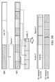
- Figs. 5A and 5B show a schematic diagram illustrating the logic channel prioritization according to the example of Table 1.
- the uplink data to be transmitted is received per Radio Bearer (RB).
- RB1 is configured to carry the VoLTE data, and thus has a higher priority
- RB2 is configured to carry general data (including ACKs of DL TCP, ARQ ACKs, and other data packets), and thus has a lower priority.
- Each RB has a respective bucket size determined in the first place when the RB is established. It should be noted that the important data is prioritized to be placed into the corresponding bucket for each RB. That is, the VoLTE data for RB1 is placed into bucket 1, and the ACKs of DL TCP and ARQ ACKs for RB2 are placed into bucket 2.
- the uplink resource assignments for the second component carrier are first allocated to the uplink data placed in buckets 1 and 2.
- the process proceeds to allocate the uplink resource assignments for the first component carrier to the uplink data placed in buckets 1 and 2.
- Figs. 5A and 5B apply the logic channel prioritization to each uplink resource assignment independently, it should be appreciated by those skilled in the art that the logic channel prioritization may be applied to the sum of the capacities of all uplink resource assignments.
- the conventional scheduling based on the priority level of each radio bearer may be used instead.
- the present application realizes enhanced logical channel prioritization by arranging important uplink data to be transmitted using the uplink resource assignment corresponding to the component carrier with a higher service level.
- this improves the transmission performance, especially when the service levels of the multiple component carriers vary greatly from one another.
Landscapes
- Engineering & Computer Science (AREA)
- Signal Processing (AREA)
- Computer Networks & Wireless Communication (AREA)
- Quality & Reliability (AREA)
- Mobile Radio Communication Systems (AREA)
Abstract
Description
- This Application claims priority of
U.S. Provisional Application No. 62/080,635, filed on November 17, 2014 - The application generally relates to logic channel prioritization, and more particularly, to logic channel prioritization for multiple component carriers.
- With growing demand for ubiquitous computing and networking, various cellular technologies have been developed, including the Global System for Mobile communications (GSM) technology, General Packet Radio Service (GPRS) technology, Enhanced Data rates for Global Evolution (EDGE) technology, Wideband Code Division Multiple Access (WCDMA) technology, Code Division Multiple Access 2000 (CDMA2000) technology, Time Division-Synchronous Code Division Multiple Access (TD-SCDMA) technology, Worldwide Interoperability for Microwave Access (WiMAX) technology, Long Term Evolution (LTE) technology, Time- Division LTE (TD-LTE) technology, and LTE-Advanced (LTE-A) technology, etc.
- Using the LTE technology in compliance with the 3GPP TS 36.321, release 9 specification as an example, a User Equipment (UE) supports only a single carrier transmission and reception. An LTE network may assign uplink resources on the signal component carrier for the UE to transmit uplink data, and the UE has to perform a logical channel prioritization procedure to properly allocate the uplink resource assignments for uplink data transmissions on the single component carrier according to the priority levels of each radio bearer and predetermined bucket size.
- In order to meet the demand for higher data rates in wireless communications, support for wider transmission bandwidths is required, and the so-called Carrier Aggregation (CA) technique has been proposed to allow for the expansion of effective bandwidths delivered to a User Equipment (UE) through concurrent utilization of radio resources across multiple carriers. The CA technique is most useful when it is difficult to derive a contiguous and extra wide bandwidth. Using the CA technique, more than 2 frequency bands may be aggregated to form a larger transmission/reception bandwidth. Each of the aggregated frequency channels is generally referred to as a component carrier, which may be taken as a component of the aggregated bandwidth.
- With the advancement from single-carrier transceiving to multiple-carrier transceiving, a UE may be assigned with uplink resources for each component carrier. Using the LTE-A technology in compliance with the 3GPP TS 36.321, release 10 specification as an example; when the UE is requested to transmit multiple Medium Access Control (MAC) Packet Data Units (PDUs) over several component carriers in one Transmission Time Interval (TTI), it may apply the same logical channel prioritization procedure as defined for the single carrier scenario to the uplink resource assignments of each component carrier independently, or to the sum of the uplink resource assignments of all component carriers.
- In an aspect of the application, a mobile communication device comprising a wireless transceiver and a controller is provided. The wireless transceiver is configured to perform wireless transmission and reception to and from a service network via a plurality of component carriers. The controller is configured to determine a plurality of service levels, each corresponding to a respective one of the component carriers, and allocate uplink resource assignments for uplink data transmissions according to the service levels and traffic type of the uplink data.
- In another aspect of the application, a method for logic channel prioritization, which is executed by a mobile communication device wirelessly communicating with a service network via a plurality of component carriers, is provided. The method comprises the steps of: determining a plurality of service levels, each corresponding to a respective one of the component carriers; and allocating uplink resource assignments for uplink data transmissions according to the service levels and traffic type of the uplink data.
- Other aspects and features of the present application will become apparent to those with ordinarily skill in the art upon review of the following descriptions of specific embodiments of the mobile communication devices and the methods for logic channel prioritization.
- The application can be more fully understood by reading the subsequent detailed description and examples with references made to the accompanying drawings, wherein:
-
Fig. 1 is a block diagram of a wireless communication environment according to an embodiment of the invention; -
Fig. 2 is a block diagram illustrating themobile communication device 110 according to an embodiment of the application; -
Fig. 3 is a schematic diagram illustrating an exemplary frequency spectrum of the LTE-A technology; -
Fig. 4 is a flow chart illustrating the method for logic channel prioritization according to an embodiment of the application; and -
Figs. 5A and5B show a schematic diagram illustrating the logic channel prioritization according to the example of Table 1. - The following description is made for the purpose of illustrating the general principles of the application and should not be taken in a limiting sense. It should be understood that the embodiments may be realized in software, hardware, firmware, or any combination thereof. The 3GPP specifications are used to teach the spirit of the application, and the application is not limited thereto.
-
Fig. 1 is a block diagram of a wireless communication environment according to an embodiment of the invention. Thewireless communication environment 100 comprises amobile communication device 110 and aservice network 120, wherein themobile communication device 110 supports multiple component carriers and is wirelessly connected to theservice network 120 for obtaining mobile services. Themobile communication device 110 may be a feature phone, a smartphone, a panel Personal Computer (PC), a laptop computer, or any computing device supporting the wireless technology utilized by theservice network 120. Theservice network 120 may be a cellular network supporting multiple component carriers, such as an LTE-A network. - Specifically, the
service network 120 comprises anaccess network 121 and acore network 122, wherein theaccess network 121 is responsible for processing radio signals, terminating radio protocols, and connecting themobile communication device 110 with thecore network 122, while thecore network 122 is responsible for performing mobility management, network-side authentication, and interfaces with public/external networks (e.g., the Internet). Each of theaccess network 121 and thecore network 122 may comprise one or more network nodes for carrying out said functions. For example, if theservice network 120 is an LTE-A network, theaccess network 121 may be an Evolved-UTRAN (E-UTRAN) which includes at least an evolved NB (eNB) (e.g., a home eNB, macro BS, or pico BS), and thecore network 122 may be an Evolved Packet Core (EPC) which includes a Home Subscriber Server (HSS), Mobility Management Entity (MME), Serving Gateway (S-GW), and Packet Data Network Gateway (PDN-GW or P-GW). -
Fig. 2 is a block diagram illustrating themobile communication device 110 according to an embodiment of the application. Themobile communication device 110 comprises awireless transceiver 10, acontroller 20, astorage device 30, adisplay device 40, and aninput device 50. Thewireless transceiver 10 is configured to perform wireless transmission and reception to and from theservice networks 120 and 130. Thewireless transceiver 10 comprises a Radio Frequency (RF)device 11, abaseband processing device 12, and anantenna 13. Thebaseband processing device 12 is configured to perform baseband signal processing and control the communications between subscriber identity card(s) (not shown) and theRF device 11. Thebaseband processing device 12 may contain multiple hardware components to perform the baseband signal processing, including Analog-to-Digital Conversion (ADC)/Digital-to-Analog Conversion (DAC), gain adjusting, modulation/demodulation, encoding/decoding, and so on. TheRF device 11 may receive RF wireless signals via theantenna 13, convert the received RF wireless signals to baseband signals, which are processed by thebaseband processing device 12, or receive baseband signals from thebaseband processing device 12 and convert the received baseband signals to RF wireless signals, which are later transmitted via theantenna 13. TheRF device 11 may also contain multiple hardware devices to perform radio frequency conversion. For example, theRF device 10 may comprise a mixer to multiply the baseband signals with a carrier oscillated in the radio frequency of the supported cellular technologies, wherein the radio frequency may be 900MHz, 2100MHz, or 2.6GHz utilized in LTE-A technology, or another radio frequency, depending on the cellular technology in use. - The
controller 20 may be a general-purpose processor, a Micro Control Unit (MCU), an application processor, a Digital Signal Processor (DSP), or the like, for controlling thewireless transceiver 10 for wireless communications with theservice networks 120 and 130, storing and retrieving data to and from thestorage device 30, sending a series of frame data (e.g. representing text messages, graphics, images, etc.) to thedisplay device 40, receiving signals from theinput device 50. In particular, thecontroller 20 coordinates the aforementioned operations of thewireless transceiver 10, thestorage device 30, thedisplay device 40, and theinput device 50 for performing the method for logic channel prioritization. - In another embodiment, the
controller 20 may be incorporated into thebaseband processing device 12, serving as a baseband processor. - The
storage device 30 may be a memory, such as a FLASH memory or a Non-volatile Random Access Memory (NVRAM), or a magnetic storage device, such as a hard disk or a magnetic tape, or an optical disc, or any combination thereof for storing cell information of legacy networks (e.g., the service network 130) and instructions and/or program code of applications and/or communication protocols. - The
display device 40 may be a Liquid-Crystal Display (LCD), Light-Emitting Diode (LED) display, or Electronic Paper Display (EPD), etc., for providing a display function. Alternatively, thedisplay device 30 may further comprise one or more touch sensors disposed thereon or thereunder for sensing touches, contacts, or approximations of objects, such as fingers or styluses. - The
input device 50 may comprise one or more buttons, a keyboard, a mouse, a touch pad, a video camera, a microphone, and/or a speaker, etc., serving as the Man-Machine Interface (MMI) for interaction with users. - It should be understood that the components described in the embodiment of
Fig. 2 are for illustrative purposes only and are not intended to limit the scope of the application. -
Fig. 3 is a schematic diagram illustrating an exemplary frequency spectrum of the LTE-A technology. As shown inFig. 3 , five carriers are shown (denoted withreference numerals - In the example of
Fig. 3 , when multiple component carriers are configured, the minimum uplink bandwidth will be 40 MHz if two of the 5 component carriers with 20 MHz are aggregated, and the maximum uplink bandwidth will be 100 MHz if all of the 5 component carriers with 20 MHz are aggregated. As will be appreciated by those skilled in the art, dependent on the deployment scenario, carrier aggregation may occur with component carriers located in the same frequency band or certain carriers may be located in non-adjacent or non-contiguous frequency bands. For example, one carrier may be located in the 2.6 GHz frequency band and a second non-adjacent aggregated carrier may be located at the 900 MHz frequency band. -
Fig. 4 is a flow chart illustrating the method for logic channel prioritization according to an embodiment of the application. In this embodiment, the method for logic channel prioritization is executed by a mobile communication device, e.g., themobile communication device 110, which is configured to perform wireless transceiving with a service network via a plurality of component carriers. To begin, the mobile communication device receives a plurality of uplink resource assignments for uplink data transmissions on the component carriers within a TTI (step S410). That is, each uplink resource assignment is dedicated for uplink data transmissions on a respective component carrier. Next, the mobile communication device determines a plurality of service levels, each corresponding to a respective one of the component carriers (step S420). - Specifically, each service level is determined according to a signal quality indicator of the corresponding component carrier, channel feedbacks of the corresponding component carrier, and/or a configuration of the uplink resource assignments of the corresponding component carrier.
- The signal quality indicator may be a Received Signal Strength Indication (RSSI), Signal to Noise Ratio (SNR), Adjacent Channel Interference (ACI), Packet Error Rate (PER), Bit Error Rate (BER), BLock Error Rate (BLER), Channel Quality Indicator (CQI), or a Rank Indicator (RI). For example, the greater value of the RSSI, SNR, CQI, or RI, the higher service level of the corresponding component carrier. Likewise, the smaller value of the ACI, PER, BER, BLER, the higher service level of the corresponding component carrier. It should be understood that the signal quality indicators described herein are for illustrative purposes only and are not intended to limit the scope of the application.
- The channel feedbacks may be an Automatic Repeat reQuest (ARQ) Acknowledgement (ACK) or Non-ACK (NACK), or a Hybrid ARQ (HARQ) ACK or NACK. For example, the ratio of the number of received HARQ ACK/NACK or ACQ ACK/NACK may be used as a factor for determining the service level of the corresponding component carrier, and the greater the ratio of the channel feedbacks, the higher service level of the corresponding component carrier.
- The configuration of the uplink resource assignments may include a resource block size, an operating frequency, or a transmission power/power headroom configured for the uplink resource assignments of the corresponding component carrier. For example, the component carrier operating on 700 MHz may be expected to have a better service level than the component carrier operating on 2.5 GHz, due to the fact the 700 MHz signals have a better ability to penetrate walls while the 2.5 GHz signals may be more likely to be interfered with by the close-band 2.4 GHz operating frequency of the Wireless Fidelity (WiFi) technology. Alternatively, a component carrier configured to use a greater transmission power or power headroom may be expected to have a better service level, or a component carrier configured with a greater resource block size may be expected to have a better service level.
- An exemplary table for determining the service level for each component carrier is shown below in Table 1.
Table 1. Index of component carrier RSSI HARQ ACK/NACK Operating frequency Service level CC#1 -45 dBm 10/4 2.5 GHz 2 CC#2 -40 dBm 10/2 700 MHz 1 - In this example, two component carriers are configured for uplink data transmissions, and the signal quality indicator is RSSI, the channel feedbacks are HARQ ACK and NACK, and the configuration of the uplink resource assignment is operating frequency. The service levels of the component carriers may be determined based on any combination of the RSSI, the ratio of HARQ ACK/NACK, and the configuration of the uplink resource assignment. For example, the RSSI is used as the first reference, and the ratio of HARQ ACK/NACK is used as the second reference if both the component carriers have the same RSSI, and the configuration of the uplink resource assignment is used as the third reference if both the component carriers have the same ratio of HARQ ACK/NACK. Alternatively, the RSSI, the ratio of HARQ ACK/NACK, and the configuration of the uplink resource assignment may be given different weights, and each value of the RSSI, the ratio of HARQ ACK/NACK, and the configuration of the uplink resource assignment is multiplied by the respective weight to generate a weighted sum for determining the service levels.
- Subsequent to step S420, the mobile communication device generates a list of the component carriers in a descending order of the service levels (step S430), and allocates the uplink resource assignments for uplink data transmissions according to the list and the traffic type of the uplink data (step S440). Specifically, the mobile communication device prioritizes the allocation of the uplink resource assignments with the component carriers from the top of the list to important uplink data with the traffic type indicating a Non Access Stratum (NAS) or Radio Resource Control (RRC) message, an Acknowledgements of a Downlink Transmission Control Protocol (TCP) transmission, Voice over Long Term Evolution (VoLTE) or Video over LTE (ViLTE) data, or a channel feedback (e.g., ARQ ACKs).
-
Figs. 5A and5B show a schematic diagram illustrating the logic channel prioritization according to the example of Table 1. As shown inFig. 5A , the uplink data to be transmitted is received per Radio Bearer (RB). Specifically, RB1 is configured to carry the VoLTE data, and thus has a higher priority; while RB2 is configured to carry general data (including ACKs of DL TCP, ARQ ACKs, and other data packets), and thus has a lower priority. Each RB has a respective bucket size determined in the first place when the RB is established. It should be noted that the important data is prioritized to be placed into the corresponding bucket for each RB. That is, the VoLTE data for RB1 is placed intobucket 1, and the ACKs of DL TCP and ARQ ACKs for RB2 are placed intobucket 2. - As the service level of the second component carrier (denoted as CC#2) is higher than that of the first component carrier (denoted as CC#1), the uplink resource assignments for the second component carrier are first allocated to the uplink data placed in
buckets - After that, as shown in
Fig. 5B , the subsequent VoLTE data for RB1 is placed intobucket 1, and the other data packets for RB2 are placed intobucket 2. Since the uplink resource assignments for the second component carrier have been allocated, the process proceeds to allocate the uplink resource assignments for the first component carrier to the uplink data placed inbuckets - Although the examples shown in
Figs. 5A and5B apply the logic channel prioritization to each uplink resource assignment independently, it should be appreciated by those skilled in the art that the logic channel prioritization may be applied to the sum of the capacities of all uplink resource assignments. - It should be noted that, after prioritizing the important data to be transmitted using the uplink resource assignment corresponding to the component carrier with a higher service level, the conventional scheduling based on the priority level of each radio bearer may be used instead.
- In view of the forgoing embodiment of
Figs. 4 ,5A , and5B , it will be appreciated that the present application realizes enhanced logical channel prioritization by arranging important uplink data to be transmitted using the uplink resource assignment corresponding to the component carrier with a higher service level. Advantageously, this improves the transmission performance, especially when the service levels of the multiple component carriers vary greatly from one another. - Other detailed descriptions of the logical channel prioritization procedure are omitted herein for brevity since it is beyond the scope of the application, and reference may be made to the 3GPP TS 36.321,
release 10/11/12. - While the application has been described by way of example and in terms of preferred embodiment, it should be understood that the application is not limited thereto. Those who are skilled in this technology can still make various alterations and modifications without departing from the scope and spirit of this application. For example, the method for logical channel prioritization may be applied in any future evolution of the LTE-A technology. Therefore, the scope of the present application shall be defined and protected by the following claims and their equivalents.
Claims (14)
- A mobile communication device (110), comprising:a wireless transceiver (10), configured to perform wireless transmission and reception to and from a service network (120) via a plurality of component carriers; anda controller (20), configured to determine a plurality of service levels, each corresponding to a respective one of the component carriers, and allocate uplink resource assignments for uplink data transmissions according to the service levels and traffic type of the uplink data.
- The mobile communication device of claim 1, wherein the controller is further configured to generate a list of the component carriers in a descending order of the service levels, and prioritize the allocation of the uplink resource assignments with the component carriers from the top of the list to the uplink data with the traffic type indicating that the uplink data comprises a Non Access Stratum, NAS, or Radio Resource Control, RRC, message, an Acknowledgement of a Downlink Transmission Control Protocol, TCP, transmission, Voice over Long Term Evolution, VoLTE, or Video over LTE, ViLTE, data, or a channel feedback.
- The mobile communication device of claim 1 or 2, wherein each of the service levels is determined according to any combination of the following:a signal quality indicator of the corresponding component carrier;channel feedbacks of the corresponding component carrier; anda configuration of the uplink resource assignments of the corresponding component carrier.
- The mobile communication device of claim 3, wherein the signal quality indicator is a Received Signal Strength Indication, RSSI, Signal to Noise Ratio, SNR, Adjacent Channel Interference, ACI, Packet Error Rate, PER, Bit Error Rate, BER, BLock Error Rate, BLER, Channel Quality Indicator, CQI, or a Rank Indicator, RI.
- The mobile communication device of claim 3 or 4, wherein the channel feedback is an Automatic Repeat request, ARQ, Acknowledgement, ACK, or Non-ACK, NACK, or a Hybrid ARQ,(HARQ ACK or NACK.
- The mobile communication device of any of the claims 3 to 5, wherein the configuration of the uplink resource assignments comprises a resource block size, an operating frequency, a transmission power, or a power headroom configured for the uplink resource assignments of the corresponding component carrier.
- The mobile communication device of any of the claims 1 to 6, wherein the controller is further configured to allocate the uplink resource assignments for the uplink data transmissions according to priority levels of a plurality of radio bearers which the uplink data is associated with.
- A method for logic channel prioritization, which is executed by a mobile communication device wirelessly communicating with a service network via a plurality of component carriers, the method comprising:determining a plurality of service levels, each corresponding to a respective one of the component carriers; andallocating uplink resource assignments for uplink data transmissions according to the service levels and traffic type of the uplink data.
- The method of claim 8, further comprising:generating a list of the component carriers in a descending order of the service levels; andprioritizing the allocation of the uplink resource assignments with the component carriers from the top of the list to the uplink data with the traffic type indicating that the uplink data comprises a Non Access Stratum, NAS, or Radio Resource Control, RRC, message, an Acknowledgement of a Downlink Transmission Control Protocol, TCP, transmission, Voice over Long Term Evolution, VoLTE, or Video over LTE, ViLTE, data, or a channel feedback.
- The method of claim 8 or 9, wherein each of the service levels is determined according to any combination of the following:a signal quality indicator of the corresponding component carrier;channel feedbacks of the corresponding component carrier; anda configuration of the uplink resource assignments of the corresponding component carrier.
- The method of claim 10, wherein the signal quality indicator is a Received Signal Strength Indication, RSSI, Signal to Noise Ratio, SNR, Adjacent Channel Interference, ACI, Packet Error Rate, PER, Bit Error Rate ,BER, BLock Error Rate ,BLER, Channel Quality Indicator ,CQI, or a Rank Indicator, RI.
- The method of claim 10, wherein the channel feedback is an Automatic Repeat reQuest, ARQ, Acknowledgement, ACK, or Non-ACK, NACK, or a Hybrid ARQ, HARQ, ACK or NACK.
- The method of claim 10, 11 or 12, wherein the configuration of the uplink resource assignments comprises a resource block size, an operating frequency, a transmission power, or a power headroom configured for the uplink resource assignments of the corresponding component carrier.
- The method of any of the claims 8 to 13, further comprising:allocating the uplink resource assignments for the uplink data transmissions according to priority levels of a plurality of radio bearers which the uplink data is associated with.
Applications Claiming Priority (2)
| Application Number | Priority Date | Filing Date | Title |
|---|---|---|---|
| US201462080635P | 2014-11-17 | 2014-11-17 | |
| US14/940,647 US20160143025A1 (en) | 2014-11-17 | 2015-11-13 | Apparatuses and methods for logic channel prioritization |
Publications (1)
| Publication Number | Publication Date |
|---|---|
| EP3021513A1 true EP3021513A1 (en) | 2016-05-18 |
Family
ID=54545031
Family Applications (1)
| Application Number | Title | Priority Date | Filing Date |
|---|---|---|---|
| EP15194911.2A Withdrawn EP3021513A1 (en) | 2014-11-17 | 2015-11-17 | Apparatuses and methods for logic channel prioritization |
Country Status (3)
| Country | Link |
|---|---|
| US (1) | US20160143025A1 (en) |
| EP (1) | EP3021513A1 (en) |
| CN (1) | CN105610558A (en) |
Cited By (3)
| Publication number | Priority date | Publication date | Assignee | Title |
|---|---|---|---|---|
| CN109906647A (en) * | 2016-12-16 | 2019-06-18 | 富士通株式会社 | Data multiplexing device, method and communication system |
| US11503553B1 (en) | 2021-06-24 | 2022-11-15 | T-Mobile Usa, Inc. | Allocation of resource blocks based on traffic priority |
| US11558827B1 (en) | 2021-06-24 | 2023-01-17 | T-Mobile Usa, Inc. | Maximum power reduction based on power headroom |
Families Citing this family (7)
| Publication number | Priority date | Publication date | Assignee | Title |
|---|---|---|---|---|
| US10660072B2 (en) * | 2015-03-18 | 2020-05-19 | Apple Inc. | Terminal device and mobile radio communication by terminal device |
| WO2017164668A1 (en) * | 2016-03-24 | 2017-09-28 | Lg Electronics Inc. | Method for transmitting data in a communication system and device therefor |
| EP3506540A4 (en) * | 2016-09-28 | 2019-09-18 | Huawei Technologies Co., Ltd. | Data transmission method, network device and terminal device |
| CN108207032A (en) * | 2016-12-16 | 2018-06-26 | 华硕电脑股份有限公司 | Method and apparatus for handling uplink resource collision in wireless communication system |
| WO2018119749A1 (en) * | 2016-12-28 | 2018-07-05 | Mediatek Singapore Pte. Ltd. | Methods to support ul transmission on multiple numerologies in nr system |
| CN107223359B (en) | 2017-04-28 | 2021-08-31 | 北京小米移动软件有限公司 | Method, apparatus, user equipment and base station for channel carrier configuration |
| EP3541017B1 (en) * | 2018-03-13 | 2021-11-10 | Nokia Solutions and Networks Oy | Method and apparatus for monitoring a telecommunication network |
Citations (3)
| Publication number | Priority date | Publication date | Assignee | Title |
|---|---|---|---|---|
| US20100281486A1 (en) * | 2009-05-04 | 2010-11-04 | HT mMobile Inc. | Enhanced scheduling, priority handling and multiplexing method and system |
| EP2398181A2 (en) * | 2010-06-18 | 2011-12-21 | Research In Motion Limited | System and method for uplink control information transmission in carrier aggregation |
| EP2645800A1 (en) * | 2009-04-23 | 2013-10-02 | Panasonic Corporation | Logical Channel Prioritization Procedure for Generating Multiple Uplink Transport Blocks |
Family Cites Families (7)
| Publication number | Priority date | Publication date | Assignee | Title |
|---|---|---|---|---|
| KR101257316B1 (en) * | 2007-01-19 | 2013-04-24 | 가부시키가이샤 엔티티 도코모 | Base station device and communication control method |
| US8630270B2 (en) * | 2008-06-30 | 2014-01-14 | Interdigital Patent Holdings, Inc. | MAC multiplexing for uplink MIMO |
| CN101902817B (en) * | 2009-05-26 | 2015-07-22 | 中兴通讯股份有限公司 | Uplink radio resource dispatching method and device for wireless communication system |
| CN101657018B (en) * | 2009-08-18 | 2015-01-28 | 中兴通讯股份有限公司 | Indicating method and base station, decoding method and terminal for wireless channel resource allocation |
| CN101702644B (en) * | 2009-11-02 | 2014-08-13 | 中兴通讯股份有限公司 | A transmission method and device for a physical hybrid retransmission indication channel |
| US8638815B2 (en) * | 2010-01-08 | 2014-01-28 | Blackberry Limited | Method and apparatus for logical channel prioritization for uplink carrier aggregation |
| US10110355B2 (en) * | 2014-03-10 | 2018-10-23 | Apple Inc. | Uplink transmission on unlicensed radio frequency band component carriers |
-
2015
- 2015-11-13 US US14/940,647 patent/US20160143025A1/en not_active Abandoned
- 2015-11-17 CN CN201510791138.2A patent/CN105610558A/en not_active Withdrawn
- 2015-11-17 EP EP15194911.2A patent/EP3021513A1/en not_active Withdrawn
Patent Citations (3)
| Publication number | Priority date | Publication date | Assignee | Title |
|---|---|---|---|---|
| EP2645800A1 (en) * | 2009-04-23 | 2013-10-02 | Panasonic Corporation | Logical Channel Prioritization Procedure for Generating Multiple Uplink Transport Blocks |
| US20100281486A1 (en) * | 2009-05-04 | 2010-11-04 | HT mMobile Inc. | Enhanced scheduling, priority handling and multiplexing method and system |
| EP2398181A2 (en) * | 2010-06-18 | 2011-12-21 | Research In Motion Limited | System and method for uplink control information transmission in carrier aggregation |
Cited By (6)
| Publication number | Priority date | Publication date | Assignee | Title |
|---|---|---|---|---|
| CN109906647A (en) * | 2016-12-16 | 2019-06-18 | 富士通株式会社 | Data multiplexing device, method and communication system |
| CN109906647B (en) * | 2016-12-16 | 2023-05-05 | 富士通株式会社 | Data multiplexing device, method and communication system |
| US11503553B1 (en) | 2021-06-24 | 2022-11-15 | T-Mobile Usa, Inc. | Allocation of resource blocks based on traffic priority |
| US11558827B1 (en) | 2021-06-24 | 2023-01-17 | T-Mobile Usa, Inc. | Maximum power reduction based on power headroom |
| US12356341B2 (en) | 2021-06-24 | 2025-07-08 | T-Mobile Usa, Inc. | Maximum power reduction based on traffic priority |
| US12628094B2 (en) | 2021-06-24 | 2026-05-12 | T-Mobile Usa, Inc. | Maximum power reduction based on power headroom |
Also Published As
| Publication number | Publication date |
|---|---|
| US20160143025A1 (en) | 2016-05-19 |
| CN105610558A (en) | 2016-05-25 |
Similar Documents
| Publication | Publication Date | Title |
|---|---|---|
| US20160143025A1 (en) | Apparatuses and methods for logic channel prioritization | |
| CN111213416B (en) | Dynamic management of uplink control signaling resources in a wireless network | |
| CN109151833B (en) | Method and apparatus for transmitting control information | |
| EP3549376B1 (en) | Transmission with multiple numerologies in new radio system | |
| CN111630906B (en) | Transmit power control command handling across multiple downlink control information | |
| US9532356B2 (en) | Component carrier configuration | |
| US9241327B2 (en) | LTE enhancements for small packet transmissions | |
| CN103168441B (en) | Systems and methods for uplink control information transmission in carrier aggregation | |
| JP5709334B2 (en) | Resource allocation in PUCCH format 1b for channel selection in LTE-ATDD system | |
| KR101425959B1 (en) | Assignment of component carriers | |
| AU2021204172B2 (en) | Allocation of communication resources for control signals in the uplink | |
| US9913254B2 (en) | Method and apparatus for indicating subframes associated with a hybrid automatic repeat request feedback | |
| CN102355325B (en) | PUCCH resource mapping method and apparatus thereof | |
| CN102823307B (en) | power headroom reporting | |
| EP2490496B1 (en) | Resource configuration method, equipment and system for uplink control channel | |
| JP2013526216A (en) | System and method for uplink control information transmission in carrier aggregation | |
| AU2017308583A1 (en) | Data channel-referenced resource allocation for a control channel | |
| US9693344B2 (en) | Allocation of communication resources | |
| EP2834936B1 (en) | Method and apparatus for signaling reference signals to a ue in an lte system | |
| CN107710848A (en) | Data transmission method, device and system | |
| US9338786B2 (en) | Reference signal transmitting method, mobile terminal apparatus and radio base station apparatus | |
| WO2024059984A1 (en) | Method and apparatus for determining transport block size, and device and storage medium | |
| EP2635081B1 (en) | Allocation of communication resources | |
| EP4668956A1 (en) | Transport block size determining method and apparatus, device, and storage medium | |
| HK40033338B (en) | Dynamic management of uplink control signaling resources in wireless network |
Legal Events
| Date | Code | Title | Description |
|---|---|---|---|
| PUAI | Public reference made under article 153(3) epc to a published international application that has entered the european phase |
Free format text: ORIGINAL CODE: 0009012 |
|
| AK | Designated contracting states |
Kind code of ref document: A1 Designated state(s): AL AT BE BG CH CY CZ DE DK EE ES FI FR GB GR HR HU IE IS IT LI LT LU LV MC MK MT NL NO PL PT RO RS SE SI SK SM TR |
|
| AX | Request for extension of the european patent |
Extension state: BA ME |
|
| STAA | Information on the status of an ep patent application or granted ep patent |
Free format text: STATUS: REQUEST FOR EXAMINATION WAS MADE |
|
| 17P | Request for examination filed |
Effective date: 20161117 |
|
| RBV | Designated contracting states (corrected) |
Designated state(s): AL AT BE BG CH CY CZ DE DK EE ES FI FR GB GR HR HU IE IS IT LI LT LU LV MC MK MT NL NO PL PT RO RS SE SI SK SM TR |
|
| STAA | Information on the status of an ep patent application or granted ep patent |
Free format text: STATUS: EXAMINATION IS IN PROGRESS |
|
| 17Q | First examination report despatched |
Effective date: 20170407 |
|
| STAA | Information on the status of an ep patent application or granted ep patent |
Free format text: STATUS: THE APPLICATION IS DEEMED TO BE WITHDRAWN |
|
| 18D | Application deemed to be withdrawn |
Effective date: 20170818 |