EP3021392A1 - Fuel cell unit cell - Google Patents
Fuel cell unit cell Download PDFInfo
- Publication number
- EP3021392A1 EP3021392A1 EP14822988.3A EP14822988A EP3021392A1 EP 3021392 A1 EP3021392 A1 EP 3021392A1 EP 14822988 A EP14822988 A EP 14822988A EP 3021392 A1 EP3021392 A1 EP 3021392A1
- Authority
- EP
- European Patent Office
- Prior art keywords
- gas diffusion
- diffusion layer
- diffusion layers
- holes
- layers
- Prior art date
- Legal status (The legal status is an assumption and is not a legal conclusion. Google has not performed a legal analysis and makes no representation as to the accuracy of the status listed.)
- Granted
Links
Images


Classifications
-
- H—ELECTRICITY
- H01—ELECTRIC ELEMENTS
- H01M—PROCESSES OR MEANS, e.g. BATTERIES, FOR THE DIRECT CONVERSION OF CHEMICAL ENERGY INTO ELECTRICAL ENERGY
- H01M8/00—Fuel cells; Manufacture thereof
- H01M8/10—Fuel cells with solid electrolytes
- H01M8/1004—Fuel cells with solid electrolytes characterised by membrane-electrode assemblies [MEA]
-
- H—ELECTRICITY
- H01—ELECTRIC ELEMENTS
- H01M—PROCESSES OR MEANS, e.g. BATTERIES, FOR THE DIRECT CONVERSION OF CHEMICAL ENERGY INTO ELECTRICAL ENERGY
- H01M4/00—Electrodes
- H01M4/86—Inert electrodes with catalytic activity, e.g. for fuel cells
- H01M4/8605—Porous electrodes
-
- H—ELECTRICITY
- H01—ELECTRIC ELEMENTS
- H01M—PROCESSES OR MEANS, e.g. BATTERIES, FOR THE DIRECT CONVERSION OF CHEMICAL ENERGY INTO ELECTRICAL ENERGY
- H01M4/00—Electrodes
- H01M4/86—Inert electrodes with catalytic activity, e.g. for fuel cells
- H01M4/8647—Inert electrodes with catalytic activity, e.g. for fuel cells consisting of more than one material, e.g. consisting of composites
- H01M4/8657—Inert electrodes with catalytic activity, e.g. for fuel cells consisting of more than one material, e.g. consisting of composites layered
-
- H—ELECTRICITY
- H01—ELECTRIC ELEMENTS
- H01M—PROCESSES OR MEANS, e.g. BATTERIES, FOR THE DIRECT CONVERSION OF CHEMICAL ENERGY INTO ELECTRICAL ENERGY
- H01M8/00—Fuel cells; Manufacture thereof
- H01M8/02—Details
- H01M8/0202—Collectors; Separators, e.g. bipolar separators; Interconnectors
- H01M8/0204—Non-porous and characterised by the material
- H01M8/0206—Metals or alloys
-
- H—ELECTRICITY
- H01—ELECTRIC ELEMENTS
- H01M—PROCESSES OR MEANS, e.g. BATTERIES, FOR THE DIRECT CONVERSION OF CHEMICAL ENERGY INTO ELECTRICAL ENERGY
- H01M8/00—Fuel cells; Manufacture thereof
- H01M8/02—Details
- H01M8/0202—Collectors; Separators, e.g. bipolar separators; Interconnectors
- H01M8/023—Porous and characterised by the material
- H01M8/0232—Metals or alloys
-
- H—ELECTRICITY
- H01—ELECTRIC ELEMENTS
- H01M—PROCESSES OR MEANS, e.g. BATTERIES, FOR THE DIRECT CONVERSION OF CHEMICAL ENERGY INTO ELECTRICAL ENERGY
- H01M8/00—Fuel cells; Manufacture thereof
- H01M8/02—Details
- H01M8/0202—Collectors; Separators, e.g. bipolar separators; Interconnectors
- H01M8/023—Porous and characterised by the material
- H01M8/0241—Composites
- H01M8/0245—Composites in the form of layered or coated products
-
- H—ELECTRICITY
- H01—ELECTRIC ELEMENTS
- H01M—PROCESSES OR MEANS, e.g. BATTERIES, FOR THE DIRECT CONVERSION OF CHEMICAL ENERGY INTO ELECTRICAL ENERGY
- H01M8/00—Fuel cells; Manufacture thereof
- H01M8/02—Details
- H01M8/0202—Collectors; Separators, e.g. bipolar separators; Interconnectors
- H01M8/0258—Collectors; Separators, e.g. bipolar separators; Interconnectors characterised by the configuration of channels, e.g. by the flow field of the reactant or coolant
- H01M8/026—Collectors; Separators, e.g. bipolar separators; Interconnectors characterised by the configuration of channels, e.g. by the flow field of the reactant or coolant characterised by grooves, e.g. their pitch or depth
-
- H—ELECTRICITY
- H01—ELECTRIC ELEMENTS
- H01M—PROCESSES OR MEANS, e.g. BATTERIES, FOR THE DIRECT CONVERSION OF CHEMICAL ENERGY INTO ELECTRICAL ENERGY
- H01M8/00—Fuel cells; Manufacture thereof
- H01M8/04—Auxiliary arrangements, e.g. for control of pressure or for circulation of fluids
- H01M8/04082—Arrangements for control of reactant parameters, e.g. pressure or concentration
- H01M8/04089—Arrangements for control of reactant parameters, e.g. pressure or concentration of gaseous reactants
- H01M8/04119—Arrangements for control of reactant parameters, e.g. pressure or concentration of gaseous reactants with simultaneous supply or evacuation of electrolyte; Humidifying or dehumidifying
- H01M8/04156—Arrangements for control of reactant parameters, e.g. pressure or concentration of gaseous reactants with simultaneous supply or evacuation of electrolyte; Humidifying or dehumidifying with product water removal
-
- H—ELECTRICITY
- H01—ELECTRIC ELEMENTS
- H01M—PROCESSES OR MEANS, e.g. BATTERIES, FOR THE DIRECT CONVERSION OF CHEMICAL ENERGY INTO ELECTRICAL ENERGY
- H01M8/00—Fuel cells; Manufacture thereof
- H01M8/04—Auxiliary arrangements, e.g. for control of pressure or for circulation of fluids
- H01M8/04082—Arrangements for control of reactant parameters, e.g. pressure or concentration
- H01M8/04201—Reactant storage and supply, e.g. means for feeding, pipes
-
- H—ELECTRICITY
- H01—ELECTRIC ELEMENTS
- H01M—PROCESSES OR MEANS, e.g. BATTERIES, FOR THE DIRECT CONVERSION OF CHEMICAL ENERGY INTO ELECTRICAL ENERGY
- H01M8/00—Fuel cells; Manufacture thereof
- H01M8/04—Auxiliary arrangements, e.g. for control of pressure or for circulation of fluids
- H01M8/04291—Arrangements for managing water in solid electrolyte fuel cell systems
-
- H—ELECTRICITY
- H01—ELECTRIC ELEMENTS
- H01M—PROCESSES OR MEANS, e.g. BATTERIES, FOR THE DIRECT CONVERSION OF CHEMICAL ENERGY INTO ELECTRICAL ENERGY
- H01M8/00—Fuel cells; Manufacture thereof
- H01M8/10—Fuel cells with solid electrolytes
- H01M8/1007—Fuel cells with solid electrolytes with both reactants being gaseous or vaporised
-
- H—ELECTRICITY
- H01—ELECTRIC ELEMENTS
- H01M—PROCESSES OR MEANS, e.g. BATTERIES, FOR THE DIRECT CONVERSION OF CHEMICAL ENERGY INTO ELECTRICAL ENERGY
- H01M8/00—Fuel cells; Manufacture thereof
- H01M8/10—Fuel cells with solid electrolytes
- H01M2008/1095—Fuel cells with polymeric electrolytes
-
- H—ELECTRICITY
- H01—ELECTRIC ELEMENTS
- H01M—PROCESSES OR MEANS, e.g. BATTERIES, FOR THE DIRECT CONVERSION OF CHEMICAL ENERGY INTO ELECTRICAL ENERGY
- H01M4/00—Electrodes
- H01M4/86—Inert electrodes with catalytic activity, e.g. for fuel cells
- H01M4/88—Processes of manufacture
- H01M4/8878—Treatment steps after deposition of the catalytic active composition or after shaping of the electrode being free-standing body
- H01M4/8896—Pressing, rolling, calendering
-
- H—ELECTRICITY
- H01—ELECTRIC ELEMENTS
- H01M—PROCESSES OR MEANS, e.g. BATTERIES, FOR THE DIRECT CONVERSION OF CHEMICAL ENERGY INTO ELECTRICAL ENERGY
- H01M8/00—Fuel cells; Manufacture thereof
- H01M8/02—Details
- H01M8/0202—Collectors; Separators, e.g. bipolar separators; Interconnectors
- H01M8/023—Porous and characterised by the material
- H01M8/0234—Carbonaceous material
-
- H—ELECTRICITY
- H01—ELECTRIC ELEMENTS
- H01M—PROCESSES OR MEANS, e.g. BATTERIES, FOR THE DIRECT CONVERSION OF CHEMICAL ENERGY INTO ELECTRICAL ENERGY
- H01M8/00—Fuel cells; Manufacture thereof
- H01M8/02—Details
- H01M8/0202—Collectors; Separators, e.g. bipolar separators; Interconnectors
- H01M8/023—Porous and characterised by the material
- H01M8/0239—Organic resins; Organic polymers
-
- H—ELECTRICITY
- H01—ELECTRIC ELEMENTS
- H01M—PROCESSES OR MEANS, e.g. BATTERIES, FOR THE DIRECT CONVERSION OF CHEMICAL ENERGY INTO ELECTRICAL ENERGY
- H01M8/00—Fuel cells; Manufacture thereof
- H01M8/02—Details
- H01M8/0202—Collectors; Separators, e.g. bipolar separators; Interconnectors
- H01M8/023—Porous and characterised by the material
- H01M8/0241—Composites
- H01M8/0243—Composites in the form of mixtures
-
- H—ELECTRICITY
- H01—ELECTRIC ELEMENTS
- H01M—PROCESSES OR MEANS, e.g. BATTERIES, FOR THE DIRECT CONVERSION OF CHEMICAL ENERGY INTO ELECTRICAL ENERGY
- H01M8/00—Fuel cells; Manufacture thereof
- H01M8/02—Details
- H01M8/0271—Sealing or supporting means around electrodes, matrices or membranes
- H01M8/0273—Sealing or supporting means around electrodes, matrices or membranes with sealing or supporting means in the form of a frame
-
- H—ELECTRICITY
- H01—ELECTRIC ELEMENTS
- H01M—PROCESSES OR MEANS, e.g. BATTERIES, FOR THE DIRECT CONVERSION OF CHEMICAL ENERGY INTO ELECTRICAL ENERGY
- H01M8/00—Fuel cells; Manufacture thereof
- H01M8/24—Grouping of fuel cells, e.g. stacking of fuel cells
- H01M8/2457—Grouping of fuel cells, e.g. stacking of fuel cells with both reactants being gaseous or vaporised
-
- H—ELECTRICITY
- H01—ELECTRIC ELEMENTS
- H01M—PROCESSES OR MEANS, e.g. BATTERIES, FOR THE DIRECT CONVERSION OF CHEMICAL ENERGY INTO ELECTRICAL ENERGY
- H01M8/00—Fuel cells; Manufacture thereof
- H01M8/24—Grouping of fuel cells, e.g. stacking of fuel cells
- H01M8/2465—Details of groupings of fuel cells
- H01M8/2483—Details of groupings of fuel cells characterised by internal manifolds
-
- Y—GENERAL TAGGING OF NEW TECHNOLOGICAL DEVELOPMENTS; GENERAL TAGGING OF CROSS-SECTIONAL TECHNOLOGIES SPANNING OVER SEVERAL SECTIONS OF THE IPC; TECHNICAL SUBJECTS COVERED BY FORMER USPC CROSS-REFERENCE ART COLLECTIONS [XRACs] AND DIGESTS
- Y02—TECHNOLOGIES OR APPLICATIONS FOR MITIGATION OR ADAPTATION AGAINST CLIMATE CHANGE
- Y02E—REDUCTION OF GREENHOUSE GAS [GHG] EMISSIONS, RELATED TO ENERGY GENERATION, TRANSMISSION OR DISTRIBUTION
- Y02E60/00—Enabling technologies; Technologies with a potential or indirect contribution to GHG emissions mitigation
- Y02E60/30—Hydrogen technology
- Y02E60/50—Fuel cells
Definitions
- the present invention relates to a fuel cell single cell used for polymer electrolyte fuel cells (PEFC) and the like.
- Patent Document 1 titled "Fuel Cell and Electrode Structure for Fuel Cell”.
- the fuel cell described in Patent Document 1 has an MPL that is composed of a sparse area made of electrically conductive particles with a large particle size and a dense area made of electrically conductive particles with a smaller particle size.
- the upper face of the MPL is in contact with a gas diffusion layer, and the lower face is in contact with a catalyst layer.
- the particles of the dense area are of such a particle size that the saturated vapor pressure in the pores determined by the Kelvin equation is higher than the saturated vapor pressure in an open space. In the fuel cell, this makes the saturated vapor pressure in the sparse area lower than the saturated vapor pressure in the dense area, and condensation of water vapor in the dense area is thereby reduced, which is generated in the catalyst layer.
- the present invention was made in view of the above-described problem with the prior art, and an object thereof is to provide a fuel cell single cell in which an improvement in discharging function of liquid water generated during power generation and an improvement in power generation performance are achieved at the same time.
- the fuel cell single cell of the present invention includes a membrane electrode assembly in which an electrolyte membrane is interposed between a pair of electrode layers, and a pair of separators that forms gas channels between the pair of separators and the membrane electrode assembly.
- the electrode layers of the membrane electrode assembly includes a first gas diffusion layer of a porous material disposed at the side facing the electrolyte membrane and a second gas diffusion layer composed of a metal porous body with arrayed many holes, and a part of the first gas diffusion layer penetrates the second gas diffusion layer through the holes to form protrusions. This configuration serves as a means for solving the problem with the prior art.
- the electrode layers have a fine uneven structure on the surface, which is composed of the protrusions of the first gas diffusion layer and the second gas diffusion layer.
- the fine uneven structure can enhance the surface properties (affnity/repellency to water) of the electrode layers compared to an electrode layer composed of only a first gas diffusion layer. This facilitates discharging liquid water that is generated during power generation. Further, this also improves gas diffusion (oxygen transportation) in the electrode layers, and an improvement in power generation performance can therefore be achieved. That is, an improvement in liquid water discharging function and an improvement in power generating function can be achieved at the same time.
- water repellency can be imparted to the electrode layer surfaces without applying water repellent finish to the second gas diffusion layer, which is constituted by a metal porous body. Therefore, the electrical conductivity of the second gas diffusion layer can be readily ensured, which also improves the power generating function.
- a fuel cell FC of FIG. 1 includes a stack S that is constituted by a stacked plurality of fuel cell single cells (hereinafter referred to as "single cells") having a rectangular plate shape.
- the fuel cell FC also includes an end plate 56 disposed on one end in the stacking direction of the stack S (right end in FIG. 1B ) via a current collector plate 54A and a spacer 55, and an end plate 56B disposed on the other end via a current collector plate 54B.
- the fuel FC further includes fastening plates 57A, 57B disposed on opposite faces of the stack S corresponding to the long sides of the single cells C (upper and lower faces in FIG. 1(B) ), and reinforcing plates 58A, 58B disposed on opposite faces corresponding to the short sides.
- the fastening plates 57A, 57B and the reinforcing plates 58A, 58B are coupled to both of the end plates 56A, 56B by means of bolts B.
- the fuel cell FC has a case-integrated structure as illustrated in FIG. 1(A) , which restrains and presses the stack S in the stacking direction to apply a predetermined contact pressure to the individual single cells C so that the gas scaling property, the electrical conductivity and the like are maintained at a high level.
- each of the single cells C of the above-described fuel cell FC includes a membrane electrode assembly M that includes an electrolyte membrane 1 interposed between a pair of electrode layers 2, 3, and a pair of separators 4, 4 that form gas channels G, G between the separators 4,4 and the membrane electrode assembly M.
- FIG. 2 (A) is a cross sectional view taken along the line A-A in FIG. 2 (B) .
- the membrane electrode assembly M which is a so-called MEA, includes an electrolyte membrane 1 of a solid polymer interposed between the anode and cathode electrode layers 2, 3.
- the membrane electrode assembly M includes a resin frame 5 that is integrally provided in the periphery.
- the electrode layers 2, 3 are described in detail below.
- the separators 4, 4 which arc made of stainless steel for example, have predetermined uneven faces formed by press working in which the faces of one plate oppose the faces of the other plate.
- the separators 4, 4 respectively form the anode and cathode gas channels G, G between the membrane electrode assembly M and the separators 4, 4.
- the frame 5 and separators 4 of the membrane electrode assembly M have manifold holes H1 to H3 and H4 to H6 for flowing reaction gas and cooling fluid along the respective short sides.
- the reaction gas is anode gas (hydrogen-containing gas) or cathode gas (air), and the cooling fluid is, for example, water.
- the manifold holes H1 to H3, which are arranged along the left short side in the written order from the top in FIG. 2(B) , are configured respectively to supply the anode gas (H1), to supply the cooling fluid (H2) and to discharge the cathode gas (H3). These manifold holes are communicated with corresponding manifold holes in the stacking direction to form respective channels.
- the manifold holes H4 to H6, which are arranged along the right short side in the written order from the top in FIG. 2(B) are configured respectively to supply the cathode gas (H4), to discharge the cooling fluid (H5) and to discharge the anode gas (H6).
- These manifold hotels are communicated with corresponding manifold holes in the stacking direction to form respective channels.
- the positional relationship of the manifold holes H1 to H6 may be partly or fully changed in respect of the type of fluid, supply and discharge or the like.
- Gas sealers 6 are disposed between the edge parts of the separators 4 and the frame 5 and around the manifold holes H1 to H6, which are partly illustrated in FIG. 2 (A) .
- gas scalers 6 are also disposed between the single cells C, i.e. between adjacent separators 4.
- the gas sealers 6 airtightly separate flow areas of the cathode gas, anode gas and cooling fluid from each other in the respective interlayers.
- the gas sealers 6 have openings at suitable locations in the periphery of the manifold holes H1 to H6 so as to allow only a predetermined fluid to flow in the respective interlayers.
- the electrode layers 2, 3 of the membrane electrode assembly M respectively includes catalyst layers 2A, 3A, first gas diffusion layers 2B, 3B of a porous material, and second gas diffusion layers 2C, 3C of a metal porous body, which are arranged in the written order from the electrolyte membrane 1.
- the first gas diffusion layers 2B, 3B are made of, for example, a carbon material and have at least a water-repellant surface.
- the first gas diffusion layers 2B, 3B are constituted by a binder-hardened random fiber laminate with water repellent finish by PTFE or the like or are constituted by an aggregate of carbon black or the like sintered with a binder such as PTFE.
- the second gas diffusion layer 2C, 3C are constituted by a metal porous body that is ditterent from the porous material of the first gas diffusion layers, and are electrically conductive.
- the second gas diffusion layers 2C, 3C arc made of at least one metal selected from iron, stainless steel, aluminum, an aluminum alloy, chromium, a chromium alloy, nickel, a nickel alloy, magnesium and a magnesium alloy.
- the second gas diffusion layers 2C, 3C are specifically constituted by a metal mesh, a punching metal, an etching metal, an expanded metal or the like.
- the second gas diffusion layers 2C, 3C are constituted by a metal mesh as illustrated in FIG. 3 .
- the mesh openings serve as holes K.
- they arc constituted by a punching metal, an etched metal, an expanded metal or the like, the holes or openings serve as the holes K.
- the linear parts of the second gas diffusion layers 2C, 3C are also referred to as a solid phase portion
- the mesh openings, which are the holes K are also referred to as a gas phase portion.
- the surfaces of the electrode layers 2, 3 have a fine uneven structure that is composed of the protrusions T of the first gas diffusion layers 2B, 3B and the solid phase portions of the second gas diffusion layers 2C, 3C.
- the single cells C with the above-described configuration generate electric energy by electrochemical reaction.
- the electrode layers 2, 3 have enhanced surface properties (affinity/repellency to water) compared to the surface properties of the first gas diffusion layers 2B, 3B.
- the surfaces of the first gas diffusion layers 2B, 3B are water-repellent, it can further enhance the water repellency of the surface of the electrode layers 2, 3.
- this can facilitate discharging liquid water that is generated during the power generation.
- this can also improve gas diffusion (oxygen transportation) in the electrode layers 2, 3, and an improvement in power generation performance can therefore be achieved. That is, an improvement in liquid water discharging function and an improvement in power generating function can be achieved at the same time.
- the metal porous bodies of the second gas diffusion layers 2C, 3C are hydrophilic compared to the first gas diffusion layers 2B, 3B. Accordingly, in order to discharge liquid water, it seems reasonable to provide water repellent finish to the second gas diffusion layers 2C, 3C that arc located at the outer side of the first gas diffusion layers 2B, 3B. However, such water repellent finish on the second gas diffusion layers 2C, 3C may increase the contact resistance with the separators and thereby decrease the power generation performance.
- the surfaces of the electrode layers 2, 3 have enhanced surface properties due to the fine uneven structure without water repellent finish to the second gas diffusion layers 2C, 3C. Furthermore, the surfaces of the electrode layers 2, 3 are also highly water repellent due to the first gas diffusion layers 2B, 3B. Accordingly, the electrical conductivity of the second gas diffusion layers 2C, 3C can be readily ensured. As a result, in the single cells C. the contact resistance between the second gas diffusion layers 2C, 3C and the separators 4 arc not increased, which contributes to improving the power generating function.
- the water repellent surface of the first gas diffusion layers 2B, 3B further improves discharge of the liquid water.
- water contact angle was measured for the surfaces of the first and second gas diffusion layers 2B, 3B, 2C, 3C and the surface with the fine uneven structure of the electrode layers 2, 3.
- the angle on the surface of the first gas diffusion layers 2B, 3B was 144.1°
- the angle on the surface of the second gas diffusion layers 2C, 3C was 83.1°.
- the contact angle on the surface of the electrode layers 2, 3 according to this embodiment was 160° (calculated value). That is, the fine uneven structure of the electrode layers 2, 3 allows water to form droplets on the protrusions T so as not to contact with the solid phase portion of the second gas diffusion layers 2C, 3C. It was demonstrated that high water repellency is thus obtained.
- FIG. 4 illustrates a second embodiment of the present invention.
- the same reference signs are denoted to the same components as those of the first embodiment, and the detailed description thereof are omitted.
- the single cell C in the figure has the same basic configuration as the first embodiment although the separators 4 are not shown.
- the single cell C is configured such that the height H of a protrusion T is greater than a half of the width W (W/2) of a solid phase portion around a hole K, i.e. H ⁇ W/2.
- the width W of the solid phase portion corresponds to the width of the linear parts of the mesh.
- the surface of the electrode layers 2, 3 have enhanced surface properties due to the fine uneven structure and are also highly water repellent due to the first gas diffusion layers 2B, 3B. Therefore, an improvement in liquid water discharging function and an improvement in power generating function can be achieved at the same time. Further, in the single cells C, since the height H of the protrusions T is greater than a half of the width W of the solid phase portion around the holes K, the single cells C exhibit high water repellency against water droplets that have a diameter equal to or greater than the width W of the solid phase portion. Therefore, a further improvement in liquid water discharging function is achieved.
- the single cell of FIG. 5 is configured such that the sum ((Va+Vb) ⁇ (1- ⁇ 1)) of the actual volume (Va ⁇ (1- ⁇ 1)) of the first gas diffusion layers 2B, 3B in a protrusion T and the actual volume (Vb ⁇ (1- ⁇ 1)) of the first gas diffusion layers 2B, 3B in a hole K is equal to or less than the volume Vb of the hole K, i.e. (Va+Vb)x(1- ⁇ 1) ⁇ Vb.
- the actual volume of the first gas diffusion layers 2B, 3B refers to the volume of only the solid phase portion (excluding the gas phase portion) of the first gas diffusion layers 2B, 3B, which is constituted by a porous material.
- Va is the total volume of a protrusion T illustrated by the dashed line in FIG. 5 (B)
- Vb is the total volume of the first gas diffusion layers 2B, 3B in a hole K illustrated by the dashed line in FIG. 5 (B) , which is equal to the volume of the hole K.
- the actual volume of the first gas diffusion layer 2B, 3B in a protrusion T or a hole K is expressed by the total volume Va of the protrusion T, the volume Vb of the hole K and the porosity ⁇ 1 of the first gas diffusion layers 2B, 3B.
- the surface of the electrode layers 2, 3 have enhanced surface properties due to the fine uneven structure and are also highly water repellent due to the first gas diffusion layers 2B, 3B. Therefore, an improvement in liquid water discharging function and an improvement in power generating function can be achieved at the same time.
- the single cells C are configured such that when the membrane electrode assembly M is joined to the separators 4, some af the protrusions T are squashed by the separators 4 as illustrated in the lower part of FIG. 5 (A) .
- the single cell C is configured such that the sum of the actual volume of the first gas diffusion layers 2B, 3B in a protrusion T and the actual volume of the first gas diffusion layers 2B, 3B in a hole K is equal to or less than the volume of the hole K, the first gas diffusion layers 2B, 3B in the hole K have a room (pores) for accommodating the protrusion T.
- the separators 4 squash some protrusions T as illustrated in the figure to come in contact with the second gas diffusion layers 2C, 3C, which are constituted by a metal porous body, and the electrical contact resistance between them are thus reduced. Therefore, the power generation performance can be further improved.
- the single cell C is configured such that the sum ((Va+Vb) ⁇ (1- ⁇ 1)) of the actual volume (Va ⁇ (1- ⁇ 1)) of the first gas diffusion layers 2B, 3B in a protrusion T and the actual volume (Vb ⁇ (1- ⁇ 1)) of the first gas diffusion layers 2B, 3B in a hole K is equal to or less than the volume Vb of the hole K, i.e. (Va+Vb) ⁇ (1- ⁇ 1) ⁇ Vb.
- the sum ((Va+Vb) ⁇ (1- ⁇ 1)) of the actual volume of the first gas diffusion layer 2B, 3B in a protrusion T and the actual volume of the first gas diffusion layer 2B, 3B in a hole K is further selected based on porosity ⁇ 2, which is the porosity of the first gas diffusion layers 2B, 3B after the protrusion T is compressed into the hole K.
- the actual volume (Vb ⁇ (1- ⁇ 2)) of the first gas diffusion layers 2B, 3B after the protrusion T is compressed into the hole K is equal to or greater than the actual volume ((Va+Vb) ⁇ (1- ⁇ 1)) of the first gas diffusion layers 2B, 3B in the protrusion T and the hole K before the compression, i.e. (Va+Vb) ⁇ (1- ⁇ 1) ⁇ Vb ⁇ (1- ⁇ 2).
- the surface of the electrode layers 2, 3 have enhanced surface properties due to the fine uneven structure and are also highly water repellent due to the first gas diffusion layers 2B, 3B. Therefore, an improvement in liquid water discharging function and an improvement in power generating function can be achieved at the same time.
- the single cell C is configured such that when the membrane electrode assembly M is joined to the separators 4, the separators 4 squash the protrusions T as illustrated in the lower part of FIG. 5 (A) to come in contact with the second gas diffusion layers 2C, 3C, the electrical contact resistance between them are thus reduced. Therefore, the power generation performance can be further improved.
- the first gas diffusion layers 2B, 3B in the hole K still have the predetermined porosity ⁇ 2 even after the protrusion T are compressed. Therefore, the gas diffusion can be retained at a high level. In other words, the first gas diffusion layers 2B, 3B have such a porosity that the layers remain porous after the compression.
- first gas diffusion layers 2B, 3B include inner diffusion layers 2B1, 3B1 on the side facing an electrolyte membrane and outer diffusion layers 2B2, 3B2 on the side facing the second gas diffusion layers 2C, 3C.
- the outer diffusion layers 2B2, 3B2 partly penetrate the second gas diffusion layers 2C, 3C through holes K to protrude outward so as to form the fine uneven structure of the surface of the electrode layers 2, 3.
- the membrane electrode assembly M of the single cells can be formed by pressing the first and second gas diffusion layers 2B, 3B, 2C, 3C against each other to plastically deform the first gas diffusion layers 2B, 3B in the thickness direction so that a part of the first gas diffusion layers 2B, 3B is pushed into holes K of the second gas diffusion layers 2C, 3C.
- the porosity is inevitably decreased since the solid phase portions of the second gas diffusion layers 2C, 3C compress the first gas diffusion layers 2B, 3B,
- the first gas diffusion layers 2B, 3B can retain good gas diffusion property, for example, by Joining the outer diffusion layers 2B2, 3B2 of the first gas diffusion layers 2B, 3B with the second gas diffusion layers 2C, 3C to form the protrusions T and thereafter forming the inner diffusion layers 2B2, 3B2.
- the first gas diffusion layers 2B, 3B arc configured such that the strength of the inner diffusion layers 2B1, 3B1 is higher than the strength of the outer diffusion layers 2B2, 3B2.
- the inner diffusion layer 2B1, 3B1 are joined with the outer diffusion layers 2B2, 3B2 to form the first gas diffusion layers 2B, 3B beforehand, and then the first gas diffusion layers 2B, 3B are joined with the second gas diffusion layers 2C, 3C to form the protrusions T.
- the outer diffusion layers 2B2, 3B2 are plastically deformed. Even when the porosity of the outer layers is decreased, the gas diffusion can be retained at a high level due to the inner diffusion layers 2B1, 3B1.
- the surface of the electrode layers 2, 3 have enhanced surface properties due to the fine uneven structure and are also highly water repellent due to the first gas diffusion layers 2B, 3B. Therefore, an improvement in liquid water discharging function and an improvement in power generating function can be achieved at the same time, and the electrode layers 2, 3 can be designed more flexibly.
- the configuration of the fuel cell single cell according to the present invention is not limited to that of the above-described embodiments, and the details of the configuration may be suitably changed without departing from the gist of the present invention.
Landscapes
- Chemical & Material Sciences (AREA)
- Chemical Kinetics & Catalysis (AREA)
- Electrochemistry (AREA)
- General Chemical & Material Sciences (AREA)
- Life Sciences & Earth Sciences (AREA)
- Engineering & Computer Science (AREA)
- Manufacturing & Machinery (AREA)
- Sustainable Development (AREA)
- Sustainable Energy (AREA)
- Composite Materials (AREA)
- Fuel Cell (AREA)
- Inert Electrodes (AREA)
Abstract
Description
- The present invention relates to a fuel cell single cell used for polymer electrolyte fuel cells (PEFC) and the like.
- One of conventional fuel cell single cells is described in
Patent Document 1 titled "Fuel Cell and Electrode Structure for Fuel Cell". The fuel cell described inPatent Document 1 has an MPL that is composed of a sparse area made of electrically conductive particles with a large particle size and a dense area made of electrically conductive particles with a smaller particle size. The upper face of the MPL is in contact with a gas diffusion layer, and the lower face is in contact with a catalyst layer. - In the fuel cell, the particles of the dense area are of such a particle size that the saturated vapor pressure in the pores determined by the Kelvin equation is higher than the saturated vapor pressure in an open space. In the fuel cell, this makes the saturated vapor pressure in the sparse area lower than the saturated vapor pressure in the dense area, and condensation of water vapor in the dense area is thereby reduced, which is generated in the catalyst layer.
- However, in conventional fuel cells including the above-described one, since the dense area has a porosity determined by the Kelvin equation at a nano level, gas diffusion is greatly degraded once liquid water is condensed in the sparse area, which results in the decreased power generation performance. Accordingly, it has been required to solve the problem.
- The present invention was made in view of the above-described problem with the prior art, and an object thereof is to provide a fuel cell single cell in which an improvement in discharging function of liquid water generated during power generation and an improvement in power generation performance are achieved at the same time.
- The fuel cell single cell of the present invention includes a membrane electrode assembly in which an electrolyte membrane is interposed between a pair of electrode layers, and a pair of separators that forms gas channels between the pair of separators and the membrane electrode assembly. In the fuel cell single cell, the electrode layers of the membrane electrode assembly includes a first gas diffusion layer of a porous material disposed at the side facing the electrolyte membrane and a second gas diffusion layer composed of a metal porous body with arrayed many holes, and a part of the first gas diffusion layer penetrates the second gas diffusion layer through the holes to form protrusions. This configuration serves as a means for solving the problem with the prior art.
- In the fuel cell single cell of the present invention, the electrode layers have a fine uneven structure on the surface, which is composed of the protrusions of the first gas diffusion layer and the second gas diffusion layer. The fine uneven structure can enhance the surface properties (affnity/repellency to water) of the electrode layers compared to an electrode layer composed of only a first gas diffusion layer. This facilitates discharging liquid water that is generated during power generation. Further, this also improves gas diffusion (oxygen transportation) in the electrode layers, and an improvement in power generation performance can therefore be achieved. That is, an improvement in liquid water discharging function and an improvement in power generating function can be achieved at the same time.
In the fuel cell single cell, water repellency can be imparted to the electrode layer surfaces without applying water repellent finish to the second gas diffusion layer, which is constituted by a metal porous body. Therefore, the electrical conductivity of the second gas diffusion layer can be readily ensured, which also improves the power generating function. -
-
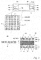
FIG. 1 are (A) perspective view and (B) an exploded perspective view of a fuel cell using fuel cell single cells of the present invention. -
FIG. 2 are (A) a cross sectional view and (B) a plan view of a fuel cell single cell ofFIG. 1 . -
FIG. 3 are (A) a plan view of a fuel cell single cell according to a first embodiment and an enlargement thereof, (B) a cross sectional view of a second gas diffusion layer, and (C) a cross sectional view of the main part of the single cell. -
FIG. 4 are (A) a cross sectional view and (B) an enlarged cross sectional view of the main part of a fuel cell single cell according to a second embodiment. -
FIG. 5 are (A) a cross sectional view and (B) an enlarged cross sectional view of the main part of a fuel cell single cell according to a third and fourth embodiments. -
FIG. 6 are (A) a cross sectional view and (B) an enlarged cross sectional view of the main part of a fuel cell single cell according to a fifth embodiment. - A fuel cell FC of
FIG. 1 includes a stack S that is constituted by a stacked plurality of fuel cell single cells (hereinafter referred to as "single cells") having a rectangular plate shape. The fuel cell FC also includes an end plate 56 disposed on one end in the stacking direction of the stack S (right end inFIG. 1B ) via acurrent collector plate 54A and a spacer 55, and anend plate 56B disposed on the other end via acurrent collector plate 54B. The fuel FC further includesfastening plates FIG. 1(B) ), and reinforcingplates - In the fuel cell FC, the
fastening plates reinforcing plates end plates 56A, 56B by means of bolts B. As described above, the fuel cell FC has a case-integrated structure as illustrated inFIG. 1(A) , which restrains and presses the stack S in the stacking direction to apply a predetermined contact pressure to the individual single cells C so that the gas scaling property, the electrical conductivity and the like are maintained at a high level. - As illustrated in
FIG. 2 , each of the single cells C of the above-described fuel cell FC includes a membrane electrode assembly M that includes anelectrolyte membrane 1 interposed between a pair ofelectrode layers separators separators FIG. 2 (A) is a cross sectional view taken along the line A-A inFIG. 2 (B) . - The membrane electrode assembly M, which is a so-called MEA, includes an
electrolyte membrane 1 of a solid polymer interposed between the anode andcathode electrode layers resin frame 5 that is integrally provided in the periphery. Theelectrode layers - The
separators separators separators - The
frame 5 andseparators 4 of the membrane electrode assembly M have manifold holes H1 to H3 and H4 to H6 for flowing reaction gas and cooling fluid along the respective short sides. The reaction gas is anode gas (hydrogen-containing gas) or cathode gas (air), and the cooling fluid is, for example, water. - The manifold holes H1 to H3, which are arranged along the left short side in the written order from the top in
FIG. 2(B) , are configured respectively to supply the anode gas (H1), to supply the cooling fluid (H2) and to discharge the cathode gas (H3). These manifold holes are communicated with corresponding manifold holes in the stacking direction to form respective channels. The manifold holes H4 to H6, which are arranged along the right short side in the written order from the top inFIG. 2(B) , are configured respectively to supply the cathode gas (H4), to discharge the cooling fluid (H5) and to discharge the anode gas (H6). These manifold hotels are communicated with corresponding manifold holes in the stacking direction to form respective channels. The positional relationship of the manifold holes H1 to H6 may be partly or fully changed in respect of the type of fluid, supply and discharge or the like. -
Gas sealers 6 are disposed between the edge parts of theseparators 4 and theframe 5 and around the manifold holes H1 to H6, which are partly illustrated inFIG. 2 (A) . When the plurality of single cells C arc stacked,gas scalers 6 are also disposed between the single cells C, i.e. betweenadjacent separators 4. Thegas sealers 6 airtightly separate flow areas of the cathode gas, anode gas and cooling fluid from each other in the respective interlayers. Further, thegas sealers 6 have openings at suitable locations in the periphery of the manifold holes H1 to H6 so as to allow only a predetermined fluid to flow in the respective interlayers. - In each single cell C of the fuel cell FC, as illustrated in
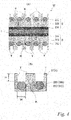
FIG. 3 , theelectrode layers catalyst layers gas diffusion layers gas diffusion layers electrolyte membrane 1. - The first
gas diffusion layers gas diffusion layers - The second
gas diffusion layer gas diffusion layers - Regarding structure, the second
gas diffusion layers gas diffusion layers FIG. 3 . When the secondgas diffusion layers gas diffusion layers - In the
electrode layers gas diffusion layers gas diffusion layers electrode layers gas diffusion layers gas diffusion layers - When the respective gases are supplied to the anode and
cathode electrode layers gas diffusion layers gas diffusion layers - In the single cells C, the metal porous bodies of the second gas diffusion layers 2C, 3C are hydrophilic compared to the first
gas diffusion layers gas diffusion layers - In contrast, in the single cells C according to this embodiment, the surfaces of the electrode layers 2, 3 have enhanced surface properties due to the fine uneven structure without water repellent finish to the second gas diffusion layers 2C, 3C. Furthermore, the surfaces of the electrode layers 2, 3 are also highly water repellent due to the first
gas diffusion layers separators 4 arc not increased, which contributes to improving the power generating function. - In the single cells C, the water repellent surface of the first
gas diffusion layers gas diffusion layers gas diffusion layers - Further, the contact angle on the surface of the electrode layers 2, 3 according to this embodiment was 160° (calculated value). That is, the fine uneven structure of the electrode layers 2, 3 allows water to form droplets on the protrusions T so as not to contact with the solid phase portion of the second gas diffusion layers 2C, 3C. It was demonstrated that high water repellency is thus obtained.
-
FIG. 4 illustrates a second embodiment of the present invention. In the following embodiment, the same reference signs are denoted to the same components as those of the first embodiment, and the detailed description thereof are omitted. - The single cell C in the figure has the same basic configuration as the first embodiment although the
separators 4 are not shown. Regarding protrusions T of firstgas diffusion layers gas diffusion layer - As with the previous embodiment, in the single cells C with the above-described configuration, the surface of the electrode layers 2, 3 have enhanced surface properties due to the fine uneven structure and are also highly water repellent due to the first
gas diffusion layers - Regarding protrusions T of first
gas diffusion layers FIG. 5 is configured such that the sum ((Va+Vb)×(1-ε1)) of the actual volume (Va×(1-ε1)) of the firstgas diffusion layers gas diffusion layers - In the above relation, the actual volume of the first
gas diffusion layers gas diffusion layers FIG. 5 (B) , and Vb is the total volume of the firstgas diffusion layers FIG. 5 (B) , which is equal to the volume of the hole K. In the above relation, the actual volume of the firstgas diffusion layer gas diffusion layers - As with the previous embodiments, in the single cells C with the above-described configuration, the surface of the electrode layers 2, 3 have enhanced surface properties due to the fine uneven structure and are also highly water repellent due to the first
gas diffusion layers separators 4, some af the protrusions T are squashed by theseparators 4 as illustrated in the lower part ofFIG. 5 (A) . - That is, since the single cell C is configured such that the sum of the actual volume of the first
gas diffusion layers gas diffusion layers gas diffusion layers separators 4 squash some protrusions T as illustrated in the figure to come in contact with the second gas diffusion layers 2C, 3C, which are constituted by a metal porous body, and the electrical contact resistance between them are thus reduced. Therefore, the power generation performance can be further improved. - As previously illustrated in
FIG. 5 , regarding protrusions T of firstgas diffusion layers gas diffusion layers gas diffusion layers - In this single cell C, the sum ((Va+Vb)×(1-ε1)) of the actual volume of the first
gas diffusion layer gas diffusion layer gas diffusion layers - More specifically, the actual volume (Vb×(1-ε2)) of the first
gas diffusion layers gas diffusion layers - As with the previous embodiments, in the single cell C with the above-described configuration, the surface of the electrode layers 2, 3 have enhanced surface properties due to the fine uneven structure and are also highly water repellent due to the first
gas diffusion layers separators 4, theseparators 4 squash the protrusions T as illustrated in the lower part ofFIG. 5 (A) to come in contact with the second gas diffusion layers 2C, 3C, the electrical contact resistance between them are thus reduced. Therefore, the power generation performance can be further improved. - Furthermore, in the single cells C, since the sum of the actual volume of the first
gas diffusion layer gas diffusion layer gas diffusion layers gas diffusion layers gas diffusion layers - In the single cell illustrated in
FIG. 6 , firstgas diffusion layers - The membrane electrode assembly M of the single cells according to the above-described embodiments can be formed by pressing the first and second
gas diffusion layers gas diffusion layers gas diffusion layers - In this process, in the membrane electrode assembly M, the porosity is inevitably decreased since the solid phase portions of the second gas diffusion layers 2C, 3C compress the first
gas diffusion layers gas diffusion layers gas diffusion layers - It is also effective that the first
gas diffusion layers gas diffusion layers gas diffusion layers - As with the previous embodiments, in the single cell C with the above-described configuration, the surface of the electrode layers 2, 3 have enhanced surface properties due to the fine uneven structure and are also highly water repellent due to the first
gas diffusion layers - The configuration of the fuel cell single cell according to the present invention is not limited to that of the above-described embodiments, and the details of the configuration may be suitably changed without departing from the gist of the present invention.
-
- FC
- Fuel cell
- G
- Gas channel
- K
- Hole
- M
- Membrane electrode assembly
- T
- Protrusion
- I
- Electrolyte membrane
- 2
- Electrode layer 2 (anode)
- 3
- Electrode layer 3 (cathode)
- 4
- Separator
- 2B, 3B
- First gas diffusion layer
- 2B1, 3B1
- Inner diffusion layer (first gus diffusion layer)
- 2B2, 3B2
- Outer diffusion layer (first gas diffusion layer)
- 2C, 3C
- Second gas diffusion layer
Claims (6)
- Fuel cell single cell, comprising:a membrane electrode assembly in which an electrolyte membrane is interposed between a pair of electrode layers; anda pair of separators that form gas channels between the pair of separators and the membrane electrode assembly,wherein the electrode layer of the membrane electrode assembly comprises a first gas diffusion layer of a porous material disposed on a side facing the electrolyte membrane and a second gas diffusion layer composed of a metal porous body with arrayed many holes, and a part of the first gas diffusion layer penetrates the second gas diffusion layer through the holes to form protrusions.
- The fuel cell single cell according to claim 1, wherein a surface of the first gas diffusion layer is water repellent.
- The fuel cell single cell according to claim 1 or 2, wherein each of the protrusions of the first gas diffusion layer and each of the respective holes of the second gas diffusion layer that corresponds to each other in a thickness direction satisfy a relation
in which a height of each of the protrusions is equal to or greater than a half of a width of a solid phase portion around each of the holes. - The fuel cell single cell according to any one of claims 1 to 3, wherein each of the protrusions of the first gas diffusion layer and each of the respective holes of the second gas diffusion layer that corresponds to each other in a thickness direction satisfy a relation
in which a sum of an actual volume of the first gas diffusion layer in each of the protrusions and an actual volume of the first gas diffusion layer in each of the holes is equal to or less than a volume of each of the holes. - The fuel cell single cell according to claim 4, wherein the sum of the actual volume of the first gas diffusion layer in each of the protrusions and the actual volume of the first gas diffusion layer in each of the holes are selected according to a porosity of the first gas diffusion layer after each of the protrusions is compressed into each of the holes.
- The fuel cell single cell according to any one of claims 1 ta 5, wherein the first gas diffusion layer comprises an inner diffusion layer on a side facing the electrolyte membrane and an outer diffusion layer on a side facing the second gas diffusion layer, and a part of the outer diffusion layer penetrates the second gas diffusion layers through the holes to protrude outward.
Applications Claiming Priority (2)
| Application Number | Priority Date | Filing Date | Title |
|---|---|---|---|
| JP2013144604 | 2013-07-10 | ||
| PCT/JP2014/061251 WO2015004969A1 (en) | 2013-07-10 | 2014-04-22 | Fuel cell unit cell |
Publications (3)
| Publication Number | Publication Date |
|---|---|
| EP3021392A1 true EP3021392A1 (en) | 2016-05-18 |
| EP3021392A4 EP3021392A4 (en) | 2016-07-13 |
| EP3021392B1 EP3021392B1 (en) | 2018-04-11 |
Family
ID=52279666
Family Applications (1)
| Application Number | Title | Priority Date | Filing Date |
|---|---|---|---|
| EP14822988.3A Not-in-force EP3021392B1 (en) | 2013-07-10 | 2014-04-22 | Fuel cell single cell |
Country Status (6)
| Country | Link |
|---|---|
| US (1) | US9837676B2 (en) |
| EP (1) | EP3021392B1 (en) |
| JP (1) | JP6066150B2 (en) |
| CN (1) | CN105531859B (en) |
| CA (1) | CA2917773C (en) |
| WO (1) | WO2015004969A1 (en) |
Cited By (1)
| Publication number | Priority date | Publication date | Assignee | Title |
|---|---|---|---|---|
| WO2023025516A3 (en) * | 2021-08-23 | 2023-04-20 | Robert Bosch Gmbh | Process for producing a gas diffusion layer |
Families Citing this family (5)
| Publication number | Priority date | Publication date | Assignee | Title |
|---|---|---|---|---|
| CN110752386B (en) * | 2019-09-20 | 2022-08-23 | 江苏大学 | Fuel cell bipolar plate and method |
| JP2022073337A (en) * | 2020-10-30 | 2022-05-17 | 本田技研工業株式会社 | Fuel cell separator and manufacturing method of fuel cell separator |
| JP7600908B2 (en) | 2021-07-05 | 2024-12-17 | トヨタ自動車株式会社 | Energy Storage Module |
| CN113659167B (en) * | 2021-07-09 | 2023-01-17 | 江苏大学 | Cathode runner of proton exchange membrane fuel cell for improving water removal effect |
| DE102022203467A1 (en) * | 2022-04-07 | 2023-10-12 | Robert Bosch Gesellschaft mit beschränkter Haftung | Diffusion layer for an electrochemical cell and method of producing a diffusion layer |
Family Cites Families (10)
| Publication number | Priority date | Publication date | Assignee | Title |
|---|---|---|---|---|
| US6007933A (en) * | 1998-04-27 | 1999-12-28 | Plug Power, L.L.C. | Fuel cell assembly unit for promoting fluid service and electrical conductivity |
| JP2004207088A (en) * | 2002-12-26 | 2004-07-22 | Nissan Motor Co Ltd | Gas permeable substrate and solid oxide fuel cell using the same |
| JP5061454B2 (en) | 2005-11-24 | 2012-10-31 | トヨタ自動車株式会社 | Fuel cell |
| US20070264550A1 (en) * | 2006-03-30 | 2007-11-15 | Magpower Systems Inc. | Air diffusion cathodes for fuel cells |
| JP2008204710A (en) * | 2007-02-19 | 2008-09-04 | Toyota Motor Corp | FUEL CELL, FUEL CELL CONNECTION AND MANUFACTURING METHOD |
| WO2008138396A1 (en) * | 2007-05-15 | 2008-11-20 | Acta S.P.A. | Vapor fed direct hydrocarbon alkaline fuel cells |
| JP2009245871A (en) | 2008-03-31 | 2009-10-22 | Mizuho Information & Research Institute Inc | Fuel cell, and electrode structure used for fuel cell |
| JP2010027243A (en) * | 2008-07-15 | 2010-02-04 | Toyota Motor Corp | Fuel cell |
| CN102484263B (en) * | 2009-09-03 | 2015-06-03 | 松下电器产业株式会社 | Gas diffusion layer for fuel cell, method for manufacturing same, membrane-electrode assembly, and fuel cell |
| CN104205460B (en) | 2012-04-04 | 2016-11-09 | 日产自动车株式会社 | The manufacture method of membrane electrode assembly, fuel cell, fuel cell pack and membrane electrode assembly |
-
2014
- 2014-04-22 EP EP14822988.3A patent/EP3021392B1/en not_active Not-in-force
- 2014-04-22 JP JP2015526191A patent/JP6066150B2/en not_active Expired - Fee Related
- 2014-04-22 US US14/903,632 patent/US9837676B2/en not_active Expired - Fee Related
- 2014-04-22 WO PCT/JP2014/061251 patent/WO2015004969A1/en not_active Ceased
- 2014-04-22 CN CN201480049814.2A patent/CN105531859B/en not_active Expired - Fee Related
- 2014-04-22 CA CA2917773A patent/CA2917773C/en active Active
Cited By (1)
| Publication number | Priority date | Publication date | Assignee | Title |
|---|---|---|---|---|
| WO2023025516A3 (en) * | 2021-08-23 | 2023-04-20 | Robert Bosch Gmbh | Process for producing a gas diffusion layer |
Also Published As
| Publication number | Publication date |
|---|---|
| US9837676B2 (en) | 2017-12-05 |
| EP3021392A4 (en) | 2016-07-13 |
| CN105531859B (en) | 2017-10-20 |
| EP3021392B1 (en) | 2018-04-11 |
| CA2917773C (en) | 2018-05-01 |
| CN105531859A (en) | 2016-04-27 |
| WO2015004969A1 (en) | 2015-01-15 |
| JP6066150B2 (en) | 2017-01-25 |
| JPWO2015004969A1 (en) | 2017-03-02 |
| US20160156053A1 (en) | 2016-06-02 |
| CA2917773A1 (en) | 2015-01-15 |
Similar Documents
| Publication | Publication Date | Title |
|---|---|---|
| EP3021392B1 (en) | Fuel cell single cell | |
| CN106575776B (en) | Flow Fields for Use with Electrochemical Cells | |
| JP6246203B2 (en) | Arrangement of flow structure for use in high differential pressure electrochemical cells | |
| US20110053030A1 (en) | Fuel Cell with Gas Diffusion Layer having Flow Channel and Manufacturing Method Thereof | |
| JP6360061B2 (en) | Elastic flow structure for electrochemical cells | |
| US9614232B2 (en) | Modular unit fuel cell assembly | |
| US7951284B2 (en) | Electrolysis apparatus, electrochemical reaction membrane apparatus, porous electrical conductor, and production method thereof | |
| JP2017516284A (en) | Flow field for use with electrochemical cells | |
| JP5400413B2 (en) | Electrolyzer | |
| EP2834870B1 (en) | Membrane electrode assembly, fuel cell, fuel cell stack, and method for manufacturing membrane electrode assembly | |
| CN105308216B (en) | End pressure plates for electrolyzers | |
| CN116888775A (en) | Bipolar plates for electrochemical cells, methods for manufacturing bipolar plates, components for electrochemical cells, and methods for operating components for electrochemical cells | |
| WO2025132726A1 (en) | Electrolysis cell component | |
| JP2017174563A (en) | Fuel cell |
Legal Events
| Date | Code | Title | Description |
|---|---|---|---|
| PUAI | Public reference made under article 153(3) epc to a published international application that has entered the european phase |
Free format text: ORIGINAL CODE: 0009012 |
|
| 17P | Request for examination filed |
Effective date: 20160210 |
|
| AK | Designated contracting states |
Kind code of ref document: A1 Designated state(s): AL AT BE BG CH CY CZ DE DK EE ES FI FR GB GR HR HU IE IS IT LI LT LU LV MC MK MT NL NO PL PT RO RS SE SI SK SM TR |
|
| AX | Request for extension of the european patent |
Extension state: BA ME |
|
| REG | Reference to a national code |
Ref country code: DE Ref legal event code: R079 Ref document number: 602014023878 Country of ref document: DE Free format text: PREVIOUS MAIN CLASS: H01M0004860000 Ipc: H01M0008023200 |
|
| A4 | Supplementary search report drawn up and despatched |
Effective date: 20160614 |
|
| RIC1 | Information provided on ipc code assigned before grant |
Ipc: H01M 8/0232 20160101AFI20160608BHEP Ipc: H01M 8/0245 20160101ALI20160608BHEP |
|
| DAX | Request for extension of the european patent (deleted) | ||
| 17Q | First examination report despatched |
Effective date: 20170511 |
|
| GRAP | Despatch of communication of intention to grant a patent |
Free format text: ORIGINAL CODE: EPIDOSNIGR1 |
|
| INTG | Intention to grant announced |
Effective date: 20171215 |
|
| GRAS | Grant fee paid |
Free format text: ORIGINAL CODE: EPIDOSNIGR3 |
|
| GRAA | (expected) grant |
Free format text: ORIGINAL CODE: 0009210 |
|
| AK | Designated contracting states |
Kind code of ref document: B1 Designated state(s): AL AT BE BG CH CY CZ DE DK EE ES FI FR GB GR HR HU IE IS IT LI LT LU LV MC MK MT NL NO PL PT RO RS SE SI SK SM TR |
|
| REG | Reference to a national code |
Ref country code: GB Ref legal event code: FG4D |
|
| REG | Reference to a national code |
Ref country code: CH Ref legal event code: EP |
|
| REG | Reference to a national code |
Ref country code: AT Ref legal event code: REF Ref document number: 988938 Country of ref document: AT Kind code of ref document: T Effective date: 20180415 |
|
| REG | Reference to a national code |
Ref country code: IE Ref legal event code: FG4D |
|
| REG | Reference to a national code |
Ref country code: DE Ref legal event code: R096 Ref document number: 602014023878 Country of ref document: DE |
|
| REG | Reference to a national code |
Ref country code: FR Ref legal event code: PLFP Year of fee payment: 5 |
|
| REG | Reference to a national code |
Ref country code: NL Ref legal event code: MP Effective date: 20180411 |
|
| REG | Reference to a national code |
Ref country code: LT Ref legal event code: MG4D |
|
| PG25 | Lapsed in a contracting state [announced via postgrant information from national office to epo] |
Ref country code: NL Free format text: LAPSE BECAUSE OF FAILURE TO SUBMIT A TRANSLATION OF THE DESCRIPTION OR TO PAY THE FEE WITHIN THE PRESCRIBED TIME-LIMIT Effective date: 20180411 |
|
| PG25 | Lapsed in a contracting state [announced via postgrant information from national office to epo] |
Ref country code: SE Free format text: LAPSE BECAUSE OF FAILURE TO SUBMIT A TRANSLATION OF THE DESCRIPTION OR TO PAY THE FEE WITHIN THE PRESCRIBED TIME-LIMIT Effective date: 20180411 Ref country code: PL Free format text: LAPSE BECAUSE OF FAILURE TO SUBMIT A TRANSLATION OF THE DESCRIPTION OR TO PAY THE FEE WITHIN THE PRESCRIBED TIME-LIMIT Effective date: 20180411 Ref country code: LT Free format text: LAPSE BECAUSE OF FAILURE TO SUBMIT A TRANSLATION OF THE DESCRIPTION OR TO PAY THE FEE WITHIN THE PRESCRIBED TIME-LIMIT Effective date: 20180411 Ref country code: ES Free format text: LAPSE BECAUSE OF FAILURE TO SUBMIT A TRANSLATION OF THE DESCRIPTION OR TO PAY THE FEE WITHIN THE PRESCRIBED TIME-LIMIT Effective date: 20180411 Ref country code: AL Free format text: LAPSE BECAUSE OF FAILURE TO SUBMIT A TRANSLATION OF THE DESCRIPTION OR TO PAY THE FEE WITHIN THE PRESCRIBED TIME-LIMIT Effective date: 20180411 Ref country code: NO Free format text: LAPSE BECAUSE OF FAILURE TO SUBMIT A TRANSLATION OF THE DESCRIPTION OR TO PAY THE FEE WITHIN THE PRESCRIBED TIME-LIMIT Effective date: 20180711 Ref country code: BG Free format text: LAPSE BECAUSE OF FAILURE TO SUBMIT A TRANSLATION OF THE DESCRIPTION OR TO PAY THE FEE WITHIN THE PRESCRIBED TIME-LIMIT Effective date: 20180711 Ref country code: FI Free format text: LAPSE BECAUSE OF FAILURE TO SUBMIT A TRANSLATION OF THE DESCRIPTION OR TO PAY THE FEE WITHIN THE PRESCRIBED TIME-LIMIT Effective date: 20180411 |
|
| PG25 | Lapsed in a contracting state [announced via postgrant information from national office to epo] |
Ref country code: RS Free format text: LAPSE BECAUSE OF FAILURE TO SUBMIT A TRANSLATION OF THE DESCRIPTION OR TO PAY THE FEE WITHIN THE PRESCRIBED TIME-LIMIT Effective date: 20180411 Ref country code: HR Free format text: LAPSE BECAUSE OF FAILURE TO SUBMIT A TRANSLATION OF THE DESCRIPTION OR TO PAY THE FEE WITHIN THE PRESCRIBED TIME-LIMIT Effective date: 20180411 Ref country code: GR Free format text: LAPSE BECAUSE OF FAILURE TO SUBMIT A TRANSLATION OF THE DESCRIPTION OR TO PAY THE FEE WITHIN THE PRESCRIBED TIME-LIMIT Effective date: 20180712 Ref country code: LV Free format text: LAPSE BECAUSE OF FAILURE TO SUBMIT A TRANSLATION OF THE DESCRIPTION OR TO PAY THE FEE WITHIN THE PRESCRIBED TIME-LIMIT Effective date: 20180411 |
|
| REG | Reference to a national code |
Ref country code: CH Ref legal event code: PL |
|
| REG | Reference to a national code |
Ref country code: AT Ref legal event code: MK05 Ref document number: 988938 Country of ref document: AT Kind code of ref document: T Effective date: 20180411 |
|
| REG | Reference to a national code |
Ref country code: BE Ref legal event code: MM Effective date: 20180430 |
|
| PG25 | Lapsed in a contracting state [announced via postgrant information from national office to epo] |
Ref country code: PT Free format text: LAPSE BECAUSE OF FAILURE TO SUBMIT A TRANSLATION OF THE DESCRIPTION OR TO PAY THE FEE WITHIN THE PRESCRIBED TIME-LIMIT Effective date: 20180813 |
|
| REG | Reference to a national code |
Ref country code: DE Ref legal event code: R097 Ref document number: 602014023878 Country of ref document: DE |
|
| REG | Reference to a national code |
Ref country code: IE Ref legal event code: MM4A |
|
| PG25 | Lapsed in a contracting state [announced via postgrant information from national office to epo] |
Ref country code: MC Free format text: LAPSE BECAUSE OF FAILURE TO SUBMIT A TRANSLATION OF THE DESCRIPTION OR TO PAY THE FEE WITHIN THE PRESCRIBED TIME-LIMIT Effective date: 20180411 Ref country code: DK Free format text: LAPSE BECAUSE OF FAILURE TO SUBMIT A TRANSLATION OF THE DESCRIPTION OR TO PAY THE FEE WITHIN THE PRESCRIBED TIME-LIMIT Effective date: 20180411 Ref country code: AT Free format text: LAPSE BECAUSE OF FAILURE TO SUBMIT A TRANSLATION OF THE DESCRIPTION OR TO PAY THE FEE WITHIN THE PRESCRIBED TIME-LIMIT Effective date: 20180411 Ref country code: EE Free format text: LAPSE BECAUSE OF FAILURE TO SUBMIT A TRANSLATION OF THE DESCRIPTION OR TO PAY THE FEE WITHIN THE PRESCRIBED TIME-LIMIT Effective date: 20180411 Ref country code: LU Free format text: LAPSE BECAUSE OF NON-PAYMENT OF DUE FEES Effective date: 20180422 Ref country code: RO Free format text: LAPSE BECAUSE OF FAILURE TO SUBMIT A TRANSLATION OF THE DESCRIPTION OR TO PAY THE FEE WITHIN THE PRESCRIBED TIME-LIMIT Effective date: 20180411 Ref country code: SK Free format text: LAPSE BECAUSE OF FAILURE TO SUBMIT A TRANSLATION OF THE DESCRIPTION OR TO PAY THE FEE WITHIN THE PRESCRIBED TIME-LIMIT Effective date: 20180411 Ref country code: CZ Free format text: LAPSE BECAUSE OF FAILURE TO SUBMIT A TRANSLATION OF THE DESCRIPTION OR TO PAY THE FEE WITHIN THE PRESCRIBED TIME-LIMIT Effective date: 20180411 |
|
| PLBE | No opposition filed within time limit |
Free format text: ORIGINAL CODE: 0009261 |
|
| STAA | Information on the status of an ep patent application or granted ep patent |
Free format text: STATUS: NO OPPOSITION FILED WITHIN TIME LIMIT |
|
| PG25 | Lapsed in a contracting state [announced via postgrant information from national office to epo] |
Ref country code: CH Free format text: LAPSE BECAUSE OF NON-PAYMENT OF DUE FEES Effective date: 20180430 Ref country code: BE Free format text: LAPSE BECAUSE OF NON-PAYMENT OF DUE FEES Effective date: 20180430 Ref country code: LI Free format text: LAPSE BECAUSE OF NON-PAYMENT OF DUE FEES Effective date: 20180430 Ref country code: IT Free format text: LAPSE BECAUSE OF FAILURE TO SUBMIT A TRANSLATION OF THE DESCRIPTION OR TO PAY THE FEE WITHIN THE PRESCRIBED TIME-LIMIT Effective date: 20180411 Ref country code: SM Free format text: LAPSE BECAUSE OF FAILURE TO SUBMIT A TRANSLATION OF THE DESCRIPTION OR TO PAY THE FEE WITHIN THE PRESCRIBED TIME-LIMIT Effective date: 20180411 |
|
| 26N | No opposition filed |
Effective date: 20190114 |
|
| PG25 | Lapsed in a contracting state [announced via postgrant information from national office to epo] |
Ref country code: IE Free format text: LAPSE BECAUSE OF NON-PAYMENT OF DUE FEES Effective date: 20180422 |
|
| PG25 | Lapsed in a contracting state [announced via postgrant information from national office to epo] |
Ref country code: SI Free format text: LAPSE BECAUSE OF FAILURE TO SUBMIT A TRANSLATION OF THE DESCRIPTION OR TO PAY THE FEE WITHIN THE PRESCRIBED TIME-LIMIT Effective date: 20180411 |
|
| PG25 | Lapsed in a contracting state [announced via postgrant information from national office to epo] |
Ref country code: MT Free format text: LAPSE BECAUSE OF NON-PAYMENT OF DUE FEES Effective date: 20180422 |
|
| PG25 | Lapsed in a contracting state [announced via postgrant information from national office to epo] |
Ref country code: TR Free format text: LAPSE BECAUSE OF FAILURE TO SUBMIT A TRANSLATION OF THE DESCRIPTION OR TO PAY THE FEE WITHIN THE PRESCRIBED TIME-LIMIT Effective date: 20180411 |
|
| PG25 | Lapsed in a contracting state [announced via postgrant information from national office to epo] |
Ref country code: CY Free format text: LAPSE BECAUSE OF FAILURE TO SUBMIT A TRANSLATION OF THE DESCRIPTION OR TO PAY THE FEE WITHIN THE PRESCRIBED TIME-LIMIT Effective date: 20180411 Ref country code: MK Free format text: LAPSE BECAUSE OF NON-PAYMENT OF DUE FEES Effective date: 20180411 Ref country code: HU Free format text: LAPSE BECAUSE OF FAILURE TO SUBMIT A TRANSLATION OF THE DESCRIPTION OR TO PAY THE FEE WITHIN THE PRESCRIBED TIME-LIMIT; INVALID AB INITIO Effective date: 20140422 |
|
| PG25 | Lapsed in a contracting state [announced via postgrant information from national office to epo] |
Ref country code: IS Free format text: LAPSE BECAUSE OF FAILURE TO SUBMIT A TRANSLATION OF THE DESCRIPTION OR TO PAY THE FEE WITHIN THE PRESCRIBED TIME-LIMIT Effective date: 20180811 |
|
| PGFP | Annual fee paid to national office [announced via postgrant information from national office to epo] |
Ref country code: GB Payment date: 20220303 Year of fee payment: 9 |
|
| PGFP | Annual fee paid to national office [announced via postgrant information from national office to epo] |
Ref country code: FR Payment date: 20220308 Year of fee payment: 9 |
|
| PGFP | Annual fee paid to national office [announced via postgrant information from national office to epo] |
Ref country code: DE Payment date: 20220302 Year of fee payment: 9 |
|
| REG | Reference to a national code |
Ref country code: DE Ref legal event code: R119 Ref document number: 602014023878 Country of ref document: DE |
|
| GBPC | Gb: european patent ceased through non-payment of renewal fee |
Effective date: 20230422 |
|
| PG25 | Lapsed in a contracting state [announced via postgrant information from national office to epo] |
Ref country code: GB Free format text: LAPSE BECAUSE OF NON-PAYMENT OF DUE FEES Effective date: 20230422 |
|
| PG25 | Lapsed in a contracting state [announced via postgrant information from national office to epo] |
Ref country code: GB Free format text: LAPSE BECAUSE OF NON-PAYMENT OF DUE FEES Effective date: 20230422 Ref country code: FR Free format text: LAPSE BECAUSE OF NON-PAYMENT OF DUE FEES Effective date: 20230430 Ref country code: DE Free format text: LAPSE BECAUSE OF NON-PAYMENT OF DUE FEES Effective date: 20231103 |