EP3021037A1 - Light bar - Google Patents
Light bar Download PDFInfo
- Publication number
- EP3021037A1 EP3021037A1 EP15193051.8A EP15193051A EP3021037A1 EP 3021037 A1 EP3021037 A1 EP 3021037A1 EP 15193051 A EP15193051 A EP 15193051A EP 3021037 A1 EP3021037 A1 EP 3021037A1
- Authority
- EP
- European Patent Office
- Prior art keywords
- light bar
- substrate
- optical component
- housing
- light
- Prior art date
- Legal status (The legal status is an assumption and is not a legal conclusion. Google has not performed a legal analysis and makes no representation as to the accuracy of the status listed.)
- Granted
Links
- 239000000758 substrate Substances 0.000 claims abstract description 77
- 230000003287 optical effect Effects 0.000 claims abstract description 57
- 238000000034 method Methods 0.000 claims description 7
- 230000008569 process Effects 0.000 claims description 7
- 238000002347 injection Methods 0.000 claims description 6
- 239000007924 injection Substances 0.000 claims description 6
- 238000001125 extrusion Methods 0.000 claims description 4
- 238000007789 sealing Methods 0.000 claims description 3
- 238000005057 refrigeration Methods 0.000 abstract description 29
- 239000000463 material Substances 0.000 description 5
- 235000013305 food Nutrition 0.000 description 4
- 238000004519 manufacturing process Methods 0.000 description 3
- 230000004048 modification Effects 0.000 description 3
- 238000012986 modification Methods 0.000 description 3
- 229920000515 polycarbonate Polymers 0.000 description 3
- 239000004417 polycarbonate Substances 0.000 description 3
- 239000012815 thermoplastic material Substances 0.000 description 3
- 235000013361 beverage Nutrition 0.000 description 2
- 238000010586 diagram Methods 0.000 description 2
- 230000000007 visual effect Effects 0.000 description 2
- 239000000654 additive Substances 0.000 description 1
- 230000005540 biological transmission Effects 0.000 description 1
- 238000010276 construction Methods 0.000 description 1
- 235000013410 fast food Nutrition 0.000 description 1
- 238000005286 illumination Methods 0.000 description 1
- 230000004044 response Effects 0.000 description 1
- 238000006467 substitution reaction Methods 0.000 description 1
- 229920001169 thermoplastic Polymers 0.000 description 1
- 239000004416 thermosoftening plastic Substances 0.000 description 1
- 239000012780 transparent material Substances 0.000 description 1
Images

Classifications
-
- F—MECHANICAL ENGINEERING; LIGHTING; HEATING; WEAPONS; BLASTING
- F21—LIGHTING
- F21K—NON-ELECTRIC LIGHT SOURCES USING LUMINESCENCE; LIGHT SOURCES USING ELECTROCHEMILUMINESCENCE; LIGHT SOURCES USING CHARGES OF COMBUSTIBLE MATERIAL; LIGHT SOURCES USING SEMICONDUCTOR DEVICES AS LIGHT-GENERATING ELEMENTS; LIGHT SOURCES NOT OTHERWISE PROVIDED FOR
- F21K9/00—Light sources using semiconductor devices as light-generating elements, e.g. using light-emitting diodes [LED] or lasers
- F21K9/20—Light sources comprising attachment means
- F21K9/27—Retrofit light sources for lighting devices with two fittings for each light source, e.g. for substitution of fluorescent tubes
-
- A—HUMAN NECESSITIES
- A47—FURNITURE; DOMESTIC ARTICLES OR APPLIANCES; COFFEE MILLS; SPICE MILLS; SUCTION CLEANERS IN GENERAL
- A47F—SPECIAL FURNITURE, FITTINGS, OR ACCESSORIES FOR SHOPS, STOREHOUSES, BARS, RESTAURANTS OR THE LIKE; PAYING COUNTERS
- A47F3/00—Show cases or show cabinets
- A47F3/001—Devices for lighting, humidifying, heating, ventilation
-
- A—HUMAN NECESSITIES
- A47—FURNITURE; DOMESTIC ARTICLES OR APPLIANCES; COFFEE MILLS; SPICE MILLS; SUCTION CLEANERS IN GENERAL
- A47F—SPECIAL FURNITURE, FITTINGS, OR ACCESSORIES FOR SHOPS, STOREHOUSES, BARS, RESTAURANTS OR THE LIKE; PAYING COUNTERS
- A47F3/00—Show cases or show cabinets
- A47F3/04—Show cases or show cabinets air-conditioned, refrigerated
- A47F3/0482—Details common to both closed and open types
- A47F3/0486—Details common to both closed and open types for charging, displaying or discharging the articles
- A47F3/0491—Cooled shelves
-
- A—HUMAN NECESSITIES
- A47—FURNITURE; DOMESTIC ARTICLES OR APPLIANCES; COFFEE MILLS; SPICE MILLS; SUCTION CLEANERS IN GENERAL
- A47F—SPECIAL FURNITURE, FITTINGS, OR ACCESSORIES FOR SHOPS, STOREHOUSES, BARS, RESTAURANTS OR THE LIKE; PAYING COUNTERS
- A47F7/00—Show stands, hangers, or shelves, adapted for particular articles or materials
- A47F7/0071—Show stands, hangers, or shelves, adapted for particular articles or materials for perishable goods
-
- F—MECHANICAL ENGINEERING; LIGHTING; HEATING; WEAPONS; BLASTING
- F21—LIGHTING
- F21S—NON-PORTABLE LIGHTING DEVICES; SYSTEMS THEREOF; VEHICLE LIGHTING DEVICES SPECIALLY ADAPTED FOR VEHICLE EXTERIORS
- F21S4/00—Lighting devices or systems using a string or strip of light sources
- F21S4/20—Lighting devices or systems using a string or strip of light sources with light sources held by or within elongate supports
- F21S4/28—Lighting devices or systems using a string or strip of light sources with light sources held by or within elongate supports rigid, e.g. LED bars
-
- F—MECHANICAL ENGINEERING; LIGHTING; HEATING; WEAPONS; BLASTING
- F21—LIGHTING
- F21V—FUNCTIONAL FEATURES OR DETAILS OF LIGHTING DEVICES OR SYSTEMS THEREOF; STRUCTURAL COMBINATIONS OF LIGHTING DEVICES WITH OTHER ARTICLES, NOT OTHERWISE PROVIDED FOR
- F21V11/00—Screens not covered by groups F21V1/00, F21V3/00, F21V7/00 or F21V9/00
-
- F—MECHANICAL ENGINEERING; LIGHTING; HEATING; WEAPONS; BLASTING
- F21—LIGHTING
- F21V—FUNCTIONAL FEATURES OR DETAILS OF LIGHTING DEVICES OR SYSTEMS THEREOF; STRUCTURAL COMBINATIONS OF LIGHTING DEVICES WITH OTHER ARTICLES, NOT OTHERWISE PROVIDED FOR
- F21V5/00—Refractors for light sources
- F21V5/04—Refractors for light sources of lens shape
-
- F—MECHANICAL ENGINEERING; LIGHTING; HEATING; WEAPONS; BLASTING
- F21—LIGHTING
- F21V—FUNCTIONAL FEATURES OR DETAILS OF LIGHTING DEVICES OR SYSTEMS THEREOF; STRUCTURAL COMBINATIONS OF LIGHTING DEVICES WITH OTHER ARTICLES, NOT OTHERWISE PROVIDED FOR
- F21V7/00—Reflectors for light sources
- F21V7/005—Reflectors for light sources with an elongated shape to cooperate with linear light sources
-
- F—MECHANICAL ENGINEERING; LIGHTING; HEATING; WEAPONS; BLASTING
- F21—LIGHTING
- F21V—FUNCTIONAL FEATURES OR DETAILS OF LIGHTING DEVICES OR SYSTEMS THEREOF; STRUCTURAL COMBINATIONS OF LIGHTING DEVICES WITH OTHER ARTICLES, NOT OTHERWISE PROVIDED FOR
- F21V11/00—Screens not covered by groups F21V1/00, F21V3/00, F21V7/00 or F21V9/00
- F21V11/16—Screens not covered by groups F21V1/00, F21V3/00, F21V7/00 or F21V9/00 using sheets without apertures, e.g. fixed
-
- F—MECHANICAL ENGINEERING; LIGHTING; HEATING; WEAPONS; BLASTING
- F21—LIGHTING
- F21V—FUNCTIONAL FEATURES OR DETAILS OF LIGHTING DEVICES OR SYSTEMS THEREOF; STRUCTURAL COMBINATIONS OF LIGHTING DEVICES WITH OTHER ARTICLES, NOT OTHERWISE PROVIDED FOR
- F21V13/00—Producing particular characteristics or distribution of the light emitted by means of a combination of elements specified in two or more of main groups F21V1/00 - F21V11/00
- F21V13/02—Combinations of only two kinds of elements
- F21V13/04—Combinations of only two kinds of elements the elements being reflectors and refractors
-
- F—MECHANICAL ENGINEERING; LIGHTING; HEATING; WEAPONS; BLASTING
- F21—LIGHTING
- F21V—FUNCTIONAL FEATURES OR DETAILS OF LIGHTING DEVICES OR SYSTEMS THEREOF; STRUCTURAL COMBINATIONS OF LIGHTING DEVICES WITH OTHER ARTICLES, NOT OTHERWISE PROVIDED FOR
- F21V15/00—Protecting lighting devices from damage
- F21V15/01—Housings, e.g. material or assembling of housing parts
- F21V15/013—Housings, e.g. material or assembling of housing parts the housing being an extrusion
-
- F—MECHANICAL ENGINEERING; LIGHTING; HEATING; WEAPONS; BLASTING
- F21—LIGHTING
- F21V—FUNCTIONAL FEATURES OR DETAILS OF LIGHTING DEVICES OR SYSTEMS THEREOF; STRUCTURAL COMBINATIONS OF LIGHTING DEVICES WITH OTHER ARTICLES, NOT OTHERWISE PROVIDED FOR
- F21V5/00—Refractors for light sources
- F21V5/08—Refractors for light sources producing an asymmetric light distribution
-
- F—MECHANICAL ENGINEERING; LIGHTING; HEATING; WEAPONS; BLASTING
- F21—LIGHTING
- F21W—INDEXING SCHEME ASSOCIATED WITH SUBCLASSES F21K, F21L, F21S and F21V, RELATING TO USES OR APPLICATIONS OF LIGHTING DEVICES OR SYSTEMS
- F21W2131/00—Use or application of lighting devices or systems not provided for in codes F21W2102/00-F21W2121/00
- F21W2131/40—Lighting for industrial, commercial, recreational or military use
- F21W2131/405—Lighting for industrial, commercial, recreational or military use for shop-windows or displays
-
- F—MECHANICAL ENGINEERING; LIGHTING; HEATING; WEAPONS; BLASTING
- F21—LIGHTING
- F21Y—INDEXING SCHEME ASSOCIATED WITH SUBCLASSES F21K, F21L, F21S and F21V, RELATING TO THE FORM OR THE KIND OF THE LIGHT SOURCES OR OF THE COLOUR OF THE LIGHT EMITTED
- F21Y2103/00—Elongate light sources, e.g. fluorescent tubes
- F21Y2103/10—Elongate light sources, e.g. fluorescent tubes comprising a linear array of point-like light-generating elements
-
- F—MECHANICAL ENGINEERING; LIGHTING; HEATING; WEAPONS; BLASTING
- F21—LIGHTING
- F21Y—INDEXING SCHEME ASSOCIATED WITH SUBCLASSES F21K, F21L, F21S and F21V, RELATING TO THE FORM OR THE KIND OF THE LIGHT SOURCES OR OF THE COLOUR OF THE LIGHT EMITTED
- F21Y2107/00—Light sources with three-dimensionally disposed light-generating elements
- F21Y2107/90—Light sources with three-dimensionally disposed light-generating elements on two opposite sides of supports or substrates
-
- F—MECHANICAL ENGINEERING; LIGHTING; HEATING; WEAPONS; BLASTING
- F21—LIGHTING
- F21Y—INDEXING SCHEME ASSOCIATED WITH SUBCLASSES F21K, F21L, F21S and F21V, RELATING TO THE FORM OR THE KIND OF THE LIGHT SOURCES OR OF THE COLOUR OF THE LIGHT EMITTED
- F21Y2115/00—Light-generating elements of semiconductor light sources
- F21Y2115/10—Light-emitting diodes [LED]
Definitions
- This disclosure relates generally to a light fixture, and more particularly to a light bar for illuminating a product display area and used in a display cabinet.
- refrigeration displays In conventional practice, commercial establishments such as supermarkets, convenience stores, delis and fast food restaurants are usually equipped with refrigeration displays.
- the refrigeration displays may be open or provided with doors and are used for presenting perishable food or beverages to customers while maintaining the fresh food or beverages in a refrigerated environment.
- the refrigeration displays include a light bar to illuminate a product display area for better marketing of the food product and for higher visibility of the customers.
- the light bars of the conventional refrigeration displays typically use a fluorescent light source to illuminate the product display area.
- the fluorescent light sources are coupled to a canopy of the refrigeration display to direct light generally downward onto the food product in the product display area.
- the fluorescent light sources may also be attached to shelves in the product display area.
- the fluorescent light sources used in the conventional refrigeration displays are relatively large.
- LED light sources are becoming more prevalent as replacements for the conventional light sources such as the fluorescent light source.
- the LED light sources are widely applied to the illumination system because they have such many advantages as small size, low power consumption, longer lifetime, high luminous efficiency, fast response and etc.
- the light bar using the LED light sources in the conventional refrigeration display is usually very complex in structure, resulting in higher product cost.
- a light bar comprises an optical component, a housing for reflecting light and a substrate assembly.
- the optical component and the housing together form a tube with a cavity.
- the substrate assembly is held in the cavity and comprises a substrate and a plurality of LED light sources mounted on at least one side of the substrate. Light emitted from the plurality of LED light sources is irradiated to at least one predetermined area perpendicular to the substrate after passing through the optical component.
- a refrigeration display comprises a plurality of shelves for holding product, at least one mullion having a mounting surface and a vertically extending light bar positioned within the interior of the refrigeration display behind the at least one mullion and forward of the shelves.
- the light bar comprises an optical component, a housing for reflecting light and a substrate assembly.
- the optical component and the housing together form a tube with a cavity.
- the substrate assembly is slidably held in the cavity and comprises a substrate perpendicular to the mounting surface of the at least one mullion and a plurality of LED light sources mounted on at least one side of the substrate. Light emitted from the plurality of LED light sources is irradiated to the shelves after passing through the optical component.
- FIGS. 1-4 illustrate schematic diagrams of a light bar in accordance with a first embodiment of the present invention.
- the light bar in accordance with the first embodiment of the present invention includes an optical component 11, a housing 12 for reflecting light and a substrate assembly 14.
- the optical component 11 and the housing 12 extend longitudinally, and the optical component 11 and the housing 12 together form a tube 10 with a cavity 13.
- the substrate assembly 14 is held in the cavity 13 of the tube 10 and comprises a substrate 141 and a plurality of LED light sources 142 mounted on the substrate 141. Light emitted from the plurality of LED light sources 142 can be irradiated to at least one predetermined area perpendicular to the substrate 141 after passing through the optical component 11.
- the light bar 1 of the first embodiment is simple in structure and easy to assemble and has lower manufacturing cost. Furthermore, the light bar 1 can adopt multiple low power LED light sources 142, thereby further reducing product cost.
- the optical component 11 may be refractive or act as a lens, or the optical component 11 may be simply transmissive or translucent.
- the optical component 11 may be comprised of transparent or translucent polycarbonate, for example, or any other thermoplastic material which is transparent or translucent in operation, and which may be capable of being extruded or injection molded.
- the housing 12 may be an opaque or diffusive component which generally blocks the transmission of light.
- the housing 12 may be made from a reflective material.
- the housing 12 may also be made from a light-transmitting material which is covered by a layer of light-blocking material.
- the housing 12 may made from a transparent material covered with a layer of opaque material.
- the housing 12 may also be comprised of a polycarbonate material, which comprises additives that make it opaque or diffusive.
- the opaque or diffusive component acting as the housing 12 may comprise other thermoplastic materials which do not pass light.
- the housing 12 may also be capable of being extruded or injection molded.
- the optical component 11 and the housing 12 may be made of suitably compatible thermoplastics, so the optical component 11 and the housing 12 may be made by a co-injection process or a co-extrusion process.
- the optical component 11 and the housing 12 are integrated together to form the tube 10 with the cavity 13.
- the optical component 11 and the housing 12 are both made of polycarbonate, one is transparent or translucent, and the other is made to not be transparent or translucent, which may facilitate fabrication by a co-injection process or a co-extrusion process.
- the optical component 11 and the housing 12 can also be made of different kinds of thermoplastic materials.
- the housing 12 comprises a mounting wall 121 substantially extending longitudinally.
- the mounting wall 121 of the housing 12 is configured to be mounted onto a mullion of a display cabinet (not shown) so that the light bar 1 is fixed onto the mullion of the display cabinet.
- the substrate assembly 14 is slidably and perpendicularly mounted in the mounting wall 121 of the housing 12 so as to distribute the light emitted from the plurality of LED light sources 142 wider and easier.
- the substrate 141 has the shape of a slab.
- the slab-shaped substrate 141 has opposite two sides.
- the substrate 141 is for example a printed circuit board (PCB).
- PCB printed circuit board
- the substrate 141 of the present invention should be not limited to the PCB.
- the plurality of LED light sources 142 are mounted on opposite two sides of the substrate 141, and the light emitted from the plurality of LED light sources 142 can be irradiated to opposite two predetermined areas after passing through the optical component 11.
- the light bar 1 has two halves which are symmetrical relative to the substrate 141. So the optical component 11 has two halves which are symmetrical relative to the substrate 141 and the housing 12 also has two halves which are symmetrical relative to the substrate 141. In an embodiment, the optical component 11 has a substantially dome-shaped cross-section. Each of the two halves of the optical component 11 has different thickness. The optical component 11 can control the light emitted from the plurality of LED light sources 142 to shine a surface perpendicular to a substrate direction. The shape of the cross-section of the optical component 11 can be properly changed according to user's requirements so that the light emitted from the plurality of LED light sources 142 can be irradiated to a desired display area.
- the optical component 11 defines a first longitudinal channel 110 at a junction of the two halves thereof and the housing 12 defines a second longitudinal channel 120 at a junction of the two halves thereof.
- the substrate assembly 14 is slidably mounted between the first longitudinal channel 110 of the optical component 11 and the second longitudinal channel 120 of the housing 12 so that the substrate assembly 14 is held in the cavity 13 of the tube 10.
- the housing 12 may further comprise a pair of anti-dazzle wings 124 extending from opposite two lateral sides of the mounting wall 121 beyond the optical component 11.
- the pair of wings 124 can block light from the optical component 11 to enter eyes of the user who is on the side of the housing 12, which brings the user better visual effects.
- the light bar 1 further comprises a pair of end caps 16 attached to ends of the tube 10 for sealing the cavity 13.
- One of the pair of end caps 16 defines a hole (not shown) therein and the substrate assembly 14 further comprises a wire harness 143 connecting with the substrate 141.
- the wire harness 143 extends out of the tube 10 through the hole of the end cap 16 for connecting to an external controlling circuit.
- the end cap 16 has a matching structure with the tube 10 so that the light bar 1 has a uniform appearance.
- the plurality of LED light sources 142 are first mounted on the substrate 141 to form the substrate assembly 14. Then the substrate 141 with the plurality of LED light sources 142, i.e. the substrate assembly 14 is inserted to the cavity 13 of the tube 10 and slidably held between the first longitudinal channel 110 of the optical component 11 and the second longitudinal channel 120 of the housing 12. Finally, the pair of end caps 16 are attached to the ends of the tube 10. The assembly of the light bar 1 is easily finished.
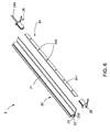
- FIGS. 5-8 illustrate schematic diagrams of a light bar in accordance with a second embodiment of the present invention.
- the light bar 2 in accordance with the second embodiment also includes an optical component 21, a housing 22 for reflecting light and a substrate assembly 24.
- the optical component 21 and the housing 22 together form a tube 20 with a cavity 23.
- the substrate assembly 24 is held in the cavity 23 of the tube 20 and comprises a substrate 241, a plurality of LED light sources 242 mounted on the substrate 241, and a wire harness 243 connecting with the substrate 241.
- the optical component 21 and the housing 22 are integrated together to form the tube 20 with the cavity 23 by a co-injection process or a co-extrusion process.
- the optical component 21 has different thickness.
- the optical component 21 can control the light emitted from the plurality of LED light sources 242 to shine a surface perpendicular to a substrate direction.
- the shape of the cross-section of the optical component 21 can be properly changed according to user's requirements so that the light emitted from the plurality of LED light sources 242 can be irradiated to a desired display area.
- the light bar 2 of the second embodiment has substantially only one half of the light bar 1 of the first embodiment.
- the plurality of LED light sources 242 are mounted on only one side of the substrate 241, and the light emitted from the plurality of LED light sources 242 is irradiated to a predetermined area after passing through the optical component 21.
- the housing 22 comprises a mounting wall 221 substantially extending longitudinally and a vertical wall 222 substantially extending vertically from one lateral side of the mounting wall 221.
- the substrate assembly 24 is installed immediately adjacent to the vertical wall 222 of the housing 22, so the substrate assembly 24 is perpendicular to the mounting wall 221 of the housing 22.
- the housing 22 defines a longitudinal channel 220 at a junction of the vertical wall 222 and the mounting wall 221.
- the substrate assembly 24 is slidably mounted in the longitudinal channel 220 of the housing 22 so that the substrate assembly 24 is held in the cavity 23 of the tube 20.
- the housing 22 further comprises an anti-dazzle wing 224 extending from an opposite lateral side of the mounting wall 221 beyond the optical component 21.
- the wing 224 can block light from the optical component 21 to enter eyes of the user who is on the side of the housing 22, which brings the user better visual effects.
- the light bar 2 further comprises a pair of end caps 26 attached to ends of the tube 20 for sealing the cavity 23.
- One of the pair of end caps 26 defines a hole (not shown) therein and the wire harness 243 connecting with the substrate 241 extends out of the tube 20 through the hole of the end cap 26.
- the end cap 26 has a matching structure with the tube 20 so that the light bar 2 has a uniform appearance.
- the plurality of LED light sources 242 are first mounted on the substrate 241 to form the substrate assembly 24. Then the substrate 241 with the plurality of LED light sources 242, i.e. the substrate assembly 24 is inserted slidably into the longitudinal channel 220 of the housing 22 and is held in the cavity 23 of the tube 20. Finally, the pair of end caps 26 are attached to the ends of the tube 20. The assembly of the light bar 2 is easily finished.
- the light bars 1 and 2 of the present invention are simple in structure and easy to assemble and has lower manufacturing cost. Furthermore, the light bars 1 and 2 can adopt multiple low power LED light sources 142 and 242, thereby further reducing product cost.
- the light bar 1, 2 of the present invention can be applied to a refrigeration display (not shown).
- the refrigeration display comprises a plurality of shelves for holding product and at least one mullion having a mounting surface.
- the vertically extending light bar 1, 2 of the present invention can be positioned within the interior of the refrigeration display behind the at least one mullion and forward of the shelves.
- the substrate 141, 241 of the light bar 1, 2 is perpendicular to the mounting surface of the at least one mullion.
- the light emitted from the plurality of LED light sources 142, 242 can be irradiated to the shelves of the refrigeration display after passing through the optical component 11,21 of the light bar 1, 2.
- the light bar 1 of the first embodiment and the light bar 2 of the second embodiment can be used in different cases.
- the light bar 2 of the second embodiment can be adopted.
- the light bar 1 of the first embodiment can be adopted.
- the light bar 2 of the second embodiment and the light bar 1 of the first embodiment can be adopted.
- the refrigeration display can use the light bar 1 of the first embodiment.
- the light bar 1 of the first embodiment is positioned behind the central mullion and forward of the shelves.
- the refrigeration display is in operation, the light emitted from the plurality of LED light sources 142 on opposite two sides of the substrate 141 of the light bar 1 can be irradiated to the shelves on two lateral sides of the central mullion.
- the refrigeration display can use the light bar 2 of the second embodiment.
- the light bar 2 of the second embodiment is positioned behind the side mullion and forward of the shelves.
- the refrigeration display is in operation, the light emitted from the plurality of LED light sources 242 on one side of the substrate 241 facing the cavity 23 of the light bar 2 can be irradiated to the shelves on one lateral side of the side mullion.
- the refrigeration display When the refrigeration display is larger and comprises both the side mullion and the central mullion, such the refrigeration display can adopt both the light bar 1 of the first embodiment and the light bar 2 of the second embodiment.
- the light bar 1, 2 of the present invention can distribute the light to a wider display area. Moreover, the light bar 1, 2 of the present invention has a simpler structure and low cost, and is easy to assemble. The light bar 1, 2 of the present invention can widely applied to display cabinets of commercial establishments and has a better market prospect.
Landscapes
- Engineering & Computer Science (AREA)
- General Engineering & Computer Science (AREA)
- Physics & Mathematics (AREA)
- Microelectronics & Electronic Packaging (AREA)
- Optics & Photonics (AREA)
- Thermal Sciences (AREA)
- Illuminated Signs And Luminous Advertising (AREA)
- Devices That Are Associated With Refrigeration Equipment (AREA)
- Non-Portable Lighting Devices Or Systems Thereof (AREA)
Abstract
Description
- This disclosure relates generally to a light fixture, and more particularly to a light bar for illuminating a product display area and used in a display cabinet.
- In conventional practice, commercial establishments such as supermarkets, convenience stores, delis and fast food restaurants are usually equipped with refrigeration displays. The refrigeration displays may be open or provided with doors and are used for presenting perishable food or beverages to customers while maintaining the fresh food or beverages in a refrigerated environment. Typically, the refrigeration displays include a light bar to illuminate a product display area for better marketing of the food product and for higher visibility of the customers.
- The light bars of the conventional refrigeration displays typically use a fluorescent light source to illuminate the product display area. In some refrigeration displays, the fluorescent light sources are coupled to a canopy of the refrigeration display to direct light generally downward onto the food product in the product display area. In some refrigeration displays, the fluorescent light sources may also be attached to shelves in the product display area. However, the fluorescent light sources used in the conventional refrigeration displays are relatively large.
- Light emitting diode (LED) light sources are becoming more prevalent as replacements for the conventional light sources such as the fluorescent light source. The LED light sources are widely applied to the illumination system because they have such many advantages as small size, low power consumption, longer lifetime, high luminous efficiency, fast response and etc.
- However, the light bar using the LED light sources in the conventional refrigeration display is usually very complex in structure, resulting in higher product cost.
- In one aspect of embodiments of the present invention, a light bar is provided. The light bar comprises an optical component, a housing for reflecting light and a substrate assembly. The optical component and the housing together form a tube with a cavity. The substrate assembly is held in the cavity and comprises a substrate and a plurality of LED light sources mounted on at least one side of the substrate. Light emitted from the plurality of LED light sources is irradiated to at least one predetermined area perpendicular to the substrate after passing through the optical component.
- In another aspect of embodiments of the present invention, a refrigeration display is provided. The refrigeration display comprises a plurality of shelves for holding product, at least one mullion having a mounting surface and a vertically extending light bar positioned within the interior of the refrigeration display behind the at least one mullion and forward of the shelves. The light bar comprises an optical component, a housing for reflecting light and a substrate assembly. The optical component and the housing together form a tube with a cavity. The substrate assembly is slidably held in the cavity and comprises a substrate perpendicular to the mounting surface of the at least one mullion and a plurality of LED light sources mounted on at least one side of the substrate. Light emitted from the plurality of LED light sources is irradiated to the shelves after passing through the optical component.
- These and other features, aspects, and advantages of the present disclosure will become better understood when the following detailed description is read with reference to the accompanying drawings in which like characters represent like parts throughout the drawings, wherein:
-
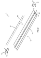
FIG. 1 is a schematic assembled view of a light bar in accordance with a first embodiment of the present invention; -
FIG. 2 is a schematic exploded view of the light bar ofFIG. 1 ; -
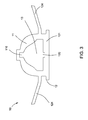
FIG. 3 is an enlarged view of an end portion of a tube ofFIG. 2 ; -
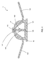
FIG. 4 is a cross-sectional view of the light bar ofFIG. 1 taken along the line A-A; -
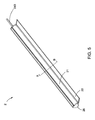
FIG. 5 is a schematic assembled view of a light bar in accordance with a second embodiment of the present invention; -
FIG. 6 is a schematic exploded view of the light bar ofFIG. 5 ; -
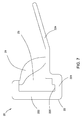
FIG. 7 is an enlarged view of an end portion of a tube ofFIG. 6 ; and -
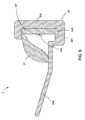
FIG. 8 is a cross-sectional view of the light bar ofFIG. 5 taken along the line B-B. - Embodiments of the present disclosure will be described hereinbelow with reference to the accompanying drawings. In the following description, well-known functions or constructions are not described in detail to avoid obscuring the disclosure in unnecessary detail.
- Unless defined otherwise, technical and scientific terms used herein have the same meaning as is commonly understood by one of ordinary skill in the art to which this disclosure belongs. The terms "first", "second", and the like, as used herein do not denote any order, quantity, or importance, but rather are used to distinguish one element from another. Also, the terms "a" and "an" do not denote a limitation of quantity, but rather denote the presence of at least one of the referenced items. The term "or" is meant to be inclusive and mean either or all of the listed items. The use of "including," "comprising" or "having" and variations thereof herein are meant to encompass the items listed thereafter and equivalents thereof as well as additional items.
-
FIGS. 1-4 illustrate schematic diagrams of a light bar in accordance with a first embodiment of the present invention. As shown inFIGS. 1 to 4 , the light bar in accordance with the first embodiment of the present invention includes anoptical component 11, ahousing 12 for reflecting light and asubstrate assembly 14. Theoptical component 11 and thehousing 12 extend longitudinally, and theoptical component 11 and thehousing 12 together form atube 10 with acavity 13. Thesubstrate assembly 14 is held in thecavity 13 of thetube 10 and comprises asubstrate 141 and a plurality ofLED light sources 142 mounted on thesubstrate 141. Light emitted from the plurality ofLED light sources 142 can be irradiated to at least one predetermined area perpendicular to thesubstrate 141 after passing through theoptical component 11. - The light bar 1 of the first embodiment is simple in structure and easy to assemble and has lower manufacturing cost. Furthermore, the light bar 1 can adopt multiple low power
LED light sources 142, thereby further reducing product cost. - The
optical component 11 may be refractive or act as a lens, or theoptical component 11 may be simply transmissive or translucent. Theoptical component 11 may be comprised of transparent or translucent polycarbonate, for example, or any other thermoplastic material which is transparent or translucent in operation, and which may be capable of being extruded or injection molded. - The
housing 12 may be an opaque or diffusive component which generally blocks the transmission of light. In one embodiment, thehousing 12 may be made from a reflective material. In another embodiment, thehousing 12 may also be made from a light-transmitting material which is covered by a layer of light-blocking material. For example, thehousing 12 may made from a transparent material covered with a layer of opaque material. Thehousing 12 may also be comprised of a polycarbonate material, which comprises additives that make it opaque or diffusive. Alternatively, the opaque or diffusive component acting as thehousing 12 may comprise other thermoplastic materials which do not pass light. Generally, thehousing 12 may also be capable of being extruded or injection molded. - In a preferable embodiment, the
optical component 11 and thehousing 12 may be made of suitably compatible thermoplastics, so theoptical component 11 and thehousing 12 may be made by a co-injection process or a co-extrusion process. By this way, theoptical component 11 and thehousing 12 are integrated together to form thetube 10 with thecavity 13. For example, theoptical component 11 and thehousing 12 are both made of polycarbonate, one is transparent or translucent, and the other is made to not be transparent or translucent, which may facilitate fabrication by a co-injection process or a co-extrusion process. Alternatively, theoptical component 11 and thehousing 12 can also be made of different kinds of thermoplastic materials. - With reference to
FIGS. 2-4 , thehousing 12 comprises amounting wall 121 substantially extending longitudinally. Themounting wall 121 of thehousing 12 is configured to be mounted onto a mullion of a display cabinet (not shown) so that the light bar 1 is fixed onto the mullion of the display cabinet. Thesubstrate assembly 14 is slidably and perpendicularly mounted in themounting wall 121 of thehousing 12 so as to distribute the light emitted from the plurality ofLED light sources 142 wider and easier. - The
substrate 141 has the shape of a slab. The slab-shapedsubstrate 141 has opposite two sides. In this embodiment, thesubstrate 141 is for example a printed circuit board (PCB). Certainly, thesubstrate 141 of the present invention should be not limited to the PCB. - Referring to
FIGS. 2 and4 , in the first embodiment of the present invention, the plurality of LEDlight sources 142 are mounted on opposite two sides of thesubstrate 141, and the light emitted from the plurality of LEDlight sources 142 can be irradiated to opposite two predetermined areas after passing through theoptical component 11. - In this embodiment, the light bar 1 has two halves which are symmetrical relative to the
substrate 141. So theoptical component 11 has two halves which are symmetrical relative to thesubstrate 141 and thehousing 12 also has two halves which are symmetrical relative to thesubstrate 141. In an embodiment, theoptical component 11 has a substantially dome-shaped cross-section. Each of the two halves of theoptical component 11 has different thickness. Theoptical component 11 can control the light emitted from the plurality of LEDlight sources 142 to shine a surface perpendicular to a substrate direction. The shape of the cross-section of theoptical component 11 can be properly changed according to user's requirements so that the light emitted from the plurality of LEDlight sources 142 can be irradiated to a desired display area. - As shown in
FIGS. 2 and3 , theoptical component 11 defines a firstlongitudinal channel 110 at a junction of the two halves thereof and thehousing 12 defines a secondlongitudinal channel 120 at a junction of the two halves thereof. Thesubstrate assembly 14 is slidably mounted between the firstlongitudinal channel 110 of theoptical component 11 and the secondlongitudinal channel 120 of thehousing 12 so that thesubstrate assembly 14 is held in thecavity 13 of thetube 10. - In an optional embodiment, the
housing 12 may further comprise a pair ofanti-dazzle wings 124 extending from opposite two lateral sides of the mountingwall 121 beyond theoptical component 11. The pair ofwings 124 can block light from theoptical component 11 to enter eyes of the user who is on the side of thehousing 12, which brings the user better visual effects. - With reference to
FIG. 3 , the light bar 1 further comprises a pair ofend caps 16 attached to ends of thetube 10 for sealing thecavity 13. One of the pair ofend caps 16 defines a hole (not shown) therein and thesubstrate assembly 14 further comprises awire harness 143 connecting with thesubstrate 141. Thewire harness 143 extends out of thetube 10 through the hole of theend cap 16 for connecting to an external controlling circuit. Theend cap 16 has a matching structure with thetube 10 so that the light bar 1 has a uniform appearance. - In assembly, the plurality of LED
light sources 142 are first mounted on thesubstrate 141 to form thesubstrate assembly 14. Then thesubstrate 141 with the plurality of LEDlight sources 142, i.e. thesubstrate assembly 14 is inserted to thecavity 13 of thetube 10 and slidably held between the firstlongitudinal channel 110 of theoptical component 11 and the secondlongitudinal channel 120 of thehousing 12. Finally, the pair ofend caps 16 are attached to the ends of thetube 10. The assembly of the light bar 1 is easily finished. -
FIGS. 5-8 illustrate schematic diagrams of a light bar in accordance with a second embodiment of the present invention. Similar to the light bar 1 of the first embodiment, as shown inFIGS. 5 to 8 , thelight bar 2 in accordance with the second embodiment also includes anoptical component 21, ahousing 22 for reflecting light and asubstrate assembly 24. Theoptical component 21 and thehousing 22 together form atube 20 with acavity 23. Thesubstrate assembly 24 is held in thecavity 23 of thetube 20 and comprises asubstrate 241, a plurality of LEDlight sources 242 mounted on thesubstrate 241, and awire harness 243 connecting with thesubstrate 241. In a preferable embodiment, theoptical component 21 and thehousing 22 are integrated together to form thetube 20 with thecavity 23 by a co-injection process or a co-extrusion process. - The
optical component 21 has different thickness. Theoptical component 21 can control the light emitted from the plurality of LEDlight sources 242 to shine a surface perpendicular to a substrate direction. The shape of the cross-section of theoptical component 21 can be properly changed according to user's requirements so that the light emitted from the plurality of LEDlight sources 242 can be irradiated to a desired display area. - Different from the light bar 1 of the first embodiment, the
light bar 2 of the second embodiment has substantially only one half of the light bar 1 of the first embodiment. Referring toFIGS. 6 and8 , in thelight bar 2 of the second embodiment, the plurality of LEDlight sources 242 are mounted on only one side of thesubstrate 241, and the light emitted from the plurality of LEDlight sources 242 is irradiated to a predetermined area after passing through theoptical component 21. - With reference to
FIGS. 6-8 , thehousing 22 comprises a mountingwall 221 substantially extending longitudinally and avertical wall 222 substantially extending vertically from one lateral side of the mountingwall 221. Thesubstrate assembly 24 is installed immediately adjacent to thevertical wall 222 of thehousing 22, so thesubstrate assembly 24 is perpendicular to the mountingwall 221 of thehousing 22. - As shown in
FIGS. 6-8 , thehousing 22 defines alongitudinal channel 220 at a junction of thevertical wall 222 and the mountingwall 221. Thesubstrate assembly 24 is slidably mounted in thelongitudinal channel 220 of thehousing 22 so that thesubstrate assembly 24 is held in thecavity 23 of thetube 20. - In an optional embodiment, the
housing 22 further comprises ananti-dazzle wing 224 extending from an opposite lateral side of the mountingwall 221 beyond theoptical component 21. Thewing 224 can block light from theoptical component 21 to enter eyes of the user who is on the side of thehousing 22, which brings the user better visual effects. - With reference to
FIG. 6 , thelight bar 2 further comprises a pair ofend caps 26 attached to ends of thetube 20 for sealing thecavity 23. One of the pair ofend caps 26 defines a hole (not shown) therein and thewire harness 243 connecting with thesubstrate 241 extends out of thetube 20 through the hole of theend cap 26. Theend cap 26 has a matching structure with thetube 20 so that thelight bar 2 has a uniform appearance. - In assembly, the plurality of LED
light sources 242 are first mounted on thesubstrate 241 to form thesubstrate assembly 24. Then thesubstrate 241 with the plurality of LEDlight sources 242, i.e. thesubstrate assembly 24 is inserted slidably into thelongitudinal channel 220 of thehousing 22 and is held in thecavity 23 of thetube 20. Finally, the pair ofend caps 26 are attached to the ends of thetube 20. The assembly of thelight bar 2 is easily finished. - The light bars 1 and 2 of the present invention are simple in structure and easy to assemble and has lower manufacturing cost. Furthermore, the light bars 1 and 2 can adopt multiple low power
LED light sources - The
light bar 1, 2 of the present invention can be applied to a refrigeration display (not shown). The refrigeration display comprises a plurality of shelves for holding product and at least one mullion having a mounting surface. The vertically extendinglight bar 1, 2 of the present invention can be positioned within the interior of the refrigeration display behind the at least one mullion and forward of the shelves. Thesubstrate light bar 1, 2 is perpendicular to the mounting surface of the at least one mullion. The light emitted from the plurality of LEDlight sources optical component light bar 1, 2. - The light bar 1 of the first embodiment and the
light bar 2 of the second embodiment can be used in different cases. When it is required that the light is irradiated to a single direction, thelight bar 2 of the second embodiment can be adopted. When it is required that the light is irradiated to opposite two directions, the light bar 1 of the first embodiment can be adopted. Certainly, when the light is not only required to be irradiated to a single direction, but also is required to be irradiated to opposite two directions, thelight bar 2 of the second embodiment and the light bar 1 of the first embodiment can be adopted. - For example, in the case that the at least one mullion of the refrigeration display comprises a central mullion, the refrigeration display can use the light bar 1 of the first embodiment. The light bar 1 of the first embodiment is positioned behind the central mullion and forward of the shelves. When the refrigeration display is in operation, the light emitted from the plurality of LED
light sources 142 on opposite two sides of thesubstrate 141 of the light bar 1 can be irradiated to the shelves on two lateral sides of the central mullion. - In the case that the at least one mullion of the refrigeration display comprises a side mullion, the refrigeration display can use the
light bar 2 of the second embodiment. Thelight bar 2 of the second embodiment is positioned behind the side mullion and forward of the shelves. When the refrigeration display is in operation, the light emitted from the plurality of LEDlight sources 242 on one side of thesubstrate 241 facing thecavity 23 of thelight bar 2 can be irradiated to the shelves on one lateral side of the side mullion. - When the refrigeration display is larger and comprises both the side mullion and the central mullion, such the refrigeration display can adopt both the light bar 1 of the first embodiment and the
light bar 2 of the second embodiment. - The
light bar 1, 2 of the present invention can distribute the light to a wider display area. Moreover, thelight bar 1, 2 of the present invention has a simpler structure and low cost, and is easy to assemble. Thelight bar 1, 2 of the present invention can widely applied to display cabinets of commercial establishments and has a better market prospect. - While the disclosure has been illustrated and described in typical embodiments, it is not intended to be limited to the details shown, since various modifications and substitutions can be made without departing in any way from the spirit of the present disclosure. As such, further modifications and equivalents of the disclosure herein disclosed may occur to persons skilled in the art using no more than routine experimentation, and all such modifications and equivalents are believed to be within the spirit and scope of the disclosure as defined by the following claims.
- Various aspects and embodiments of the present invention are defined by the following numbered clauses:
- 1. A refrigeration display, comprising:
- a plurality of shelves for holding product;
- at least one mullion having a mounting surface; and
- a vertically extending light bar positioned within the interior of the refrigeration display behind the at least one mullion and forward of the shelves, wherein the light bar comprises:
- an optical component;
- a housing for reflecting light, wherein the optical component and the housing together form a tube with a cavity; and
- a substrate assembly slidably held in the cavity and comprising:
- a substrate perpendicular to the mounting surface of the at least one mullion; and
- a plurality of LED light sources mounted on at least one side of the substrate, wherein light emitted from the plurality of LED light sources is irradiated to the shelves after passing through the optical component.
- 2. The refrigeration display of clause 1, wherein the at least one mullion comprises a central mullion, the light bar has two halves which are symmetrical relative to the substrate and the plurality of LED light sources are mounted on opposite two sides of the substrate, light emitted from the plurality of LED light sources being irradiated to the shelves on two lateral sides of the central mullion.
- 3. The refrigeration display of
clause 1 or 2, wherein the at least one mullion comprises a side mullion, the substrate is mounted immediately adjacent to a wall of the housing perpendicular to the side mullion and the plurality of LED light sources are mounted on one side of the substrate facing the cavity, light emitted from the plurality of LED light sources being irradiated to the shelves on one lateral side of the side mullion.
Claims (15)
- A light bar (1), comprising:an optical component (11);a housing (12) for reflecting light, wherein the optical component (11) and the housing (12) together form a tube (10) with a cavity (13); anda substrate assembly (14) held in the cavity (13) and comprising:a substrate (141); anda plurality of LED light sources (142) mounted on at least one side of the substrate (141), wherein light emitted from the plurality of LED light sources (142) is irradiated to at least one predetermined area perpendicular to the substrate (141) after passing through the optical component (11).
- The light bar of claim 1, wherein the optical component (11) and the housing (12) are integrated together by a co-extrusion or co-injection process.
- The light bar of claim 1 or 2, wherein the housing (12) comprises a mounting wall (121) substantially extending longitudinally for being mounted onto a mullion, and the substrate assembly (14) is slidably and perpendicularly mounted in the mounting wall (121) of the housing (12).
- The light bar of claim 3, wherein the substrate (141) has the shape of a slab.
- The light bar of claim 4, wherein the plurality of LED light sources (142) are mounted on opposite two sides of the substrate (141), and light emitted from the plurality of LED light sources (142) is irradiated to opposite two predetermined areas after passing through the optical component (11).
- The light bar of claim 5, wherein the light bar (1) has two halves which are symmetrical relative to the substrate (141).
- The light bar of claim 6, wherein the optical component (11) defines a first longitudinal channel (110) at a junction of two halves thereof and the housing (12) defines a second longitudinal channel (120) at a junction of two halves thereof, the substrate assembly (14) being slidably mounted between the first longitudinal channel (110) and the second longitudinal channel (120).
- The light bar of claim 6 or 7 wherein the housing (12) further comprises a pair of anti-dazzle wings (124) extending from opposite two lateral sides of the mounting wall (121) beyond the optical component (11).
- The light bar of claim 6, wherein the optical component (11) has a substantially dome-shaped cross-section.
- The light bar of any of claims 6 to 9, wherein each of two halves of the optical component (11) has different thickness.
- The light bar of claim 4, wherein the plurality of LED light sources (242) are mounted on one side of the substrate (241), and light emitted from the plurality of LED light sources (242) is irradiated to a predetermined area after passing through the optical component (21).
- The light bar of claim 11, wherein the housing further comprises a vertical wall (222) substantially extending vertically from one lateral side of a mounting wall (221), and the substrate assembly (24) is installed immediately adjacent to the vertical wall (222) of the housing (22).
- The light bar of claim 12, wherein the housing (22) defines a channel (220) at a junction of the vertical wall (222) and the mounting wall (221), the substrate assembly (24) being slidably mounted in the channel (220).
- The light bar of claim 12 or 13, wherein the housing (221) further comprises an anti-dazzle wing (224) extending from an opposite lateral side of the mounting wall (221) beyond the optical component (21) and wherein the optical component (21) has different thickness.
- The light bar of any preceding claim, further comprising a pair of end caps (16) attached to ends (10) of the tube for sealing the cavity (13), wherein one of the pair of end caps (16) defines a hole therein and the substrate assembly (14) further comprises a wire harness (143) connecting with the substrate (141), the wire harness (143) extending out of the tube (10) through the hole.
Applications Claiming Priority (1)
| Application Number | Priority Date | Filing Date | Title |
|---|---|---|---|
| CN201420673204.7U CN204345391U (en) | 2014-11-12 | 2014-11-12 | Lamp bar and refrigerated display cabinet |
Publications (2)
| Publication Number | Publication Date |
|---|---|
| EP3021037A1 true EP3021037A1 (en) | 2016-05-18 |
| EP3021037B1 EP3021037B1 (en) | 2018-10-17 |
Family
ID=53228659
Family Applications (1)
| Application Number | Title | Priority Date | Filing Date |
|---|---|---|---|
| EP15193051.8A Active EP3021037B1 (en) | 2014-11-12 | 2015-11-04 | Light bar |
Country Status (5)
| Country | Link |
|---|---|
| US (1) | US10001248B2 (en) |
| EP (1) | EP3021037B1 (en) |
| CN (1) | CN204345391U (en) |
| BR (1) | BR102015028345A2 (en) |
| MX (1) | MX359023B (en) |
Cited By (4)
| Publication number | Priority date | Publication date | Assignee | Title |
|---|---|---|---|---|
| CN105965904A (en) * | 2016-05-26 | 2016-09-28 | 中山市百事顺业塑料电器有限公司 | Production method of light guide decorative lamp strip |
| WO2018095853A1 (en) * | 2016-11-23 | 2018-05-31 | Philips Lighting Holding B.V. | Lighting strip and kit |
| WO2021122335A1 (en) | 2019-12-18 | 2021-06-24 | Franke Kaffeemaschinen Ag | Beverage maker having an outlet device |
| US11511659B2 (en) | 2021-03-18 | 2022-11-29 | Ford Global Technologies, Llc | Detachable lighting assembly for a vehicle |
Families Citing this family (9)
| Publication number | Priority date | Publication date | Assignee | Title |
|---|---|---|---|---|
| US9927092B2 (en) * | 2014-10-31 | 2018-03-27 | Itc Incorporated | LED linear light assembly with reflectance members |
| USD793604S1 (en) * | 2015-10-16 | 2017-08-01 | Anthony Whitter | Lighting panel |
| CN107518702B (en) * | 2016-06-22 | 2024-04-05 | 赛尔富电子有限公司 | LED bar lamp and exhibition cabinet |
| USD846323S1 (en) * | 2017-09-22 | 2019-04-23 | B-O-F Corporation | Divider member for product display shelf |
| CN107816667B (en) * | 2017-11-28 | 2024-04-16 | 赛尔富电子有限公司 | Light distribution system for refrigerator |
| US11002436B2 (en) * | 2018-04-30 | 2021-05-11 | L.J. Star, Incorporated | Winged light |
| CN110400518A (en) * | 2019-07-19 | 2019-11-01 | 江苏毅昌科技有限公司 | A kind of lamp bar |
| CN110848581A (en) * | 2019-11-08 | 2020-02-28 | 天津大学 | Integrated light-emitting source structure with adjustable irradiation range |
| CN213656513U (en) * | 2020-10-16 | 2021-07-09 | 漳州立达信光电子科技有限公司 | Lamp panel lamp |
Citations (5)
| Publication number | Priority date | Publication date | Assignee | Title |
|---|---|---|---|---|
| EP2233831A1 (en) * | 2007-12-27 | 2010-09-29 | Nichia Corporation | Lighting device, lighting unit, and support |
| WO2011019753A1 (en) * | 2009-08-13 | 2011-02-17 | Intematix Corporation | Led-based lamps |
| US20110084627A1 (en) * | 2009-10-13 | 2011-04-14 | Sloanled, Inc. | Shelf Lighting Device And Method |
| US20120170258A1 (en) * | 2011-01-05 | 2012-07-05 | Itc Incorporated | Lighting assembly |
| DE102011106252A1 (en) * | 2011-07-01 | 2013-01-03 | Siteco Beleuchtungstechnik Gmbh | Luminaire with potting compound |
Family Cites Families (7)
| Publication number | Priority date | Publication date | Assignee | Title |
|---|---|---|---|---|
| US7559672B1 (en) * | 2007-06-01 | 2009-07-14 | Inteled Corporation | Linear illumination lens with Fresnel facets |
| MX2008008558A (en) | 2007-06-29 | 2009-03-04 | Abl Ip Holding Llc | Led lighting assemblies for display cases. |
| WO2009052172A2 (en) * | 2007-10-15 | 2009-04-23 | Hussmann Corporation | Led lighting assembly with leds having different viewing angles |
| US7934701B2 (en) | 2008-07-01 | 2011-05-03 | Kay Ronald J | Safety handrail apparatus and manufacturing methods |
| US9057493B2 (en) * | 2010-03-26 | 2015-06-16 | Ilumisys, Inc. | LED light tube with dual sided light distribution |
| US9169977B2 (en) * | 2013-06-28 | 2015-10-27 | Cree, Inc. | LED lamp |
| US9441816B2 (en) * | 2013-10-28 | 2016-09-13 | Philips Lighting Holding B.V. | Lighting arrangement having a resilient element |
-
2014
- 2014-11-12 CN CN201420673204.7U patent/CN204345391U/en not_active Expired - Fee Related
-
2015
- 2015-11-04 EP EP15193051.8A patent/EP3021037B1/en active Active
- 2015-11-04 US US14/932,290 patent/US10001248B2/en not_active Expired - Fee Related
- 2015-11-11 BR BR102015028345A patent/BR102015028345A2/en not_active Application Discontinuation
- 2015-11-11 MX MX2015015629A patent/MX359023B/en active IP Right Grant
Patent Citations (5)
| Publication number | Priority date | Publication date | Assignee | Title |
|---|---|---|---|---|
| EP2233831A1 (en) * | 2007-12-27 | 2010-09-29 | Nichia Corporation | Lighting device, lighting unit, and support |
| WO2011019753A1 (en) * | 2009-08-13 | 2011-02-17 | Intematix Corporation | Led-based lamps |
| US20110084627A1 (en) * | 2009-10-13 | 2011-04-14 | Sloanled, Inc. | Shelf Lighting Device And Method |
| US20120170258A1 (en) * | 2011-01-05 | 2012-07-05 | Itc Incorporated | Lighting assembly |
| DE102011106252A1 (en) * | 2011-07-01 | 2013-01-03 | Siteco Beleuchtungstechnik Gmbh | Luminaire with potting compound |
Cited By (7)
| Publication number | Priority date | Publication date | Assignee | Title |
|---|---|---|---|---|
| CN105965904A (en) * | 2016-05-26 | 2016-09-28 | 中山市百事顺业塑料电器有限公司 | Production method of light guide decorative lamp strip |
| WO2018095853A1 (en) * | 2016-11-23 | 2018-05-31 | Philips Lighting Holding B.V. | Lighting strip and kit |
| US10584835B2 (en) | 2016-11-23 | 2020-03-10 | Signify Holding B.V. | Lighting strip and kit |
| WO2021122335A1 (en) | 2019-12-18 | 2021-06-24 | Franke Kaffeemaschinen Ag | Beverage maker having an outlet device |
| CN114828704A (en) * | 2019-12-18 | 2022-07-29 | 弗兰卡凯菲马斯池因股份公司 | Beverage preparation device with output device |
| CN114828704B (en) * | 2019-12-18 | 2023-12-01 | 弗兰卡凯菲马斯池因股份公司 | Beverage preparation device with output device |
| US11511659B2 (en) | 2021-03-18 | 2022-11-29 | Ford Global Technologies, Llc | Detachable lighting assembly for a vehicle |
Also Published As
| Publication number | Publication date |
|---|---|
| MX359023B (en) | 2018-09-11 |
| EP3021037B1 (en) | 2018-10-17 |
| US20160131311A1 (en) | 2016-05-12 |
| US10001248B2 (en) | 2018-06-19 |
| BR102015028345A2 (en) | 2016-05-24 |
| MX2015015629A (en) | 2016-08-16 |
| CN204345391U (en) | 2015-05-20 |
Similar Documents
| Publication | Publication Date | Title |
|---|---|---|
| US10001248B2 (en) | Light bar | |
| EP2480820B1 (en) | Shelf lighting device and method | |
| US20110058357A1 (en) | Led lighting assembly with leds having different viewing angles | |
| US20060265919A1 (en) | Transparent light-conducting module | |
| CN102656404A (en) | Refractive optics to provide uniform illumination in a display case | |
| US9612006B2 (en) | Table with integrated lighting | |
| US9703263B2 (en) | Floor clock having enhanced infinity mirror | |
| CN108930954A (en) | Illuminate vehicle assembly and means of illumination | |
| US9443453B2 (en) | Illuminated display board having an angled light source | |
| US9153150B2 (en) | Lighting assembly having enhanced visual appearance | |
| WO2006081762A1 (en) | A transparent illuminating module | |
| KR200457643Y1 (en) | A display assembly with sub-display | |
| CN103017472B (en) | Lighting assembly used for refrigerator | |
| CN106402723B (en) | A kind of LED lamp | |
| KR101439964B1 (en) | Sign frame | |
| CN106931352B (en) | Exhibition cabinet | |
| JP3163988U (en) | lighting equipment | |
| KR200475842Y1 (en) | Signboard using LED | |
| JP2016081769A (en) | Light guide member, light-emitting body and signboard | |
| CN104567260A (en) | Refrigerator | |
| CN218273908U (en) | Door body assembly and refrigerator | |
| CN209893799U (en) | Lighting assembly of refrigerator and refrigerator | |
| CN210772964U (en) | Refrigeration device | |
| US20140301072A1 (en) | Lighting fixtures having illuminated ornaments and methods for providing illumination | |
| KR101302406B1 (en) | A lighting structure for showcase refrigerator |
Legal Events
| Date | Code | Title | Description |
|---|---|---|---|
| PUAI | Public reference made under article 153(3) epc to a published international application that has entered the european phase |
Free format text: ORIGINAL CODE: 0009012 |
|
| AK | Designated contracting states |
Kind code of ref document: A1 Designated state(s): AL AT BE BG CH CY CZ DE DK EE ES FI FR GB GR HR HU IE IS IT LI LT LU LV MC MK MT NL NO PL PT RO RS SE SI SK SM TR |
|
| AX | Request for extension of the european patent |
Extension state: BA ME |
|
| STAA | Information on the status of an ep patent application or granted ep patent |
Free format text: STATUS: REQUEST FOR EXAMINATION WAS MADE |
|
| 17P | Request for examination filed |
Effective date: 20161118 |
|
| RBV | Designated contracting states (corrected) |
Designated state(s): AL AT BE BG CH CY CZ DE DK EE ES FI FR GB GR HR HU IE IS IT LI LT LU LV MC MK MT NL NO PL PT RO RS SE SI SK SM TR |
|
| GRAP | Despatch of communication of intention to grant a patent |
Free format text: ORIGINAL CODE: EPIDOSNIGR1 |
|
| STAA | Information on the status of an ep patent application or granted ep patent |
Free format text: STATUS: GRANT OF PATENT IS INTENDED |
|
| RIC1 | Information provided on ipc code assigned before grant |
Ipc: F21Y 115/10 20160101ALN20180517BHEP Ipc: F21S 4/28 20160101AFI20180517BHEP |
|
| RIC1 | Information provided on ipc code assigned before grant |
Ipc: F21S 4/28 20160101AFI20180529BHEP Ipc: F21Y 115/10 20160101ALN20180529BHEP |
|
| INTG | Intention to grant announced |
Effective date: 20180614 |
|
| GRAS | Grant fee paid |
Free format text: ORIGINAL CODE: EPIDOSNIGR3 |
|
| GRAA | (expected) grant |
Free format text: ORIGINAL CODE: 0009210 |
|
| STAA | Information on the status of an ep patent application or granted ep patent |
Free format text: STATUS: THE PATENT HAS BEEN GRANTED |
|
| AK | Designated contracting states |
Kind code of ref document: B1 Designated state(s): AL AT BE BG CH CY CZ DE DK EE ES FI FR GB GR HR HU IE IS IT LI LT LU LV MC MK MT NL NO PL PT RO RS SE SI SK SM TR |
|
| REG | Reference to a national code |
Ref country code: GB Ref legal event code: FG4D |
|
| REG | Reference to a national code |
Ref country code: CH Ref legal event code: EP |
|
| REG | Reference to a national code |
Ref country code: IE Ref legal event code: FG4D |
|
| REG | Reference to a national code |
Ref country code: DE Ref legal event code: R096 Ref document number: 602015018202 Country of ref document: DE Ref country code: AT Ref legal event code: REF Ref document number: 1054473 Country of ref document: AT Kind code of ref document: T Effective date: 20181115 |
|
| REG | Reference to a national code |
Ref country code: NL Ref legal event code: FP |
|
| REG | Reference to a national code |
Ref country code: LT Ref legal event code: MG4D |
|
| REG | Reference to a national code |
Ref country code: AT Ref legal event code: MK05 Ref document number: 1054473 Country of ref document: AT Kind code of ref document: T Effective date: 20181017 |
|
| PG25 | Lapsed in a contracting state [announced via postgrant information from national office to epo] |
Ref country code: LV Free format text: LAPSE BECAUSE OF FAILURE TO SUBMIT A TRANSLATION OF THE DESCRIPTION OR TO PAY THE FEE WITHIN THE PRESCRIBED TIME-LIMIT Effective date: 20181017 Ref country code: AT Free format text: LAPSE BECAUSE OF FAILURE TO SUBMIT A TRANSLATION OF THE DESCRIPTION OR TO PAY THE FEE WITHIN THE PRESCRIBED TIME-LIMIT Effective date: 20181017 Ref country code: HR Free format text: LAPSE BECAUSE OF FAILURE TO SUBMIT A TRANSLATION OF THE DESCRIPTION OR TO PAY THE FEE WITHIN THE PRESCRIBED TIME-LIMIT Effective date: 20181017 Ref country code: LT Free format text: LAPSE BECAUSE OF FAILURE TO SUBMIT A TRANSLATION OF THE DESCRIPTION OR TO PAY THE FEE WITHIN THE PRESCRIBED TIME-LIMIT Effective date: 20181017 Ref country code: PL Free format text: LAPSE BECAUSE OF FAILURE TO SUBMIT A TRANSLATION OF THE DESCRIPTION OR TO PAY THE FEE WITHIN THE PRESCRIBED TIME-LIMIT Effective date: 20181017 Ref country code: NO Free format text: LAPSE BECAUSE OF FAILURE TO SUBMIT A TRANSLATION OF THE DESCRIPTION OR TO PAY THE FEE WITHIN THE PRESCRIBED TIME-LIMIT Effective date: 20190117 Ref country code: BG Free format text: LAPSE BECAUSE OF FAILURE TO SUBMIT A TRANSLATION OF THE DESCRIPTION OR TO PAY THE FEE WITHIN THE PRESCRIBED TIME-LIMIT Effective date: 20190117 Ref country code: ES Free format text: LAPSE BECAUSE OF FAILURE TO SUBMIT A TRANSLATION OF THE DESCRIPTION OR TO PAY THE FEE WITHIN THE PRESCRIBED TIME-LIMIT Effective date: 20181017 Ref country code: IS Free format text: LAPSE BECAUSE OF FAILURE TO SUBMIT A TRANSLATION OF THE DESCRIPTION OR TO PAY THE FEE WITHIN THE PRESCRIBED TIME-LIMIT Effective date: 20190217 Ref country code: FI Free format text: LAPSE BECAUSE OF FAILURE TO SUBMIT A TRANSLATION OF THE DESCRIPTION OR TO PAY THE FEE WITHIN THE PRESCRIBED TIME-LIMIT Effective date: 20181017 |
|
| PG25 | Lapsed in a contracting state [announced via postgrant information from national office to epo] |
Ref country code: RS Free format text: LAPSE BECAUSE OF FAILURE TO SUBMIT A TRANSLATION OF THE DESCRIPTION OR TO PAY THE FEE WITHIN THE PRESCRIBED TIME-LIMIT Effective date: 20181017 Ref country code: GR Free format text: LAPSE BECAUSE OF FAILURE TO SUBMIT A TRANSLATION OF THE DESCRIPTION OR TO PAY THE FEE WITHIN THE PRESCRIBED TIME-LIMIT Effective date: 20190118 Ref country code: SE Free format text: LAPSE BECAUSE OF FAILURE TO SUBMIT A TRANSLATION OF THE DESCRIPTION OR TO PAY THE FEE WITHIN THE PRESCRIBED TIME-LIMIT Effective date: 20181017 Ref country code: AL Free format text: LAPSE BECAUSE OF FAILURE TO SUBMIT A TRANSLATION OF THE DESCRIPTION OR TO PAY THE FEE WITHIN THE PRESCRIBED TIME-LIMIT Effective date: 20181017 Ref country code: PT Free format text: LAPSE BECAUSE OF FAILURE TO SUBMIT A TRANSLATION OF THE DESCRIPTION OR TO PAY THE FEE WITHIN THE PRESCRIBED TIME-LIMIT Effective date: 20190217 |
|
| REG | Reference to a national code |
Ref country code: CH Ref legal event code: PL |
|
| REG | Reference to a national code |
Ref country code: DE Ref legal event code: R097 Ref document number: 602015018202 Country of ref document: DE |
|
| PG25 | Lapsed in a contracting state [announced via postgrant information from national office to epo] |
Ref country code: DK Free format text: LAPSE BECAUSE OF FAILURE TO SUBMIT A TRANSLATION OF THE DESCRIPTION OR TO PAY THE FEE WITHIN THE PRESCRIBED TIME-LIMIT Effective date: 20181017 Ref country code: LU Free format text: LAPSE BECAUSE OF NON-PAYMENT OF DUE FEES Effective date: 20181104 |
|
| REG | Reference to a national code |
Ref country code: BE Ref legal event code: MM Effective date: 20181130 |
|
| REG | Reference to a national code |
Ref country code: IE Ref legal event code: MM4A |
|
| PLBE | No opposition filed within time limit |
Free format text: ORIGINAL CODE: 0009261 |
|
| STAA | Information on the status of an ep patent application or granted ep patent |
Free format text: STATUS: NO OPPOSITION FILED WITHIN TIME LIMIT |
|
| RAP2 | Party data changed (patent owner data changed or rights of a patent transferred) |
Owner name: CURRENT LIGHTING SOLUTIONS, LLC |
|
| PG25 | Lapsed in a contracting state [announced via postgrant information from national office to epo] |
Ref country code: CH Free format text: LAPSE BECAUSE OF NON-PAYMENT OF DUE FEES Effective date: 20181130 Ref country code: RO Free format text: LAPSE BECAUSE OF FAILURE TO SUBMIT A TRANSLATION OF THE DESCRIPTION OR TO PAY THE FEE WITHIN THE PRESCRIBED TIME-LIMIT Effective date: 20181017 Ref country code: SK Free format text: LAPSE BECAUSE OF FAILURE TO SUBMIT A TRANSLATION OF THE DESCRIPTION OR TO PAY THE FEE WITHIN THE PRESCRIBED TIME-LIMIT Effective date: 20181017 Ref country code: LI Free format text: LAPSE BECAUSE OF NON-PAYMENT OF DUE FEES Effective date: 20181130 Ref country code: EE Free format text: LAPSE BECAUSE OF FAILURE TO SUBMIT A TRANSLATION OF THE DESCRIPTION OR TO PAY THE FEE WITHIN THE PRESCRIBED TIME-LIMIT Effective date: 20181017 Ref country code: MC Free format text: LAPSE BECAUSE OF FAILURE TO SUBMIT A TRANSLATION OF THE DESCRIPTION OR TO PAY THE FEE WITHIN THE PRESCRIBED TIME-LIMIT Effective date: 20181017 Ref country code: SM Free format text: LAPSE BECAUSE OF FAILURE TO SUBMIT A TRANSLATION OF THE DESCRIPTION OR TO PAY THE FEE WITHIN THE PRESCRIBED TIME-LIMIT Effective date: 20181017 |
|
| 26N | No opposition filed |
Effective date: 20190718 |
|
| PG25 | Lapsed in a contracting state [announced via postgrant information from national office to epo] |
Ref country code: SI Free format text: LAPSE BECAUSE OF FAILURE TO SUBMIT A TRANSLATION OF THE DESCRIPTION OR TO PAY THE FEE WITHIN THE PRESCRIBED TIME-LIMIT Effective date: 20181017 Ref country code: IE Free format text: LAPSE BECAUSE OF NON-PAYMENT OF DUE FEES Effective date: 20181104 |
|
| PG25 | Lapsed in a contracting state [announced via postgrant information from national office to epo] |
Ref country code: BE Free format text: LAPSE BECAUSE OF NON-PAYMENT OF DUE FEES Effective date: 20181130 |
|
| PG25 | Lapsed in a contracting state [announced via postgrant information from national office to epo] |
Ref country code: MT Free format text: LAPSE BECAUSE OF NON-PAYMENT OF DUE FEES Effective date: 20181104 |
|
| PG25 | Lapsed in a contracting state [announced via postgrant information from national office to epo] |
Ref country code: TR Free format text: LAPSE BECAUSE OF FAILURE TO SUBMIT A TRANSLATION OF THE DESCRIPTION OR TO PAY THE FEE WITHIN THE PRESCRIBED TIME-LIMIT Effective date: 20181017 |
|
| PG25 | Lapsed in a contracting state [announced via postgrant information from national office to epo] |
Ref country code: MK Free format text: LAPSE BECAUSE OF NON-PAYMENT OF DUE FEES Effective date: 20181017 Ref country code: CY Free format text: LAPSE BECAUSE OF FAILURE TO SUBMIT A TRANSLATION OF THE DESCRIPTION OR TO PAY THE FEE WITHIN THE PRESCRIBED TIME-LIMIT Effective date: 20181017 Ref country code: HU Free format text: LAPSE BECAUSE OF FAILURE TO SUBMIT A TRANSLATION OF THE DESCRIPTION OR TO PAY THE FEE WITHIN THE PRESCRIBED TIME-LIMIT; INVALID AB INITIO Effective date: 20151104 |
|
| REG | Reference to a national code |
Ref country code: NL Ref legal event code: HC Owner name: CURRENT LIGHTING SOLUTIONS, LLC; US Free format text: DETAILS ASSIGNMENT: CHANGE OF OWNER(S), CHANGE OF OWNER(S) NAME; FORMER OWNER NAME: GE LIGHTING SOLUTIONS, LLC Effective date: 20200911 |
|
| PGFP | Annual fee paid to national office [announced via postgrant information from national office to epo] |
Ref country code: NL Payment date: 20211020 Year of fee payment: 7 |
|
| PGFP | Annual fee paid to national office [announced via postgrant information from national office to epo] |
Ref country code: CZ Payment date: 20211026 Year of fee payment: 7 Ref country code: DE Payment date: 20211020 Year of fee payment: 7 |
|
| REG | Reference to a national code |
Ref country code: DE Ref legal event code: R119 Ref document number: 602015018202 Country of ref document: DE |
|
| P01 | Opt-out of the competence of the unified patent court (upc) registered |
Effective date: 20230518 |
|
| REG | Reference to a national code |
Ref country code: NL Ref legal event code: MM Effective date: 20221201 |
|
| PG25 | Lapsed in a contracting state [announced via postgrant information from national office to epo] |
Ref country code: CZ Free format text: LAPSE BECAUSE OF NON-PAYMENT OF DUE FEES Effective date: 20221104 |
|
| PG25 | Lapsed in a contracting state [announced via postgrant information from national office to epo] |
Ref country code: NL Free format text: LAPSE BECAUSE OF NON-PAYMENT OF DUE FEES Effective date: 20221201 |
|
| PG25 | Lapsed in a contracting state [announced via postgrant information from national office to epo] |
Ref country code: DE Free format text: LAPSE BECAUSE OF NON-PAYMENT OF DUE FEES Effective date: 20230601 |
|
| PGFP | Annual fee paid to national office [announced via postgrant information from national office to epo] |
Ref country code: GB Payment date: 20231019 Year of fee payment: 9 |
|
| PGFP | Annual fee paid to national office [announced via postgrant information from national office to epo] |
Ref country code: IT Payment date: 20231019 Year of fee payment: 9 Ref country code: FR Payment date: 20231019 Year of fee payment: 9 |