EP3021031A1 - Dip tube arrangement within a gas tank for liquefied or high pressure gases - Google Patents
Dip tube arrangement within a gas tank for liquefied or high pressure gases Download PDFInfo
- Publication number
- EP3021031A1 EP3021031A1 EP15193486.6A EP15193486A EP3021031A1 EP 3021031 A1 EP3021031 A1 EP 3021031A1 EP 15193486 A EP15193486 A EP 15193486A EP 3021031 A1 EP3021031 A1 EP 3021031A1
- Authority
- EP
- European Patent Office
- Prior art keywords
- pipe
- main body
- valve
- axial direction
- tank main
- Prior art date
- Legal status (The legal status is an assumption and is not a legal conclusion. Google has not performed a legal analysis and makes no representation as to the accuracy of the status listed.)
- Granted
Links
Images

Classifications
-
- F—MECHANICAL ENGINEERING; LIGHTING; HEATING; WEAPONS; BLASTING
- F17—STORING OR DISTRIBUTING GASES OR LIQUIDS
- F17C—VESSELS FOR CONTAINING OR STORING COMPRESSED, LIQUEFIED OR SOLIDIFIED GASES; FIXED-CAPACITY GAS-HOLDERS; FILLING VESSELS WITH, OR DISCHARGING FROM VESSELS, COMPRESSED, LIQUEFIED, OR SOLIDIFIED GASES
- F17C1/00—Pressure vessels, e.g. gas cylinder, gas tank, replaceable cartridge
- F17C1/005—Storage of gas or gaseous mixture at high pressure and at high density condition, e.g. in the single state phase
-
- F—MECHANICAL ENGINEERING; LIGHTING; HEATING; WEAPONS; BLASTING
- F17—STORING OR DISTRIBUTING GASES OR LIQUIDS
- F17C—VESSELS FOR CONTAINING OR STORING COMPRESSED, LIQUEFIED OR SOLIDIFIED GASES; FIXED-CAPACITY GAS-HOLDERS; FILLING VESSELS WITH, OR DISCHARGING FROM VESSELS, COMPRESSED, LIQUEFIED, OR SOLIDIFIED GASES
- F17C1/00—Pressure vessels, e.g. gas cylinder, gas tank, replaceable cartridge
-
- B—PERFORMING OPERATIONS; TRANSPORTING
- B60—VEHICLES IN GENERAL
- B60K—ARRANGEMENT OR MOUNTING OF PROPULSION UNITS OR OF TRANSMISSIONS IN VEHICLES; ARRANGEMENT OR MOUNTING OF PLURAL DIVERSE PRIME-MOVERS IN VEHICLES; AUXILIARY DRIVES FOR VEHICLES; INSTRUMENTATION OR DASHBOARDS FOR VEHICLES; ARRANGEMENTS IN CONNECTION WITH COOLING, AIR INTAKE, GAS EXHAUST OR FUEL SUPPLY OF PROPULSION UNITS IN VEHICLES
- B60K15/00—Arrangement in connection with fuel supply of combustion engines or other fuel consuming energy converters, e.g. fuel cells; Mounting or construction of fuel tanks
- B60K15/03—Fuel tanks
- B60K15/04—Tank inlets
-
- F—MECHANICAL ENGINEERING; LIGHTING; HEATING; WEAPONS; BLASTING
- F17—STORING OR DISTRIBUTING GASES OR LIQUIDS
- F17C—VESSELS FOR CONTAINING OR STORING COMPRESSED, LIQUEFIED OR SOLIDIFIED GASES; FIXED-CAPACITY GAS-HOLDERS; FILLING VESSELS WITH, OR DISCHARGING FROM VESSELS, COMPRESSED, LIQUEFIED, OR SOLIDIFIED GASES
- F17C13/00—Details of vessels or of the filling or discharging of vessels
- F17C13/02—Special adaptations of indicating, measuring, or monitoring equipment
- F17C13/026—Special adaptations of indicating, measuring, or monitoring equipment having the temperature as the parameter
-
- F—MECHANICAL ENGINEERING; LIGHTING; HEATING; WEAPONS; BLASTING
- F17—STORING OR DISTRIBUTING GASES OR LIQUIDS
- F17C—VESSELS FOR CONTAINING OR STORING COMPRESSED, LIQUEFIED OR SOLIDIFIED GASES; FIXED-CAPACITY GAS-HOLDERS; FILLING VESSELS WITH, OR DISCHARGING FROM VESSELS, COMPRESSED, LIQUEFIED, OR SOLIDIFIED GASES
- F17C13/00—Details of vessels or of the filling or discharging of vessels
- F17C13/04—Arrangement or mounting of valves
-
- F—MECHANICAL ENGINEERING; LIGHTING; HEATING; WEAPONS; BLASTING
- F17—STORING OR DISTRIBUTING GASES OR LIQUIDS
- F17C—VESSELS FOR CONTAINING OR STORING COMPRESSED, LIQUEFIED OR SOLIDIFIED GASES; FIXED-CAPACITY GAS-HOLDERS; FILLING VESSELS WITH, OR DISCHARGING FROM VESSELS, COMPRESSED, LIQUEFIED, OR SOLIDIFIED GASES
- F17C7/00—Methods or apparatus for discharging liquefied, solidified, or compressed gases from pressure vessels, not covered by another subclass
-
- F—MECHANICAL ENGINEERING; LIGHTING; HEATING; WEAPONS; BLASTING
- F17—STORING OR DISTRIBUTING GASES OR LIQUIDS
- F17C—VESSELS FOR CONTAINING OR STORING COMPRESSED, LIQUEFIED OR SOLIDIFIED GASES; FIXED-CAPACITY GAS-HOLDERS; FILLING VESSELS WITH, OR DISCHARGING FROM VESSELS, COMPRESSED, LIQUEFIED, OR SOLIDIFIED GASES
- F17C1/00—Pressure vessels, e.g. gas cylinder, gas tank, replaceable cartridge
- F17C1/16—Pressure vessels, e.g. gas cylinder, gas tank, replaceable cartridge constructed of plastics materials
-
- F—MECHANICAL ENGINEERING; LIGHTING; HEATING; WEAPONS; BLASTING
- F17—STORING OR DISTRIBUTING GASES OR LIQUIDS
- F17C—VESSELS FOR CONTAINING OR STORING COMPRESSED, LIQUEFIED OR SOLIDIFIED GASES; FIXED-CAPACITY GAS-HOLDERS; FILLING VESSELS WITH, OR DISCHARGING FROM VESSELS, COMPRESSED, LIQUEFIED, OR SOLIDIFIED GASES
- F17C2203/00—Vessel construction, in particular walls or details thereof
- F17C2203/06—Materials for walls or layers thereof; Properties or structures of walls or their materials
- F17C2203/0602—Wall structures; Special features thereof
- F17C2203/0604—Liners
-
- F—MECHANICAL ENGINEERING; LIGHTING; HEATING; WEAPONS; BLASTING
- F17—STORING OR DISTRIBUTING GASES OR LIQUIDS
- F17C—VESSELS FOR CONTAINING OR STORING COMPRESSED, LIQUEFIED OR SOLIDIFIED GASES; FIXED-CAPACITY GAS-HOLDERS; FILLING VESSELS WITH, OR DISCHARGING FROM VESSELS, COMPRESSED, LIQUEFIED, OR SOLIDIFIED GASES
- F17C2203/00—Vessel construction, in particular walls or details thereof
- F17C2203/06—Materials for walls or layers thereof; Properties or structures of walls or their materials
- F17C2203/0602—Wall structures; Special features thereof
- F17C2203/0612—Wall structures
- F17C2203/0614—Single wall
- F17C2203/0619—Single wall with two layers
-
- F—MECHANICAL ENGINEERING; LIGHTING; HEATING; WEAPONS; BLASTING
- F17—STORING OR DISTRIBUTING GASES OR LIQUIDS
- F17C—VESSELS FOR CONTAINING OR STORING COMPRESSED, LIQUEFIED OR SOLIDIFIED GASES; FIXED-CAPACITY GAS-HOLDERS; FILLING VESSELS WITH, OR DISCHARGING FROM VESSELS, COMPRESSED, LIQUEFIED, OR SOLIDIFIED GASES
- F17C2203/00—Vessel construction, in particular walls or details thereof
- F17C2203/06—Materials for walls or layers thereof; Properties or structures of walls or their materials
- F17C2203/0634—Materials for walls or layers thereof
- F17C2203/0658—Synthetics
- F17C2203/0663—Synthetics in form of fibers or filaments
- F17C2203/0673—Polymers
-
- F—MECHANICAL ENGINEERING; LIGHTING; HEATING; WEAPONS; BLASTING
- F17—STORING OR DISTRIBUTING GASES OR LIQUIDS
- F17C—VESSELS FOR CONTAINING OR STORING COMPRESSED, LIQUEFIED OR SOLIDIFIED GASES; FIXED-CAPACITY GAS-HOLDERS; FILLING VESSELS WITH, OR DISCHARGING FROM VESSELS, COMPRESSED, LIQUEFIED, OR SOLIDIFIED GASES
- F17C2205/00—Vessel construction, in particular mounting arrangements, attachments or identifications means
- F17C2205/01—Mounting arrangements
- F17C2205/0123—Mounting arrangements characterised by number of vessels
- F17C2205/013—Two or more vessels
- F17C2205/0134—Two or more vessels characterised by the presence of fluid connection between vessels
-
- F—MECHANICAL ENGINEERING; LIGHTING; HEATING; WEAPONS; BLASTING
- F17—STORING OR DISTRIBUTING GASES OR LIQUIDS
- F17C—VESSELS FOR CONTAINING OR STORING COMPRESSED, LIQUEFIED OR SOLIDIFIED GASES; FIXED-CAPACITY GAS-HOLDERS; FILLING VESSELS WITH, OR DISCHARGING FROM VESSELS, COMPRESSED, LIQUEFIED, OR SOLIDIFIED GASES
- F17C2205/00—Vessel construction, in particular mounting arrangements, attachments or identifications means
- F17C2205/03—Fluid connections, filters, valves, closure means or other attachments
- F17C2205/0302—Fittings, valves, filters, or components in connection with the gas storage device
- F17C2205/0305—Bosses, e.g. boss collars
-
- F—MECHANICAL ENGINEERING; LIGHTING; HEATING; WEAPONS; BLASTING
- F17—STORING OR DISTRIBUTING GASES OR LIQUIDS
- F17C—VESSELS FOR CONTAINING OR STORING COMPRESSED, LIQUEFIED OR SOLIDIFIED GASES; FIXED-CAPACITY GAS-HOLDERS; FILLING VESSELS WITH, OR DISCHARGING FROM VESSELS, COMPRESSED, LIQUEFIED, OR SOLIDIFIED GASES
- F17C2205/00—Vessel construction, in particular mounting arrangements, attachments or identifications means
- F17C2205/03—Fluid connections, filters, valves, closure means or other attachments
- F17C2205/0302—Fittings, valves, filters, or components in connection with the gas storage device
- F17C2205/0323—Valves
-
- F—MECHANICAL ENGINEERING; LIGHTING; HEATING; WEAPONS; BLASTING
- F17—STORING OR DISTRIBUTING GASES OR LIQUIDS
- F17C—VESSELS FOR CONTAINING OR STORING COMPRESSED, LIQUEFIED OR SOLIDIFIED GASES; FIXED-CAPACITY GAS-HOLDERS; FILLING VESSELS WITH, OR DISCHARGING FROM VESSELS, COMPRESSED, LIQUEFIED, OR SOLIDIFIED GASES
- F17C2221/00—Handled fluid, in particular type of fluid
- F17C2221/01—Pure fluids
- F17C2221/012—Hydrogen
-
- F—MECHANICAL ENGINEERING; LIGHTING; HEATING; WEAPONS; BLASTING
- F17—STORING OR DISTRIBUTING GASES OR LIQUIDS
- F17C—VESSELS FOR CONTAINING OR STORING COMPRESSED, LIQUEFIED OR SOLIDIFIED GASES; FIXED-CAPACITY GAS-HOLDERS; FILLING VESSELS WITH, OR DISCHARGING FROM VESSELS, COMPRESSED, LIQUEFIED, OR SOLIDIFIED GASES
- F17C2221/00—Handled fluid, in particular type of fluid
- F17C2221/03—Mixtures
- F17C2221/032—Hydrocarbons
- F17C2221/033—Methane, e.g. natural gas, CNG, LNG, GNL, GNC, PLNG
-
- F—MECHANICAL ENGINEERING; LIGHTING; HEATING; WEAPONS; BLASTING
- F17—STORING OR DISTRIBUTING GASES OR LIQUIDS
- F17C—VESSELS FOR CONTAINING OR STORING COMPRESSED, LIQUEFIED OR SOLIDIFIED GASES; FIXED-CAPACITY GAS-HOLDERS; FILLING VESSELS WITH, OR DISCHARGING FROM VESSELS, COMPRESSED, LIQUEFIED, OR SOLIDIFIED GASES
- F17C2221/00—Handled fluid, in particular type of fluid
- F17C2221/03—Mixtures
- F17C2221/032—Hydrocarbons
- F17C2221/035—Propane butane, e.g. LPG, GPL
-
- F—MECHANICAL ENGINEERING; LIGHTING; HEATING; WEAPONS; BLASTING
- F17—STORING OR DISTRIBUTING GASES OR LIQUIDS
- F17C—VESSELS FOR CONTAINING OR STORING COMPRESSED, LIQUEFIED OR SOLIDIFIED GASES; FIXED-CAPACITY GAS-HOLDERS; FILLING VESSELS WITH, OR DISCHARGING FROM VESSELS, COMPRESSED, LIQUEFIED, OR SOLIDIFIED GASES
- F17C2223/00—Handled fluid before transfer, i.e. state of fluid when stored in the vessel or before transfer from the vessel
- F17C2223/01—Handled fluid before transfer, i.e. state of fluid when stored in the vessel or before transfer from the vessel characterised by the phase
- F17C2223/0107—Single phase
- F17C2223/0123—Single phase gaseous, e.g. CNG, GNC
-
- F—MECHANICAL ENGINEERING; LIGHTING; HEATING; WEAPONS; BLASTING
- F17—STORING OR DISTRIBUTING GASES OR LIQUIDS
- F17C—VESSELS FOR CONTAINING OR STORING COMPRESSED, LIQUEFIED OR SOLIDIFIED GASES; FIXED-CAPACITY GAS-HOLDERS; FILLING VESSELS WITH, OR DISCHARGING FROM VESSELS, COMPRESSED, LIQUEFIED, OR SOLIDIFIED GASES
- F17C2223/00—Handled fluid before transfer, i.e. state of fluid when stored in the vessel or before transfer from the vessel
- F17C2223/01—Handled fluid before transfer, i.e. state of fluid when stored in the vessel or before transfer from the vessel characterised by the phase
- F17C2223/0146—Two-phase
- F17C2223/0153—Liquefied gas, e.g. LPG, GPL
- F17C2223/0161—Liquefied gas, e.g. LPG, GPL cryogenic, e.g. LNG, GNL, PLNG
-
- F—MECHANICAL ENGINEERING; LIGHTING; HEATING; WEAPONS; BLASTING
- F17—STORING OR DISTRIBUTING GASES OR LIQUIDS
- F17C—VESSELS FOR CONTAINING OR STORING COMPRESSED, LIQUEFIED OR SOLIDIFIED GASES; FIXED-CAPACITY GAS-HOLDERS; FILLING VESSELS WITH, OR DISCHARGING FROM VESSELS, COMPRESSED, LIQUEFIED, OR SOLIDIFIED GASES
- F17C2223/00—Handled fluid before transfer, i.e. state of fluid when stored in the vessel or before transfer from the vessel
- F17C2223/03—Handled fluid before transfer, i.e. state of fluid when stored in the vessel or before transfer from the vessel characterised by the pressure level
- F17C2223/033—Small pressure, e.g. for liquefied gas
-
- F—MECHANICAL ENGINEERING; LIGHTING; HEATING; WEAPONS; BLASTING
- F17—STORING OR DISTRIBUTING GASES OR LIQUIDS
- F17C—VESSELS FOR CONTAINING OR STORING COMPRESSED, LIQUEFIED OR SOLIDIFIED GASES; FIXED-CAPACITY GAS-HOLDERS; FILLING VESSELS WITH, OR DISCHARGING FROM VESSELS, COMPRESSED, LIQUEFIED, OR SOLIDIFIED GASES
- F17C2223/00—Handled fluid before transfer, i.e. state of fluid when stored in the vessel or before transfer from the vessel
- F17C2223/03—Handled fluid before transfer, i.e. state of fluid when stored in the vessel or before transfer from the vessel characterised by the pressure level
- F17C2223/035—High pressure (>10 bar)
-
- F—MECHANICAL ENGINEERING; LIGHTING; HEATING; WEAPONS; BLASTING
- F17—STORING OR DISTRIBUTING GASES OR LIQUIDS
- F17C—VESSELS FOR CONTAINING OR STORING COMPRESSED, LIQUEFIED OR SOLIDIFIED GASES; FIXED-CAPACITY GAS-HOLDERS; FILLING VESSELS WITH, OR DISCHARGING FROM VESSELS, COMPRESSED, LIQUEFIED, OR SOLIDIFIED GASES
- F17C2223/00—Handled fluid before transfer, i.e. state of fluid when stored in the vessel or before transfer from the vessel
- F17C2223/03—Handled fluid before transfer, i.e. state of fluid when stored in the vessel or before transfer from the vessel characterised by the pressure level
- F17C2223/036—Very high pressure (>80 bar)
-
- F—MECHANICAL ENGINEERING; LIGHTING; HEATING; WEAPONS; BLASTING
- F17—STORING OR DISTRIBUTING GASES OR LIQUIDS
- F17C—VESSELS FOR CONTAINING OR STORING COMPRESSED, LIQUEFIED OR SOLIDIFIED GASES; FIXED-CAPACITY GAS-HOLDERS; FILLING VESSELS WITH, OR DISCHARGING FROM VESSELS, COMPRESSED, LIQUEFIED, OR SOLIDIFIED GASES
- F17C2223/00—Handled fluid before transfer, i.e. state of fluid when stored in the vessel or before transfer from the vessel
- F17C2223/04—Handled fluid before transfer, i.e. state of fluid when stored in the vessel or before transfer from the vessel characterised by other properties of handled fluid before transfer
- F17C2223/042—Localisation of the removal point
- F17C2223/043—Localisation of the removal point in the gas
- F17C2223/045—Localisation of the removal point in the gas with a dip tube
-
- F—MECHANICAL ENGINEERING; LIGHTING; HEATING; WEAPONS; BLASTING
- F17—STORING OR DISTRIBUTING GASES OR LIQUIDS
- F17C—VESSELS FOR CONTAINING OR STORING COMPRESSED, LIQUEFIED OR SOLIDIFIED GASES; FIXED-CAPACITY GAS-HOLDERS; FILLING VESSELS WITH, OR DISCHARGING FROM VESSELS, COMPRESSED, LIQUEFIED, OR SOLIDIFIED GASES
- F17C2223/00—Handled fluid before transfer, i.e. state of fluid when stored in the vessel or before transfer from the vessel
- F17C2223/04—Handled fluid before transfer, i.e. state of fluid when stored in the vessel or before transfer from the vessel characterised by other properties of handled fluid before transfer
- F17C2223/042—Localisation of the removal point
- F17C2223/046—Localisation of the removal point in the liquid
- F17C2223/047—Localisation of the removal point in the liquid with a dip tube
-
- F—MECHANICAL ENGINEERING; LIGHTING; HEATING; WEAPONS; BLASTING
- F17—STORING OR DISTRIBUTING GASES OR LIQUIDS
- F17C—VESSELS FOR CONTAINING OR STORING COMPRESSED, LIQUEFIED OR SOLIDIFIED GASES; FIXED-CAPACITY GAS-HOLDERS; FILLING VESSELS WITH, OR DISCHARGING FROM VESSELS, COMPRESSED, LIQUEFIED, OR SOLIDIFIED GASES
- F17C2225/00—Handled fluid after transfer, i.e. state of fluid after transfer from the vessel
- F17C2225/04—Handled fluid after transfer, i.e. state of fluid after transfer from the vessel characterised by other properties of handled fluid after transfer
- F17C2225/042—Localisation of the filling point
- F17C2225/043—Localisation of the filling point in the gas
- F17C2225/045—Localisation of the filling point in the gas with a dip tube
-
- F—MECHANICAL ENGINEERING; LIGHTING; HEATING; WEAPONS; BLASTING
- F17—STORING OR DISTRIBUTING GASES OR LIQUIDS
- F17C—VESSELS FOR CONTAINING OR STORING COMPRESSED, LIQUEFIED OR SOLIDIFIED GASES; FIXED-CAPACITY GAS-HOLDERS; FILLING VESSELS WITH, OR DISCHARGING FROM VESSELS, COMPRESSED, LIQUEFIED, OR SOLIDIFIED GASES
- F17C2225/00—Handled fluid after transfer, i.e. state of fluid after transfer from the vessel
- F17C2225/04—Handled fluid after transfer, i.e. state of fluid after transfer from the vessel characterised by other properties of handled fluid after transfer
- F17C2225/042—Localisation of the filling point
- F17C2225/046—Localisation of the filling point in the liquid
- F17C2225/047—Localisation of the filling point in the liquid with a dip tube
-
- F—MECHANICAL ENGINEERING; LIGHTING; HEATING; WEAPONS; BLASTING
- F17—STORING OR DISTRIBUTING GASES OR LIQUIDS
- F17C—VESSELS FOR CONTAINING OR STORING COMPRESSED, LIQUEFIED OR SOLIDIFIED GASES; FIXED-CAPACITY GAS-HOLDERS; FILLING VESSELS WITH, OR DISCHARGING FROM VESSELS, COMPRESSED, LIQUEFIED, OR SOLIDIFIED GASES
- F17C2250/00—Accessories; Control means; Indicating, measuring or monitoring of parameters
- F17C2250/04—Indicating or measuring of parameters as input values
- F17C2250/0404—Parameters indicated or measured
- F17C2250/0439—Temperature
-
- F—MECHANICAL ENGINEERING; LIGHTING; HEATING; WEAPONS; BLASTING
- F17—STORING OR DISTRIBUTING GASES OR LIQUIDS
- F17C—VESSELS FOR CONTAINING OR STORING COMPRESSED, LIQUEFIED OR SOLIDIFIED GASES; FIXED-CAPACITY GAS-HOLDERS; FILLING VESSELS WITH, OR DISCHARGING FROM VESSELS, COMPRESSED, LIQUEFIED, OR SOLIDIFIED GASES
- F17C2250/00—Accessories; Control means; Indicating, measuring or monitoring of parameters
- F17C2250/04—Indicating or measuring of parameters as input values
- F17C2250/0486—Indicating or measuring characterised by the location
- F17C2250/0491—Parameters measured at or inside the vessel
-
- F—MECHANICAL ENGINEERING; LIGHTING; HEATING; WEAPONS; BLASTING
- F17—STORING OR DISTRIBUTING GASES OR LIQUIDS
- F17C—VESSELS FOR CONTAINING OR STORING COMPRESSED, LIQUEFIED OR SOLIDIFIED GASES; FIXED-CAPACITY GAS-HOLDERS; FILLING VESSELS WITH, OR DISCHARGING FROM VESSELS, COMPRESSED, LIQUEFIED, OR SOLIDIFIED GASES
- F17C2265/00—Effects achieved by gas storage or gas handling
- F17C2265/06—Fluid distribution
- F17C2265/066—Fluid distribution for feeding engines for propulsion
-
- F—MECHANICAL ENGINEERING; LIGHTING; HEATING; WEAPONS; BLASTING
- F17—STORING OR DISTRIBUTING GASES OR LIQUIDS
- F17C—VESSELS FOR CONTAINING OR STORING COMPRESSED, LIQUEFIED OR SOLIDIFIED GASES; FIXED-CAPACITY GAS-HOLDERS; FILLING VESSELS WITH, OR DISCHARGING FROM VESSELS, COMPRESSED, LIQUEFIED, OR SOLIDIFIED GASES
- F17C2270/00—Applications
- F17C2270/01—Applications for fluid transport or storage
- F17C2270/0102—Applications for fluid transport or storage on or in the water
- F17C2270/0105—Ships
-
- F—MECHANICAL ENGINEERING; LIGHTING; HEATING; WEAPONS; BLASTING
- F17—STORING OR DISTRIBUTING GASES OR LIQUIDS
- F17C—VESSELS FOR CONTAINING OR STORING COMPRESSED, LIQUEFIED OR SOLIDIFIED GASES; FIXED-CAPACITY GAS-HOLDERS; FILLING VESSELS WITH, OR DISCHARGING FROM VESSELS, COMPRESSED, LIQUEFIED, OR SOLIDIFIED GASES
- F17C2270/00—Applications
- F17C2270/01—Applications for fluid transport or storage
- F17C2270/0165—Applications for fluid transport or storage on the road
- F17C2270/0168—Applications for fluid transport or storage on the road by vehicles
- F17C2270/0178—Cars
-
- F—MECHANICAL ENGINEERING; LIGHTING; HEATING; WEAPONS; BLASTING
- F17—STORING OR DISTRIBUTING GASES OR LIQUIDS
- F17C—VESSELS FOR CONTAINING OR STORING COMPRESSED, LIQUEFIED OR SOLIDIFIED GASES; FIXED-CAPACITY GAS-HOLDERS; FILLING VESSELS WITH, OR DISCHARGING FROM VESSELS, COMPRESSED, LIQUEFIED, OR SOLIDIFIED GASES
- F17C2270/00—Applications
- F17C2270/01—Applications for fluid transport or storage
- F17C2270/0165—Applications for fluid transport or storage on the road
- F17C2270/0184—Fuel cells
-
- F—MECHANICAL ENGINEERING; LIGHTING; HEATING; WEAPONS; BLASTING
- F17—STORING OR DISTRIBUTING GASES OR LIQUIDS
- F17C—VESSELS FOR CONTAINING OR STORING COMPRESSED, LIQUEFIED OR SOLIDIFIED GASES; FIXED-CAPACITY GAS-HOLDERS; FILLING VESSELS WITH, OR DISCHARGING FROM VESSELS, COMPRESSED, LIQUEFIED, OR SOLIDIFIED GASES
- F17C2270/00—Applications
- F17C2270/01—Applications for fluid transport or storage
- F17C2270/0186—Applications for fluid transport or storage in the air or in space
- F17C2270/0189—Planes
-
- Y—GENERAL TAGGING OF NEW TECHNOLOGICAL DEVELOPMENTS; GENERAL TAGGING OF CROSS-SECTIONAL TECHNOLOGIES SPANNING OVER SEVERAL SECTIONS OF THE IPC; TECHNICAL SUBJECTS COVERED BY FORMER USPC CROSS-REFERENCE ART COLLECTIONS [XRACs] AND DIGESTS
- Y02—TECHNOLOGIES OR APPLICATIONS FOR MITIGATION OR ADAPTATION AGAINST CLIMATE CHANGE
- Y02E—REDUCTION OF GREENHOUSE GAS [GHG] EMISSIONS, RELATED TO ENERGY GENERATION, TRANSMISSION OR DISTRIBUTION
- Y02E60/00—Enabling technologies; Technologies with a potential or indirect contribution to GHG emissions mitigation
- Y02E60/30—Hydrogen technology
- Y02E60/32—Hydrogen storage
-
- Y—GENERAL TAGGING OF NEW TECHNOLOGICAL DEVELOPMENTS; GENERAL TAGGING OF CROSS-SECTIONAL TECHNOLOGIES SPANNING OVER SEVERAL SECTIONS OF THE IPC; TECHNICAL SUBJECTS COVERED BY FORMER USPC CROSS-REFERENCE ART COLLECTIONS [XRACs] AND DIGESTS
- Y02—TECHNOLOGIES OR APPLICATIONS FOR MITIGATION OR ADAPTATION AGAINST CLIMATE CHANGE
- Y02E—REDUCTION OF GREENHOUSE GAS [GHG] EMISSIONS, RELATED TO ENERGY GENERATION, TRANSMISSION OR DISTRIBUTION
- Y02E60/00—Enabling technologies; Technologies with a potential or indirect contribution to GHG emissions mitigation
- Y02E60/30—Hydrogen technology
- Y02E60/50—Fuel cells
Definitions
- the present invention relates to a high-pressure tank.
- high-pressure tanks produced by using a resin material for weight reduction are known. More specifically, a high-pressure tank having the structure produced by covering a thin-walled container (liner) made of a synthetic resin and including a housing space for storing hydrogen gas inside the container, with a layer reinforced by a fiber-reinforced resin and then curing the resin is known.
- Patent Document 1 discloses a valve that includes a temperature sensor and can measure and monitor the temperature of gas in a tank when the tank is filled with the gas.
- Patent Document 1 describes an ejection nozzle through which a gas is ejected in a direction inclined relative to the axial direction of a tank in order to equalize the temperature distribution in the tank.
- the inventors have intended to elongate a pipe from a valve to provide a gas ejection nozzle in order to space the gas ejection nozzle a predetermined distance apart from the valve in the axial direction of a tank and to incline the gas ejection nozzle relative to the axial direction of the tank.
- the inventors have found that an ejected gas may vibrate the pipe to make a strange sound.
- a high-pressure tank includes a tank main body including a mouthpiece, a valve fitted to the mouthpiece, and a pipe extending from the valve in an axially inward direction of the tank main body and for ejecting a gas into the tank main body.
- the pipe includes an ejection nozzle provided at an end of the pipe and for ejecting the gas, a first bent portion located between the ejection nozzle and the valve and extending in a direction inclined relative to an axial direction of the tank main body, and a second bent portion having the ejection nozzle and extending in a direction inclined relative to the axial direction.
- One of an inclination angle of the first bent portion relative to the axial direction and an inclination angle of the second bent portion relative to the axial direction is larger than 0° and not larger than 90°, and the other is not smaller than -90° and smaller than 0°, when the pipe is viewed in a direction perpendicular to the axial direction.
- the valve is fitted to the mouthpiece of the tank main body; from the valve, the pipe extends in the axially inward direction of the tank main body; and from the ejection nozzle of the pipe, a gas is ejected into the tank main body. Accordingly, the gas is filled in the tank main body.
- the ejection nozzle is provided at the end of the second bent portion that extends in a direction inclined relative to the axial direction of the tank main body. The gas ejected into the tank main body thus flows in a direction inclined relative to the axial direction of the tank main body and is reflected from the wall of the tank main body.
- the pipe includes two bent portions, the first bent portion and the second bent portion.
- the pipe is bent at least twice in directions inclined relative to the axial direction and extends in the axially inward direction of the tank main body.
- One of the inclination angle of the first bent portion relative to the axial direction and the inclination angle of the second bent portion relative to the axial direction is larger than 0° and not larger than 90°, and the other is not smaller than -90° and smaller than 0°.
- the bent angles of the first bent portion and the second bent portion have opposite signs relative to the axial direction of the tank, and thus the pipe forms a substantially U-shaped configuration between the first bent portion and the second bent portion.
- the pipe has higher rigidity and is unlikely to be distorted, and the force from an ejected gas to the pipe is efficiently dispersed. This can prevent the pipe from vibrating or making a strange sound.
- the pipe has the substantially U-shaped configuration between the first bent portion and the second bent portion, and this can prevent the pipe from extending toward the radial direction of the tank main body.
- the tank may further include a temperature sensor extending from the valve in the axially inward direction of the tank main body, and a tip of the temperature sensor may be located between the ejection nozzle of the pipe and the valve.
- the temperature sensor extends from the valve in the axially inward direction of the tank main body and is located.
- the temperature sensor is thus unlikely to be affected by heat (chilliness) from the valve.
- the tip of the temperature sensor is located between the ejection nozzle of the pipe and the valve, and this can prevent direct ejection of a gas from the ejection nozzle of the pipe to the temperature sensor, enabling more accurate determination of the temperature in the tank main body.
- the pipe and the temperature sensor may be located within the virtual cylinder.
- the pipe and the temperature sensor are not positioned outside the fitting portion in the radial direction when viewed from the axial direction. On this account, when the valve is inserted from the mouthpiece of the tank main body along the axial direction, the pipe and the temperature sensor are prevented from hitting the mouthpiece and from being scratched.
- the present invention can provide a high-pressure tank capable of suppressing a strange sound due to vibrations of a pipe.
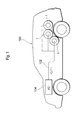
- FIG. 1 is a view showing a fuel cell vehicle equipped with high-pressure tanks 1 of the present embodiment.
- the fuel cell vehicle 100 is equipped with, for example, three high-pressure tanks 1 in a rear part of a vehicle body.
- Each high-pressure tank 1 constitutes a part of a fuel cell system and is configured to be capable of supplying a fuel gas to a fuel cell 104 through a gas supply line 102.
- the fuel gas stored in the high-pressure tank 1 is a flammable high-pressure gas, which is exemplified by compressed natural gas and hydrogen gas.
- the high-pressure tank 1 can be applied to not only fuel cell vehicles but also vehicles such as pure electric vehicles and hybrid electric vehicles, various movable bodies (for example, ships, airplanes, and robots), and stationary systems.
- the gas to be stored can include various compressed gases such as compressed natural gas (CNG) and various liquefied gases such as liquefied natural gas (LNG) and liquefied petroleum gas (LPG), for example.
- CNG compressed
- the high-pressure tank 1 includes a tank main body 10, a mouthpiece 20, a valve 30, a pipe 40, a temperature sensor 50, and other members.
- the tank main body 10 has a substantially ellipsoidal shape as a whole and includes a storage space for storing a fuel gas at a pressure higher than a normal pressure, in the inside.
- a fuel gas at a pressure higher than a normal pressure, in the inside.
- hydrogen gas or compressed natural gas is stored in the storage space at a pressure of, for example, 35 MPa to 70 MPa.
- the tank main body includes a two-layered wall, for example, and the wall includes a liner as the inner wall layer and a resin fiber layer
- the material for the liner is exemplified by polyethylene resins, polypropylene resins, and other hard resins.
- the liner may be configured as a laminate including a plurality of layers in which these resins are combined to form two or more layers.
- the reinforcement layer is, for example, a FRP (CFRP) layer produced by reinforcing a matrix resin (plastic) with carbon fibers.
- CFRP FRP
- the matrix resin include epoxy resins, modified epoxy resins, unsaturated polyester resins, and polypropylene resins.
- the mouthpiece 20 includes an opening having a substantially cylindrical shape and is fitted in the tank main body 10 (between the liner and the reinforcement layer) to be fixed.
- the opening of the mouthpiece 20 functions as the opening of the high-pressure tank 1.
- an attachment portion for example, an internal thread, which is not shown in drawings
- the valve 30 is detachably attached.
- the mouthpiece 20 is formed of stainless steel, but may be formed of another metal such as aluminum or a resin material.
- the valve 30 includes a valve main body 300 and a valve tube 302.
- the valve main body 300 is connected to the external gas supply line 102 (see FIG. 1 ) and is allowed to supply a fuel gas stored in the tank main body 10 when the fuel is used.
- the valve main body 300 is connected to an external fuel (hydrogen) station (not shown in drawings), for example, and is allowed to fill the fuel gas.
- an attachment portion for example, an external thread, which is not shown in drawings
- the structure of attaching and detaching the valve 30 to and from the mouthpiece 20 is not limited to the above, and other structures can be adopted.
- the mouthpiece 20 can be provided with a sealing member for shaft sealing between the inner peripheral face of the mouthpiece 20 and the valve 30.
- a pipe 40 and a temperature sensor 50 that extend in the axial direction (the direction indicated by Z in FIG. 2 ; the same is applied in the following drawings; also simply called “axial direction” in the description) of the tank main body 10 are connected.
- the pipe 40 and the temperature sensor 50 will next be described in detail with reference to FIG. 3 and FIG. 4 .
- the pipe 40 includes a first connection portion 406, a first bent portion 404, a second connection portion 402, and a second bent portion 400 from the valve tube 302 toward the tip of the pipe 40 and is fitted (screwed here) at one end of the first connection portion 406 to the valve tube 302 to be fixed.
- the first bent portion 404 is bent at an angle of ⁇ (-90° ⁇ ⁇ ⁇ 0°; for example, -45° in the present embodiment) with respect to the axial direction
- the second bent portion 400 of the pipe 40 is bent at an angle of ⁇ (0° ⁇ ⁇ ⁇ 90°; for example, 45° in the present embodiment) with respect to the axial direction.
- the first connection portion 406 and the second connection portion 402 of the pipe 40 extend in parallel with the axial direction.
- the pipe 40 extends in the axially inward direction of the tank main body 10 while bended at least twice in directions inclined relative to the axial direction.
- the pipe has a substantially U-shaped configuration between the first bent portion 404 and the second bent portion 400, and the pipe 40 has higher rigidity.
- the pipe 40 is thus unlikely to be distorted, and this can prevent the pipe from vibrating or making a strange sound due to an ejected gas.
- the pipe has the substantially U-shaped configuration between the first bent portion 404 and the second bent portion 400, and this can prevent the pipe from extending toward the radial direction of the tank main body 10 although the pipe is bended twice.
- the force from an ejected gas is applied to the pipe 40 in different directions between the first bent portion 404 and the second bent portion 400, and thus the force is efficiently dispersed. This further prevents the pipe 40 from vibrating or making a strange sound.
- the first connection portion 406 and the second connection portion 402 do not necessarily extend in parallel with the axial direction.
- a fuel gas ejection nozzle 400A is provided, so that a fuel gas is ejected into the storage space of the tank main body 10 in a direction inclined relative to the axial direction (at an angle indicated by ⁇ in FIG. 4 ).
- the fuel gas flows in a direction inclined relative to the axial direction and is reflected from the inner wall of the tank main body 10. This generates a vortex between the fuel gas that has been present in the tank main body and the freshly filled fuel gas and suppresses a local increase in temperature in the tank main body 10 due to adiabatic compression associated with high-pressure filling. Consequently, the temperature distribution in the tank main body 10 is equalized.
- the gas to be ejected into the tank main body 10 hits the second bent portion 400 to reduce the flow rate, and thus the temperature sensor 50 is prevented from breaking even when the gas is ejected around the temperature sensor 50.
- the ejection nozzle 400A is located at a position spaced apart from the valve, and thus a vortex is readily generated in the tank main body 10, thereby further equalizing the temperature distribution in the tank main body.
- the temperature sensor 50 includes a leading portion 500 that has one end attached to the valve 30 and extends in the axial direction and a sensor element 502 that connects to the other end of the leading portion 500 and is for measuring the gas temperature in the tank main body 10.
- the sensor element 502 is sufficiently spaced apart from the valve 30 but is located close to the valve 30 from the ejection nozzle 400A of the second bent portion 400 (in the embodiment, near the connection point between the second bent portion 400 and the second connection portion 402 of the pipe 40).
- the temperature sensor 50 is thus unlikely to be affected by chilliness from the valve 30.
- Such a structure can prevent direct ejection of a gas from the ejection nozzle 400A of the pipe 40 to the temperature sensor 50.
- the temperature sensor 50 is configured to be capable of measuring a mean temperature in the tank main body 10 more accurately.
- Accurate measurement of a mean temperature in the tank main body 10 is important from the following viewpoints.
- communication fueling for rapid fueling in the high-pressure tank 1 has been studied and developed in order to popularize and improve fuel cell vehicles.
- tank information including a gas mean temperature in the tank main body 10 is sent to a fuel station, and the fuel station determines the completion of fueling (full load) on the basis of a dispenser pressure and a mean temperature in the tank main body 10.
- accurate measurement of a mean temperature in the tank main body 10 enables more accurate detection of the degree of fueling in the tank main body 10.
- 1 high-pressure tank 10 tank main body, 20 mouthpiece, 30 valve, 300 valve main body, 302 valve tube, 302A fitting portion, 40 pipe, 406 first connection portion, 404 first bent portion, 402 second connection portion, 400 second bent portion, 400A ejection nozzle, 50 temperature sensor, 500 leading portion, 502 sensor element, 100 fuel cell vehicle, 102 gas supply line, 104 fuel cell, V virtual cylinder (column)
Landscapes
- Engineering & Computer Science (AREA)
- Mechanical Engineering (AREA)
- General Engineering & Computer Science (AREA)
- Life Sciences & Earth Sciences (AREA)
- Sustainable Development (AREA)
- Sustainable Energy (AREA)
- Chemical & Material Sciences (AREA)
- Combustion & Propulsion (AREA)
- Transportation (AREA)
- Filling Or Discharging Of Gas Storage Vessels (AREA)
- Electric Propulsion And Braking For Vehicles (AREA)
- Fuel Cell (AREA)
Abstract
Description
- The present invention relates to a high-pressure tank.
- As the containers for storing a high-pressure fuel gas (hydrogen gas) used for generating electric power with a fuel cell, high-pressure tanks produced by using a resin material for weight reduction are known. More specifically, a high-pressure tank having the structure produced by covering a thin-walled container (liner) made of a synthetic resin and including a housing space for storing hydrogen gas inside the container, with a layer reinforced by a fiber-reinforced resin and then curing the resin is known.
- As the valve for filling such a high-pressure tank with a gas, for example,
Patent Document 1 discloses a valve that includes a temperature sensor and can measure and monitor the temperature of gas in a tank when the tank is filled with the gas.Patent Document 1 describes an ejection nozzle through which a gas is ejected in a direction inclined relative to the axial direction of a tank in order to equalize the temperature distribution in the tank. - [Patent Document 1]
JP-A2013-64440 A - Here, the inventors have intended to elongate a pipe from a valve to provide a gas ejection nozzle in order to space the gas ejection nozzle a predetermined distance apart from the valve in the axial direction of a tank and to incline the gas ejection nozzle relative to the axial direction of the tank. In such a case, the inventors have found that an ejected gas may vibrate the pipe to make a strange sound.
- In view of the above circumstances, it is an object of the present invention to provide a high-pressure tank capable of suppressing a strange sound due to vibrations of a pipe.
- In order to solve the problem, according to a preferred aspect of the present invention, a high-pressure tank includes a tank main body including a mouthpiece, a valve fitted to the mouthpiece, and a pipe extending from the valve in an axially inward direction of the tank main body and for ejecting a gas into the tank main body. The pipe includes an ejection nozzle provided at an end of the pipe and for ejecting the gas, a first bent portion located between the ejection nozzle and the valve and extending in a direction inclined relative to an axial direction of the tank main body, and a second bent portion having the ejection nozzle and extending in a direction inclined relative to the axial direction. One of an inclination angle of the first bent portion relative to the axial direction and an inclination angle of the second bent portion relative to the axial direction is larger than 0° and not larger than 90°, and the other is not smaller than -90° and smaller than 0°, when the pipe is viewed in a direction perpendicular to the axial direction.
- With the structure, the valve is fitted to the mouthpiece of the tank main body; from the valve, the pipe extends in the axially inward direction of the tank main body; and from the ejection nozzle of the pipe, a gas is ejected into the tank main body. Accordingly, the gas is filled in the tank main body. Here, the ejection nozzle is provided at the end of the second bent portion that extends in a direction inclined relative to the axial direction of the tank main body. The gas ejected into the tank main body thus flows in a direction inclined relative to the axial direction of the tank main body and is reflected from the wall of the tank main body. This generates a vortex between the gas that has been present in the tank main body and the freshly filled gas and suppresses a local increase in temperature in the tank main body due to adiabatic compression associated with high-pressure filling. Consequently, the temperature distribution in the tank main body is equalized.
- The pipe includes two bent portions, the first bent portion and the second bent portion. In other words, the pipe is bent at least twice in directions inclined relative to the axial direction and extends in the axially inward direction of the tank main body. One of the inclination angle of the first bent portion relative to the axial direction and the inclination angle of the second bent portion relative to the axial direction is larger than 0° and not larger than 90°, and the other is not smaller than -90° and smaller than 0°. The bent angles of the first bent portion and the second bent portion have opposite signs relative to the axial direction of the tank, and thus the pipe forms a substantially U-shaped configuration between the first bent portion and the second bent portion. Due to this configuration, the pipe has higher rigidity and is unlikely to be distorted, and the force from an ejected gas to the pipe is efficiently dispersed. This can prevent the pipe from vibrating or making a strange sound. In addition, the pipe has the substantially U-shaped configuration between the first bent portion and the second bent portion, and this can prevent the pipe from extending toward the radial direction of the tank main body.
- The tank may further include a temperature sensor extending from the valve in the axially inward direction of the tank main body, and a tip of the temperature sensor may be located between the ejection nozzle of the pipe and the valve.
- With the structure, the temperature sensor extends from the valve in the axially inward direction of the tank main body and is located. The temperature sensor is thus unlikely to be affected by heat (chilliness) from the valve. In addition, the tip of the temperature sensor is located between the ejection nozzle of the pipe and the valve, and this can prevent direct ejection of a gas from the ejection nozzle of the pipe to the temperature sensor, enabling more accurate determination of the temperature in the tank main body.
- When such a virtual cylinder that a fitting portion where the valve is fitted to the mouthpiece is a bottom face and a side face of the fitting portion extends in the axial direction is imagined, the pipe and the temperature sensor may be located within the virtual cylinder.
- With the structure, the pipe and the temperature sensor are not positioned outside the fitting portion in the radial direction when viewed from the axial direction. On this account, when the valve is inserted from the mouthpiece of the tank main body along the axial direction, the pipe and the temperature sensor are prevented from hitting the mouthpiece and from being scratched.
- The present invention can provide a high-pressure tank capable of suppressing a strange sound due to vibrations of a pipe.
-
-
FIG. 1 is a view showing a fuel cell vehicle equipped with high-pressure tanks of a present embodiment. -
FIG. 2 is a diagram illustrating main elements of the high-pressure tank. -
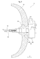
FIG. 3 is a perspective view of a main part of the high-pressure tank. -
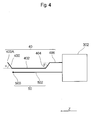
FIG. 4 is a schematic view illustrating the positional relation between a pipe and a temperature sensor. - Embodiments of the present invention will now be described in detail. In the drawings, the positional relations in terms of top, bottom, left, and right, for example, are based on the positional relations shown in the drawings unless otherwise specified. The dimensional ratios in the drawings are not necessarily limited to the ratios shown in the drawings. To make it easy to understand the descriptions, the same or similar elements in the drawings are indicated by the same or similar signs as possible, and duplicate descriptions are omitted. The following embodiments are exemplary embodiments for describing the present invention, and the present invention is not intended to be limited to these embodiments. The present invention can be variously modified without departing from the scope of the invention.
-
FIG. 1 is a view showing a fuel cell vehicle equipped with high-pressure tanks 1 of the present embodiment. Thefuel cell vehicle 100 is equipped with, for example, three high-pressure tanks 1 in a rear part of a vehicle body. Each high-pressure tank 1 constitutes a part of a fuel cell system and is configured to be capable of supplying a fuel gas to afuel cell 104 through agas supply line 102. The fuel gas stored in the high-pressure tank 1 is a flammable high-pressure gas, which is exemplified by compressed natural gas and hydrogen gas. The high-pressure tank 1 can be applied to not only fuel cell vehicles but also vehicles such as pure electric vehicles and hybrid electric vehicles, various movable bodies (for example, ships, airplanes, and robots), and stationary systems. The gas to be stored can include various compressed gases such as compressed natural gas (CNG) and various liquefied gases such as liquefied natural gas (LNG) and liquefied petroleum gas (LPG), for example. - As shown in
FIG. 2 , the high-pressure tank 1 includes a tankmain body 10, amouthpiece 20, avalve 30, apipe 40, atemperature sensor 50, and other members. - The tank
main body 10 has a substantially ellipsoidal shape as a whole and includes a storage space for storing a fuel gas at a pressure higher than a normal pressure, in the inside. For example, hydrogen gas or compressed natural gas is stored in the storage space at a pressure of, for example, 35 MPa to 70 MPa. The tank main body includes a two-layered wall, for example, and the wall includes a liner as the inner wall layer and a resin fiber layer - (reinforcement layer) as the outer wall layer on the outside of the liner. The material for the liner is exemplified by polyethylene resins, polypropylene resins, and other hard resins. The liner may be configured as a laminate including a plurality of layers in which these resins are combined to form two or more layers. The reinforcement layer is, for example, a FRP (CFRP) layer produced by reinforcing a matrix resin (plastic) with carbon fibers. Examples of the matrix resin include epoxy resins, modified epoxy resins, unsaturated polyester resins, and polypropylene resins.
- The
mouthpiece 20 includes an opening having a substantially cylindrical shape and is fitted in the tank main body 10 (between the liner and the reinforcement layer) to be fixed. The opening of themouthpiece 20 functions as the opening of the high-pressure tank 1. On the inner peripheral face of the opening in themouthpiece 20, an attachment portion (for example, an internal thread, which is not shown in drawings) is formed, and thevalve 30 is detachably attached. In the present embodiment, themouthpiece 20 is formed of stainless steel, but may be formed of another metal such as aluminum or a resin material. - The
valve 30 includes a valvemain body 300 and avalve tube 302. The valvemain body 300 is connected to the external gas supply line 102 (seeFIG. 1 ) and is allowed to supply a fuel gas stored in the tankmain body 10 when the fuel is used. When a fuel is filled, the valvemain body 300 is connected to an external fuel (hydrogen) station (not shown in drawings), for example, and is allowed to fill the fuel gas. On the outer peripheral face of thevalve tube 302, an attachment portion (for example, an external thread, which is not shown in drawings) is formed, and is fitted to the attachment portion formed on themouthpiece 20, thereby positioning thevalve 30 with respect to the tankmain body 10. The structure of attaching and detaching thevalve 30 to and from themouthpiece 20 is not limited to the above, and other structures can be adopted. For example, themouthpiece 20 can be provided with a sealing member for shaft sealing between the inner peripheral face of themouthpiece 20 and thevalve 30. - To the
valve tube 302, apipe 40 and atemperature sensor 50 that extend in the axial direction (the direction indicated by Z inFIG. 2 ; the same is applied in the following drawings; also simply called "axial direction" in the description) of the tankmain body 10 are connected. Thepipe 40 and thetemperature sensor 50 will next be described in detail with reference toFIG. 3 andFIG. 4 . - The
pipe 40 includes afirst connection portion 406, a firstbent portion 404, asecond connection portion 402, and a secondbent portion 400 from thevalve tube 302 toward the tip of thepipe 40 and is fitted (screwed here) at one end of thefirst connection portion 406 to thevalve tube 302 to be fixed. - As shown in
FIG. 4 , the firstbent portion 404 is bent at an angle of β (-90°≤ β < 0°; for example, -45° in the present embodiment) with respect to the axial direction, and the secondbent portion 400 of thepipe 40 is bent at an angle of α (0° < α ≤ 90°; for example, 45° in the present embodiment) with respect to the axial direction. Thefirst connection portion 406 and thesecond connection portion 402 of thepipe 40 extend in parallel with the axial direction. In other words, thepipe 40 extends in the axially inward direction of the tankmain body 10 while bended at least twice in directions inclined relative to the axial direction. Accordingly, the pipe has a substantially U-shaped configuration between the firstbent portion 404 and the secondbent portion 400, and thepipe 40 has higher rigidity. Thepipe 40 is thus unlikely to be distorted, and this can prevent the pipe from vibrating or making a strange sound due to an ejected gas. The pipe has the substantially U-shaped configuration between the firstbent portion 404 and the secondbent portion 400, and this can prevent the pipe from extending toward the radial direction of the tankmain body 10 although the pipe is bended twice. The force from an ejected gas is applied to thepipe 40 in different directions between the firstbent portion 404 and the secondbent portion 400, and thus the force is efficiently dispersed. This further prevents thepipe 40 from vibrating or making a strange sound. Thefirst connection portion 406 and thesecond connection portion 402 do not necessarily extend in parallel with the axial direction. - At one end of the second bent portion 400 (the tip of the pipe 40), a fuel
gas ejection nozzle 400A is provided, so that a fuel gas is ejected into the storage space of the tankmain body 10 in a direction inclined relative to the axial direction (at an angle indicated by α inFIG. 4 ). The fuel gas flows in a direction inclined relative to the axial direction and is reflected from the inner wall of the tankmain body 10. This generates a vortex between the fuel gas that has been present in the tank main body and the freshly filled fuel gas and suppresses a local increase in temperature in the tankmain body 10 due to adiabatic compression associated with high-pressure filling. Consequently, the temperature distribution in the tankmain body 10 is equalized. In addition, the gas to be ejected into the tankmain body 10 hits the secondbent portion 400 to reduce the flow rate, and thus thetemperature sensor 50 is prevented from breaking even when the gas is ejected around thetemperature sensor 50. - In this case, the
ejection nozzle 400A is located at a position spaced apart from the valve, and thus a vortex is readily generated in the tankmain body 10, thereby further equalizing the temperature distribution in the tank main body. - As shown in
FIG. 3 andFIG. 4 , thetemperature sensor 50 includes a leadingportion 500 that has one end attached to thevalve 30 and extends in the axial direction and asensor element 502 that connects to the other end of the leadingportion 500 and is for measuring the gas temperature in the tankmain body 10. Thesensor element 502 is sufficiently spaced apart from thevalve 30 but is located close to thevalve 30 from theejection nozzle 400A of the second bent portion 400 (in the embodiment, near the connection point between the secondbent portion 400 and thesecond connection portion 402 of the pipe 40). Thetemperature sensor 50 is thus unlikely to be affected by chilliness from thevalve 30. Such a structure can prevent direct ejection of a gas from theejection nozzle 400A of thepipe 40 to thetemperature sensor 50. In addition, as described above, a fuel gas is ejected in a direction inclined relative to the axial direction, and thus the temperature distribution in the tankmain body 10 is equalized. On this account, thetemperature sensor 50 is configured to be capable of measuring a mean temperature in the tankmain body 10 more accurately. - Accurate measurement of a mean temperature in the tank
main body 10 is important from the following viewpoints. In other words, communication fueling for rapid fueling in the high-pressure tank 1 has been studied and developed in order to popularize and improve fuel cell vehicles. In the communication fueling, tank information including a gas mean temperature in the tankmain body 10 is sent to a fuel station, and the fuel station determines the completion of fueling (full load) on the basis of a dispenser pressure and a mean temperature in the tankmain body 10. On this account, accurate measurement of a mean temperature in the tankmain body 10 enables more accurate detection of the degree of fueling in the tankmain body 10. - When such a virtual cylinder (column) V that a
fitting portion 302A where thevalve tube 302 is fitted to themouthpiece 20 is a bottom face and the side face of thefitting portion 302A extends in the axial direction is imagined as shown inFIG. 3 , thepipe 40 and thetemperature sensor 50 is located within the virtual cylinder V. In other words, thepipe 40 and thetemperature sensor 50 are not positioned outside thefitting portion 302A in the radial direction when viewed from the axial direction. On this account, when thevalve 30 is inserted from themouthpiece 20 along the axial direction, thepipe 40 and thetemperature sensor 50 are prevented from hitting themouthpiece 20 and from being scratched. - 1 high-pressure tank, 10 tank main body, 20 mouthpiece, 30 valve, 300 valve main body, 302 valve tube, 302A fitting portion, 40 pipe, 406 first connection portion, 404 first bent portion, 402 second connection portion, 400 second bent portion, 400A ejection nozzle, 50 temperature sensor, 500 leading portion, 502 sensor element, 100 fuel cell vehicle, 102 gas supply line, 104 fuel cell, V virtual cylinder (column)
Claims (3)
- A high-pressure tank (1) comprising:a tank main body (10) including a mouthpiece (20);a valve (30) fitted to the mouthpiece (20); anda pipe (40) extending from the valve (30) in an axially inward direction of the tank main body (10) and for ejecting a gas into the tank main body (10),the pipe (40) includingan ejection nozzle (400A) provided at an end of the pipe (40) and for ejecting the gas,a first bent portion (404) located between the ejection nozzle (400A) and the valve (30) and extending in a direction inclined relative to an axial direction of the tank main body (10), anda second bent portion (400) having the ejection nozzle (400A) and extending in a direction inclined relative to the axial direction,one of an inclination angle of the first bent portion (404) relative to the axial direction and an inclination angle of the second bent portion (400) relative to the axial direction being larger than 0° and not larger than 90°, and the other being not smaller than -90° and smaller than 0°, when the pipe (40) is viewed in a direction perpendicular to the axial direction.
- The high-pressure tank (1) according to claim 1, further comprising a temperature sensor (50) extending from the valve (30) in the axially inward direction of the tank main body (10), wherein a tip of the temperature sensor (50) is located between the ejection nozzle (400A) of the pipe (40) and the valve (30).
- The high-pressure tank (1) according to claim 2, wherein when such a virtual cylinder (V) that a fitting portion where the valve (30) is fitted to the mouthpiece (20) is a bottom face and a side face of the fitting portion extends in the axial direction is imagined, the pipe (40) and the temperature sensor (50) are located within the virtual cylinder (V).
Applications Claiming Priority (1)
| Application Number | Priority Date | Filing Date | Title |
|---|---|---|---|
| JP2014231825A JP6136076B2 (en) | 2014-11-14 | 2014-11-14 | High pressure tank |
Publications (2)
| Publication Number | Publication Date |
|---|---|
| EP3021031A1 true EP3021031A1 (en) | 2016-05-18 |
| EP3021031B1 EP3021031B1 (en) | 2019-05-29 |
Family
ID=54539862
Family Applications (1)
| Application Number | Title | Priority Date | Filing Date |
|---|---|---|---|
| EP15193486.6A Active EP3021031B1 (en) | 2014-11-14 | 2015-11-06 | Dip tube arrangement within a gas tank for liquefied or high pressure gases |
Country Status (6)
| Country | Link |
|---|---|
| US (1) | US9802480B2 (en) |
| EP (1) | EP3021031B1 (en) |
| JP (1) | JP6136076B2 (en) |
| KR (1) | KR101810744B1 (en) |
| CN (1) | CN105605412B (en) |
| CA (1) | CA2911572C (en) |
Cited By (5)
| Publication number | Priority date | Publication date | Assignee | Title |
|---|---|---|---|---|
| DE102022113027A1 (en) | 2022-05-24 | 2023-11-30 | Voith Patent Gmbh | Pressure tank for gas-powered vehicle and suitable manufacturing process |
| WO2023242510A1 (en) * | 2022-06-14 | 2023-12-21 | Ad-Venta | Outlet boss for a pressurized-fluid storage tank, and tank comprising such a boss |
| WO2024032980A1 (en) * | 2022-08-08 | 2024-02-15 | Robert Bosch Gmbh | Method for filling a fuel-gas tank with fuel gas, fuel-gas tank and fuel-tank system |
| WO2024088750A1 (en) * | 2022-10-25 | 2024-05-02 | Robert Bosch Gmbh | Tank system for a hydrogen-powered vehicle, fuel cell assembly, hydrogen internal combustion engine system, fuel cell-powered vehicle, and hydrogen-powered vehicle |
| WO2025036704A1 (en) * | 2023-08-14 | 2025-02-20 | Robert Bosch Gmbh | Tank system and method for checking a tank system comprising a plurality of high-pressure tanks |
Families Citing this family (6)
| Publication number | Priority date | Publication date | Assignee | Title |
|---|---|---|---|---|
| JP6770715B2 (en) * | 2016-12-27 | 2020-10-21 | トヨタ自動車株式会社 | High pressure tank |
| JP6677179B2 (en) * | 2017-01-16 | 2020-04-08 | トヨタ自動車株式会社 | tank |
| CN111712668B (en) * | 2018-01-19 | 2022-11-01 | 林德有限责任公司 | Low temperature container |
| KR102224134B1 (en) * | 2020-01-09 | 2021-03-08 | 한국이미지시스템(주) | Prestressed concrete pressure vessels |
| JP7781534B2 (en) * | 2021-03-23 | 2025-12-08 | トヨタ自動車株式会社 | Tank valve device |
| FR3158136A1 (en) * | 2024-01-08 | 2025-07-11 | L'air Liquide, Societe Anonyme Pour L'etude Et L'exploitation Des Procedes Georges Claude | Injector for a gas tank, and tank equipped with such an injector. |
Citations (7)
| Publication number | Priority date | Publication date | Assignee | Title |
|---|---|---|---|---|
| US3364688A (en) * | 1966-04-15 | 1968-01-23 | Ryan Ind Inc | Cryogenic container means |
| FR2763124A1 (en) * | 1997-05-09 | 1998-11-13 | Manotec Solution | SYSTEM AND METHOD FOR CAPACITIVE LEVEL MEASUREMENT OF A LIQUID IN A CONTAINER |
| CA2506606A1 (en) * | 2005-06-03 | 2005-11-14 | Westport Research Inc. | Storage tank for a cryogenic liquid and method of re-filling same |
| US20080141684A1 (en) * | 2006-12-18 | 2008-06-19 | Gm Global Technology Operations, Inc. | Liquid tank with combined liquid filling and liquid extraction conduit |
| CA2753588A1 (en) * | 2011-09-27 | 2013-03-27 | Westport Power Inc. | Apparatus and method for volume and mass estimation of a multiphase fluid stored at cryogenic temperatures |
| JP2013064440A (en) | 2011-09-16 | 2013-04-11 | Kawasaki Heavy Ind Ltd | Valve for fuel tank |
| US20140174571A1 (en) * | 2012-12-26 | 2014-06-26 | Kia Motors Corporation | Lpg bombe apparatus |
Family Cites Families (8)
| Publication number | Priority date | Publication date | Assignee | Title |
|---|---|---|---|---|
| JP4092104B2 (en) | 2001-12-26 | 2008-05-28 | 株式会社ネリキ | Valve device for gas cylinder |
| JP3864815B2 (en) * | 2002-03-14 | 2007-01-10 | 日産自動車株式会社 | Fuel tank structure |
| JP2005201342A (en) * | 2004-01-14 | 2005-07-28 | Toyota Motor Corp | High pressure gas filling system and high pressure gas filling method |
| KR20090075727A (en) * | 2004-08-23 | 2009-07-08 | 도요타 지도샤(주) | High pressure tank and valve assembly |
| WO2006082765A1 (en) * | 2005-02-02 | 2006-08-10 | Toyota Jidosha Kabushiki Kaisha | Seal structure of high-pressure tank |
| DE102007027281A1 (en) | 2007-06-11 | 2008-12-18 | Daimler Ag | High pressure gas tank and method for filling a high pressure gas tank |
| BRMU9101903Y1 (en) | 2011-09-30 | 2018-12-04 | Universidade Estadual De Campinas - Unicamp | vacuum chamber manifold solid phase extraction device, vacuum control valves and valves adapted for peristaltic pump control |
| CN202993702U (en) * | 2012-11-07 | 2013-06-12 | 江苏信成电器总厂 | Noise reduction structure of liquid storage device of evaporator |
-
2014
- 2014-11-14 JP JP2014231825A patent/JP6136076B2/en active Active
-
2015
- 2015-11-04 CN CN201510741081.5A patent/CN105605412B/en active Active
- 2015-11-06 EP EP15193486.6A patent/EP3021031B1/en active Active
- 2015-11-06 CA CA2911572A patent/CA2911572C/en active Active
- 2015-11-06 US US14/934,726 patent/US9802480B2/en active Active
- 2015-11-11 KR KR1020150158055A patent/KR101810744B1/en active Active
Patent Citations (7)
| Publication number | Priority date | Publication date | Assignee | Title |
|---|---|---|---|---|
| US3364688A (en) * | 1966-04-15 | 1968-01-23 | Ryan Ind Inc | Cryogenic container means |
| FR2763124A1 (en) * | 1997-05-09 | 1998-11-13 | Manotec Solution | SYSTEM AND METHOD FOR CAPACITIVE LEVEL MEASUREMENT OF A LIQUID IN A CONTAINER |
| CA2506606A1 (en) * | 2005-06-03 | 2005-11-14 | Westport Research Inc. | Storage tank for a cryogenic liquid and method of re-filling same |
| US20080141684A1 (en) * | 2006-12-18 | 2008-06-19 | Gm Global Technology Operations, Inc. | Liquid tank with combined liquid filling and liquid extraction conduit |
| JP2013064440A (en) | 2011-09-16 | 2013-04-11 | Kawasaki Heavy Ind Ltd | Valve for fuel tank |
| CA2753588A1 (en) * | 2011-09-27 | 2013-03-27 | Westport Power Inc. | Apparatus and method for volume and mass estimation of a multiphase fluid stored at cryogenic temperatures |
| US20140174571A1 (en) * | 2012-12-26 | 2014-06-26 | Kia Motors Corporation | Lpg bombe apparatus |
Cited By (5)
| Publication number | Priority date | Publication date | Assignee | Title |
|---|---|---|---|---|
| DE102022113027A1 (en) | 2022-05-24 | 2023-11-30 | Voith Patent Gmbh | Pressure tank for gas-powered vehicle and suitable manufacturing process |
| WO2023242510A1 (en) * | 2022-06-14 | 2023-12-21 | Ad-Venta | Outlet boss for a pressurized-fluid storage tank, and tank comprising such a boss |
| WO2024032980A1 (en) * | 2022-08-08 | 2024-02-15 | Robert Bosch Gmbh | Method for filling a fuel-gas tank with fuel gas, fuel-gas tank and fuel-tank system |
| WO2024088750A1 (en) * | 2022-10-25 | 2024-05-02 | Robert Bosch Gmbh | Tank system for a hydrogen-powered vehicle, fuel cell assembly, hydrogen internal combustion engine system, fuel cell-powered vehicle, and hydrogen-powered vehicle |
| WO2025036704A1 (en) * | 2023-08-14 | 2025-02-20 | Robert Bosch Gmbh | Tank system and method for checking a tank system comprising a plurality of high-pressure tanks |
Also Published As
| Publication number | Publication date |
|---|---|
| CN105605412A (en) | 2016-05-25 |
| KR20160058037A (en) | 2016-05-24 |
| US9802480B2 (en) | 2017-10-31 |
| JP2016095001A (en) | 2016-05-26 |
| US20160137056A1 (en) | 2016-05-19 |
| JP6136076B2 (en) | 2017-05-31 |
| CA2911572C (en) | 2017-07-25 |
| CN105605412B (en) | 2018-04-20 |
| CA2911572A1 (en) | 2016-05-14 |
| EP3021031B1 (en) | 2019-05-29 |
| KR101810744B1 (en) | 2017-12-19 |
Similar Documents
| Publication | Publication Date | Title |
|---|---|---|
| CA2911572C (en) | High-pressure tank | |
| US9057483B2 (en) | Threaded insert for compact cryogenic-capable pressure vessels | |
| US5383566A (en) | Dual-chamber composite pressure vessel and method of fabrication thereof | |
| US11204131B2 (en) | High pressure vessel | |
| JP5979446B2 (en) | Pressure vessel | |
| US8881932B1 (en) | Adapterless closure assembly for composite pressure vessels | |
| CN105683643A (en) | Fuel tank | |
| CN115614659B (en) | High-pressure tank unit | |
| US7028553B2 (en) | Apparatus for delivering pressurized fluid | |
| US11333301B2 (en) | Pressure vessel for the storage of pressurized fluids and vehicle comprising such a pressure vessel | |
| JP2017137929A (en) | Gas filling device and vehicle. | |
| KR102322371B1 (en) | Pressure vessel including reinforced cylinder part | |
| US9677713B1 (en) | Compact insert design for cryogenic pressure vessels | |
| US20220299162A1 (en) | High-pressure tank and method for manufacturing high-pressure tank | |
| US20140326000A1 (en) | LNG Tank Vapor Management Using a CNG Accumulator | |
| JP2018066426A (en) | Liquid hydrogen high pressure tank for transportation | |
| JP2014222081A (en) | High pressure gas container | |
| JP6677179B2 (en) | tank | |
| JP2019190523A (en) | Tank valve | |
| JP6733228B2 (en) | Pressure vessel | |
| KR20220089756A (en) | Conformable hydrogen tank having wrinkle part and its manufacturing method | |
| JP6770715B2 (en) | High pressure tank | |
| KR20230095660A (en) | Small Diameter Long Length High Pressure Vessel |
Legal Events
| Date | Code | Title | Description |
|---|---|---|---|
| PUAI | Public reference made under article 153(3) epc to a published international application that has entered the european phase |
Free format text: ORIGINAL CODE: 0009012 |
|
| 17P | Request for examination filed |
Effective date: 20151106 |
|
| AK | Designated contracting states |
Kind code of ref document: A1 Designated state(s): AL AT BE BG CH CY CZ DE DK EE ES FI FR GB GR HR HU IE IS IT LI LT LU LV MC MK MT NL NO PL PT RO RS SE SI SK SM TR |
|
| AX | Request for extension of the european patent |
Extension state: BA ME |
|
| GRAP | Despatch of communication of intention to grant a patent |
Free format text: ORIGINAL CODE: EPIDOSNIGR1 |
|
| STAA | Information on the status of an ep patent application or granted ep patent |
Free format text: STATUS: GRANT OF PATENT IS INTENDED |
|
| INTG | Intention to grant announced |
Effective date: 20190220 |
|
| GRAS | Grant fee paid |
Free format text: ORIGINAL CODE: EPIDOSNIGR3 |
|
| GRAA | (expected) grant |
Free format text: ORIGINAL CODE: 0009210 |
|
| STAA | Information on the status of an ep patent application or granted ep patent |
Free format text: STATUS: THE PATENT HAS BEEN GRANTED |
|
| AK | Designated contracting states |
Kind code of ref document: B1 Designated state(s): AL AT BE BG CH CY CZ DE DK EE ES FI FR GB GR HR HU IE IS IT LI LT LU LV MC MK MT NL NO PL PT RO RS SE SI SK SM TR |
|
| REG | Reference to a national code |
Ref country code: GB Ref legal event code: FG4D |
|
| REG | Reference to a national code |
Ref country code: CH Ref legal event code: EP |
|
| REG | Reference to a national code |
Ref country code: AT Ref legal event code: REF Ref document number: 1138464 Country of ref document: AT Kind code of ref document: T Effective date: 20190615 |
|
| REG | Reference to a national code |
Ref country code: DE Ref legal event code: R096 Ref document number: 602015031067 Country of ref document: DE |
|
| REG | Reference to a national code |
Ref country code: IE Ref legal event code: FG4D |
|
| REG | Reference to a national code |
Ref country code: DE Ref legal event code: R084 Ref document number: 602015031067 Country of ref document: DE |
|
| REG | Reference to a national code |
Ref country code: GB Ref legal event code: 746 Effective date: 20190806 |
|
| REG | Reference to a national code |
Ref country code: NO Ref legal event code: T2 Effective date: 20190529 |
|
| REG | Reference to a national code |
Ref country code: NL Ref legal event code: MP Effective date: 20190529 |
|
| REG | Reference to a national code |
Ref country code: LT Ref legal event code: MG4D |
|
| PG25 | Lapsed in a contracting state [announced via postgrant information from national office to epo] |
Ref country code: SE Free format text: LAPSE BECAUSE OF FAILURE TO SUBMIT A TRANSLATION OF THE DESCRIPTION OR TO PAY THE FEE WITHIN THE PRESCRIBED TIME-LIMIT Effective date: 20190529 Ref country code: LT Free format text: LAPSE BECAUSE OF FAILURE TO SUBMIT A TRANSLATION OF THE DESCRIPTION OR TO PAY THE FEE WITHIN THE PRESCRIBED TIME-LIMIT Effective date: 20190529 Ref country code: ES Free format text: LAPSE BECAUSE OF FAILURE TO SUBMIT A TRANSLATION OF THE DESCRIPTION OR TO PAY THE FEE WITHIN THE PRESCRIBED TIME-LIMIT Effective date: 20190529 Ref country code: PT Free format text: LAPSE BECAUSE OF FAILURE TO SUBMIT A TRANSLATION OF THE DESCRIPTION OR TO PAY THE FEE WITHIN THE PRESCRIBED TIME-LIMIT Effective date: 20190930 Ref country code: AL Free format text: LAPSE BECAUSE OF FAILURE TO SUBMIT A TRANSLATION OF THE DESCRIPTION OR TO PAY THE FEE WITHIN THE PRESCRIBED TIME-LIMIT Effective date: 20190529 Ref country code: HR Free format text: LAPSE BECAUSE OF FAILURE TO SUBMIT A TRANSLATION OF THE DESCRIPTION OR TO PAY THE FEE WITHIN THE PRESCRIBED TIME-LIMIT Effective date: 20190529 Ref country code: FI Free format text: LAPSE BECAUSE OF FAILURE TO SUBMIT A TRANSLATION OF THE DESCRIPTION OR TO PAY THE FEE WITHIN THE PRESCRIBED TIME-LIMIT Effective date: 20190529 |
|
| PG25 | Lapsed in a contracting state [announced via postgrant information from national office to epo] |
Ref country code: BG Free format text: LAPSE BECAUSE OF FAILURE TO SUBMIT A TRANSLATION OF THE DESCRIPTION OR TO PAY THE FEE WITHIN THE PRESCRIBED TIME-LIMIT Effective date: 20190829 Ref country code: RS Free format text: LAPSE BECAUSE OF FAILURE TO SUBMIT A TRANSLATION OF THE DESCRIPTION OR TO PAY THE FEE WITHIN THE PRESCRIBED TIME-LIMIT Effective date: 20190529 Ref country code: GR Free format text: LAPSE BECAUSE OF FAILURE TO SUBMIT A TRANSLATION OF THE DESCRIPTION OR TO PAY THE FEE WITHIN THE PRESCRIBED TIME-LIMIT Effective date: 20190830 Ref country code: LV Free format text: LAPSE BECAUSE OF FAILURE TO SUBMIT A TRANSLATION OF THE DESCRIPTION OR TO PAY THE FEE WITHIN THE PRESCRIBED TIME-LIMIT Effective date: 20190529 |
|
| REG | Reference to a national code |
Ref country code: AT Ref legal event code: MK05 Ref document number: 1138464 Country of ref document: AT Kind code of ref document: T Effective date: 20190529 |
|
| PG25 | Lapsed in a contracting state [announced via postgrant information from national office to epo] |
Ref country code: DK Free format text: LAPSE BECAUSE OF FAILURE TO SUBMIT A TRANSLATION OF THE DESCRIPTION OR TO PAY THE FEE WITHIN THE PRESCRIBED TIME-LIMIT Effective date: 20190529 Ref country code: EE Free format text: LAPSE BECAUSE OF FAILURE TO SUBMIT A TRANSLATION OF THE DESCRIPTION OR TO PAY THE FEE WITHIN THE PRESCRIBED TIME-LIMIT Effective date: 20190529 Ref country code: AT Free format text: LAPSE BECAUSE OF FAILURE TO SUBMIT A TRANSLATION OF THE DESCRIPTION OR TO PAY THE FEE WITHIN THE PRESCRIBED TIME-LIMIT Effective date: 20190529 Ref country code: SK Free format text: LAPSE BECAUSE OF FAILURE TO SUBMIT A TRANSLATION OF THE DESCRIPTION OR TO PAY THE FEE WITHIN THE PRESCRIBED TIME-LIMIT Effective date: 20190529 Ref country code: CZ Free format text: LAPSE BECAUSE OF FAILURE TO SUBMIT A TRANSLATION OF THE DESCRIPTION OR TO PAY THE FEE WITHIN THE PRESCRIBED TIME-LIMIT Effective date: 20190529 Ref country code: RO Free format text: LAPSE BECAUSE OF FAILURE TO SUBMIT A TRANSLATION OF THE DESCRIPTION OR TO PAY THE FEE WITHIN THE PRESCRIBED TIME-LIMIT Effective date: 20190529 Ref country code: NL Free format text: LAPSE BECAUSE OF FAILURE TO SUBMIT A TRANSLATION OF THE DESCRIPTION OR TO PAY THE FEE WITHIN THE PRESCRIBED TIME-LIMIT Effective date: 20190529 |
|
| PG25 | Lapsed in a contracting state [announced via postgrant information from national office to epo] |
Ref country code: IT Free format text: LAPSE BECAUSE OF FAILURE TO SUBMIT A TRANSLATION OF THE DESCRIPTION OR TO PAY THE FEE WITHIN THE PRESCRIBED TIME-LIMIT Effective date: 20190529 Ref country code: SM Free format text: LAPSE BECAUSE OF FAILURE TO SUBMIT A TRANSLATION OF THE DESCRIPTION OR TO PAY THE FEE WITHIN THE PRESCRIBED TIME-LIMIT Effective date: 20190529 |
|
| REG | Reference to a national code |
Ref country code: DE Ref legal event code: R097 Ref document number: 602015031067 Country of ref document: DE |
|
| PG25 | Lapsed in a contracting state [announced via postgrant information from national office to epo] |
Ref country code: TR Free format text: LAPSE BECAUSE OF FAILURE TO SUBMIT A TRANSLATION OF THE DESCRIPTION OR TO PAY THE FEE WITHIN THE PRESCRIBED TIME-LIMIT Effective date: 20190529 |
|
| PLBE | No opposition filed within time limit |
Free format text: ORIGINAL CODE: 0009261 |
|
| STAA | Information on the status of an ep patent application or granted ep patent |
Free format text: STATUS: NO OPPOSITION FILED WITHIN TIME LIMIT |
|
| PG25 | Lapsed in a contracting state [announced via postgrant information from national office to epo] |
Ref country code: PL Free format text: LAPSE BECAUSE OF FAILURE TO SUBMIT A TRANSLATION OF THE DESCRIPTION OR TO PAY THE FEE WITHIN THE PRESCRIBED TIME-LIMIT Effective date: 20190529 |
|
| 26N | No opposition filed |
Effective date: 20200303 |
|
| PG25 | Lapsed in a contracting state [announced via postgrant information from national office to epo] |
Ref country code: SI Free format text: LAPSE BECAUSE OF FAILURE TO SUBMIT A TRANSLATION OF THE DESCRIPTION OR TO PAY THE FEE WITHIN THE PRESCRIBED TIME-LIMIT Effective date: 20190529 |
|
| REG | Reference to a national code |
Ref country code: CH Ref legal event code: PL |
|
| PG25 | Lapsed in a contracting state [announced via postgrant information from national office to epo] |
Ref country code: MC Free format text: LAPSE BECAUSE OF FAILURE TO SUBMIT A TRANSLATION OF THE DESCRIPTION OR TO PAY THE FEE WITHIN THE PRESCRIBED TIME-LIMIT Effective date: 20190529 Ref country code: LU Free format text: LAPSE BECAUSE OF NON-PAYMENT OF DUE FEES Effective date: 20191106 Ref country code: CH Free format text: LAPSE BECAUSE OF NON-PAYMENT OF DUE FEES Effective date: 20191130 Ref country code: LI Free format text: LAPSE BECAUSE OF NON-PAYMENT OF DUE FEES Effective date: 20191130 |
|
| REG | Reference to a national code |
Ref country code: BE Ref legal event code: MM Effective date: 20191130 |
|
| PG25 | Lapsed in a contracting state [announced via postgrant information from national office to epo] |
Ref country code: IE Free format text: LAPSE BECAUSE OF NON-PAYMENT OF DUE FEES Effective date: 20191106 |
|
| PG25 | Lapsed in a contracting state [announced via postgrant information from national office to epo] |
Ref country code: BE Free format text: LAPSE BECAUSE OF NON-PAYMENT OF DUE FEES Effective date: 20191130 |
|
| PG25 | Lapsed in a contracting state [announced via postgrant information from national office to epo] |
Ref country code: CY Free format text: LAPSE BECAUSE OF FAILURE TO SUBMIT A TRANSLATION OF THE DESCRIPTION OR TO PAY THE FEE WITHIN THE PRESCRIBED TIME-LIMIT Effective date: 20190529 |
|
| PG25 | Lapsed in a contracting state [announced via postgrant information from national office to epo] |
Ref country code: IS Free format text: LAPSE BECAUSE OF FAILURE TO SUBMIT A TRANSLATION OF THE DESCRIPTION OR TO PAY THE FEE WITHIN THE PRESCRIBED TIME-LIMIT Effective date: 20190929 |
|
| PG25 | Lapsed in a contracting state [announced via postgrant information from national office to epo] |
Ref country code: MT Free format text: LAPSE BECAUSE OF FAILURE TO SUBMIT A TRANSLATION OF THE DESCRIPTION OR TO PAY THE FEE WITHIN THE PRESCRIBED TIME-LIMIT Effective date: 20190529 Ref country code: HU Free format text: LAPSE BECAUSE OF FAILURE TO SUBMIT A TRANSLATION OF THE DESCRIPTION OR TO PAY THE FEE WITHIN THE PRESCRIBED TIME-LIMIT; INVALID AB INITIO Effective date: 20151106 |
|
| PGFP | Annual fee paid to national office [announced via postgrant information from national office to epo] |
Ref country code: NO Payment date: 20211109 Year of fee payment: 7 |
|
| PG25 | Lapsed in a contracting state [announced via postgrant information from national office to epo] |
Ref country code: MK Free format text: LAPSE BECAUSE OF FAILURE TO SUBMIT A TRANSLATION OF THE DESCRIPTION OR TO PAY THE FEE WITHIN THE PRESCRIBED TIME-LIMIT Effective date: 20190529 |
|
| P01 | Opt-out of the competence of the unified patent court (upc) registered |
Effective date: 20230427 |
|
| REG | Reference to a national code |
Ref country code: NO Ref legal event code: MMEP |
|
| PG25 | Lapsed in a contracting state [announced via postgrant information from national office to epo] |
Ref country code: NO Free format text: LAPSE BECAUSE OF NON-PAYMENT OF DUE FEES Effective date: 20221130 |
|
| PGFP | Annual fee paid to national office [announced via postgrant information from national office to epo] |
Ref country code: FR Payment date: 20250930 Year of fee payment: 11 |
|
| PGFP | Annual fee paid to national office [announced via postgrant information from national office to epo] |
Ref country code: DE Payment date: 20250930 Year of fee payment: 11 |
|
| PGFP | Annual fee paid to national office [announced via postgrant information from national office to epo] |
Ref country code: GB Payment date: 20251001 Year of fee payment: 11 |