EP3021014A1 - Dichtungselement - Google Patents
Dichtungselement Download PDFInfo
- Publication number
- EP3021014A1 EP3021014A1 EP15192739.9A EP15192739A EP3021014A1 EP 3021014 A1 EP3021014 A1 EP 3021014A1 EP 15192739 A EP15192739 A EP 15192739A EP 3021014 A1 EP3021014 A1 EP 3021014A1
- Authority
- EP
- European Patent Office
- Prior art keywords
- annular sealing
- sealing element
- groove
- annular
- sealing profile
- Prior art date
- Legal status (The legal status is an assumption and is not a legal conclusion. Google has not performed a legal analysis and makes no representation as to the accuracy of the status listed.)
- Ceased
Links
- 238000007789 sealing Methods 0.000 claims abstract description 31
- 239000004698 Polyethylene Substances 0.000 claims description 6
- -1 polyethylene Polymers 0.000 claims description 6
- 229920000573 polyethylene Polymers 0.000 claims description 6
- 229920001343 polytetrafluoroethylene Polymers 0.000 claims description 6
- 239000004810 polytetrafluoroethylene Substances 0.000 claims description 6
- IXURVUHDDXFYDR-UHFFFAOYSA-N 1-[4-(difluoromethoxy)-3-(oxolan-3-yloxy)phenyl]-3-methylbutan-1-one Chemical compound CC(C)CC(=O)C1=CC=C(OC(F)F)C(OC2COCC2)=C1 IXURVUHDDXFYDR-UHFFFAOYSA-N 0.000 claims description 3
- 229920006169 Perfluoroelastomer Polymers 0.000 claims description 3
- 229920001971 elastomer Polymers 0.000 claims description 3
- RYGMFSIKBFXOCR-UHFFFAOYSA-N Copper Chemical compound [Cu] RYGMFSIKBFXOCR-UHFFFAOYSA-N 0.000 description 10
- 229910052802 copper Inorganic materials 0.000 description 10
- 239000010949 copper Substances 0.000 description 10
- 229910052782 aluminium Inorganic materials 0.000 description 5
- XAGFODPZIPBFFR-UHFFFAOYSA-N aluminium Chemical compound [Al] XAGFODPZIPBFFR-UHFFFAOYSA-N 0.000 description 5
- 238000006056 electrooxidation reaction Methods 0.000 description 4
- 229910052751 metal Inorganic materials 0.000 description 3
- 239000002184 metal Substances 0.000 description 3
- 150000002739 metals Chemical class 0.000 description 3
- 238000013459 approach Methods 0.000 description 1
- 239000011248 coating agent Substances 0.000 description 1
- 238000000576 coating method Methods 0.000 description 1
- 150000001875 compounds Chemical class 0.000 description 1
- 230000001419 dependent effect Effects 0.000 description 1
- 239000004033 plastic Substances 0.000 description 1
- 229920003023 plastic Polymers 0.000 description 1
Images

Classifications
-
- F—MECHANICAL ENGINEERING; LIGHTING; HEATING; WEAPONS; BLASTING
- F16—ENGINEERING ELEMENTS AND UNITS; GENERAL MEASURES FOR PRODUCING AND MAINTAINING EFFECTIVE FUNCTIONING OF MACHINES OR INSTALLATIONS; THERMAL INSULATION IN GENERAL
- F16J—PISTONS; CYLINDERS; SEALINGS
- F16J15/00—Sealings
- F16J15/02—Sealings between relatively-stationary surfaces
- F16J15/06—Sealings between relatively-stationary surfaces with solid packing compressed between sealing surfaces
- F16J15/10—Sealings between relatively-stationary surfaces with solid packing compressed between sealing surfaces with non-metallic packing
- F16J15/104—Sealings between relatively-stationary surfaces with solid packing compressed between sealing surfaces with non-metallic packing characterised by structure
-
- F—MECHANICAL ENGINEERING; LIGHTING; HEATING; WEAPONS; BLASTING
- F16—ENGINEERING ELEMENTS AND UNITS; GENERAL MEASURES FOR PRODUCING AND MAINTAINING EFFECTIVE FUNCTIONING OF MACHINES OR INSTALLATIONS; THERMAL INSULATION IN GENERAL
- F16J—PISTONS; CYLINDERS; SEALINGS
- F16J15/00—Sealings
- F16J15/02—Sealings between relatively-stationary surfaces
- F16J15/06—Sealings between relatively-stationary surfaces with solid packing compressed between sealing surfaces
- F16J15/10—Sealings between relatively-stationary surfaces with solid packing compressed between sealing surfaces with non-metallic packing
- F16J15/102—Sealings between relatively-stationary surfaces with solid packing compressed between sealing surfaces with non-metallic packing characterised by material
-
- F—MECHANICAL ENGINEERING; LIGHTING; HEATING; WEAPONS; BLASTING
- F16—ENGINEERING ELEMENTS AND UNITS; GENERAL MEASURES FOR PRODUCING AND MAINTAINING EFFECTIVE FUNCTIONING OF MACHINES OR INSTALLATIONS; THERMAL INSULATION IN GENERAL
- F16J—PISTONS; CYLINDERS; SEALINGS
- F16J15/00—Sealings
- F16J15/16—Sealings between relatively-moving surfaces
- F16J15/32—Sealings between relatively-moving surfaces with elastic sealings, e.g. O-rings
- F16J15/3284—Sealings between relatively-moving surfaces with elastic sealings, e.g. O-rings characterised by their structure; Selection of materials
-
- F—MECHANICAL ENGINEERING; LIGHTING; HEATING; WEAPONS; BLASTING
- F16—ENGINEERING ELEMENTS AND UNITS; GENERAL MEASURES FOR PRODUCING AND MAINTAINING EFFECTIVE FUNCTIONING OF MACHINES OR INSTALLATIONS; THERMAL INSULATION IN GENERAL
- F16L—PIPES; JOINTS OR FITTINGS FOR PIPES; SUPPORTS FOR PIPES, CABLES OR PROTECTIVE TUBING; MEANS FOR THERMAL INSULATION IN GENERAL
- F16L25/00—Construction or details of pipe joints not provided for in, or of interest apart from, groups F16L13/00 - F16L23/00
- F16L25/0072—Joints for pipes of dissimilar materials
-
- F—MECHANICAL ENGINEERING; LIGHTING; HEATING; WEAPONS; BLASTING
- F16—ENGINEERING ELEMENTS AND UNITS; GENERAL MEASURES FOR PRODUCING AND MAINTAINING EFFECTIVE FUNCTIONING OF MACHINES OR INSTALLATIONS; THERMAL INSULATION IN GENERAL
- F16L—PIPES; JOINTS OR FITTINGS FOR PIPES; SUPPORTS FOR PIPES, CABLES OR PROTECTIVE TUBING; MEANS FOR THERMAL INSULATION IN GENERAL
- F16L25/00—Construction or details of pipe joints not provided for in, or of interest apart from, groups F16L13/00 - F16L23/00
- F16L25/02—Construction or details of pipe joints not provided for in, or of interest apart from, groups F16L13/00 - F16L23/00 specially adapted for electrically insulating the two pipe ends of the joint from each other
- F16L25/025—Construction or details of pipe joints not provided for in, or of interest apart from, groups F16L13/00 - F16L23/00 specially adapted for electrically insulating the two pipe ends of the joint from each other for joints with sleeve or socket
Definitions
- the invention relates to an annular sealing element which is inserted between two different metals.
- the aim of the invention is to avoid the disadvantages of the prior art and to propose a simple annular sealing element of the type mentioned, which avoids electrochemical corrosion.
- this is achieved in that, in the case of an annular sealing element with an annular sealing profile, a wing-shaped projection is arranged perpendicular to the ring line on at least one side, which groove forms a groove with the annular sealing profile form.
- This groove is suitable for coating a corresponding metallic collar, so that the collar does not come into contact with the body to be sealed, so that the electrochemical corrosion is avoided.
- the annular sealing element is preferably in one piece, so that the wing-shaped projection on the one hand captive and on the other hand, the sealing element can be produced in one operation.
- the annular sealing element is preferably made of rubber, perfluororubber (FFKM or FFPM), polyethylene (PE) or polytetrafluoroethylene (PTFE).
- FFKM or FFPM perfluororubber
- PE polyethylene
- PTFE polytetrafluoroethylene
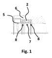
- FIG. 1 shows a copper pipe 5, which is connected to an aluminum heat exchanger 6.
- the copper tube 5 has an annular groove 7, which is formed by two folded frets 8. In this annular groove 7 there is an annular sealing profile 2. Since the collars 8 of the copper tube 5 can come into contact with the aluminum heat exchanger 6, electrochemical corrosion can occur.
- FIG. 2 shows the annular sealing element 1 according to the invention with annular sealing profile 2 and two wing-shaped projections 3 perpendicular to the ring line on both sides.
- the wing-shaped projections 3 form a groove 4 with the annular sealing profile 2.
- the annular sealing element 1 is in this case made in one piece from rubber, perfluororubber (FFKM or FFPM), polyethylene (PE) or polytetrafluoroethylene (PTFE).
- FIG. 3 shows the inventive annular sealing element 1 with annular sealing profile 2 on a copper tube 5, which has an annular groove 7, which are formed by two collars 8 of the copper tube 5.
- the annular sealing profile 2 is located in the annular groove 7.
- the grooves 4 of the annular sealing element 1 cover the two frets 8 of the copper tube 5, so that they can not come into contact with other metals.
- the right wing-shaped projection 3 in particular covers the end face of the copper tube 5, so that the copper tube 5 can not come into direct contact with it when it is inserted into a corresponding, metallic body.
Landscapes
- Engineering & Computer Science (AREA)
- General Engineering & Computer Science (AREA)
- Mechanical Engineering (AREA)
- Gasket Seals (AREA)
Abstract
Description
- Die Erfindung bezieht sich auf ein ringförmiges Dichtungselement, welches zwischen zwei unterschiedlichen Metallen eingesetzt wird.
- Bei Dichtungen zwischen beispielsweise Aluminium und Kupfer kann es zu einer elektrochemischen Korrosion des Aluminiums kommen. Gemäß dem Stand der Technik sind bei ringförmigen Dichtungen Kunststoffbuchsen bekannt, welche zwischen den beiden Metallen eine direkte Verbindung vermeiden sollen. Dies bedingt ein weiteres Bauteil und somit entsprechende Kosten.
- Ziel der Erfindung ist es, die Nachteile des Standes der Technik zu vermeiden und ein einfaches ringförmiges Dichtungselement der eingangs erwähnten Art vorzuschlagen, welche elektrochemische Korrosion vermeidet.
- Erfindungsgemäß wird dies dadurch gelöst, dass bei einem ringförmigen Dichtungselement mit einem ringförmigen Dichtprofil senkrecht zur Ringlinie an mindestens einer Seite ein flügelförmiger Ansatz angeordnet ist, welcher mit dem ringförmigen Dichtprofil eine Nut bilden. Diese Nut eignet sich zum Überzug eines korrespondierenden, metallischen Bundes, so dass der Bund nicht in Kontakt mit dem abzudichtenden Körper tritt, so dass die elektrochemische Korrosion vermieden wird.
- Vorteilhafte Ausgestaltungen ergeben sich durch die Merkmale der abhängigen Ansprüche.
- So ist das ringförmige Dichtungselement bevorzugt einstückig, so dass der flügelförmige Ansatz einerseits unverlierbar und andererseits das Dichtungselement in einem Arbeitsgang herstellbar ist.
- Das ringförmige Dichtungselement ist bevorzugt aus Kautschuk, Perfluorkautschuk (FFKM oder FFPM), Polyethylen (PE) oder Polytetrafluorethylen (PTFE) hergestellt.
- Die Erfindung wird nun anhand der Zeichnung näher erläutert. Dabei zeigen:
-
Fig. 1 eine Verbindung gemäß dem Stand der Technik -
Fig. 2 ein erfindungsgemäßes ringförmige Dichtungselement sowie -
Fig. 3 ein montiertes erfindungsgemäßes ringförmige Dichtungselement. -
Figur 1 zeigt ein Kupferrohr 5, das mit einem Aluminium-Wärmetauscher 6 verbunden ist. Das Kupferrohr 5 verfügt über eine Ringnut 7, welche durch zwei gefaltete Bünde 8 gebildet wird. In dieser Ringnut 7 befindet sich ein ringförmigen Dichtprofil 2. Da die Bünde 8 des Kupferrohrs 5 in Kontakt mit dem Aluminium-Wärmetauscher 6 treten können, kann elektrochemische Korrosion entstehen. -
Figur 2 zeigt das erfindungsgemäße ringförmige Dichtungselement 1 mit ringförmigem Dichtprofil 2 und zwei flügelförmigen Ansätze 3 senkrecht zur Ringlinie an beiden Seiten. Die flügelförmigen Ansätze 3 bilden mit dem ringförmigen Dichtprofil 2 eine Nut 4. Das ringförmige Dichtungselement 1 ist hierbei einstückig aus Kautschuk, Perfluorkautschuk (FFKM oder FFPM), Polyethylen (PE) oder Polytetrafluorethylen (PTFE)hergestellt. -
Figur 3 zeigt das erfindungsgemäße ringförmige Dichtungselement 1 mit ringförmigem Dichtprofil 2 auf einem Kupferrohr 5, welches über eine Ringnut 7 verfügt, welche durch zwei Bünde 8 des Kupferrohres 5 gebildet werden. Das mit ringförmige Dichtprofil 2 befindet sich in der Ringnut 7. Die Nuten 4 des ringförmigen Dichtungselements 1 überdecken die zwei Bünde 8 des Kupferrohres 5, so dass diese nicht in Kontakt mit anderen Metallen treten können. Hierbei überdeckt insbesondere der rechte flügelförmige Ansatz 3 die Stirnseite des Kupferrohres 5 überdeckt, so dass das Kupferrohr 5 beim Einstecken in einen korrespondierenden, metallischen Körper nicht in direkten Kontakt mit diesem treten kann. -
- 1
- ringförmiges Dichtungselement
- 2
- ringförmigem Dichtprofil
- 3
- flügelförmige Ansätze
- 4
- Nut
- 5
- Kupferrohr
- 6
- Aluminium-Wärmetauscher
- 7
- Ringnut
- 8
- Bund
Claims (3)
- Ringförmiges Dichtungselement (1) mit einem ringförmigen Dichtprofil (2), dadurch gekennzeichnet, dass senkrecht zur Ringlinie an einer oder zwei Seiten flügelförmige Ansätze (3) angeordnet sind, welche mit dem ringförmigen Dichtprofil (2) eine Nut (4) bilden.
- Ringförmiges Dichtungselement (1) nach Anspruch 1, dadurch gekennzeichnet, dass das ringförmige Dichtungselement (1) einstückig ist.
- Ringförmiges Dichtungselement (1) nach Anspruch 1 oder 2, dadurch gekennzeichnet, dass das ringförmige Dichtungselement (1) aus Kautschuk, Perfluorkautschuk (FFKM oder FFPM), Polyethylen (PE) oder Polytetrafluorethylen (PTFE)hergestellt ist.
Applications Claiming Priority (1)
| Application Number | Priority Date | Filing Date | Title |
|---|---|---|---|
| DE102014223244.9A DE102014223244A1 (de) | 2014-11-14 | 2014-11-14 | Dichtungselement |
Publications (1)
| Publication Number | Publication Date |
|---|---|
| EP3021014A1 true EP3021014A1 (de) | 2016-05-18 |
Family
ID=54396777
Family Applications (1)
| Application Number | Title | Priority Date | Filing Date |
|---|---|---|---|
| EP15192739.9A Ceased EP3021014A1 (de) | 2014-11-14 | 2015-11-03 | Dichtungselement |
Country Status (2)
| Country | Link |
|---|---|
| EP (1) | EP3021014A1 (de) |
| DE (1) | DE102014223244A1 (de) |
Citations (7)
| Publication number | Priority date | Publication date | Assignee | Title |
|---|---|---|---|---|
| US3720420A (en) * | 1971-03-19 | 1973-03-13 | Parker Hannifin Corp | Gasket |
| EP0877189A2 (de) * | 1997-04-30 | 1998-11-11 | Forsheda AB | Dichtvorrichtung |
| GB2331334A (en) * | 1997-10-03 | 1999-05-19 | Shaun Henry | A gasket seal |
| US5971399A (en) * | 1993-08-17 | 1999-10-26 | Chiyoda Corporation | Dual density sanitary pipe gasket |
| GB2375149A (en) * | 2001-03-26 | 2002-11-06 | John Henry | A gasket |
| JP2004204941A (ja) * | 2002-12-25 | 2004-07-22 | Keeper Co Ltd | ガスケット |
| US20040160018A1 (en) * | 2003-02-14 | 2004-08-19 | Dupont Paul Robert | Gasket for sanitary fittings |
Family Cites Families (1)
| Publication number | Priority date | Publication date | Assignee | Title |
|---|---|---|---|---|
| DE102011081973A1 (de) * | 2011-09-01 | 2013-03-07 | Federal-Mogul Sealing Systems Gmbh | Profildichtung mit Randabdichtung |
-
2014
- 2014-11-14 DE DE102014223244.9A patent/DE102014223244A1/de not_active Withdrawn
-
2015
- 2015-11-03 EP EP15192739.9A patent/EP3021014A1/de not_active Ceased
Patent Citations (7)
| Publication number | Priority date | Publication date | Assignee | Title |
|---|---|---|---|---|
| US3720420A (en) * | 1971-03-19 | 1973-03-13 | Parker Hannifin Corp | Gasket |
| US5971399A (en) * | 1993-08-17 | 1999-10-26 | Chiyoda Corporation | Dual density sanitary pipe gasket |
| EP0877189A2 (de) * | 1997-04-30 | 1998-11-11 | Forsheda AB | Dichtvorrichtung |
| GB2331334A (en) * | 1997-10-03 | 1999-05-19 | Shaun Henry | A gasket seal |
| GB2375149A (en) * | 2001-03-26 | 2002-11-06 | John Henry | A gasket |
| JP2004204941A (ja) * | 2002-12-25 | 2004-07-22 | Keeper Co Ltd | ガスケット |
| US20040160018A1 (en) * | 2003-02-14 | 2004-08-19 | Dupont Paul Robert | Gasket for sanitary fittings |
Also Published As
| Publication number | Publication date |
|---|---|
| DE102014223244A1 (de) | 2016-05-19 |
Similar Documents
| Publication | Publication Date | Title |
|---|---|---|
| EP2893241B1 (de) | Fitting, system mit einem solchen fitting und dichte verbindung mit einem solchen fitting | |
| EP3255329B1 (de) | Rohrleitungsfitting mit schwingungskompensator | |
| EP3322929B1 (de) | Kupplungsarmatur für rohrleitungen | |
| DE10085364B4 (de) | Bauteil-zu-Bauteil Dichtverfahren | |
| AT397843B (de) | Übergangsstück aus kunststoff zum verbinden von kunststoffrohren mit armaturen oder rohren aus metallischen werkstoffen | |
| DE202014102317U1 (de) | Muffe zur Verbindung von Kabel und Wellenrohr mit einem Vielfachschutz gegen Luft, Wasser und Zugkraft | |
| EP1412668A1 (de) | Pressfitting für rohre | |
| DE112012002695B4 (de) | Schlauchkupplung, insbesondere für hydraulische Hochdruckleitungen eines Ausrücksystems | |
| DE3132602A1 (de) | Radiator | |
| WO2014131510A1 (de) | Flachdichtung für flanschverbindungen | |
| DE102014223244A1 (de) | Dichtungselement | |
| EP3115671A1 (de) | Transition fitting | |
| EP1306601A2 (de) | Pressfitting für den Anschluss mindestens eines Rohres | |
| DE19516830A1 (de) | Preßwerkzeuge und Verfahren zum Verbinden von rohrförmigen Elementen | |
| DE102007035930A1 (de) | Multi-Crimp-Schlauchschelle | |
| WO2017102124A1 (de) | Rohrverbinder | |
| DE202014101748U1 (de) | Schraubverbindungsvorrichtung zur Verbindung zweier Rohre | |
| EP3124848A1 (de) | Anschlussarmatur für eine fluidleitung | |
| DE202012002893U1 (de) | Sanitär-Fitting mit lösbarer Verbindung und Baukasten | |
| DE102008003675B4 (de) | Anschlussstück für ein Metallrohr oder einen Metallschlauch und Anordnung mit einem solchen Anschlussstück | |
| DE102018125649A1 (de) | Montage von reifenventilen | |
| DE102016100405A1 (de) | Steckverbindung zur Verbindung von Rohren mit ovalem Querschnitt | |
| DE202012002791U1 (de) | Anschlussvorrichtung für einen ringgewellten Metallschlauch | |
| DE2439717A1 (de) | Universal-verschraubung fuer loetanschluesse und klemmring-verschraubung mit unterschiedlichen rohrdurchmessern, insbesondere fuer verteiler-verschraubung fuer ein- und/oder zweirohrheizungen | |
| DE20319278U1 (de) | Rohrverbindung |
Legal Events
| Date | Code | Title | Description |
|---|---|---|---|
| PUAI | Public reference made under article 153(3) epc to a published international application that has entered the european phase |
Free format text: ORIGINAL CODE: 0009012 |
|
| AK | Designated contracting states |
Kind code of ref document: A1 Designated state(s): AL AT BE BG CH CY CZ DE DK EE ES FI FR GB GR HR HU IE IS IT LI LT LU LV MC MK MT NL NO PL PT RO RS SE SI SK SM TR |
|
| AX | Request for extension of the european patent |
Extension state: BA ME |
|
| 17P | Request for examination filed |
Effective date: 20161028 |
|
| RBV | Designated contracting states (corrected) |
Designated state(s): AL AT BE BG CH CY CZ DE DK EE ES FI FR GB GR HR HU IE IS IT LI LT LU LV MC MK MT NL NO PL PT RO RS SE SI SK SM TR |
|
| 17Q | First examination report despatched |
Effective date: 20170309 |
|
| STAA | Information on the status of an ep patent application or granted ep patent |
Free format text: STATUS: THE APPLICATION HAS BEEN REFUSED |
|
| 18R | Application refused |
Effective date: 20181224 |