EP3020999A1 - Aircraft brake puck assembly - Google Patents
Aircraft brake puck assembly Download PDFInfo
- Publication number
- EP3020999A1 EP3020999A1 EP15192699.5A EP15192699A EP3020999A1 EP 3020999 A1 EP3020999 A1 EP 3020999A1 EP 15192699 A EP15192699 A EP 15192699A EP 3020999 A1 EP3020999 A1 EP 3020999A1
- Authority
- EP
- European Patent Office
- Prior art keywords
- retaining ring
- puck
- endcap
- ema
- base
- Prior art date
- Legal status (The legal status is an assumption and is not a legal conclusion. Google has not performed a legal analysis and makes no representation as to the accuracy of the status listed.)
- Granted
Links
Images




Classifications
-
- B—PERFORMING OPERATIONS; TRANSPORTING
- B64—AIRCRAFT; AVIATION; COSMONAUTICS
- B64C—AEROPLANES; HELICOPTERS
- B64C25/00—Alighting gear
- B64C25/32—Alighting gear characterised by elements which contact the ground or similar surface
- B64C25/42—Arrangement or adaptation of brakes
- B64C25/44—Actuating mechanisms
-
- F—MECHANICAL ENGINEERING; LIGHTING; HEATING; WEAPONS; BLASTING
- F16—ENGINEERING ELEMENTS AND UNITS; GENERAL MEASURES FOR PRODUCING AND MAINTAINING EFFECTIVE FUNCTIONING OF MACHINES OR INSTALLATIONS; THERMAL INSULATION IN GENERAL
- F16D—COUPLINGS FOR TRANSMITTING ROTATION; CLUTCHES; BRAKES
- F16D65/00—Parts or details
- F16D65/14—Actuating mechanisms for brakes; Means for initiating operation at a predetermined position
- F16D65/16—Actuating mechanisms for brakes; Means for initiating operation at a predetermined position arranged in or on the brake
- F16D65/18—Actuating mechanisms for brakes; Means for initiating operation at a predetermined position arranged in or on the brake adapted for drawing members together, e.g. for disc brakes
- F16D65/186—Actuating mechanisms for brakes; Means for initiating operation at a predetermined position arranged in or on the brake adapted for drawing members together, e.g. for disc brakes with full-face force-applying member, e.g. annular
-
- F—MECHANICAL ENGINEERING; LIGHTING; HEATING; WEAPONS; BLASTING
- F16—ENGINEERING ELEMENTS AND UNITS; GENERAL MEASURES FOR PRODUCING AND MAINTAINING EFFECTIVE FUNCTIONING OF MACHINES OR INSTALLATIONS; THERMAL INSULATION IN GENERAL
- F16D—COUPLINGS FOR TRANSMITTING ROTATION; CLUTCHES; BRAKES
- F16D65/00—Parts or details
- F16D65/14—Actuating mechanisms for brakes; Means for initiating operation at a predetermined position
- F16D65/16—Actuating mechanisms for brakes; Means for initiating operation at a predetermined position arranged in or on the brake
- F16D65/18—Actuating mechanisms for brakes; Means for initiating operation at a predetermined position arranged in or on the brake adapted for drawing members together, e.g. for disc brakes
-
- F—MECHANICAL ENGINEERING; LIGHTING; HEATING; WEAPONS; BLASTING
- F16—ENGINEERING ELEMENTS AND UNITS; GENERAL MEASURES FOR PRODUCING AND MAINTAINING EFFECTIVE FUNCTIONING OF MACHINES OR INSTALLATIONS; THERMAL INSULATION IN GENERAL
- F16D—COUPLINGS FOR TRANSMITTING ROTATION; CLUTCHES; BRAKES
- F16D2121/00—Type of actuator operation force
- F16D2121/18—Electric or magnetic
- F16D2121/24—Electric or magnetic using motors
-
- F—MECHANICAL ENGINEERING; LIGHTING; HEATING; WEAPONS; BLASTING
- F16—ENGINEERING ELEMENTS AND UNITS; GENERAL MEASURES FOR PRODUCING AND MAINTAINING EFFECTIVE FUNCTIONING OF MACHINES OR INSTALLATIONS; THERMAL INSULATION IN GENERAL
- F16D—COUPLINGS FOR TRANSMITTING ROTATION; CLUTCHES; BRAKES
- F16D2125/00—Components of actuators
- F16D2125/02—Fluid-pressure mechanisms
- F16D2125/06—Pistons
-
- F—MECHANICAL ENGINEERING; LIGHTING; HEATING; WEAPONS; BLASTING
- F16—ENGINEERING ELEMENTS AND UNITS; GENERAL MEASURES FOR PRODUCING AND MAINTAINING EFFECTIVE FUNCTIONING OF MACHINES OR INSTALLATIONS; THERMAL INSULATION IN GENERAL
- F16D—COUPLINGS FOR TRANSMITTING ROTATION; CLUTCHES; BRAKES
- F16D2125/00—Components of actuators
- F16D2125/18—Mechanical mechanisms
- F16D2125/20—Mechanical mechanisms converting rotation to linear movement or vice versa
- F16D2125/34—Mechanical mechanisms converting rotation to linear movement or vice versa acting in the direction of the axis of rotation
- F16D2125/40—Screw-and-nut
Definitions
- the present disclosure relates to aircraft brake systems, and more particularly, to pucks in electro-mechanical actuators.
- An electro-mechanical actuator for an aircraft brake assembly often incorporates a ball screw that rotates to drive a ball nut piston in an axial direction.
- the ball nut piston may have an endcap, and a puck may be inserted in the endcap.
- the puck may contact a brake disk to exert a braking force.
- the puck may be retained in the endcap with a retention spring.
- vibrations or ice build-up around the puck may cause the puck to fall out the endcap. This may cause significant damage to a brake system and decrease the braking ability of the aircraft, as well as create foreign object damage to aircraft on a runway which may contact or ingest the puck.
- an electro-mechanical actuator may comprise a ball nut piston, an endcap, a retaining ring, and a puck.
- the endcap may be coupled to the ball nut piston.
- the retaining ring may be coupled to the endcap.
- the puck may comprise a contact plate and a base.
- the base may be located within the retaining ring. A diameter of the base may be greater than a diameter of a lip of the retaining ring.
- a method of assembling an electro-mechanical actuator may comprise coupling an endcap to a ball nut piston.
- a puck may be positioned adjacent to the endcap.
- a retaining ring may be coupled to the endcap. The puck may be permanently secured within the retaining ring.
- an aircraft brake system may comprise an electro-mechanical actuator.
- the electro-mechanical actuator may comprise a ball screw and a ball nut piston.
- the ball screw may rotate in order to drive the ball nut piston in an axial direction.
- An endcap may be welded to the ball nut piston.
- a split retaining ring may be welded to the endcap and around a base of the puck. The split retaining ring may prevent removal of the puck from the endcap. Thus, the puck may be prevented from unintentionally separating from the endcap.
- FIG. 1 a perspective view of a prior art electro-mechanical actuator (“EMA") 100 is illustrated according to various embodiments.
- a puck 110 may be inserted into an endcap 160.
- the puck 110 may be pressed in by hand until the puck 110 snaps into place.
- a retention spring 115 may circumscribe a base 114 of the puck 110.
- the retention spring 115 may increase the amount of force necessary to remove the puck 110 from the endcap 160.
- the force may still be relatively small, such that the puck 110 may be susceptible to unintentionally separating from the endcap 160 due to vibrations or ice build-up around the puck 110.
- the EMA 200 may extend along the axis marked A-A', with A being located near a distal portion of EMA 200 and A' being near a proximal portion of EMA 200.
- the EMA 200 may, as described above, be involved in the application of a braking force to an aircraft wheel.
- the EMA 200 assembly may comprise an EMA housing 201, which may extend along the axis A-A'.
- the EMA housing 201 may house a variety of components, including, for example, a ball nut piston 250, a ball screw 220, and an actuator drive unit (“ADU”) 230.
- the ADU 230 may be located within an ADU housing 231. Generally, the ADU 230 may rotate and may drive the ball screw 220 through a plurality of rotations.
- the ball nut piston 250 may translate distally and/or proximally along the axis A-A' (depending upon the direction of rotation of the ball screw 220).
- An endcap 260 may be coupled to the ball nut piston 250 at a distal end thereof.
- the endcap 260 may be welded to the ball nut piston 250.
- a puck 210 may be adjacent to the endcap 260.
- a retaining ring 240 may be coupled to the endcap 260 around a base 214 of the puck 210.
- the retaining ring 240 may be welded or riveted to the endcap 260.
- the retaining ring 240 may comprise a split ring comprising a first half and a second half.
- the puck 210 may exert a pressure against a brake stack coupled to an aircraft wheel to impede or halt a rotation of the wheel.
- the retaining ring 240 may prevent removal of the puck 210.
- the puck 210 may be permanently retained within the retaining ring 240.
- "permanently retained” refers to a puck that may not be removed without damaging or de-assembling another component (e.g. damaging the retaining ring 240, breaking a weld, removing a bolt, etc.) as opposed to a puck which may be removed without damaging any component by applying a force on the puck.
- the endcap 260 may be coupled to the ball nut piston 250. In various embodiments, the endcap 260 may be welded to the ball nut piston 250 with a weld 332.
- the endcap 260 may generally be in the shape of a disk having a convex dome 362 in the center of the disk.
- the puck 210 may comprise a contact plate 312.
- the contact plate 312 may be configured to contact a brake stack to apply braking force to an aircraft.
- the puck 210 may comprise a base 214 located adjacent to the convex dome 362.
- the base 214 may comprise a concave surface 316.
- the concave surface 316 may allow the puck 210 to pivot about the convex dome 362.
- a pivoting motion may facilitate in keeping the full contact plate 312 in contact with a brake stack.
- a diameter D1 of the base 214 of the puck 210 may be greater than a diameter D2 of a neck 318 between the base 214 and the contact plate 312.
- a retaining ring 240 may be coupled to the endcap 260.
- the retaining ring 240 may be welded to the endcap 260 via a weld 333.
- the retaining ring 240 may be welded to the endcap 260 at or near the same time that the endcap 260 is welded to the ball nut piston 250.
- the retaining ring 240 may be coupled to the endcap 260 by any suitable process, such as riveting, bolting, bonding, etc.
- the retaining ring 240 may comprise a split ring, wherein the retaining ring 240 comprises a first half 341 and a second half 342.
- the retaining ring 240 may comprise a single piece, and a portion of the retaining ring 240 may be bent after installation of the puck 210 in order to retain the puck 210 within the retaining ring 240.
- a diameter D3 of a lip 343 of the retaining ring 240 may be greater than the diameter D2 of the neck 318, and less than the diameter D1 of the base 214.
- the retaining ring 240 may prevent the puck 210 from separating from the endcap 260.
- the retaining ring 240 may comprise a base 444 coupled to an endcap 260.
- a retaining ring wall 445 may extend from the base 444 away from the endcap 260.
- a lip 447 extending from the retaining ring wall 445 may overlap the base 214 of a puck, such that the puck is retained within the retaining ring 240.
- the retaining ring 240 may be a split ring which is coupled to the endcap 260 after the base 214 of the puck is placed adjacent to the endcap 260.
- a gap G may be present between the base 214 of the puck and the lip 447 of the retaining ring 240.
- the gap G may provide freedom of motion for the base 214 of the puck, allowing the puck to pivot within the retaining ring 240.
- a spring or other component may be placed between the base 214 and the retaining ring 240 to provide damping while still allowing the puck to pivot within the retaining ring 240.
- an integral retaining ring is illustrated according to various embodiments.
- the retaining ring 440 is illustrated prior to a lip being formed.
- the retaining ring 440 is illustrated after a lip is formed.
- a retaining ring 440 may be an integral component, such that the retaining ring 440 is a single continuous ring.
- the lip 448 may not be present when the retaining ring 440 is coupled to the endcap 260.
- the retaining ring 440 may be coupled to the endcap 260 before the puck is positioned next to the endcap 260.
- the base 214 of the puck may be positioned within the retaining ring 440, and the lip 448 may be formed by bending a portion of the retaining ring wall 446 such that a bent portion of the retaining ring wall 446 forms the lip 448 and overlaps the base 214 of the puck.
- the lip 448 may be bent to be perpendicular with the retaining ring wall 446.
- the lip 448 may be bent to any suitable angle with respect to the retaining ring wall 446 such that the lip 448 overlaps the base 214 of the puck.
- An endcap may be coupled to a ball nut piston (step 510). In various embodiments, the endcap may be welded to the ball nut piston.
- a puck may be positioned adjacent to the endcap (step 520).
- a retaining ring may be coupled to the endcap (step 530). The puck may be secured within the retaining ring (step 540). The puck may be permanently retained within the retaining ring.
- securing the puck within the retaining ring may comprise coupling a first half of the retaining ring and a second half of the retaining ring to the endcap and around a base of the puck.
- securing the puck within the retaining ring may comprise coupling the retaining ring to the endcap, inserting the base of the puck within the retaining ring, and then bending the retaining ring over the base of the puck.
- the retaining ring may be welded, riveted, bolted, and/or bonded to the endcap.
- references to "various embodiments”, “one embodiment”, “an embodiment”, “an example embodiment”, etc. indicate that the embodiment described may include a particular feature, structure, or characteristic, but every embodiment may not necessarily include the particular feature, structure, or characteristic. Moreover, such phrases are not necessarily referring to the same embodiment. Further, when a particular feature, structure, or characteristic is described in connection with an embodiment, it is submitted that it is within the knowledge of one skilled in the art to affect such feature, structure, or characteristic in connection with other embodiments whether or not explicitly described. After reading the description, it will be apparent to one skilled in the relevant art(s) how to implement the disclosure in alternative embodiments.
Landscapes
- Engineering & Computer Science (AREA)
- General Engineering & Computer Science (AREA)
- Mechanical Engineering (AREA)
- Aviation & Aerospace Engineering (AREA)
- Braking Arrangements (AREA)
- Sealing Devices (AREA)
- Pivots And Pivotal Connections (AREA)
Abstract
Description
- The present disclosure relates to aircraft brake systems, and more particularly, to pucks in electro-mechanical actuators.
- An electro-mechanical actuator for an aircraft brake assembly often incorporates a ball screw that rotates to drive a ball nut piston in an axial direction. The ball nut piston may have an endcap, and a puck may be inserted in the endcap. The puck may contact a brake disk to exert a braking force. The puck may be retained in the endcap with a retention spring. However, in some cases, vibrations or ice build-up around the puck may cause the puck to fall out the endcap. This may cause significant damage to a brake system and decrease the braking ability of the aircraft, as well as create foreign object damage to aircraft on a runway which may contact or ingest the puck.
- In various embodiments, an electro-mechanical actuator may comprise a ball nut piston, an endcap, a retaining ring, and a puck. The endcap may be coupled to the ball nut piston. The retaining ring may be coupled to the endcap. The puck may comprise a contact plate and a base. The base may be located within the retaining ring. A diameter of the base may be greater than a diameter of a lip of the retaining ring.
- In various embodiments, a method of assembling an electro-mechanical actuator may comprise coupling an endcap to a ball nut piston. A puck may be positioned adjacent to the endcap. A retaining ring may be coupled to the endcap. The puck may be permanently secured within the retaining ring.
- The forgoing features and elements may be combined in various combinations without exclusivity, unless expressly indicated herein otherwise. These features and elements as well as the operation of the disclosed embodiments will become more apparent in light of the following description and accompanying drawings.
- The subject matter of the present disclosure is particularly pointed out and distinctly claimed in the concluding portion of the specification. A more complete understanding of the present disclosure, however, may best be obtained by referring to the detailed description and claims when considered in connection with the drawing figures, wherein like numerals denote like elements.
-
FIG. 1 illustrates a perspective view of a prior art puck; -
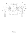
FIG. 2 illustrates a cross-section view of an electro-mechanical actuator in accordance with various embodiments; -
FIG. 3 illustrates a cross-section view of a puck and endcap in accordance with various embodiments; -
FIG. 4A illustrates a cross-section view of a portion of a retaining ring in accordance with various embodiments; -
FIG. 4B illustrates a cross-section view of a portion of an unbent retaining ring in accordance with various embodiments; -
FIG. 4C illustrates a cross-section view of a bent retaining ring in accordance with various embodiments; and -
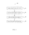
FIG. 5 illustrates a flow chart of a process for assembling an EMA in accordance with various embodiments. - The detailed description of exemplary embodiments herein makes reference to the accompanying drawings, which show various embodiments by way of illustration. While these various embodiments are described in sufficient detail to enable those skilled in the art to practice the disclosure, it should be understood that other embodiments may be realized and that logical changes and adaptations in design and construction may be made in accordance with this disclosure and the teachings herein. Thus, the detailed description herein is presented for purposes of illustration only and not of limitation. The scope of the disclosure is defined by the appended claims. For example, the steps recited in any of the method or process descriptions may be executed in any order and are not necessarily limited to the order presented. Furthermore, any reference to singular includes plural embodiments, and any reference to more than one component or step may include a singular embodiment or step. Also, any reference to attached, fixed, connected or the like may include permanent, removable, temporary, partial, full and/or any other possible attachment option. Additionally, any reference to without contact (or similar phrases) may also include reduced contact or minimal contact.
- In various embodiments, an aircraft brake system may comprise an electro-mechanical actuator. The electro-mechanical actuator may comprise a ball screw and a ball nut piston. The ball screw may rotate in order to drive the ball nut piston in an axial direction. An endcap may be welded to the ball nut piston. A split retaining ring may be welded to the endcap and around a base of the puck. The split retaining ring may prevent removal of the puck from the endcap. Thus, the puck may be prevented from unintentionally separating from the endcap.
- Referring to
FIG. 1 , a perspective view of a prior art electro-mechanical actuator ("EMA") 100 is illustrated according to various embodiments. Apuck 110 may be inserted into anendcap 160. Thepuck 110 may be pressed in by hand until thepuck 110 snaps into place. Aretention spring 115 may circumscribe abase 114 of thepuck 110. Theretention spring 115 may increase the amount of force necessary to remove thepuck 110 from theendcap 160. However, the force may still be relatively small, such that thepuck 110 may be susceptible to unintentionally separating from theendcap 160 due to vibrations or ice build-up around thepuck 110. - Referring to
FIG. 2 , a cross-section view of an electro-mechanical actuator ("EMA") 200 is illustrated according to various embodiments. The EMA 200 may extend along the axis marked A-A', with A being located near a distal portion of EMA 200 and A' being near a proximal portion of EMA 200. The EMA 200 may, as described above, be involved in the application of a braking force to an aircraft wheel. The EMA 200 assembly may comprise an EMAhousing 201, which may extend along the axis A-A'. The EMAhousing 201 may house a variety of components, including, for example, aball nut piston 250, aball screw 220, and an actuator drive unit ("ADU") 230. The ADU 230 may be located within an ADUhousing 231. Generally, the ADU 230 may rotate and may drive the ball screw 220 through a plurality of rotations. - As the
ball screw 220 rotates, theball nut piston 250 may translate distally and/or proximally along the axis A-A' (depending upon the direction of rotation of the ball screw 220). Anendcap 260 may be coupled to theball nut piston 250 at a distal end thereof. Theendcap 260 may be welded to theball nut piston 250. Apuck 210 may be adjacent to theendcap 260. A retainingring 240 may be coupled to theendcap 260 around abase 214 of thepuck 210. The retainingring 240 may be welded or riveted to theendcap 260. In various embodiments, the retainingring 240 may comprise a split ring comprising a first half and a second half. Thepuck 210 may exert a pressure against a brake stack coupled to an aircraft wheel to impede or halt a rotation of the wheel. The retainingring 240 may prevent removal of thepuck 210. Thus, thepuck 210 may be permanently retained within the retainingring 240. As used herein, "permanently retained" refers to a puck that may not be removed without damaging or de-assembling another component (e.g. damaging the retainingring 240, breaking a weld, removing a bolt, etc.) as opposed to a puck which may be removed without damaging any component by applying a force on the puck. - Referring to
FIG. 3 , a cross-section view of thepuck 210 andendcap 260 is illustrated according to various embodiments. Theendcap 260 may be coupled to theball nut piston 250. In various embodiments, theendcap 260 may be welded to theball nut piston 250 with aweld 332. Theendcap 260 may generally be in the shape of a disk having aconvex dome 362 in the center of the disk. - The
puck 210 may comprise acontact plate 312. Thecontact plate 312 may be configured to contact a brake stack to apply braking force to an aircraft. Thepuck 210 may comprise a base 214 located adjacent to theconvex dome 362. The base 214 may comprise aconcave surface 316. Theconcave surface 316 may allow thepuck 210 to pivot about theconvex dome 362. A pivoting motion may facilitate in keeping thefull contact plate 312 in contact with a brake stack. A diameter D1 of thebase 214 of thepuck 210 may be greater than a diameter D2 of aneck 318 between the base 214 and thecontact plate 312. - A retaining
ring 240 may be coupled to theendcap 260. In various embodiments, the retainingring 240 may be welded to theendcap 260 via aweld 333. The retainingring 240 may be welded to theendcap 260 at or near the same time that theendcap 260 is welded to theball nut piston 250. However, the retainingring 240 may be coupled to theendcap 260 by any suitable process, such as riveting, bolting, bonding, etc. In various embodiments, the retainingring 240 may comprise a split ring, wherein the retainingring 240 comprises afirst half 341 and asecond half 342. However, in various embodiments, the retainingring 240 may comprise a single piece, and a portion of the retainingring 240 may be bent after installation of thepuck 210 in order to retain thepuck 210 within the retainingring 240. A diameter D3 of alip 343 of the retainingring 240 may be greater than the diameter D2 of theneck 318, and less than the diameter D1 of thebase 214. Thus, the retainingring 240 may prevent thepuck 210 from separating from theendcap 260. - Referring to
FIG. 4A , a cross-section of a portion of a retainingring 240 is illustrated according to various embodiments. The retainingring 240 may comprise a base 444 coupled to anendcap 260. A retainingring wall 445 may extend from the base 444 away from theendcap 260. Alip 447 extending from the retainingring wall 445 may overlap thebase 214 of a puck, such that the puck is retained within the retainingring 240. In various embodiments, the retainingring 240 may be a split ring which is coupled to theendcap 260 after thebase 214 of the puck is placed adjacent to theendcap 260. - A gap G may be present between the base 214 of the puck and the
lip 447 of the retainingring 240. The gap G may provide freedom of motion for thebase 214 of the puck, allowing the puck to pivot within the retainingring 240. In various embodiments, a spring or other component may be placed between the base 214 and the retainingring 240 to provide damping while still allowing the puck to pivot within the retainingring 240. - Referring to
FIG. 4B and 4C , an integral retaining ring is illustrated according to various embodiments. InFIG. 4B , the retainingring 440 is illustrated prior to a lip being formed. InFIG. 4C , the retainingring 440 is illustrated after a lip is formed. In various embodiments, a retainingring 440 may be an integral component, such that the retainingring 440 is a single continuous ring. In such embodiments, thelip 448 may not be present when the retainingring 440 is coupled to theendcap 260. The retainingring 440 may be coupled to theendcap 260 before the puck is positioned next to theendcap 260. Thebase 214 of the puck may be positioned within the retainingring 440, and thelip 448 may be formed by bending a portion of the retainingring wall 446 such that a bent portion of the retainingring wall 446 forms thelip 448 and overlaps thebase 214 of the puck. In various embodiments, thelip 448 may be bent to be perpendicular with the retainingring wall 446. However, thelip 448 may be bent to any suitable angle with respect to the retainingring wall 446 such that thelip 448 overlaps thebase 214 of the puck. - Referring to
FIG. 5 , aflow chart 500 of a method for installing a puck is illustrated according to various embodiments. An endcap may be coupled to a ball nut piston (step 510). In various embodiments, the endcap may be welded to the ball nut piston. A puck may be positioned adjacent to the endcap (step 520). A retaining ring may be coupled to the endcap (step 530). The puck may be secured within the retaining ring (step 540). The puck may be permanently retained within the retaining ring. In various embodiments, securing the puck within the retaining ring may comprise coupling a first half of the retaining ring and a second half of the retaining ring to the endcap and around a base of the puck. However, in various embodiments, securing the puck within the retaining ring may comprise coupling the retaining ring to the endcap, inserting the base of the puck within the retaining ring, and then bending the retaining ring over the base of the puck. In various embodiments, the retaining ring may be welded, riveted, bolted, and/or bonded to the endcap. - Benefits, other advantages, and solutions to problems have been described herein with regard to specific embodiments. Furthermore, the connecting lines shown in the various figures contained herein are intended to represent exemplary functional relationships and/or physical couplings between the various elements. It should be noted that many alternative or additional functional relationships or physical connections may be present in a practical system. However, the benefits, advantages, solutions to problems, and any elements that may cause any benefit, advantage, or solution to occur or become more pronounced are not to be construed as critical, required, or essential features or elements of the disclosure. The scope of the disclosure is accordingly to be limited by nothing other than the appended claims, in which reference to an element in the singular is not intended to mean "one and only one" unless explicitly so stated, but rather "one or more." Moreover, where a phrase similar to "at least one of A, B, or C" is used in the claims, it is intended that the phrase be interpreted to mean that A alone may be present in an embodiment, B alone may be present in an embodiment, C alone may be present in an embodiment, or that any combination of the elements A, B and C may be present in a single embodiment; for example, A and B, A and C, B and C, or A and B and C.
- Systems, methods and apparatus are provided herein. In the detailed description herein, references to "various embodiments", "one embodiment", "an embodiment", "an example embodiment", etc., indicate that the embodiment described may include a particular feature, structure, or characteristic, but every embodiment may not necessarily include the particular feature, structure, or characteristic. Moreover, such phrases are not necessarily referring to the same embodiment. Further, when a particular feature, structure, or characteristic is described in connection with an embodiment, it is submitted that it is within the knowledge of one skilled in the art to affect such feature, structure, or characteristic in connection with other embodiments whether or not explicitly described. After reading the description, it will be apparent to one skilled in the relevant art(s) how to implement the disclosure in alternative embodiments.
- Furthermore, no element, component, or method step in the present disclosure is intended to be dedicated to the public regardless of whether the element, component, or method step is explicitly recited in the claims. No claim element herein is to be construed under the provisions of 35 U.S.C. 112(f), unless the element is expressly recited using the phrase "means for." As used herein, the terms "comprises", "comprising", or any other variation thereof, are intended to cover a non-exclusive inclusion, such that a process, method, article, or apparatus that comprises a list of elements does not include only those elements but may include other elements not expressly listed or inherent to such process, method, article, or apparatus.
Claims (15)
- An electro-mechanical actuator ("EMA") (200) comprising:a ball nut piston (250);an endcap (260) coupled to the ball nut piston (250);a retaining ring (240; 440) coupled to the endcap (260); anda puck (210) comprising a contact plate (312) and a base (214), wherein the base (214) is located within the retaining ring (240; 440), and wherein a diameter (D1) of the base (214) is greater than a diameter (D3) of a lip (343; 447; 448) of the retaining ring (240; 440).
- The EMA of claim 1, wherein the retaining ring (240; 440) comprises a split ring (341, 342).
- The EMA of claim 2, wherein the split ring (341, 342) is welded to the endcap.
- The EMA of claim 1, 2 or 3, wherein the puck (210) is permanently retained within the retaining ring (240; 440).
- The EMA of any preceding claim, wherein the endcap (260) is welded to the ball nut piston (250).
- The EMA of any preceding claim, wherein the lip (343; 447; 448) comprises a bent portion of the retaining ring (240; 440).
- The EMA of any preceding claim, wherein the retaining ring (240; 440) is an integral component.
- The EMA of any preceding claim, wherein the diameter (D3) of the lip (343; 447; 448) is greater than a diameter (D2) of a neck (318) of the puck (210).
- The EMA of any preceding claim, further comprising a gap (G) between the base (214) and the lip (343; 447; 448).
- A method of assembling an electro-mechanical actuator ("EMA") (200) comprising:coupling an endcap (260) to a ball nut piston (250);positioning a puck (210) adjacent to the endcap (260);coupling a retaining ring (240; 440) to the endcap (260); andpermanently securing the puck (210) within the retaining ring (240; 440).
- The method of claim 10, further comprising inserting the puck (210) within the retaining ring (240; 440).
- The method of claim 10 or 11, further comprising bending the retaining ring (240; 440) to form a lip (343; 447, 448).
- The method of claim 10, 11 or 12, wherein the retaining ring (240; 440) comprises a split ring (341, 342), and wherein the coupling the retaining ring (240; 440) comprises coupling a first half (341) of the retaining ring (240; 440) to the endcap (260) and coupling a second half (342) of the retaining ring (240; 440).
- The method of any of claims 10 to 13, wherein the retaining ring (240; 440) comprises a/the split ring (341, 342), and wherein the retaining ring (240; 440) is coupled to the endcap (260) after the puck (210) is positioned adjacent to the endcap (260).
- The method of claim 10, 11 or 12, wherein the retaining ring (240; 440) is an integral component, and wherein the retaining ring (240; 440) is coupled to the endcap (260) before the puck (210) is positioned adjacent to the endcap (260).
Applications Claiming Priority (1)
| Application Number | Priority Date | Filing Date | Title |
|---|---|---|---|
| US14/531,648 US9926073B2 (en) | 2014-11-03 | 2014-11-03 | Aircraft brake puck assembly |
Publications (2)
| Publication Number | Publication Date |
|---|---|
| EP3020999A1 true EP3020999A1 (en) | 2016-05-18 |
| EP3020999B1 EP3020999B1 (en) | 2019-01-02 |
Family
ID=54427594
Family Applications (1)
| Application Number | Title | Priority Date | Filing Date |
|---|---|---|---|
| EP15192699.5A Active EP3020999B1 (en) | 2014-11-03 | 2015-11-03 | Aircraft brake puck assembly |
Country Status (2)
| Country | Link |
|---|---|
| US (1) | US9926073B2 (en) |
| EP (1) | EP3020999B1 (en) |
Families Citing this family (5)
| Publication number | Priority date | Publication date | Assignee | Title |
|---|---|---|---|---|
| US9562579B2 (en) * | 2014-10-29 | 2017-02-07 | Goodrich Corporation | Vented EMA with desiccant |
| US10830321B2 (en) * | 2016-02-19 | 2020-11-10 | Goodrich Corporation | Actuator ball screw for improved load sharing |
| US10106139B2 (en) | 2017-02-02 | 2018-10-23 | Goodrich Corporation | Brake systems and methods |
| US12078219B2 (en) * | 2021-05-14 | 2024-09-03 | Hl Mando Corporation | Articulating brake piston junction |
| DE102024204148A1 (en) | 2024-05-03 | 2025-11-06 | Robert Bosch Gesellschaft mit beschränkter Haftung | Compensating plate for an electromechanical brake |
Citations (3)
| Publication number | Priority date | Publication date | Assignee | Title |
|---|---|---|---|---|
| DE1257603B (en) * | 1964-08-07 | 1967-12-28 | Rech Etudes Prod | Mechanical actuation device for disc brakes, especially for motor vehicles |
| EP0480358A1 (en) * | 1990-10-09 | 1992-04-15 | The B.F. Goodrich Company | Aircraft brake |
| US20050167211A1 (en) * | 2004-02-03 | 2005-08-04 | Hageman John B. | Electric brake caliper with load equalization |
Family Cites Families (28)
| Publication number | Priority date | Publication date | Assignee | Title |
|---|---|---|---|---|
| USRE24870E (en) * | 1952-11-11 | 1960-09-20 | Vehicle brake | |
| US2937722A (en) * | 1956-09-11 | 1960-05-24 | Bendix Aviat Corp | Disk brakes |
| DE1475497B2 (en) * | 1965-08-14 | 1973-02-01 | Alfred Teves Gmbh, 6000 Fankfurt | PRESSURE-ACTUATED PARTIAL-LADING DISC BRAKE |
| BE695079A (en) * | 1967-03-06 | 1967-08-14 | ||
| US4036330A (en) * | 1974-12-18 | 1977-07-19 | The B. F. Goodrich Company | Disc brake |
| US4359976A (en) * | 1980-06-17 | 1982-11-23 | Steele Harry C | Compression compensator |
| US4781272A (en) * | 1983-08-31 | 1988-11-01 | Rockwell International Corporation | Friction pad and support for a disc brake |
| DE4121054A1 (en) * | 1991-06-26 | 1993-01-07 | Teves Gmbh Alfred | PRESSURE-CONTROLLED ADJUSTMENT FOR A VEHICLE BRAKE |
| DE4127030A1 (en) * | 1991-08-16 | 1993-02-18 | Fichtel & Sachs Ag | DRIVE HUB WITH CONTINUOUSLY ADJUSTABLE GEAR RATIO |
| EP1038118B1 (en) * | 1997-12-16 | 2003-06-11 | BPW Bergische Achsen Kommanditgesellschaft | Braking device |
| NL1010576C2 (en) * | 1998-11-17 | 2000-05-18 | Skf Eng & Res Centre Bv | Screw actuator, comprising a multifunctional sleeve and a claw. |
| NL1010575C2 (en) * | 1998-11-17 | 2000-05-18 | Skf Eng & Res Centre Bv | Screw actuator with lubricant dosage, and caliper. |
| US6125973A (en) * | 1998-12-29 | 2000-10-03 | Irvine; Mark W. | Brake pad holder |
| NL1013651C2 (en) * | 1999-11-23 | 2001-05-28 | Skf Eng & Res Centre Bv | Actuator with compensation of alignment differences. |
| US6412610B1 (en) * | 1999-11-24 | 2002-07-02 | Delphi Technologies, Inc. | Electric brake caliper |
| US7066304B2 (en) * | 1999-12-02 | 2006-06-27 | Haldex Brake Products Ab | Disc brake |
| US6554542B2 (en) * | 2000-04-10 | 2003-04-29 | Shimizu Construction Co., Ltd. | Stress transmission device, and structure and method of constructing the same |
| US6209582B1 (en) * | 2000-05-26 | 2001-04-03 | Honeywell Commercial Vehicle Systems Company | 2-way collar and O-ring seal assembly |
| US6484469B2 (en) * | 2000-10-19 | 2002-11-26 | William E. Drake | Column structures and methods for supporting compressive loads |
| EP1391628B1 (en) * | 2002-08-06 | 2009-12-16 | Meritor Heavy Vehicle Braking Systems (UK) Limited | Brake pad and brake caliper for disc brakes |
| US20040040797A1 (en) * | 2002-08-30 | 2004-03-04 | Plude Leo W. | Electromechanical aircraft brake system and method incorporating piezoelectric actuator subsystem |
| ITTO20021103A1 (en) * | 2002-12-20 | 2004-06-21 | Skf Ind Spa | ELECTROMECHANICAL SCREW ACTUATOR GROUP |
| US7344006B2 (en) * | 2004-03-03 | 2008-03-18 | Goodrich Corporation | Piston assembly for use in a brake assembly |
| US6991074B1 (en) * | 2005-02-17 | 2006-01-31 | Robert Bosch Gmbh | Disc Brake |
| US7565953B2 (en) * | 2006-05-11 | 2009-07-28 | Meggitt Aircraft Braking Systems | Brake force transducer for electric brakes |
| US8613683B2 (en) * | 2009-04-15 | 2013-12-24 | Srinivas R. Bidare | Pneumato-mechanical regenerative power source |
| JP5596575B2 (en) * | 2011-01-21 | 2014-09-24 | Ntn株式会社 | Electric linear actuator and electric disc brake device |
| FR2999257B1 (en) * | 2012-12-12 | 2015-01-02 | Chassis Brakes Int Bv | "DISC BRAKE WITH PARKING BRAKE, MECHANICAL PUSH ASSEMBLY, AND MOUNTING METHOD" |
-
2014
- 2014-11-03 US US14/531,648 patent/US9926073B2/en active Active
-
2015
- 2015-11-03 EP EP15192699.5A patent/EP3020999B1/en active Active
Patent Citations (3)
| Publication number | Priority date | Publication date | Assignee | Title |
|---|---|---|---|---|
| DE1257603B (en) * | 1964-08-07 | 1967-12-28 | Rech Etudes Prod | Mechanical actuation device for disc brakes, especially for motor vehicles |
| EP0480358A1 (en) * | 1990-10-09 | 1992-04-15 | The B.F. Goodrich Company | Aircraft brake |
| US20050167211A1 (en) * | 2004-02-03 | 2005-08-04 | Hageman John B. | Electric brake caliper with load equalization |
Also Published As
| Publication number | Publication date |
|---|---|
| US20160122009A1 (en) | 2016-05-05 |
| EP3020999B1 (en) | 2019-01-02 |
| US9926073B2 (en) | 2018-03-27 |
Similar Documents
| Publication | Publication Date | Title |
|---|---|---|
| EP3020999B1 (en) | Aircraft brake puck assembly | |
| EP3327308B1 (en) | Brake system with bridged clip retainer | |
| JP6267325B2 (en) | Jig for temporary assembly tool | |
| US10436265B2 (en) | Rivet-less rotor clip design | |
| US10578198B2 (en) | Ball screw assembly for aircraft brake | |
| WO2018126044A1 (en) | Floating rotor disc brake with marcel expander ring attachment | |
| EP3540259B1 (en) | Torque button lock clip | |
| EP3023648B1 (en) | Clip for pin retention | |
| EP2891829A2 (en) | Electromechanical actuator proximal position stopping assembly | |
| EP2842822B1 (en) | Ball screw and electromechanical actuator with such ball screw | |
| US11698085B2 (en) | Rod end cover | |
| US9360095B2 (en) | Electromechanical actuator distal position stopping assembly | |
| EP3587140B1 (en) | Torque bar retention for wheel assemblies | |
| US9272570B2 (en) | Integral clamp hubcap for wheel system and apparatus | |
| JP6581640B2 (en) | How to remove the branch structure | |
| EP3404283A1 (en) | Extended torque tube | |
| EP3715244B1 (en) | Bolted joint for wheel assemblies | |
| US9511876B2 (en) | Actuator housing for ram air turbine deployment actuator | |
| EP1844951A1 (en) | Self-locking nipple and wheel spoke | |
| KR20170062920A (en) | A drain bolt capable collecting of metal waste | |
| CN120917260A (en) | Cutting sleeve type connecting device | |
| EP3184323A2 (en) | Brake axle sleeve |
Legal Events
| Date | Code | Title | Description |
|---|---|---|---|
| PUAI | Public reference made under article 153(3) epc to a published international application that has entered the european phase |
Free format text: ORIGINAL CODE: 0009012 |
|
| AK | Designated contracting states |
Kind code of ref document: A1 Designated state(s): AL AT BE BG CH CY CZ DE DK EE ES FI FR GB GR HR HU IE IS IT LI LT LU LV MC MK MT NL NO PL PT RO RS SE SI SK SM TR |
|
| AX | Request for extension of the european patent |
Extension state: BA ME |
|
| STAA | Information on the status of an ep patent application or granted ep patent |
Free format text: STATUS: REQUEST FOR EXAMINATION WAS MADE |
|
| 17P | Request for examination filed |
Effective date: 20161110 |
|
| RBV | Designated contracting states (corrected) |
Designated state(s): AL AT BE BG CH CY CZ DE DK EE ES FI FR GB GR HR HU IE IS IT LI LT LU LV MC MK MT NL NO PL PT RO RS SE SI SK SM TR |
|
| GRAP | Despatch of communication of intention to grant a patent |
Free format text: ORIGINAL CODE: EPIDOSNIGR1 |
|
| STAA | Information on the status of an ep patent application or granted ep patent |
Free format text: STATUS: GRANT OF PATENT IS INTENDED |
|
| RIC1 | Information provided on ipc code assigned before grant |
Ipc: F16D 65/18 20060101AFI20180423BHEP |
|
| INTG | Intention to grant announced |
Effective date: 20180522 |
|
| GRAS | Grant fee paid |
Free format text: ORIGINAL CODE: EPIDOSNIGR3 |
|
| GRAA | (expected) grant |
Free format text: ORIGINAL CODE: 0009210 |
|
| STAA | Information on the status of an ep patent application or granted ep patent |
Free format text: STATUS: THE PATENT HAS BEEN GRANTED |
|
| AK | Designated contracting states |
Kind code of ref document: B1 Designated state(s): AL AT BE BG CH CY CZ DE DK EE ES FI FR GB GR HR HU IE IS IT LI LT LU LV MC MK MT NL NO PL PT RO RS SE SI SK SM TR |
|
| REG | Reference to a national code |
Ref country code: GB Ref legal event code: FG4D |
|
| REG | Reference to a national code |
Ref country code: CH Ref legal event code: EP Ref country code: AT Ref legal event code: REF Ref document number: 1084770 Country of ref document: AT Kind code of ref document: T Effective date: 20190115 |
|
| REG | Reference to a national code |
Ref country code: IE Ref legal event code: FG4D |
|
| REG | Reference to a national code |
Ref country code: DE Ref legal event code: R096 Ref document number: 602015022656 Country of ref document: DE |
|
| REG | Reference to a national code |
Ref country code: NL Ref legal event code: MP Effective date: 20190102 |
|
| REG | Reference to a national code |
Ref country code: LT Ref legal event code: MG4D |
|
| REG | Reference to a national code |
Ref country code: AT Ref legal event code: MK05 Ref document number: 1084770 Country of ref document: AT Kind code of ref document: T Effective date: 20190102 |
|
| PG25 | Lapsed in a contracting state [announced via postgrant information from national office to epo] |
Ref country code: NL Free format text: LAPSE BECAUSE OF FAILURE TO SUBMIT A TRANSLATION OF THE DESCRIPTION OR TO PAY THE FEE WITHIN THE PRESCRIBED TIME-LIMIT Effective date: 20190102 |
|
| PG25 | Lapsed in a contracting state [announced via postgrant information from national office to epo] |
Ref country code: NO Free format text: LAPSE BECAUSE OF FAILURE TO SUBMIT A TRANSLATION OF THE DESCRIPTION OR TO PAY THE FEE WITHIN THE PRESCRIBED TIME-LIMIT Effective date: 20190402 Ref country code: PL Free format text: LAPSE BECAUSE OF FAILURE TO SUBMIT A TRANSLATION OF THE DESCRIPTION OR TO PAY THE FEE WITHIN THE PRESCRIBED TIME-LIMIT Effective date: 20190102 Ref country code: SE Free format text: LAPSE BECAUSE OF FAILURE TO SUBMIT A TRANSLATION OF THE DESCRIPTION OR TO PAY THE FEE WITHIN THE PRESCRIBED TIME-LIMIT Effective date: 20190102 Ref country code: FI Free format text: LAPSE BECAUSE OF FAILURE TO SUBMIT A TRANSLATION OF THE DESCRIPTION OR TO PAY THE FEE WITHIN THE PRESCRIBED TIME-LIMIT Effective date: 20190102 Ref country code: PT Free format text: LAPSE BECAUSE OF FAILURE TO SUBMIT A TRANSLATION OF THE DESCRIPTION OR TO PAY THE FEE WITHIN THE PRESCRIBED TIME-LIMIT Effective date: 20190502 Ref country code: ES Free format text: LAPSE BECAUSE OF FAILURE TO SUBMIT A TRANSLATION OF THE DESCRIPTION OR TO PAY THE FEE WITHIN THE PRESCRIBED TIME-LIMIT Effective date: 20190102 Ref country code: LT Free format text: LAPSE BECAUSE OF FAILURE TO SUBMIT A TRANSLATION OF THE DESCRIPTION OR TO PAY THE FEE WITHIN THE PRESCRIBED TIME-LIMIT Effective date: 20190102 |
|
| PG25 | Lapsed in a contracting state [announced via postgrant information from national office to epo] |
Ref country code: LV Free format text: LAPSE BECAUSE OF FAILURE TO SUBMIT A TRANSLATION OF THE DESCRIPTION OR TO PAY THE FEE WITHIN THE PRESCRIBED TIME-LIMIT Effective date: 20190102 Ref country code: HR Free format text: LAPSE BECAUSE OF FAILURE TO SUBMIT A TRANSLATION OF THE DESCRIPTION OR TO PAY THE FEE WITHIN THE PRESCRIBED TIME-LIMIT Effective date: 20190102 Ref country code: GR Free format text: LAPSE BECAUSE OF FAILURE TO SUBMIT A TRANSLATION OF THE DESCRIPTION OR TO PAY THE FEE WITHIN THE PRESCRIBED TIME-LIMIT Effective date: 20190403 Ref country code: IS Free format text: LAPSE BECAUSE OF FAILURE TO SUBMIT A TRANSLATION OF THE DESCRIPTION OR TO PAY THE FEE WITHIN THE PRESCRIBED TIME-LIMIT Effective date: 20190502 Ref country code: BG Free format text: LAPSE BECAUSE OF FAILURE TO SUBMIT A TRANSLATION OF THE DESCRIPTION OR TO PAY THE FEE WITHIN THE PRESCRIBED TIME-LIMIT Effective date: 20190402 Ref country code: RS Free format text: LAPSE BECAUSE OF FAILURE TO SUBMIT A TRANSLATION OF THE DESCRIPTION OR TO PAY THE FEE WITHIN THE PRESCRIBED TIME-LIMIT Effective date: 20190102 |
|
| REG | Reference to a national code |
Ref country code: DE Ref legal event code: R097 Ref document number: 602015022656 Country of ref document: DE |
|
| PG25 | Lapsed in a contracting state [announced via postgrant information from national office to epo] |
Ref country code: AT Free format text: LAPSE BECAUSE OF FAILURE TO SUBMIT A TRANSLATION OF THE DESCRIPTION OR TO PAY THE FEE WITHIN THE PRESCRIBED TIME-LIMIT Effective date: 20190102 Ref country code: DK Free format text: LAPSE BECAUSE OF FAILURE TO SUBMIT A TRANSLATION OF THE DESCRIPTION OR TO PAY THE FEE WITHIN THE PRESCRIBED TIME-LIMIT Effective date: 20190102 Ref country code: EE Free format text: LAPSE BECAUSE OF FAILURE TO SUBMIT A TRANSLATION OF THE DESCRIPTION OR TO PAY THE FEE WITHIN THE PRESCRIBED TIME-LIMIT Effective date: 20190102 Ref country code: SK Free format text: LAPSE BECAUSE OF FAILURE TO SUBMIT A TRANSLATION OF THE DESCRIPTION OR TO PAY THE FEE WITHIN THE PRESCRIBED TIME-LIMIT Effective date: 20190102 Ref country code: RO Free format text: LAPSE BECAUSE OF FAILURE TO SUBMIT A TRANSLATION OF THE DESCRIPTION OR TO PAY THE FEE WITHIN THE PRESCRIBED TIME-LIMIT Effective date: 20190102 Ref country code: IT Free format text: LAPSE BECAUSE OF FAILURE TO SUBMIT A TRANSLATION OF THE DESCRIPTION OR TO PAY THE FEE WITHIN THE PRESCRIBED TIME-LIMIT Effective date: 20190102 Ref country code: CZ Free format text: LAPSE BECAUSE OF FAILURE TO SUBMIT A TRANSLATION OF THE DESCRIPTION OR TO PAY THE FEE WITHIN THE PRESCRIBED TIME-LIMIT Effective date: 20190102 Ref country code: AL Free format text: LAPSE BECAUSE OF FAILURE TO SUBMIT A TRANSLATION OF THE DESCRIPTION OR TO PAY THE FEE WITHIN THE PRESCRIBED TIME-LIMIT Effective date: 20190102 |
|
| PLBE | No opposition filed within time limit |
Free format text: ORIGINAL CODE: 0009261 |
|
| STAA | Information on the status of an ep patent application or granted ep patent |
Free format text: STATUS: NO OPPOSITION FILED WITHIN TIME LIMIT |
|
| PG25 | Lapsed in a contracting state [announced via postgrant information from national office to epo] |
Ref country code: SM Free format text: LAPSE BECAUSE OF FAILURE TO SUBMIT A TRANSLATION OF THE DESCRIPTION OR TO PAY THE FEE WITHIN THE PRESCRIBED TIME-LIMIT Effective date: 20190102 |
|
| 26N | No opposition filed |
Effective date: 20191003 |
|
| PG25 | Lapsed in a contracting state [announced via postgrant information from national office to epo] |
Ref country code: SI Free format text: LAPSE BECAUSE OF FAILURE TO SUBMIT A TRANSLATION OF THE DESCRIPTION OR TO PAY THE FEE WITHIN THE PRESCRIBED TIME-LIMIT Effective date: 20190102 |
|
| PG25 | Lapsed in a contracting state [announced via postgrant information from national office to epo] |
Ref country code: TR Free format text: LAPSE BECAUSE OF FAILURE TO SUBMIT A TRANSLATION OF THE DESCRIPTION OR TO PAY THE FEE WITHIN THE PRESCRIBED TIME-LIMIT Effective date: 20190102 |
|
| REG | Reference to a national code |
Ref country code: DE Ref legal event code: R119 Ref document number: 602015022656 Country of ref document: DE |
|
| REG | Reference to a national code |
Ref country code: CH Ref legal event code: PL |
|
| PG25 | Lapsed in a contracting state [announced via postgrant information from national office to epo] |
Ref country code: CH Free format text: LAPSE BECAUSE OF NON-PAYMENT OF DUE FEES Effective date: 20191130 Ref country code: LU Free format text: LAPSE BECAUSE OF NON-PAYMENT OF DUE FEES Effective date: 20191103 Ref country code: MC Free format text: LAPSE BECAUSE OF FAILURE TO SUBMIT A TRANSLATION OF THE DESCRIPTION OR TO PAY THE FEE WITHIN THE PRESCRIBED TIME-LIMIT Effective date: 20190102 Ref country code: LI Free format text: LAPSE BECAUSE OF NON-PAYMENT OF DUE FEES Effective date: 20191130 |
|
| REG | Reference to a national code |
Ref country code: BE Ref legal event code: MM Effective date: 20191130 |
|
| PG25 | Lapsed in a contracting state [announced via postgrant information from national office to epo] |
Ref country code: DE Free format text: LAPSE BECAUSE OF NON-PAYMENT OF DUE FEES Effective date: 20200603 Ref country code: IE Free format text: LAPSE BECAUSE OF NON-PAYMENT OF DUE FEES Effective date: 20191103 |
|
| PG25 | Lapsed in a contracting state [announced via postgrant information from national office to epo] |
Ref country code: BE Free format text: LAPSE BECAUSE OF NON-PAYMENT OF DUE FEES Effective date: 20191130 |
|
| PG25 | Lapsed in a contracting state [announced via postgrant information from national office to epo] |
Ref country code: CY Free format text: LAPSE BECAUSE OF FAILURE TO SUBMIT A TRANSLATION OF THE DESCRIPTION OR TO PAY THE FEE WITHIN THE PRESCRIBED TIME-LIMIT Effective date: 20190102 |
|
| PG25 | Lapsed in a contracting state [announced via postgrant information from national office to epo] |
Ref country code: MT Free format text: LAPSE BECAUSE OF FAILURE TO SUBMIT A TRANSLATION OF THE DESCRIPTION OR TO PAY THE FEE WITHIN THE PRESCRIBED TIME-LIMIT Effective date: 20190102 Ref country code: HU Free format text: LAPSE BECAUSE OF FAILURE TO SUBMIT A TRANSLATION OF THE DESCRIPTION OR TO PAY THE FEE WITHIN THE PRESCRIBED TIME-LIMIT; INVALID AB INITIO Effective date: 20151103 |
|
| PG25 | Lapsed in a contracting state [announced via postgrant information from national office to epo] |
Ref country code: MK Free format text: LAPSE BECAUSE OF FAILURE TO SUBMIT A TRANSLATION OF THE DESCRIPTION OR TO PAY THE FEE WITHIN THE PRESCRIBED TIME-LIMIT Effective date: 20190102 |
|
| P01 | Opt-out of the competence of the unified patent court (upc) registered |
Effective date: 20230522 |
|
| PGFP | Annual fee paid to national office [announced via postgrant information from national office to epo] |
Ref country code: GB Payment date: 20251023 Year of fee payment: 11 |
|
| PGFP | Annual fee paid to national office [announced via postgrant information from national office to epo] |
Ref country code: FR Payment date: 20251022 Year of fee payment: 11 |