EP3020666A1 - Sheet handling apparatus with rotary drum - Google Patents
Sheet handling apparatus with rotary drum Download PDFInfo
- Publication number
- EP3020666A1 EP3020666A1 EP15194824.7A EP15194824A EP3020666A1 EP 3020666 A1 EP3020666 A1 EP 3020666A1 EP 15194824 A EP15194824 A EP 15194824A EP 3020666 A1 EP3020666 A1 EP 3020666A1
- Authority
- EP
- European Patent Office
- Prior art keywords
- drum
- shutter member
- manifold
- openings
- air
- Prior art date
- Legal status (The legal status is an assumption and is not a legal conclusion. Google has not performed a legal analysis and makes no representation as to the accuracy of the status listed.)
- Granted
Links
Images




Classifications
-
- B—PERFORMING OPERATIONS; TRANSPORTING
- B65—CONVEYING; PACKING; STORING; HANDLING THIN OR FILAMENTARY MATERIAL
- B65H—HANDLING THIN OR FILAMENTARY MATERIAL, e.g. SHEETS, WEBS, CABLES
- B65H5/00—Feeding articles separated from piles; Feeding articles to machines
- B65H5/22—Feeding articles separated from piles; Feeding articles to machines by air-blast or suction device
- B65H5/222—Feeding articles separated from piles; Feeding articles to machines by air-blast or suction device by suction devices
- B65H5/226—Feeding articles separated from piles; Feeding articles to machines by air-blast or suction device by suction devices by suction rollers
-
- B—PERFORMING OPERATIONS; TRANSPORTING
- B65—CONVEYING; PACKING; STORING; HANDLING THIN OR FILAMENTARY MATERIAL
- B65H—HANDLING THIN OR FILAMENTARY MATERIAL, e.g. SHEETS, WEBS, CABLES
- B65H29/00—Delivering or advancing articles from machines; Advancing articles to or into piles
- B65H29/24—Delivering or advancing articles from machines; Advancing articles to or into piles by air blast or suction apparatus
- B65H29/241—Suction devices
- B65H29/243—Suction rollers
-
- B—PERFORMING OPERATIONS; TRANSPORTING
- B65—CONVEYING; PACKING; STORING; HANDLING THIN OR FILAMENTARY MATERIAL
- B65H—HANDLING THIN OR FILAMENTARY MATERIAL, e.g. SHEETS, WEBS, CABLES
- B65H29/00—Delivering or advancing articles from machines; Advancing articles to or into piles
- B65H29/54—Article strippers, e.g. for stripping from advancing elements
- B65H29/56—Article strippers, e.g. for stripping from advancing elements for stripping from elements or machines
-
- B—PERFORMING OPERATIONS; TRANSPORTING
- B65—CONVEYING; PACKING; STORING; HANDLING THIN OR FILAMENTARY MATERIAL
- B65H—HANDLING THIN OR FILAMENTARY MATERIAL, e.g. SHEETS, WEBS, CABLES
- B65H2301/00—Handling processes for sheets or webs
- B65H2301/30—Orientation, displacement, position of the handled material
- B65H2301/31—Features of transport path
- B65H2301/312—Features of transport path for transport path involving at least two planes of transport forming an angle between each other
- B65H2301/3122—U-shaped
-
- B—PERFORMING OPERATIONS; TRANSPORTING
- B65—CONVEYING; PACKING; STORING; HANDLING THIN OR FILAMENTARY MATERIAL
- B65H—HANDLING THIN OR FILAMENTARY MATERIAL, e.g. SHEETS, WEBS, CABLES
- B65H2301/00—Handling processes for sheets or webs
- B65H2301/40—Type of handling process
- B65H2301/44—Moving, forwarding, guiding material
- B65H2301/446—Assisting moving, forwarding or guiding of material
- B65H2301/4461—Assisting moving, forwarding or guiding of material by blowing air towards handled material
-
- B—PERFORMING OPERATIONS; TRANSPORTING
- B65—CONVEYING; PACKING; STORING; HANDLING THIN OR FILAMENTARY MATERIAL
- B65H—HANDLING THIN OR FILAMENTARY MATERIAL, e.g. SHEETS, WEBS, CABLES
- B65H2301/00—Handling processes for sheets or webs
- B65H2301/50—Auxiliary process performed during handling process
- B65H2301/51—Modifying a characteristic of handled material
- B65H2301/514—Modifying physical properties
- B65H2301/5143—Warming
-
- B—PERFORMING OPERATIONS; TRANSPORTING
- B65—CONVEYING; PACKING; STORING; HANDLING THIN OR FILAMENTARY MATERIAL
- B65H—HANDLING THIN OR FILAMENTARY MATERIAL, e.g. SHEETS, WEBS, CABLES
- B65H2301/00—Handling processes for sheets or webs
- B65H2301/50—Auxiliary process performed during handling process
- B65H2301/51—Modifying a characteristic of handled material
- B65H2301/514—Modifying physical properties
- B65H2301/5144—Cooling
-
- B—PERFORMING OPERATIONS; TRANSPORTING
- B65—CONVEYING; PACKING; STORING; HANDLING THIN OR FILAMENTARY MATERIAL
- B65H—HANDLING THIN OR FILAMENTARY MATERIAL, e.g. SHEETS, WEBS, CABLES
- B65H2401/00—Materials used for the handling apparatus or parts thereof; Properties thereof
- B65H2401/10—Materials
- B65H2401/15—Metals
-
- B—PERFORMING OPERATIONS; TRANSPORTING
- B65—CONVEYING; PACKING; STORING; HANDLING THIN OR FILAMENTARY MATERIAL
- B65H—HANDLING THIN OR FILAMENTARY MATERIAL, e.g. SHEETS, WEBS, CABLES
- B65H2406/00—Means using fluid
- B65H2406/30—Suction means
- B65H2406/33—Rotary suction means, e.g. roller, cylinder or drum
-
- B—PERFORMING OPERATIONS; TRANSPORTING
- B65—CONVEYING; PACKING; STORING; HANDLING THIN OR FILAMENTARY MATERIAL
- B65H—HANDLING THIN OR FILAMENTARY MATERIAL, e.g. SHEETS, WEBS, CABLES
- B65H2406/00—Means using fluid
- B65H2406/30—Suction means
- B65H2406/36—Means for producing, distributing or controlling suction
- B65H2406/361—Means for producing, distributing or controlling suction distributing vacuum from stationary element to movable element
- B65H2406/3612—Means for producing, distributing or controlling suction distributing vacuum from stationary element to movable element involving a shoe in sliding contact with flanges of a rotating element
-
- B—PERFORMING OPERATIONS; TRANSPORTING
- B65—CONVEYING; PACKING; STORING; HANDLING THIN OR FILAMENTARY MATERIAL
- B65H—HANDLING THIN OR FILAMENTARY MATERIAL, e.g. SHEETS, WEBS, CABLES
- B65H2406/00—Means using fluid
- B65H2406/30—Suction means
- B65H2406/36—Means for producing, distributing or controlling suction
- B65H2406/361—Means for producing, distributing or controlling suction distributing vacuum from stationary element to movable element
- B65H2406/3614—Means for producing, distributing or controlling suction distributing vacuum from stationary element to movable element involving a shoe in sliding contact with an inner section of the periphery of a rotating element
-
- B—PERFORMING OPERATIONS; TRANSPORTING
- B65—CONVEYING; PACKING; STORING; HANDLING THIN OR FILAMENTARY MATERIAL
- B65H—HANDLING THIN OR FILAMENTARY MATERIAL, e.g. SHEETS, WEBS, CABLES
- B65H2406/00—Means using fluid
- B65H2406/30—Suction means
- B65H2406/36—Means for producing, distributing or controlling suction
- B65H2406/362—Means for producing, distributing or controlling suction adjusting or controlling distribution of vacuum transversally to the transport direction, e.g. according to the width of material
- B65H2406/3622—Means for producing, distributing or controlling suction adjusting or controlling distribution of vacuum transversally to the transport direction, e.g. according to the width of material adjusting or controlling distribution of vacuum in the transport direction
-
- B—PERFORMING OPERATIONS; TRANSPORTING
- B65—CONVEYING; PACKING; STORING; HANDLING THIN OR FILAMENTARY MATERIAL
- B65H—HANDLING THIN OR FILAMENTARY MATERIAL, e.g. SHEETS, WEBS, CABLES
- B65H2406/00—Means using fluid
- B65H2406/30—Suction means
- B65H2406/36—Means for producing, distributing or controlling suction
- B65H2406/365—Means for producing, distributing or controlling suction selectively blowing or sucking
-
- B—PERFORMING OPERATIONS; TRANSPORTING
- B65—CONVEYING; PACKING; STORING; HANDLING THIN OR FILAMENTARY MATERIAL
- B65H—HANDLING THIN OR FILAMENTARY MATERIAL, e.g. SHEETS, WEBS, CABLES
- B65H2801/00—Application field
- B65H2801/03—Image reproduction devices
- B65H2801/06—Office-type machines, e.g. photocopiers
Definitions
- the invention relates to a sheet handling apparatus comprising:
- a sheet handling apparatus of this type has been described in JP 2010126269 A and may be used for conveying media sheets in a printer or copier, for example.
- the sheets are attracted to the peripheral wall of the drum and the drum rotates, the sheets are conveyed in circumferential direction of the drum.
- the heat conductivity of that wall may be utilized for controlling the temperature of the sheets, i.e. for heating or cooling them.
- the stationary shutter member has the purpose to interrupt the flow of air through the perforations at a specific angular position, so that the sheets can be detached from the drum more easily when they reach that position.
- the shutter member is a plate that is disposed inside the drum and is held in slide-sealing contact with the internal surface of the perforated peripheral wall, so that the perforations are covered and blocked by the plate when they move through the angular range where the plate is disposed.
- the known apparatus has the drawback that the seal between the shutter member and the peripheral wall of the drum will give rise to an increased frictional resistance and/or to an increased leakage of air.
- a segmented drum having a plurality of chambers distributed over the periphery of the drum, and a suction system that includes a plurality of valves for individually controlling the suction pressure in each of these chambers, so that the sheets can be released from the surface of the drum by closing the valves at appropriate timings.
- a suction system that includes a plurality of valves for individually controlling the suction pressure in each of these chambers, so that the sheets can be released from the surface of the drum by closing the valves at appropriate timings.
- the large number of valves leads to increased costs and an increased risk of failure.
- a rotary drum is generally formed of a solid material or a single 'block' of material.
- the separate chambers below the outer circumferential wall of the drum are then cut-out from said material, while channels are bored into the drum to provide air flow to said chambers.
- Such drums are generally heavy and their production is costly and lengthy. The weight is especially a drawback in an apparatus with a large drum, wherein the control of the large drum is difficult due the drum's large inertia. Further, the energy consumption for driving such a heavy drum is high.
- the apparatus of the type mentioned in the opening paragraph is characterized in that the number of separate chambers extend in axial direction from a first axial end of the drum to a second axial end of the drum and are distributed over the periphery of the drum, a disk-shaped manifold is mounted at the first axial end of the drum co-rotatably with the drum, which manifold forms a number of radial channels each of which has an outer end connected to one of said chambers and each of which has an opening at a radially inward end of each channel, and the stationary shutter member is arranged for blocking the opening of a channel to block air flow from a radially inward end of a channel to the suction system.
- the apparatus utilizes a segmented drum, but instead of having a plurality of valves, the suction system comprises a manifold mounted on an axial end of the drum, which manifold rotates together with the drum and forms a number of channels that extend radially inwardly from the respective chambers towards the axis of the drum.
- the shutter member is arranged to block openings at the inward ends of each channel and, consequently, is also disposed relatively close to the axis of the drum.
- the shutter member may be tightly sealed against the manifold without the energy losses caused by friction at the seal becoming too large.
- the dimensions of the seal are reduced, which further reduces the frictional forces, and the torque that is caused by these frictional forces and opposes the driving torque for the drum is reduced even more because the shorter radius at which the seal is disposed will reduce the leverage.
- the reduced dimensions of the shutter member and its seal will reduce the risk and/or amount of leakage.
- the invention has the further advantage that valve switching noises are avoided.
- the drum and the manifold may be formed of relatively thin or light weight materials, reducing the weight and costs of the apparatus.
- the reduced weight advantageously allows for an easier control of the drum as well as a reduction in energy consumption for driving the drum.
- the manifold may be formed separately from the drum and mounted onto the drum later to simplify the production of the apparatus.
- the manifold may be disposed inside of the drum and may extend over the entire length of the drum. In a preferred embodiment, however, the manifold and, consequently, also the shutter member are significantly smaller than the drum in axial direction, which helps to save costs and weight and to further reduce the amount of friction. If necessary, a plurality of manifolds may be distributed over the length of the drum, in order to assure a uniform evacuation of the chambers at the periphery of the drum.
- the manifold or manifolds are disposed outside of the drum at one or both axial ends thereof.
- the openings at the inner ends of the manifold channels may face in axial direction of the drum towards the mouth of a suction pipe leading to the suction system.
- the shutter member may simply be formed by a plate that extends in a plane normal to the axis of rotation of the drum and engages the internal part of the manifold where the openings of the channel are formed. For improved sealing, this plate may be biased elastically against the manifold.
- the shutter member may include an air supply system for introducing air into those channels of the manifold through which are to be shut-off. This permits to reduce a possible residual vacuum that could otherwise be caused by incomplete sealing between the channel openings and the suction system that must be connected to the openings of neighbouring channels.
- air may be blown actively into some of the manifold channels via the shutter member so as to actively blow-off the leading edges of the sheets from the surface of the drum.
- the openings at the radially inward ends of the channels are disposed adjacent an axis of the drum.
- the shutter member may be positioned adjacent and/or near an axis of the drum.
- the axis may be formed by a rotation axis of the drum, for example an axle.
- the shutter member may be disposed relatively close to or near by the axis of the drum, reducing frictional forces.
- the apparatus further comprises a ring element or ring extending circumferentially around an axis of the drum.
- Said ring preferably encloses the axis of the drum.
- the ring element comprises a substantially circumferentially extending window aligned with the openings at the radially inwards ends of the channels. Air may then pass from the openings through the window to e.g. a vaccum source.
- the window forms a circumferential passage or channel parallel to the drum axis, through which window air may flow.
- the window preferably substantially encloses the axis.
- the shutter member is positioned in the window and is thus arranged for blocking or closing an angular range of the window. The shutter member closes part of the window.
- the window defines a circumferential passage, wherein a predefined angular range of the window is closed or blocked by the shutter member.
- the window may, in an embodiment, extend around the axis for the majority of a turn, e.g. an almost complete turn, for example 350°. The remainder of the turn is occupied by the shutter member. For the remaining 10°, that region or part of the window is closed off by the shutter member.
- a angular region of the radially or circumferentially extending window is interrupted by the shutter member, locally preventing air flow.
- a drum according to the present invention may be provided on both sides of a disk-shaped manifold according to the present invention. Thereby, only a single manifold disk in between the two drums is required for supplying a suction force to both drums.
- an apparatus according to the present invention may be formed of multiple manifold disks and drums according to the present invention, which disks and drums are provided alternately in the axial direction of the drum.
- Fig. 1 shows a sheet handling apparatus which comprises a rotary drum 10 that has an outer peripheral wall 12 with perforations 14 formed therein.
- the drum 10 is mounted on a axle 16 that may be driven for rotation.
- the outer peripheral wall 12 together with an inner peripheral wall 18, delimits a number of chambers 20 that extend over the entire axial length of the drum.
- the channels 20 are distributed over the periphery of the drum 10 and are separated from one another by radial walls 22, as can be seen in Fig. 2 .
- a disk-like manifold 24 is attached to at least one axial end of the drum 10 and forms a plurality of radial channels 26 that connect each of the chambers 20 to a suction pipe 28 that, together with a blower 30, forms a suction system for drawing-in ambient air through the perforations 14 of the peripheral wall 12 of the drum.
- the sheet handling apparatus further comprises a pair of feed rollers 32 arranged to feed sheets 34, e.g. media sheets in a printer, onto the outer surface of the peripheral wall 12 of the drum 10, where the sheets are attracted by the air that is drawn in through the perforations 14.
- sheets 34 e.g. media sheets in a printer
- the drum 10 is made of a material with a high thermal conductivity, e.g. of metal, so that the sheets 34 may be cooled by dissipating heat via the drum.
- the suction effect should be removed or at least reduced in the angular range of the release position.
- a stationary shutter member 38 is disposed between an inner peripheral portion of the manifold 24 and the end of the suction pipe 28 in the angular range, where the suction effect is to be reduced.
- the manifold 24 is configured as a hollow disk with parallel end walls 40, 42, an outer peripheral wall 44 and an inner peripheral wall 46.
- the outer peripheral wall 44 is flanged to an end of the outer peripheral wall 12 of the drum 10, and the inner peripheral wall 46 connects the two end walls 40 and 42.
- the space between the end walls 40 and 42 is divided into the channels 26 by radial walls 48.
- the end wall 40 defines an opening 50 via which the corresponding channel can communicate with the interior of the suction pipe 28.
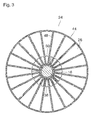
- some of the openings 50 in an angular range right below the axle 16 in Fig. 3 are blocked by the shutter member 38.
- the shutter member 38 forms part of a ring 52 that is biased against the end wall 40 of the manifold 24 by springs 54.
- a cylindrical part 56 of the ring 52 is sealed against the inner surface of the suction pipe 28 with an annular seal 58, and a flange part 60 of the ring 52 is sealed against the manifold 24 by two annular seals 62, 64 that are disposed radially outwardly and inwardly, respectively, of the corona of openings 50.
- Fig. 4 the seals 62 and 64 have been shown in phantom lines. These two seals are interconnected by radial seal strips 66 and 68 that seal against the shutter member 38 and delimit the angular range in which the air flow through the openings 50 is blocked.
- the shutter member 38 has a recessed part 70 facing the manifold 24.
- the plane (IV-IV) in which the sectional view in Fig. 4 is taken passes through the flange part 60 of the ring 52, some of the openings 50 are visible in Fig. 4 through the opening of the recessed part 70. Yet, as will be understood from Fig. 1 , these openings are blocked by the bottom of the recessed part 70.
- the ring 52 has arcuate windows 72 that are separated by narrow spokes 74 and establish fluid communication between the openings 50 of the manifold and the interior of the suction pipe 28.
- the recessed part 70 of the shutter member 38 is connected to a port 76 that permits to vent the interior of the recessed part 70 to the atmosphere. This will assure that no suction pressure is introduced into the channels 26 that are presently connected to the recessed part 70, even when the seals 62 and 64 do not completely seal this recessed part against the vacuum in the windows 72.
- a guide plate 78 is arranged to safely guide the separated sheet 34 into the nip between the rollers 36.
- Fig. 5 illustrates a modified embodiment having a manifold 24', wherein openings 50' that connect the channels 26 to a suction pipe 28' are formed in the inner peripheral wall 46 of the manifold.
- An end portion of the suction pipe 28' projects into the manifold and is sealed against the inner peripheral wall 46 with two seal rings 58' between which windows 72' are formed in the wall of the suction pipe 28.
- the shutter member 38' is simply formed by a part of the wall of the suction pipe 28' where the windows 72' have been omitted.
- This embodiment may be modified such that the axle 16 is omitted and the suction pipe 28' extends further into the drum 10 and serves as a shaft on which the manifold 24 and the drum 10 are rotatably supported.
- the manifold 24 could also be formed inside the drum 10, i.e. between the two axial ends thereof, or it might as well extend over the entire length of the drum 10, so that each chamber 20 would directly merge into the corresponding channel 26.
Landscapes
- Engineering & Computer Science (AREA)
- Mechanical Engineering (AREA)
- Feeding Of Articles By Means Other Than Belts Or Rollers (AREA)
- Delivering By Means Of Belts And Rollers (AREA)
- Sheets, Magazines, And Separation Thereof (AREA)
Abstract
Description
- The invention relates to a sheet handling apparatus comprising:
- a rotary drum having an outer peripheral wall with perforations formed therein, wherein the perforated wall of the drum delimits a number of separate chambers that extend inside the drum,
- a suction system for controlling a flow of air through the perforations of the drum, thereby to attract sheets to the peripheral wall of the drum; and
- a stationary shutter member for blocking the flow of air through the perforations when they pass, with the rotation of the drum, through a predetermined angular range.
- A sheet handling apparatus of this type has been described in
JP 2010126269 A - In the known apparatus, the shutter member is a plate that is disposed inside the drum and is held in slide-sealing contact with the internal surface of the perforated peripheral wall, so that the perforations are covered and blocked by the plate when they move through the angular range where the plate is disposed.
- When the dwell time of the sheets on the surface of the drum has to be extended in order to increase the time that is available for the heat exchange, it is necessary to increase the diameter of the drum. In that case, the known apparatus has the drawback that the seal between the shutter member and the peripheral wall of the drum will give rise to an increased frictional resistance and/or to an increased leakage of air.
- In an apparatus with a large drum, it has therefore been preferred to use a segmented drum having a plurality of chambers distributed over the periphery of the drum, and a suction system that includes a plurality of valves for individually controlling the suction pressure in each of these chambers, so that the sheets can be released from the surface of the drum by closing the valves at appropriate timings. However, the large number of valves leads to increased costs and an increased risk of failure.
- In the prior art, a rotary drum is generally formed of a solid material or a single 'block' of material. The separate chambers below the outer circumferential wall of the drum are then cut-out from said material, while channels are bored into the drum to provide air flow to said chambers. Such drums are generally heavy and their production is costly and lengthy. The weight is especially a drawback in an apparatus with a large drum, wherein the control of the large drum is difficult due the drum's large inertia. Further, the energy consumption for driving such a heavy drum is high.
- It is an object of the invention to provide a drum-type sheet handling apparatus that avoids the drawbacks of the prior art as discussed above.
- In order to achieve this object, according to the invention, the apparatus of the type mentioned in the opening paragraph is characterized in that the number of separate chambers extend in axial direction from a first axial end of the drum to a second axial end of the drum and are distributed over the periphery of the drum, a disk-shaped manifold is mounted at the first axial end of the drum co-rotatably with the drum, which manifold forms a number of radial channels each of which has an outer end connected to one of said chambers and each of which has an opening at a radially inward end of each channel, and the stationary shutter member is arranged for blocking the opening of a channel to block air flow from a radially inward end of a channel to the suction system.
- Thus, the apparatus according to the invention utilizes a segmented drum, but instead of having a plurality of valves, the suction system comprises a manifold mounted on an axial end of the drum, which manifold rotates together with the drum and forms a number of channels that extend radially inwardly from the respective chambers towards the axis of the drum. The shutter member is arranged to block openings at the inward ends of each channel and, consequently, is also disposed relatively close to the axis of the drum. As a result, the speed of the openings at the inner ends of the manifold channels relative to the stationary shutter member is significantly smaller than the speed with which the sheets are conveyed at the outer periphery of the drum. Consequently, the shutter member may be tightly sealed against the manifold without the energy losses caused by friction at the seal becoming too large. Moreover, as the shutter member is disposed at a relatively small radius, the dimensions of the seal are reduced, which further reduces the frictional forces, and the torque that is caused by these frictional forces and opposes the driving torque for the drum is reduced even more because the shorter radius at which the seal is disposed will reduce the leverage. In addition, the reduced dimensions of the shutter member and its seal will reduce the risk and/or amount of leakage.
- In comparison to an apparatus with a plurality of valves, the invention has the further advantage that valve switching noises are avoided.
- Additionally, by providing the disk-shaped manifold at an axial end of the drum, the drum and the manifold may be formed of relatively thin or light weight materials, reducing the weight and costs of the apparatus. The reduced weight advantageously allows for an easier control of the drum as well as a reduction in energy consumption for driving the drum. Further, in an apparatus according to the present invention the manifold may be formed separately from the drum and mounted onto the drum later to simplify the production of the apparatus.
- More specific optional features of the invention are indicated in the dependent claims.
- The manifold may be disposed inside of the drum and may extend over the entire length of the drum. In a preferred embodiment, however, the manifold and, consequently, also the shutter member are significantly smaller than the drum in axial direction, which helps to save costs and weight and to further reduce the amount of friction. If necessary, a plurality of manifolds may be distributed over the length of the drum, in order to assure a uniform evacuation of the chambers at the periphery of the drum.
- In another attractive embodiment, the manifold or manifolds are disposed outside of the drum at one or both axial ends thereof. In that case, the openings at the inner ends of the manifold channels may face in axial direction of the drum towards the mouth of a suction pipe leading to the suction system. Then, the shutter member may simply be formed by a plate that extends in a plane normal to the axis of rotation of the drum and engages the internal part of the manifold where the openings of the channel are formed. For improved sealing, this plate may be biased elastically against the manifold.
- According to a further development of the invention, the shutter member may include an air supply system for introducing air into those channels of the manifold through which are to be shut-off. This permits to reduce a possible residual vacuum that could otherwise be caused by incomplete sealing between the channel openings and the suction system that must be connected to the openings of neighbouring channels. Optionally, air may be blown actively into some of the manifold channels via the shutter member so as to actively blow-off the leading edges of the sheets from the surface of the drum.
- In an embodiment, the openings at the radially inward ends of the channels are disposed adjacent an axis of the drum. Further, the shutter member may be positioned adjacent and/or near an axis of the drum. The axis may be formed by a rotation axis of the drum, for example an axle. Thereby, the shutter member may be disposed relatively close to or near by the axis of the drum, reducing frictional forces.
- In an embodiment, the apparatus further comprises a ring element or ring extending circumferentially around an axis of the drum. Said ring preferably encloses the axis of the drum. The ring element comprises a substantially circumferentially extending window aligned with the openings at the radially inwards ends of the channels. Air may then pass from the openings through the window to e.g. a vaccum source. The window forms a circumferential passage or channel parallel to the drum axis, through which window air may flow. The window preferably substantially encloses the axis. The shutter member is positioned in the window and is thus arranged for blocking or closing an angular range of the window. The shutter member closes part of the window. Air is then able to flow through the passage of the window, except in the location where the shutter member has been provided. Basically, the window defines a circumferential passage, wherein a predefined angular range of the window is closed or blocked by the shutter member. The window may, in an embodiment, extend around the axis for the majority of a turn, e.g. an almost complete turn, for example 350°. The remainder of the turn is occupied by the shutter member. For the remaining 10°, that region or part of the window is closed off by the shutter member. As such, a angular region of the radially or circumferentially extending window is interrupted by the shutter member, locally preventing air flow.
- It will be appreciated that within the scope of the present invention a drum according to the present invention may be provided on both sides of a disk-shaped manifold according to the present invention. Thereby, only a single manifold disk in between the two drums is required for supplying a suction force to both drums. Further, an apparatus according to the present invention may be formed of multiple manifold disks and drums according to the present invention, which disks and drums are provided alternately in the axial direction of the drum.
- Embodiment examples will now be described in conjunction with the drawings, wherein:
- Fig. 1
- is a view of a sheet handling apparatus according to the invention in an axial sectional view;
- Fig. 2
- is a cross-sectional view taken along the line II-II in
Fig. 1 ; - Fig. 3
- is a cross-sectional view taken along the line III-III in
Fig. 1 ; - Fig. 4
- is a cross-sectional view taken along the line IV-IV in
Fig. 1 ; and - Fig. 5
- is an axial section, similar to
Fig. 1 , but illustrating a modified embodiment. -
Fig. 1 shows a sheet handling apparatus which comprises arotary drum 10 that has an outerperipheral wall 12 withperforations 14 formed therein. Thedrum 10 is mounted on aaxle 16 that may be driven for rotation. The outerperipheral wall 12 together with an innerperipheral wall 18, delimits a number ofchambers 20 that extend over the entire axial length of the drum. Thechannels 20 are distributed over the periphery of thedrum 10 and are separated from one another byradial walls 22, as can be seen inFig. 2 . - As is shown in
Fig. 1 , a disk-like manifold 24 is attached to at least one axial end of thedrum 10 and forms a plurality ofradial channels 26 that connect each of thechambers 20 to asuction pipe 28 that, together with ablower 30, forms a suction system for drawing-in ambient air through theperforations 14 of theperipheral wall 12 of the drum. - As has been illustrated in
Fig. 2 , the sheet handling apparatus further comprises a pair offeed rollers 32 arranged to feedsheets 34, e.g. media sheets in a printer, onto the outer surface of theperipheral wall 12 of thedrum 10, where the sheets are attracted by the air that is drawn in through theperforations 14. - As the
drum 10 rotates counter-clockwise inFig. 2 , thesheets 34 are conveyed around the drum while being held in intimate contact with theperipheral wall 12. - The
drum 10 is made of a material with a high thermal conductivity, e.g. of metal, so that thesheets 34 may be cooled by dissipating heat via the drum. The larger the diameter of thedrum 10, the more intense is the cooling effect that can be achieved for given conveying speed. - When the leading edge of a sheet reaches a release position, in this example at the lower apex of the drum, it is detached from the drum and conveyed further by means of another
roller pair 36. - In order for the
sheet 34 to be easily detached from the surface of theperipheral wall 12, the suction effect should be removed or at least reduced in the angular range of the release position. - To that end, as can be seen in
Fig. 1 , astationary shutter member 38 is disposed between an inner peripheral portion of the manifold 24 and the end of thesuction pipe 28 in the angular range, where the suction effect is to be reduced. - The manifold 24 is configured as a hollow disk with
parallel end walls 40, 42, an outerperipheral wall 44 and an innerperipheral wall 46. The outerperipheral wall 44 is flanged to an end of the outerperipheral wall 12 of thedrum 10, and the innerperipheral wall 46 connects the twoend walls 40 and 42. - As is shown in
Fig. 3 , the space between theend walls 40 and 42 is divided into thechannels 26 byradial walls 48. At the radially inward end of eachchannel 26, theend wall 40 defines anopening 50 via which the corresponding channel can communicate with the interior of thesuction pipe 28. However, some of theopenings 50 in an angular range right below theaxle 16 inFig. 3 are blocked by theshutter member 38. - Turning to
Fig. 1 again, theshutter member 38 forms part of aring 52 that is biased against theend wall 40 of the manifold 24 bysprings 54. Acylindrical part 56 of thering 52 is sealed against the inner surface of thesuction pipe 28 with anannular seal 58, and aflange part 60 of thering 52 is sealed against the manifold 24 by twoannular seals openings 50. - In
Fig. 4 , theseals shutter member 38 and delimit the angular range in which the air flow through theopenings 50 is blocked. - As can be seen in
Figs. 1 and4 , theshutter member 38 has a recessedpart 70 facing the manifold 24. As the plane (IV-IV) in which the sectional view inFig. 4 is taken passes through theflange part 60 of thering 52, some of theopenings 50 are visible inFig. 4 through the opening of the recessedpart 70. Yet, as will be understood fromFig. 1 , these openings are blocked by the bottom of the recessedpart 70. - Outside of the
shutter member 38, thering 52 hasarcuate windows 72 that are separated bynarrow spokes 74 and establish fluid communication between theopenings 50 of the manifold and the interior of thesuction pipe 28. - The recessed
part 70 of theshutter member 38 is connected to aport 76 that permits to vent the interior of the recessedpart 70 to the atmosphere. This will assure that no suction pressure is introduced into thechannels 26 that are presently connected to the recessedpart 70, even when theseals windows 72. - If desired, it is also possible to use the
port 76 for introducing air from apressure source 78 with a pressure slightly above the atmospheric pressure into the recessedpart 70 and into thechannels 26 andchambers 20 connected thereto, so that air will be blown out through theperforations 14 in order to assist in separating thesheet 34 from the surface of the drum 10 (Fig. 2 ). Aguide plate 78 is arranged to safely guide the separatedsheet 34 into the nip between therollers 36. -
Fig. 5 illustrates a modified embodiment having a manifold 24', wherein openings 50' that connect thechannels 26 to a suction pipe 28' are formed in the innerperipheral wall 46 of the manifold. An end portion of the suction pipe 28' projects into the manifold and is sealed against the innerperipheral wall 46 with two seal rings 58' between which windows 72' are formed in the wall of thesuction pipe 28. The shutter member 38' is simply formed by a part of the wall of the suction pipe 28' where the windows 72' have been omitted. - This embodiment may be modified such that the
axle 16 is omitted and the suction pipe 28' extends further into thedrum 10 and serves as a shaft on which the manifold 24 and thedrum 10 are rotatably supported. In that case, the manifold 24 could also be formed inside thedrum 10, i.e. between the two axial ends thereof, or it might as well extend over the entire length of thedrum 10, so that eachchamber 20 would directly merge into the correspondingchannel 26.
Claims (9)
- A sheet handling apparatus comprising:- a rotary drum (10) having an outer peripheral wall (12) with perforations (14) formed therein, wherein the perforated wall (12) of the drum (10) delimits a number of separate chambers (20) that extend inside the drum (10);- a suction system for controlling a flow of air through the perforations (14) of the drum, thereby to attract sheets (34) to the peripheral wall (12) of the drum (10); and- a stationary shutter member (38, 38') for blocking the flow of air through the perforations (14) when they pass, with the rotation of the drum (10), through a predetermined angular range,characterized in that- the number of separate chambers (20) extend in axial direction from a first axial end of the drum (10) to a second axial end of the drum (10) and are distributed over the periphery of the drum (10),- a disk-shaped manifold (24; 24') is mounted at the first axial end of the drum (10) co-rotatably with the drum (10), which manifold (24; 24') forms a number of radial channels (26) each of which has an outer end connected to one of said chambers (20) and each of which has an opening (50; 50') at a radially inward end of each channel (26), and- the stationary shutter member (38; 38') is arranged for blocking an opening (50; 50') of a channel (26) to block air flow from a radially inward end of a channel (26) to the suction system.
- The apparatus according to claim 1, wherein the openings (50) at the radially inward ends of the channels (26) are arranged to open-out in axial direction of the drum (10) and the shutter member (38) slidably engages an end wall (40) of the manifold (24) in which the openings (50) are formed.
- The apparatus according to claim 2, wherein the shutter member (28) forms part of a ring (52) that is fitted to an end of a suction pipe (28) of the suction system.
- The apparatus according to claim 2 or 3, wherein the shutter member (28) is elastically biased against the end wall (40) of the manifold (24).
- The apparatus according to claim 1, wherein the openings (50') at the radially inward ends of the channels (26) are formed in an inner peripheral wall (46) of the manifold (24') that surrounds a portion of a suction pipe (28') of the suction system, and the shutter member (38') is formed by a part of the wall of the suction pipe (28').
- The apparatus according to any of the preceding claims, wherein the openings (50; 50') are disposed adjacent an axis (16) of the drum (10).
- The apparatus according to any of the preceding claims, wherein the shutter member (38) has a recessed portion (70) that is open towards the openings (50) of the manifold (24) and is further connected to a port (76) for introducing air into the recessed portion (70).
- The apparatus according to claim 7, comprising a pressure source (78) for introducing compressed air into the recessed part (70).
- The apparatus according to any of the previous claims, comprising a ring element (52, 28') extending circumferentially around an axis (16) of the drum (10), which ring element (52, 28') comprises a circumferentially extending window (72, 72') aligned with the openings (50, 50'), wherein the shutter member (38, 38') is positioned in the window (72, 72') for closing an angular range of the window (72, 72').
Priority Applications (1)
| Application Number | Priority Date | Filing Date | Title |
|---|---|---|---|
| EP15194824.7A EP3020666B1 (en) | 2014-11-17 | 2015-11-16 | Sheet handling apparatus with rotary drum |
Applications Claiming Priority (2)
| Application Number | Priority Date | Filing Date | Title |
|---|---|---|---|
| EP14193517 | 2014-11-17 | ||
| EP15194824.7A EP3020666B1 (en) | 2014-11-17 | 2015-11-16 | Sheet handling apparatus with rotary drum |
Publications (2)
| Publication Number | Publication Date |
|---|---|
| EP3020666A1 true EP3020666A1 (en) | 2016-05-18 |
| EP3020666B1 EP3020666B1 (en) | 2017-06-28 |
Family
ID=51932216
Family Applications (1)
| Application Number | Title | Priority Date | Filing Date |
|---|---|---|---|
| EP15194824.7A Active EP3020666B1 (en) | 2014-11-17 | 2015-11-16 | Sheet handling apparatus with rotary drum |
Country Status (2)
| Country | Link |
|---|---|
| US (1) | US9676573B2 (en) |
| EP (1) | EP3020666B1 (en) |
Cited By (2)
| Publication number | Priority date | Publication date | Assignee | Title |
|---|---|---|---|---|
| EP3290366A1 (en) | 2016-09-02 | 2018-03-07 | OCE Holding B.V. | Sheet handling apparatus with rotary drum |
| US10167159B2 (en) * | 2014-06-11 | 2019-01-01 | Curt G. Joa, Inc. | Apparatus and methods for transporting webs of material |
Families Citing this family (2)
| Publication number | Priority date | Publication date | Assignee | Title |
|---|---|---|---|---|
| US10353342B2 (en) * | 2017-09-21 | 2019-07-16 | Fuji Xerox Co., Ltd. | Medium cooling apparatus and medium cooling member |
| US10689214B1 (en) * | 2018-12-20 | 2020-06-23 | Xerox Corporation | Modular radial impeller drum with variable blade segments for printing devices |
Citations (4)
| Publication number | Priority date | Publication date | Assignee | Title |
|---|---|---|---|---|
| US4145040A (en) * | 1975-10-10 | 1979-03-20 | Gretag Aktiengesellschaft | Gripper drum |
| JPS6259660U (en) * | 1985-10-01 | 1987-04-13 | ||
| JP2010126269A (en) | 2008-11-26 | 2010-06-10 | Duplo Seiko Corp | Printing device |
| US20100206485A1 (en) * | 2007-09-04 | 2010-08-19 | Nec Lcd Technologies, Ltd. | Vacuum adsorption control mechanism device, film pasting device, method of pasting film, and display device |
Family Cites Families (4)
| Publication number | Priority date | Publication date | Assignee | Title |
|---|---|---|---|---|
| US2033849A (en) * | 1932-01-13 | 1936-03-10 | Garrett W Mudd | Labeling machine |
| US5226870A (en) * | 1990-04-25 | 1993-07-13 | Dowbrands L.P. | Vacuum drum purge method and apparatus |
| US5855710A (en) * | 1996-11-12 | 1999-01-05 | Trine Labeling Systems | Method and apparatus for labeling containers |
| US6634269B2 (en) * | 2001-03-15 | 2003-10-21 | The Procter & Gamble Company | Apparatus and method for associating cut sheet sections with a moving carrier web |
-
2015
- 2015-11-05 US US14/933,731 patent/US9676573B2/en not_active Expired - Fee Related
- 2015-11-16 EP EP15194824.7A patent/EP3020666B1/en active Active
Patent Citations (4)
| Publication number | Priority date | Publication date | Assignee | Title |
|---|---|---|---|---|
| US4145040A (en) * | 1975-10-10 | 1979-03-20 | Gretag Aktiengesellschaft | Gripper drum |
| JPS6259660U (en) * | 1985-10-01 | 1987-04-13 | ||
| US20100206485A1 (en) * | 2007-09-04 | 2010-08-19 | Nec Lcd Technologies, Ltd. | Vacuum adsorption control mechanism device, film pasting device, method of pasting film, and display device |
| JP2010126269A (en) | 2008-11-26 | 2010-06-10 | Duplo Seiko Corp | Printing device |
Cited By (3)
| Publication number | Priority date | Publication date | Assignee | Title |
|---|---|---|---|---|
| US10167159B2 (en) * | 2014-06-11 | 2019-01-01 | Curt G. Joa, Inc. | Apparatus and methods for transporting webs of material |
| EP3290366A1 (en) | 2016-09-02 | 2018-03-07 | OCE Holding B.V. | Sheet handling apparatus with rotary drum |
| US10053323B2 (en) | 2016-09-02 | 2018-08-21 | Océ Holding B.V. | Sheet handling apparatus with rotary drum |
Also Published As
| Publication number | Publication date |
|---|---|
| US20160137442A1 (en) | 2016-05-19 |
| EP3020666B1 (en) | 2017-06-28 |
| US9676573B2 (en) | 2017-06-13 |
Similar Documents
| Publication | Publication Date | Title |
|---|---|---|
| EP3020666B1 (en) | Sheet handling apparatus with rotary drum | |
| KR101173307B1 (en) | Valve of aperture type | |
| JP5498785B2 (en) | Multi-plate brake for automatic transmission with controllable coolant supply and method for operating the multi-plate brake | |
| CN102767981B (en) | There is the regenerative heat exchanger of mandatory guidance type rotor seal part | |
| CN104768786B (en) | For the dual clutch pack of dual-clutch transmission | |
| JP3792205B2 (en) | mechanical seal | |
| US8528880B2 (en) | Butterfly valve plate sealing assemblies | |
| EP2514698B2 (en) | Tube in a rotating folding roll | |
| EP3106669B1 (en) | Vacuum pump and heat insulating spacer used for said vacuum pump | |
| US10103601B2 (en) | Totally-enclosed main motor | |
| US20190069593A1 (en) | Apparatus For Drying and/or Roasting Beans or Nibs | |
| CN106468318B (en) | Clutch device for a hybrid drive | |
| LV14502B (en) | Substrate processing device | |
| US10563702B2 (en) | Wet-running clutch unit | |
| US11377316B2 (en) | Media conveyors with suction holes | |
| US20150330406A1 (en) | Mid-frame for a gas turbine and gas turbine | |
| LV14503B (en) | Substrate processing system | |
| WO1996030667A1 (en) | Rotary clutch | |
| US20130200127A1 (en) | Web handling system and vacuum roller for use in conjunction therewith | |
| JPH11130264A (en) | Rotary feeder-type gate valve that supplies bulk materials | |
| US2467830A (en) | Fluid pressure operated device for use with clutches | |
| CN103644204A (en) | Air seal self-adaption temperature regulation bearing | |
| CN203756763U (en) | Gas sealed self-adaptive temperature adjusting bearing | |
| JP2015503216A5 (en) | ||
| DK167077B1 (en) | WHEN USING A COMPRESSIBLE MEDIUM, ISRAEL PNEUMATIC, SWITCHABLE CLUTCH AND BRAKE DEVICE |
Legal Events
| Date | Code | Title | Description |
|---|---|---|---|
| PUAI | Public reference made under article 153(3) epc to a published international application that has entered the european phase |
Free format text: ORIGINAL CODE: 0009012 |
|
| AK | Designated contracting states |
Kind code of ref document: A1 Designated state(s): AL AT BE BG CH CY CZ DE DK EE ES FI FR GB GR HR HU IE IS IT LI LT LU LV MC MK MT NL NO PL PT RO RS SE SI SK SM TR |
|
| AX | Request for extension of the european patent |
Extension state: BA ME |
|
| STAA | Information on the status of an ep patent application or granted ep patent |
Free format text: STATUS: REQUEST FOR EXAMINATION WAS MADE |
|
| 17P | Request for examination filed |
Effective date: 20161118 |
|
| RBV | Designated contracting states (corrected) |
Designated state(s): AL AT BE BG CH CY CZ DE DK EE ES FI FR GB GR HR HU IE IS IT LI LT LU LV MC MK MT NL NO PL PT RO RS SE SI SK SM TR |
|
| RIC1 | Information provided on ipc code assigned before grant |
Ipc: B65H 29/24 20060101ALI20161222BHEP Ipc: B65H 5/22 20060101AFI20161222BHEP Ipc: B65H 29/56 20060101ALI20161222BHEP |
|
| GRAP | Despatch of communication of intention to grant a patent |
Free format text: ORIGINAL CODE: EPIDOSNIGR1 |
|
| STAA | Information on the status of an ep patent application or granted ep patent |
Free format text: STATUS: GRANT OF PATENT IS INTENDED |
|
| INTG | Intention to grant announced |
Effective date: 20170127 |
|
| GRAS | Grant fee paid |
Free format text: ORIGINAL CODE: EPIDOSNIGR3 |
|
| GRAA | (expected) grant |
Free format text: ORIGINAL CODE: 0009210 |
|
| STAA | Information on the status of an ep patent application or granted ep patent |
Free format text: STATUS: THE PATENT HAS BEEN GRANTED |
|
| AK | Designated contracting states |
Kind code of ref document: B1 Designated state(s): AL AT BE BG CH CY CZ DE DK EE ES FI FR GB GR HR HU IE IS IT LI LT LU LV MC MK MT NL NO PL PT RO RS SE SI SK SM TR |
|
| REG | Reference to a national code |
Ref country code: GB Ref legal event code: FG4D |
|
| REG | Reference to a national code |
Ref country code: CH Ref legal event code: EP |
|
| REG | Reference to a national code |
Ref country code: AT Ref legal event code: REF Ref document number: 904646 Country of ref document: AT Kind code of ref document: T Effective date: 20170715 |
|
| REG | Reference to a national code |
Ref country code: IE Ref legal event code: FG4D |
|
| REG | Reference to a national code |
Ref country code: DE Ref legal event code: R096 Ref document number: 602015003328 Country of ref document: DE |
|
| REG | Reference to a national code |
Ref country code: NL Ref legal event code: FP |
|
| PG25 | Lapsed in a contracting state [announced via postgrant information from national office to epo] |
Ref country code: LT Free format text: LAPSE BECAUSE OF FAILURE TO SUBMIT A TRANSLATION OF THE DESCRIPTION OR TO PAY THE FEE WITHIN THE PRESCRIBED TIME-LIMIT Effective date: 20170628 Ref country code: FI Free format text: LAPSE BECAUSE OF FAILURE TO SUBMIT A TRANSLATION OF THE DESCRIPTION OR TO PAY THE FEE WITHIN THE PRESCRIBED TIME-LIMIT Effective date: 20170628 Ref country code: HR Free format text: LAPSE BECAUSE OF FAILURE TO SUBMIT A TRANSLATION OF THE DESCRIPTION OR TO PAY THE FEE WITHIN THE PRESCRIBED TIME-LIMIT Effective date: 20170628 Ref country code: GR Free format text: LAPSE BECAUSE OF FAILURE TO SUBMIT A TRANSLATION OF THE DESCRIPTION OR TO PAY THE FEE WITHIN THE PRESCRIBED TIME-LIMIT Effective date: 20170929 Ref country code: NO Free format text: LAPSE BECAUSE OF FAILURE TO SUBMIT A TRANSLATION OF THE DESCRIPTION OR TO PAY THE FEE WITHIN THE PRESCRIBED TIME-LIMIT Effective date: 20170928 |
|
| REG | Reference to a national code |
Ref country code: LT Ref legal event code: MG4D |
|
| REG | Reference to a national code |
Ref country code: AT Ref legal event code: MK05 Ref document number: 904646 Country of ref document: AT Kind code of ref document: T Effective date: 20170628 |
|
| REG | Reference to a national code |
Ref country code: FR Ref legal event code: PLFP Year of fee payment: 3 |
|
| PG25 | Lapsed in a contracting state [announced via postgrant information from national office to epo] |
Ref country code: SE Free format text: LAPSE BECAUSE OF FAILURE TO SUBMIT A TRANSLATION OF THE DESCRIPTION OR TO PAY THE FEE WITHIN THE PRESCRIBED TIME-LIMIT Effective date: 20170628 Ref country code: LV Free format text: LAPSE BECAUSE OF FAILURE TO SUBMIT A TRANSLATION OF THE DESCRIPTION OR TO PAY THE FEE WITHIN THE PRESCRIBED TIME-LIMIT Effective date: 20170628 Ref country code: BG Free format text: LAPSE BECAUSE OF FAILURE TO SUBMIT A TRANSLATION OF THE DESCRIPTION OR TO PAY THE FEE WITHIN THE PRESCRIBED TIME-LIMIT Effective date: 20170928 Ref country code: RS Free format text: LAPSE BECAUSE OF FAILURE TO SUBMIT A TRANSLATION OF THE DESCRIPTION OR TO PAY THE FEE WITHIN THE PRESCRIBED TIME-LIMIT Effective date: 20170628 |
|
| PG25 | Lapsed in a contracting state [announced via postgrant information from national office to epo] |
Ref country code: SK Free format text: LAPSE BECAUSE OF FAILURE TO SUBMIT A TRANSLATION OF THE DESCRIPTION OR TO PAY THE FEE WITHIN THE PRESCRIBED TIME-LIMIT Effective date: 20170628 Ref country code: CZ Free format text: LAPSE BECAUSE OF FAILURE TO SUBMIT A TRANSLATION OF THE DESCRIPTION OR TO PAY THE FEE WITHIN THE PRESCRIBED TIME-LIMIT Effective date: 20170628 Ref country code: AT Free format text: LAPSE BECAUSE OF FAILURE TO SUBMIT A TRANSLATION OF THE DESCRIPTION OR TO PAY THE FEE WITHIN THE PRESCRIBED TIME-LIMIT Effective date: 20170628 Ref country code: RO Free format text: LAPSE BECAUSE OF FAILURE TO SUBMIT A TRANSLATION OF THE DESCRIPTION OR TO PAY THE FEE WITHIN THE PRESCRIBED TIME-LIMIT Effective date: 20170628 Ref country code: EE Free format text: LAPSE BECAUSE OF FAILURE TO SUBMIT A TRANSLATION OF THE DESCRIPTION OR TO PAY THE FEE WITHIN THE PRESCRIBED TIME-LIMIT Effective date: 20170628 |
|
| PGFP | Annual fee paid to national office [announced via postgrant information from national office to epo] |
Ref country code: FR Payment date: 20171121 Year of fee payment: 3 |
|
| PG25 | Lapsed in a contracting state [announced via postgrant information from national office to epo] |
Ref country code: ES Free format text: LAPSE BECAUSE OF FAILURE TO SUBMIT A TRANSLATION OF THE DESCRIPTION OR TO PAY THE FEE WITHIN THE PRESCRIBED TIME-LIMIT Effective date: 20170628 Ref country code: SM Free format text: LAPSE BECAUSE OF FAILURE TO SUBMIT A TRANSLATION OF THE DESCRIPTION OR TO PAY THE FEE WITHIN THE PRESCRIBED TIME-LIMIT Effective date: 20170628 Ref country code: PL Free format text: LAPSE BECAUSE OF FAILURE TO SUBMIT A TRANSLATION OF THE DESCRIPTION OR TO PAY THE FEE WITHIN THE PRESCRIBED TIME-LIMIT Effective date: 20170628 Ref country code: IT Free format text: LAPSE BECAUSE OF FAILURE TO SUBMIT A TRANSLATION OF THE DESCRIPTION OR TO PAY THE FEE WITHIN THE PRESCRIBED TIME-LIMIT Effective date: 20170628 Ref country code: IS Free format text: LAPSE BECAUSE OF FAILURE TO SUBMIT A TRANSLATION OF THE DESCRIPTION OR TO PAY THE FEE WITHIN THE PRESCRIBED TIME-LIMIT Effective date: 20171028 |
|
| REG | Reference to a national code |
Ref country code: DE Ref legal event code: R097 Ref document number: 602015003328 Country of ref document: DE |
|
| PG25 | Lapsed in a contracting state [announced via postgrant information from national office to epo] |
Ref country code: DK Free format text: LAPSE BECAUSE OF FAILURE TO SUBMIT A TRANSLATION OF THE DESCRIPTION OR TO PAY THE FEE WITHIN THE PRESCRIBED TIME-LIMIT Effective date: 20170628 |
|
| PLBE | No opposition filed within time limit |
Free format text: ORIGINAL CODE: 0009261 |
|
| STAA | Information on the status of an ep patent application or granted ep patent |
Free format text: STATUS: NO OPPOSITION FILED WITHIN TIME LIMIT |
|
| 26N | No opposition filed |
Effective date: 20180329 |
|
| PG25 | Lapsed in a contracting state [announced via postgrant information from national office to epo] |
Ref country code: MC Free format text: LAPSE BECAUSE OF FAILURE TO SUBMIT A TRANSLATION OF THE DESCRIPTION OR TO PAY THE FEE WITHIN THE PRESCRIBED TIME-LIMIT Effective date: 20170628 |
|
| PG25 | Lapsed in a contracting state [announced via postgrant information from national office to epo] |
Ref country code: SI Free format text: LAPSE BECAUSE OF FAILURE TO SUBMIT A TRANSLATION OF THE DESCRIPTION OR TO PAY THE FEE WITHIN THE PRESCRIBED TIME-LIMIT Effective date: 20170628 Ref country code: LU Free format text: LAPSE BECAUSE OF NON-PAYMENT OF DUE FEES Effective date: 20171116 |
|
| REG | Reference to a national code |
Ref country code: BE Ref legal event code: MM Effective date: 20171130 |
|
| REG | Reference to a national code |
Ref country code: IE Ref legal event code: MM4A |
|
| PG25 | Lapsed in a contracting state [announced via postgrant information from national office to epo] |
Ref country code: MT Free format text: LAPSE BECAUSE OF NON-PAYMENT OF DUE FEES Effective date: 20171116 |
|
| PG25 | Lapsed in a contracting state [announced via postgrant information from national office to epo] |
Ref country code: IE Free format text: LAPSE BECAUSE OF NON-PAYMENT OF DUE FEES Effective date: 20171116 |
|
| PG25 | Lapsed in a contracting state [announced via postgrant information from national office to epo] |
Ref country code: BE Free format text: LAPSE BECAUSE OF NON-PAYMENT OF DUE FEES Effective date: 20171130 |
|
| PG25 | Lapsed in a contracting state [announced via postgrant information from national office to epo] |
Ref country code: HU Free format text: LAPSE BECAUSE OF FAILURE TO SUBMIT A TRANSLATION OF THE DESCRIPTION OR TO PAY THE FEE WITHIN THE PRESCRIBED TIME-LIMIT; INVALID AB INITIO Effective date: 20151116 |
|
| REG | Reference to a national code |
Ref country code: CH Ref legal event code: PL |
|
| PG25 | Lapsed in a contracting state [announced via postgrant information from national office to epo] |
Ref country code: CH Free format text: LAPSE BECAUSE OF NON-PAYMENT OF DUE FEES Effective date: 20181130 Ref country code: LI Free format text: LAPSE BECAUSE OF NON-PAYMENT OF DUE FEES Effective date: 20181130 |
|
| PG25 | Lapsed in a contracting state [announced via postgrant information from national office to epo] |
Ref country code: CY Free format text: LAPSE BECAUSE OF FAILURE TO SUBMIT A TRANSLATION OF THE DESCRIPTION OR TO PAY THE FEE WITHIN THE PRESCRIBED TIME-LIMIT Effective date: 20170628 Ref country code: FR Free format text: LAPSE BECAUSE OF NON-PAYMENT OF DUE FEES Effective date: 20181130 |
|
| PG25 | Lapsed in a contracting state [announced via postgrant information from national office to epo] |
Ref country code: MK Free format text: LAPSE BECAUSE OF FAILURE TO SUBMIT A TRANSLATION OF THE DESCRIPTION OR TO PAY THE FEE WITHIN THE PRESCRIBED TIME-LIMIT Effective date: 20170628 |
|
| PG25 | Lapsed in a contracting state [announced via postgrant information from national office to epo] |
Ref country code: TR Free format text: LAPSE BECAUSE OF FAILURE TO SUBMIT A TRANSLATION OF THE DESCRIPTION OR TO PAY THE FEE WITHIN THE PRESCRIBED TIME-LIMIT Effective date: 20170628 |
|
| PG25 | Lapsed in a contracting state [announced via postgrant information from national office to epo] |
Ref country code: PT Free format text: LAPSE BECAUSE OF FAILURE TO SUBMIT A TRANSLATION OF THE DESCRIPTION OR TO PAY THE FEE WITHIN THE PRESCRIBED TIME-LIMIT Effective date: 20170628 |
|
| PG25 | Lapsed in a contracting state [announced via postgrant information from national office to epo] |
Ref country code: AL Free format text: LAPSE BECAUSE OF FAILURE TO SUBMIT A TRANSLATION OF THE DESCRIPTION OR TO PAY THE FEE WITHIN THE PRESCRIBED TIME-LIMIT Effective date: 20170628 |
|
| GBPC | Gb: european patent ceased through non-payment of renewal fee |
Effective date: 20191116 |
|
| PG25 | Lapsed in a contracting state [announced via postgrant information from national office to epo] |
Ref country code: GB Free format text: LAPSE BECAUSE OF NON-PAYMENT OF DUE FEES Effective date: 20191116 |
|
| PGFP | Annual fee paid to national office [announced via postgrant information from national office to epo] |
Ref country code: NL Payment date: 20251022 Year of fee payment: 11 |
|
| PGFP | Annual fee paid to national office [announced via postgrant information from national office to epo] |
Ref country code: DE Payment date: 20251119 Year of fee payment: 11 |