EP3020635A1 - Self-contained electronic stowage bin system - Google Patents
Self-contained electronic stowage bin system Download PDFInfo
- Publication number
- EP3020635A1 EP3020635A1 EP15190674.0A EP15190674A EP3020635A1 EP 3020635 A1 EP3020635 A1 EP 3020635A1 EP 15190674 A EP15190674 A EP 15190674A EP 3020635 A1 EP3020635 A1 EP 3020635A1
- Authority
- EP
- European Patent Office
- Prior art keywords
- storage device
- energy storage
- energy
- electronic
- harvesting systems
- Prior art date
- Legal status (The legal status is an assumption and is not a legal conclusion. Google has not performed a legal analysis and makes no representation as to the accuracy of the status listed.)
- Granted
Links
Images


Classifications
-
- B—PERFORMING OPERATIONS; TRANSPORTING
- B64—AIRCRAFT; AVIATION; COSMONAUTICS
- B64D—EQUIPMENT FOR FITTING IN OR TO AIRCRAFT; FLIGHT SUITS; PARACHUTES; ARRANGEMENT OR MOUNTING OF POWER PLANTS OR PROPULSION TRANSMISSIONS IN AIRCRAFT
- B64D11/00—Passenger or crew accommodation; Flight-deck installations not otherwise provided for
- B64D11/003—Stowage devices for passengers' personal luggage
-
- E—FIXED CONSTRUCTIONS
- E05—LOCKS; KEYS; WINDOW OR DOOR FITTINGS; SAFES
- E05B—LOCKS; ACCESSORIES THEREFOR; HANDCUFFS
- E05B65/00—Locks or fastenings for special use
- E05B65/52—Other locks for chests, boxes, trunks, baskets, travelling bags, or the like
-
- E—FIXED CONSTRUCTIONS
- E05—LOCKS; KEYS; WINDOW OR DOOR FITTINGS; SAFES
- E05B—LOCKS; ACCESSORIES THEREFOR; HANDCUFFS
- E05B17/00—Accessories in connection with locks
- E05B17/22—Means for operating or controlling lock or fastening device accessories, i.e. other than the fastening members, e.g. switches, indicators
-
- E—FIXED CONSTRUCTIONS
- E05—LOCKS; KEYS; WINDOW OR DOOR FITTINGS; SAFES
- E05B—LOCKS; ACCESSORIES THEREFOR; HANDCUFFS
- E05B47/00—Operating or controlling locks or other fastening devices by electric or magnetic means
- E05B47/0001—Operating or controlling locks or other fastening devices by electric or magnetic means with electric actuators; Constructional features thereof
-
- H—ELECTRICITY
- H02—GENERATION; CONVERSION OR DISTRIBUTION OF ELECTRIC POWER
- H02N—ELECTRIC MACHINES NOT OTHERWISE PROVIDED FOR
- H02N2/00—Electric machines in general using piezoelectric effect, electrostriction or magnetostriction
- H02N2/18—Electric machines in general using piezoelectric effect, electrostriction or magnetostriction producing electrical output from mechanical input, e.g. generators
- H02N2/186—Vibration harvesters
-
- E—FIXED CONSTRUCTIONS
- E05—LOCKS; KEYS; WINDOW OR DOOR FITTINGS; SAFES
- E05B—LOCKS; ACCESSORIES THEREFOR; HANDCUFFS
- E05B47/00—Operating or controlling locks or other fastening devices by electric or magnetic means
- E05B2047/0048—Circuits, feeding, monitoring
- E05B2047/0057—Feeding
- E05B2047/0062—Feeding by generator
Definitions
- This disclosure relates generally to a self-contained electronic stowage bin system for use in an aircraft.
- An electronic stowage bin latch system includes a latch handle coupled to a switch which sends an electronic signal to electronically activated end latches to cause the stowage bin door to open.
- Traditional electronic stowage bin latch systems are connected to an aircraft's internal power system and cabin management system via long cable runs, adding cost and weight to the aircraft.
- a self-contained electronic latching system for a stowage bin includes an energy storage device, an electronic latch device, a latch button, and one or more energy harvesting systems.
- the electronic latch device is for opening a door of the stowage bin and is configured to open the door upon receipt of a signal on an input.
- the electronic latch device is coupled to the energy storage device and is configured to receive electrical power only from the energy storage device.
- the latch button is for activating an electronic switch coupled to the input of the electronic latch device.
- the one or more energy harvesting systems are coupled to the energy storage device. Each of the one or more energy harvesting systems is configured to generate electricity and to provide the generated electricity to the energy storage device.
- the electronic latch device may further comprise an element for securing the door in a closed position.
- the one or more energy harvesting systems may generate electricity based upon cabin vibrations, based upon motion supplied to a piezoelectric device, or based upon motion supplied to an electromechanical device.
- the one or more energy harvesting systems may generate electricity using a photovoltaic device and/or using a thermoelectric device.
- one of the one or more energy harvesting systems may be incorporated into the latch button and be configured to generate electricity using a piezoelectric device and/or an electromechanical device.
- the energy storage devices may be either a capacitor or a battery. Further, a low-energy bi-stable display may be mounted on a surface of the latch button which provides an indication of a latching status of the door.
- an electronic latching system for a stowage bin includes a first energy storage device, an electronic latch device, a latch button, and one or more first energy harvesting systems.
- the electronic latch device is for opening a door of the stowage bin and is configured to open the door upon receipt of a signal on an input.
- the electronic latch device is coupled to the first energy storage device and is configured to receive electrical power from the first energy storage device.
- the latch button is for activating an electronic switch coupled to the input of the electronic latch device.
- the one or more first energy harvesting systems are coupled to the energy storage device. Each of the one or more first energy harvesting systems is configured to generate electricity and to provide the generated electricity to the energy storage device.
- Each of the one or more first energy harvesting systems is incorporated into the latch button and is configured to generate electricity based upon piezoelectric and/or an electromechanical action.
- the system includes a second energy storage device and one or more second energy harvesting systems which are coupled to the second energy storage device.
- Each of the one or more second energy harvesting systems is configured to generate electricity and to provide the generated electricity to the second energy storage device.
- Each of the one or more second energy harvesting systems is incorporated into the stowage bin.
- the electronic latch device is also coupled to the second energy storage device and is also configured to receive electrical power from the second energy storage device.
- Each of the one of the one or more second energy harvesting systems may be configured to generate electricity using a piezoelectric device and/or electromechanical device.
- the system includes a third energy storage device and one or more third energy harvesting systems coupled to the third energy storage device.
- Each of the one or more third energy harvesting systems is configured to generate electricity and to provide the generated electricity to the energy storage device.
- Each of the one or more third energy harvesting systems is mounted outside of the stowage bin.
- the electronic latch device is also coupled to the third energy storage device and is also configured to receive electrical power from the third energy storage device.
- the one or more third energy harvesting systems may be configured to generate electricity using piezoelectric device and/or electromechanical device. In another alternative further embodiment, the one or more third energy harvesting systems may be configured to generate electricity using a photovoltaic device and/or a thermoelectric device. In a still further alternative embodiment, the stowage bin may be mounted within an aircraft and at least one of the one or more third energy harvesting systems may be configured to generate electricity by harvesting aircraft cabin vibrations.
- a method of operating a self-contained electronic latching system for a stowage bin is disclosed. Electricity is generated in one or more energy harvesting systems. The generated electricity is provided to an energy storage device. Upon activation of a latch button, a signal is generated in an electronic switch that is coupled to an input of an electronic latch device. Finally, upon receipt of the signal at the input of the electronic latch device, a door of the stowage bin is caused to open by activating the electronic latch device which is configured to receive electrical power only from the energy storage device.
- the latching system 100 (also referred to as a "self contained electronic latching system” or an “electronic latching system”) of the present disclosure includes a latch button 110 (which may also incorporate a status indicator as discussed with respect to FIG. 5 below), an electronic latching mechanism 120, an energy storage device 130, one or more energy harvesting systems 140 and, optionally, lighting and/or communications devices 150.
- the latch button 110 is an electronic switch mounted, for example, on a door of an aircraft stowage bin that is used to activate the latch mechanism 120.
- the latch mechanism 120 is shown in detail in FIG.
- Energy storage device 130 is any conventional device used for the storage of energy, including but not limited to a battery or capacitor and appropriate related electronic circuits.
- the energy harvesting system (or systems) 140 generate electricity by various methods as discussed below.
- lighting and/or communications devices 150 may also be locally powered via energy storage device 130 and may constitute architectural lighting for the local area, indicator lighting as discussed with respect to FIG. 5 , and system communications devices (e.g., powered speakers).
- Devices used to capture energy may be vibration, piezoelectric, electromechanical (microgenerator), photovoltaic, thermoelectric, or some combination thereof, depending on the type of energy source identified for use.
- energy sources include, but are not limited to one or more of the following: (1) rotation of internal latch components; (2) additional linear motion capture of the latch strike interface; (3) rotation at pivot points (e.g., door hinges); (4) linear dampers; (5) motion capture; (6) cabin or external light; (7) thermal gradients; and (8) cabin vibration.
- the energy harvesting system 140 may also include a direct connection to the aircraft power system that can provide power to supplement the power generated by the energy capture devices.
- energy storage device 130 may be a rechargeable battery, so that the energy locally generated by energy harvesting systems 140 may be used to continually maintain the energy storage level within such battery.
- the rechargeable battery is replaceable.
- energy storage device 130 may be a capacitor (and associated electronic circuitry) that is charged by the energy locally generated by energy harvesting systems 140.
- a number of different energy sources are combined to comprise energy harvesting systems 140, as necessary to maintain the required energy level in energy storage device 130 that is necessary to operate latch mechanism 120 and any optionally added ancillary equipment such as lighting/communications devices 150.
- all of the component elements are self-contained and do not require direct connection to the aircraft power. This allows for easy retrofit of existing mechanically latched stowage bins in aircrafts. However, in other embodiments, it may be desirable to add energy harvesting systems which are not proximate to the particular aircraft stowage bin.
- a latching system 200 (also referred to as an "electronic latching system”) is shown which combines both local and remote energy harvesting systems 215, 225, 235.
- system 200 includes a latch system 205 (consisting of, for example, latch button 110 and latch mechanism 120 of FIG. 1 ) coupled to a first energy storage device 210 and a first energy harvesting system (or systems) 215.
- Latch system 205, first energy storage device 210 and first energy harvesting system (or systems) 215 are located within a first zone 240 (Zone 1) that may be within the confines of the latching system of the aircraft stowage bin.
- System 200 also include a second energy storage device 220 and an associated second energy harvesting system 225 that is located within a second zone 250 (Zone 2), with second energy storage device 220 also coupled to supply power to latch system 205.
- Zone 2 250 may consist of the area within the confines of the aircraft stowage bin but separate from the latch system 205.
- system 200 may also include a third energy storage device 230 and an associated second energy harvesting system 235 that is located within a third zone 260 (Zone 3), with third energy storage device 230 also coupled to supply power to latch system 205.
- Zone 3 350 may consist of the area external to the aircraft stowage bin within the aircraft.
- FIG. 3 shows a latch button system 300 mounted in a door 305 of an aircraft stowage bin, including the activation or latch button 310 within the latch button system 300 that includes an electrical switch coupled to the latching mechanism (not shown in FIG. 3 ).
- FIG. 4 shows latching mechanism 400 mounted on a sidewall 410 of an open aircraft stowage bin.
- latching mechanism 400 includes a solenoid-driven member 420 that pushes the door of the aircraft stowage bin open upon activation and may also include latching elements used to keep the door closed when a passenger or airline attendant pushes the door closed.
- a cable 430 is coupled between the electronic switch in latch button system 300 and latching mechanism 400. When the latch button is activated by a passenger or airline attendant, an electrical signal is passed via electrical conductors in cable 430 from the latch button to latching mechanism 400 to cause latching mechanism 400 to push the door of the aircraft stowage bin open.
- FIG. 5 an alternative version of the latch button system is shown which incorporates, for example, a conventional low-energy bi-stable display on the surface 510 of latch button 500.
- This display may be used to indicate when the door of the aircraft stowage bin is not properly secured.
- the use of a bi-stable display minimizes energy drain, since such a display only requires energy to change states and does not continually consume energy.
- the bi-stable display covers the complete surface 510 of latch button 500, but in other embodiments, such display may cover only a portion thereof.
- the system disclosed herein combines the best features of mechanical latches (i.e., an independent design) and of electronic latches (i.e., lighter weight and feedback displays).
- the independent nature of this system allows use in both new aircraft (during construction) and existing aircraft (via retrofit of existing mechanical latch systems).
Landscapes
- Engineering & Computer Science (AREA)
- Aviation & Aerospace Engineering (AREA)
- General Electrical Machinery Utilizing Piezoelectricity, Electrostriction Or Magnetostriction (AREA)
- Lock And Its Accessories (AREA)
- Charge And Discharge Circuits For Batteries Or The Like (AREA)
Abstract
Description
- This disclosure relates generally to a self-contained electronic stowage bin system for use in an aircraft.
- Traditionally, the contents within overhead stowage bins in an aircraft are secured within such bin by a purely mechanical latch system mounted to the door. This mechanical system includes a handle mechanism connected to latching mechanisms by torque tubes. This requires a number of mechanical elements which add weight, require adjustment, and are subject to wear and limited lifetime.
- An electronic stowage bin latch system includes a latch handle coupled to a switch which sends an electronic signal to electronically activated end latches to cause the stowage bin door to open. Traditional electronic stowage bin latch systems are connected to an aircraft's internal power system and cabin management system via long cable runs, adding cost and weight to the aircraft.
- Accordingly, there is a need for a stowage bin latching system which is not subject to the problems of the conventional mechanical and electronic stowage bin systems.
- In one aspect, a self-contained electronic latching system for a stowage bin is disclosed. The system includes an energy storage device, an electronic latch device, a latch button, and one or more energy harvesting systems. The electronic latch device is for opening a door of the stowage bin and is configured to open the door upon receipt of a signal on an input. The electronic latch device is coupled to the energy storage device and is configured to receive electrical power only from the energy storage device. The latch button is for activating an electronic switch coupled to the input of the electronic latch device. The one or more energy harvesting systems are coupled to the energy storage device. Each of the one or more energy harvesting systems is configured to generate electricity and to provide the generated electricity to the energy storage device.
- In a further embodiment, the electronic latch device may further comprise an element for securing the door in a closed position. Also, the one or more energy harvesting systems may generate electricity based upon cabin vibrations, based upon motion supplied to a piezoelectric device, or based upon motion supplied to an electromechanical device. Alternatively, the one or more energy harvesting systems may generate electricity using a photovoltaic device and/or using a thermoelectric device.
- In a still further embodiment, one of the one or more energy harvesting systems may be incorporated into the latch button and be configured to generate electricity using a piezoelectric device and/or an electromechanical device.
- The energy storage devices may be either a capacitor or a battery. Further, a low-energy bi-stable display may be mounted on a surface of the latch button which provides an indication of a latching status of the door.
- In another aspect, an electronic latching system for a stowage bin is disclosed. The system includes a first energy storage device, an electronic latch device, a latch button, and one or more first energy harvesting systems. The electronic latch device is for opening a door of the stowage bin and is configured to open the door upon receipt of a signal on an input. The electronic latch device is coupled to the first energy storage device and is configured to receive electrical power from the first energy storage device. The latch button is for activating an electronic switch coupled to the input of the electronic latch device. The one or more first energy harvesting systems are coupled to the energy storage device. Each of the one or more first energy harvesting systems is configured to generate electricity and to provide the generated electricity to the energy storage device. Each of the one or more first energy harvesting systems is incorporated into the latch button and is configured to generate electricity based upon piezoelectric and/or an electromechanical action.
- In a further embodiment, the system includes a second energy storage device and one or more second energy harvesting systems which are coupled to the second energy storage device. Each of the one or more second energy harvesting systems is configured to generate electricity and to provide the generated electricity to the second energy storage device. Each of the one or more second energy harvesting systems is incorporated into the stowage bin. In this further embodiment, the electronic latch device is also coupled to the second energy storage device and is also configured to receive electrical power from the second energy storage device. Each of the one of the one or more second energy harvesting systems may be configured to generate electricity using a piezoelectric device and/or electromechanical device.
- In a still further embodiment, the system includes a third energy storage device and one or more third energy harvesting systems coupled to the third energy storage device. Each of the one or more third energy harvesting systems is configured to generate electricity and to provide the generated electricity to the energy storage device. Each of the one or more third energy harvesting systems is mounted outside of the stowage bin. The electronic latch device is also coupled to the third energy storage device and is also configured to receive electrical power from the third energy storage device.
- In one alternative further embodiment, the one or more third energy harvesting systems may be configured to generate electricity using piezoelectric device and/or electromechanical device. In another alternative further embodiment, the one or more third energy harvesting systems may be configured to generate electricity using a photovoltaic device and/or a thermoelectric device. In a still further alternative embodiment, the stowage bin may be mounted within an aircraft and at least one of the one or more third energy harvesting systems may be configured to generate electricity by harvesting aircraft cabin vibrations.
- In yet another aspect, a method of operating a self-contained electronic latching system for a stowage bin is disclosed. Electricity is generated in one or more energy harvesting systems. The generated electricity is provided to an energy storage device. Upon activation of a latch button, a signal is generated in an electronic switch that is coupled to an input of an electronic latch device. Finally, upon receipt of the signal at the input of the electronic latch device, a door of the stowage bin is caused to open by activating the electronic latch device which is configured to receive electrical power only from the energy storage device.
- The features, functions, and advantages that have been discussed can be achieved independently in various embodiments or may be combined in yet other embodiments, further details of which can be seen with reference to the following description and drawings.
- The following detailed description, given by way of example and not intended to limit the present disclosure solely thereto, will best be understood in conjunction with the accompanying drawings in which:
-
FIG. 1 is a block diagram of a self-contained electronic stowage bin system according to an aspect of the present disclosure; -
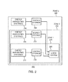
FIG. 2 is a block diagram of an alternative embodiment of the a self-contained electronic stowage bin system according to the present disclosure; -
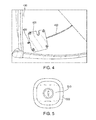
FIG. 3 is a diagram of a latch button according to an aspect of the present disclosure; -
FIG. 4 is a diagram of a latching mechanism according to an aspect of the present disclosure; and -
FIG. 5 is a diagram of an alternative embodiment of a latch button incorporating a bi-stable display for indicating latch status according to a further aspect of the present disclosure. - In the present disclosure, like reference numbers refer to like elements throughout the drawings, which illustrate various exemplary embodiments of the present disclosure.
- Referring now to
FIG. 1 , the latching system 100 (also referred to as a "self contained electronic latching system" or an "electronic latching system") of the present disclosure includes a latch button 110 (which may also incorporate a status indicator as discussed with respect toFIG. 5 below), anelectronic latching mechanism 120, anenergy storage device 130, one or moreenergy harvesting systems 140 and, optionally, lighting and/orcommunications devices 150. The latch button 110 is an electronic switch mounted, for example, on a door of an aircraft stowage bin that is used to activate thelatch mechanism 120. Thelatch mechanism 120 is shown in detail inFIG. 4 below and consists of, for example, one or more solenoid-driven devices which are used to push open the door of the aircraft stowage bin when activated and which also may incorporate elements used to secure or latch the door when a passenger or airline attendant pushes the door closed.Energy storage device 130 is any conventional device used for the storage of energy, including but not limited to a battery or capacitor and appropriate related electronic circuits. The energy harvesting system (or systems) 140 generate electricity by various methods as discussed below. Finally, lighting and/orcommunications devices 150 may also be locally powered viaenergy storage device 130 and may constitute architectural lighting for the local area, indicator lighting as discussed with respect toFIG. 5 , and system communications devices (e.g., powered speakers). - Devices used to capture energy may be vibration, piezoelectric, electromechanical (microgenerator), photovoltaic, thermoelectric, or some combination thereof, depending on the type of energy source identified for use. Examples of energy sources include, but are not limited to one or more of the following: (1) rotation of internal latch components; (2) additional linear motion capture of the latch strike interface; (3) rotation at pivot points (e.g., door hinges); (4) linear dampers; (5) motion capture; (6) cabin or external light; (7) thermal gradients; and (8) cabin vibration. In a further embodiment, particularly for new installations, the
energy harvesting system 140 may also include a direct connection to the aircraft power system that can provide power to supplement the power generated by the energy capture devices. - In one embodiment,
energy storage device 130 may be a rechargeable battery, so that the energy locally generated byenergy harvesting systems 140 may be used to continually maintain the energy storage level within such battery. In a further embodiment, the rechargeable battery is replaceable. In another embodiment,energy storage device 130 may be a capacitor (and associated electronic circuitry) that is charged by the energy locally generated byenergy harvesting systems 140. In some embodiments, a number of different energy sources are combined to compriseenergy harvesting systems 140, as necessary to maintain the required energy level inenergy storage device 130 that is necessary to operatelatch mechanism 120 and any optionally added ancillary equipment such as lighting/communications devices 150. - In the embodiment shown in
FIG. 1 , all of the component elements are self-contained and do not require direct connection to the aircraft power. This allows for easy retrofit of existing mechanically latched stowage bins in aircrafts. However, in other embodiments, it may be desirable to add energy harvesting systems which are not proximate to the particular aircraft stowage bin. - Referring now to
FIG. 2 , a latching system 200 (also referred to as an "electronic latching system") is shown which combines both local and remoteenergy harvesting systems system 200 includes a latch system 205 (consisting of, for example, latch button 110 andlatch mechanism 120 ofFIG. 1 ) coupled to a firstenergy storage device 210 and a first energy harvesting system (or systems) 215.Latch system 205, firstenergy storage device 210 and first energy harvesting system (or systems) 215 are located within a first zone 240 (Zone 1) that may be within the confines of the latching system of the aircraft stowage bin.System 200 also include a secondenergy storage device 220 and an associated secondenergy harvesting system 225 that is located within a second zone 250 (Zone 2), with secondenergy storage device 220 also coupled to supply power to latchsystem 205.Zone 2 250 may consist of the area within the confines of the aircraft stowage bin but separate from thelatch system 205. Finally,system 200 may also include a thirdenergy storage device 230 and an associated secondenergy harvesting system 235 that is located within a third zone 260 (Zone 3), with thirdenergy storage device 230 also coupled to supply power to latchsystem 205.Zone 3 350 may consist of the area external to the aircraft stowage bin within the aircraft. -
FIG. 3 shows alatch button system 300 mounted in adoor 305 of an aircraft stowage bin, including the activation orlatch button 310 within thelatch button system 300 that includes an electrical switch coupled to the latching mechanism (not shown inFIG. 3 ).FIG. 4 shows latching mechanism 400 mounted on asidewall 410 of an open aircraft stowage bin. As discussed above, latchingmechanism 400 includes a solenoid-drivenmember 420 that pushes the door of the aircraft stowage bin open upon activation and may also include latching elements used to keep the door closed when a passenger or airline attendant pushes the door closed. Acable 430 is coupled between the electronic switch inlatch button system 300 andlatching mechanism 400. When the latch button is activated by a passenger or airline attendant, an electrical signal is passed via electrical conductors incable 430 from the latch button to latchingmechanism 400 to causelatching mechanism 400 to push the door of the aircraft stowage bin open. - Referring now to
FIG. 5 , an alternative version of the latch button system is shown which incorporates, for example, a conventional low-energy bi-stable display on thesurface 510 oflatch button 500. This display may be used to indicate when the door of the aircraft stowage bin is not properly secured. The use of a bi-stable display minimizes energy drain, since such a display only requires energy to change states and does not continually consume energy. InFIG. 5 , the bi-stable display covers thecomplete surface 510 oflatch button 500, but in other embodiments, such display may cover only a portion thereof. In addition, the use of the character "!" is merely exemplary and, as one of ordinary skill in the art will readily recognize, any desired character or symbol may be used, and, in some cases, the symbol or character may be omitted and the color only may be relied upon to provide an indication that the door of the aircraft stowage bin is not properly secured (i.e., when the color is activated, the door is not closed). - By using a self-contained power generating source, the system disclosed herein combines the best features of mechanical latches (i.e., an independent design) and of electronic latches (i.e., lighter weight and feedback displays). The independent nature of this system allows use in both new aircraft (during construction) and existing aircraft (via retrofit of existing mechanical latch systems).
- Further, the disclosure comprises embodiments according to the following clauses:
-
Clause 1. A self-contained electronic latching system for a stowage bin, comprising: an energy storage device; an electronic latch device for opening a door of the stowage bin, the electronic latch device configured to open the door upon receipt of a signal on an input, the electronic latch device coupled to the energy storage device and configured to receive electrical power only from the energy storage device; a latch button for activating an electronic switch coupled to the input of the electronic latch device; and one or more energy harvesting systems coupled to the energy storage device, each of the one or more energy harvesting systems configured to generate electricity and to provide the generated electricity to the energy storage device. -
Clause 2. The self-contained electronic latching system ofClause 1, wherein the electronic latch device further comprises an element for securing the door in a closed position. -
Clause 3. The self-contained electronic latching system ofClause - Clause 4. The self-contained electronic latching system of
Clause - Clause 5. The self-contained electronic latching system of
Clause - Clause 6. The self-contained electronic latching system of
Clause - Clause 7. The self-contained electronic latching system of
Clause - Clause 8. The self-contained electronic latching system of
Clause - Clause 9. The self-contained electronic latching system of Clauses 1-8, wherein the energy storage devices is either a capacitor or a battery.
- Clause 10. The self-contained electronic latching system of Clauses 1-9, further comprising a low-energy bi-stable display mounted on a surface of the latch button, the low-energy bi-stable display providing an indication of a latching status of the door.
- Clause 11. An electronic latching system for a stowage bin, comprising: a first energy storage device; an electronic latch device for opening a door of the stowage bin, the electronic latch device configured to open the door upon receipt of a signal on an input, the electronic latch device coupled to the first energy storage device and configured to receive electrical power from the first energy storage device; a latch button for activating an electronic switch coupled to the input of the electronic latch device; and one or more first energy harvesting systems coupled to the first energy storage device, each of the one or more first energy harvesting systems configured to generate electricity and to provide the generated electricity to the first energy storage device, each of the one or more first energy harvesting systems incorporated into the latch button and configured to generate electricity based upon piezoelectric and/or electromechanical action.
- Clause 12. The electronic latching system of Clause 11, further comprising: a second energy storage device; one or more second energy harvesting systems coupled to the second energy storage device, each of the one or more second energy harvesting systems configured to generate electricity and to provide the generated electricity to the second energy storage device, each of the one or more second energy harvesting systems incorporated into the stowage bin; and wherein the electronic latch device is also coupled to the second energy storage device and is also configured to receive electrical power from the second energy storage device.
- Clause 13. The electronic latching system of Clause 12, wherein one of the one or more second energy harvesting systems is configured to generate electricity using a piezoelectric device and/or an electromechanical device.
- Clause 14. The electronic latching system of Clause 12 or 13, further comprising: a third energy storage device; one or more third energy harvesting systems coupled to the third energy storage device, each of the one or more third energy harvesting systems configured to generate electricity and to provide the generated electricity to the third energy storage device, each of the one or more third energy harvesting systems mounted outside of the stowage bin; and wherein the electronic latch device is also coupled to the third energy storage device and is also configured to receive electrical power from the third energy storage device.
- Clause 15. The electronic latching system of Clause 14, wherein one of the one or more third energy harvesting systems is configured to generate electricity using piezoelectric device and/or electromechanical device.
- Clause 16. The electronic latching system of Clause 14, wherein one of the one or more third energy harvesting systems is configured to generate electricity using a photovoltaic device.
- Clause 17. The electronic latching system of Clause 14, wherein one of the one or more third energy harvesting systems is configured to generate electricity using a thermoelectric device.
- Clause 18. The electronic latching system of Clause 14, wherein the stowage bin is mounted within an aircraft and wherein one of the one or more third energy harvesting systems is configured to generate electricity by harvesting aircraft cabin vibrations.
- Clause 19. The electronic latching system of Clause 11-18, further comprising a low-energy bi-stable display mounted on a surface of the latch button, the low-energy bi-stable display providing an indication of the latching status of the door.
- Clause 20. A method of operating a self-contained electronic latching system for a stowage bin, comprising the steps of: generating electricity in one or more energy harvesting systems; providing the generated electricity to an energy storage device; upon activation of a latch button, generating a signal in an electronic switch that is coupled to an input of an electronic latch device; and upon receipt of the signal at the input of the electronic latch device, causing a door of the stowage bin to open by activating the electronic latch device, the electronic latch device configured to receive electrical power only from the energy storage device.
- Although the present disclosure has been particularly shown and described with reference to the preferred embodiments and various aspects thereof, it will be appreciated by those of ordinary skill in the art that various changes and modifications may be made without departing from the spirit and scope of the disclosure. It is intended that the appended claims be interpreted as including the embodiments described herein, the alternatives mentioned above, and all equivalents thereto.
Claims (15)
- An electronic latching system (100, 200) for a stowage bin, comprising:an energy storage device (130);an electronic latching mechanism (120) for opening a door (305) of the stowage bin, the electronic latching mechanism configured to open the door upon receipt of a signal on an input, the electronic latching mechanism coupled to the energy storage device and configured to receive electrical power from the energy storage device;a latch button (110) including an electronic switch coupled to the input of the electronic latching mechanism; andone or more energy harvesting systems (140) coupled to the energy storage device, each of the one or more energy harvesting systems configured to generate electricity and to provide the generated electricity to the energy storage device.
- The electronic latching system (100) of claim 1, wherein the electronic latching mechanism (120) further comprises an element for securing the door (305) in a closed position.
- The electronic latching system (100) of claim 1 or 2, wherein one of the one or more energy harvesting systems (140) generates electricity one of based upon cabin vibrations, based upon motion supplied to a piezoelectric device, based upon motion supplied to an electromechanical device, using a photovoltaic device, and using a thermoelectric device.
- The electronic latching system (100) of claim 1 or 2, wherein one of the one or more energy harvesting systems (140) is incorporated into the latch button (110) and generates electricity using a piezoelectric device and/or an electromechanical device.
- The electronic latching system (100) of any one of claims 1 to 4, wherein the energy storage device (130) is either a capacitor or a battery.
- The electronic latching system (100) of any one of claims 1 to 5, further comprising a low-energy bi-stable display mounted on a surface (510) of the latch button (500), the low-energy bi-stable display providing an indication of a latching status of the door (305).
- The electronic latching system (200) of claim 1, wherein:the energy storage device (130) is a first energy storage device (210), wherein the electronic latching mechanism (120) is coupled to the first energy storage device and configured to receive electrical power from the first energy storage device;a latch system (205) comprises the latch button (110); andthe one or more energy harvesting systems (140) is one or more first energy harvesting systems (215) coupled to the first energy storage device, each of the one or more first energy harvesting systems incorporated into the latch button and configured to generate electricity based upon piezoelectric and/or electromechanical action, the electronic latching system further comprising:a second energy storage device (220);one or more second energy harvesting systems (225) coupled to the second energy storage device, each of the one or more second energy harvesting systems configured to generate electricity and to provide the generated electricity to the second energy storage device, each of the one or more second energy harvesting systems incorporated into the stowage bin; andwherein the latch system is also coupled to the second energy storage device and is also configured to receive electrical power from the second energy storage device.
- The electronic latching system (200) of claim 7, wherein one of the one or more second energy harvesting systems (225) is configured to generate electricity using a piezoelectric device and/or an electromechanical device.
- The electronic latching system (200) of claim 7 or 8, further comprising:a third energy storage device (230);one or more third energy harvesting systems (235) coupled to the third energy storage device, each of the one or more third energy harvesting systems configured to generate electricity and to provide the generated electricity to the third energy storage device, each of the one or more third energy harvesting systems mounted outside of the stowage bin; andwherein the latch system (205) is also coupled to the third energy storage device and is also configured to receive electrical power from the third energy storage device.
- The electronic latching system (200) of claim 9, wherein one of the one or more third energy harvesting systems (235) is configured to generate electricity using a piezoelectric device and/or an electromechanical device.
- The electronic latching system (200) of claim 9, wherein one of the one or more third energy harvesting systems (235) is configured to generate electricity using a photovoltaic device.
- The electronic latching system (200) of claim 9, wherein one of the one or more third energy harvesting systems (235) is configured to generate electricity using a thermoelectric device.
- The electronic latching system (200) of claim 9, wherein the stowage bin is mounted within an aircraft and wherein one of the one or more third energy harvesting systems (235) is configured to generate electricity by harvesting aircraft cabin vibrations.
- The electronic latching system (200) of claim 11, further comprising a low-energy bi-stable display mounted on a surface (510) of the latch button (110), the low-energy bi-stable display providing an indication of a latching status of the door (305).
- A method of operating a latching system (100) for a stowage bin, comprising the steps of:generating electricity in one or more energy harvesting systems (140);providing the generated electricity to an energy storage device (130);upon activation of a latch button (110), generating a signal in an electronic switch that is coupled to an input of an electronic latching mechanism (120); andupon receipt of the signal at the input of the electronic latching mechanism, causing a door (305) of the stowage bin to open by activating the electronic latching mechanism, the electronic latching mechanism configured to receive electrical power only from the energy storage device.
Applications Claiming Priority (1)
| Application Number | Priority Date | Filing Date | Title |
|---|---|---|---|
| US14/542,265 US20160138301A1 (en) | 2014-11-14 | 2014-11-14 | Self-contained electronic stowage bin system |
Publications (2)
| Publication Number | Publication Date |
|---|---|
| EP3020635A1 true EP3020635A1 (en) | 2016-05-18 |
| EP3020635B1 EP3020635B1 (en) | 2022-05-11 |
Family
ID=54359934
Family Applications (1)
| Application Number | Title | Priority Date | Filing Date |
|---|---|---|---|
| EP15190674.0A Active EP3020635B1 (en) | 2014-11-14 | 2015-10-20 | Self-contained electronic stowage bin system |
Country Status (4)
| Country | Link |
|---|---|
| US (1) | US20160138301A1 (en) |
| EP (1) | EP3020635B1 (en) |
| CN (1) | CN105599903A (en) |
| AU (1) | AU2015249036B2 (en) |
Families Citing this family (13)
| Publication number | Priority date | Publication date | Assignee | Title |
|---|---|---|---|---|
| WO2015148788A1 (en) * | 2014-03-26 | 2015-10-01 | Adac Plastics, Inc. | Handle assembly for a motor vehicle door |
| US9624693B2 (en) * | 2015-03-03 | 2017-04-18 | The Boeing Company | Integrated locks with visual indicators for aircraft galley systems |
| US10936879B2 (en) * | 2016-12-19 | 2021-03-02 | The Boeing Company | System for displaying the status of use of aircraft overhead luggage storage bins |
| US10906458B2 (en) | 2017-03-10 | 2021-02-02 | The Boeing Company | Vehicles including electronic stowage bin control systems |
| US10793277B2 (en) * | 2017-03-10 | 2020-10-06 | The Boeing Company | Electronic stowage bin control systems and methods |
| US10647429B2 (en) * | 2017-03-10 | 2020-05-12 | The Boeing Company | Vehicle stowage bin assemblies having weight sensors |
| US10864849B2 (en) | 2017-03-10 | 2020-12-15 | The Boeing Company | Illuminated stowage bin assemblies within vehicles |
| US10672208B2 (en) | 2017-03-10 | 2020-06-02 | The Boeing Company | Touch-free operable stowage bin assemblies |
| CN108729754A (en) * | 2017-04-19 | 2018-11-02 | 安钥(北京)科技股份有限公司 | A kind of power supply system and electronic lock of electronic lock |
| CN107769610B (en) * | 2017-10-20 | 2020-02-18 | 上海工程技术大学 | A luggage rack power generation device |
| CN113338722B (en) * | 2021-06-25 | 2022-06-21 | 西安理工大学 | An adjustable aircraft luggage compartment lock |
| US11970271B2 (en) | 2022-03-29 | 2024-04-30 | B/E Aerospace, Inc. | Energy harvesting recline button for aircraft seating |
| FR3162403A1 (en) * | 2024-05-22 | 2025-11-28 | Safran Seats | AIRCRAFT SEAT PRESENCE DETECTOR |
Citations (3)
| Publication number | Priority date | Publication date | Assignee | Title |
|---|---|---|---|---|
| US20080078871A1 (en) * | 2006-08-25 | 2008-04-03 | The Boeing Company | System and method for electronically latching compartments |
| US20090243842A1 (en) * | 2008-03-31 | 2009-10-01 | Mitchell Bradley J | Methods and systems for sensing activity using energy harvesting devices |
| EP2486958A1 (en) * | 2011-02-10 | 2012-08-15 | Intertechnique | Passenger cabin emergency oxygen device |
Family Cites Families (47)
| Publication number | Priority date | Publication date | Assignee | Title |
|---|---|---|---|---|
| US2272909A (en) * | 1940-10-17 | 1942-02-10 | Elmer A Fantl | Signal knob |
| US3398484A (en) * | 1965-06-04 | 1968-08-27 | Katsumura Toru | Car door actuator |
| US4348835A (en) * | 1979-12-31 | 1982-09-14 | Stanley Jones | Automatic door opening device |
| US4644693A (en) * | 1985-08-20 | 1987-02-24 | Wang Hong J | Electric device for opening or shutting automative doors |
| US4912460A (en) * | 1987-07-16 | 1990-03-27 | John Chu | Electrostatically activated gating mechanism |
| US5061923A (en) * | 1988-09-29 | 1991-10-29 | C & M Technology, Inc. | Computerized combination lock |
| JPH06229155A (en) * | 1992-01-13 | 1994-08-16 | C & M Technology Inc | Security lock mechanism |
| US5300875A (en) * | 1992-06-08 | 1994-04-05 | Micron Technology, Inc. | Passive (non-contact) recharging of secondary battery cell(s) powering RFID transponder tags |
| DE4228234A1 (en) * | 1992-08-25 | 1994-03-03 | Bayerische Motoren Werke Ag | Door lock for motor vehicles |
| US5694812A (en) * | 1995-04-28 | 1997-12-09 | United Technologies Automotive, Inc. | Multi-functional apparatus employing an electromagnetic device and an intermittent motion mechanism |
| EP0808977B1 (en) * | 1996-05-21 | 2000-08-16 | Robert Bosch Gmbh | Method for controlling an electrically actuated vehicle door lock |
| DE19724085C1 (en) * | 1997-06-07 | 1998-10-29 | Kiekert Ag | Vehicle door lock with external door handle and key reception |
| JP3060139U (en) * | 1998-11-13 | 1999-07-30 | 株式会社ジャムコ | Door latch device |
| US6589268B1 (en) * | 1998-12-10 | 2003-07-08 | Mcewen James A. | Hazard monitor for surgical tourniquet systems |
| US6236118B1 (en) * | 1999-11-24 | 2001-05-22 | Luciano Vasija | Method of generating electricity |
| JP2003133971A (en) * | 2001-10-29 | 2003-05-09 | Jigyo Sozo Kenkyusho:Kk | Self-powered transmitter |
| JP3975740B2 (en) * | 2001-12-14 | 2007-09-12 | アイシン精機株式会社 | Vehicle door control device |
| US6711856B1 (en) * | 2002-09-19 | 2004-03-30 | Drew Hoffman | Door opener assist device |
| JP2004108035A (en) * | 2002-09-19 | 2004-04-08 | Tokai Rika Co Ltd | Door opening and closing device |
| US7265684B2 (en) * | 2003-09-19 | 2007-09-04 | Saf-T-Glo Limited | Onboard equipment for aircraft and the like |
| GB0323268D0 (en) * | 2003-10-04 | 2003-11-05 | Arvinmeritor Light Vehicle Sys | Lock mechanism |
| US7791218B2 (en) * | 2003-11-13 | 2010-09-07 | Intier Automotive Closures Inc. | E-latch with microcontroller onboard latch and integrated backup sensor |
| JP4240307B2 (en) * | 2004-06-22 | 2009-03-18 | アイシン精機株式会社 | Vehicle door opening and closing device |
| US7597286B2 (en) * | 2005-09-12 | 2009-10-06 | Boeing Company | Simplified power system for a cabin services system for an aircraft |
| WO2007034474A1 (en) * | 2005-09-19 | 2007-03-29 | Meteoronics Ltd | Electric locks with release hammer |
| US7699365B2 (en) * | 2005-10-19 | 2010-04-20 | Vision Industries Group, Inc. | Sash lock with condition signal |
| US8456305B2 (en) * | 2005-11-22 | 2013-06-04 | Tell A. Gates | Redundant security system |
| US7552954B2 (en) * | 2006-02-13 | 2009-06-30 | The Boeing Company | Storage bin latch assembly |
| US7887008B2 (en) * | 2006-08-25 | 2011-02-15 | The Boeing Company | System and method for a power-assisted compartment |
| US7839124B2 (en) * | 2006-09-29 | 2010-11-23 | Semiconductor Energy Laboratory Co., Ltd. | Wireless power storage device comprising battery, semiconductor device including battery, and method for operating the wireless power storage device |
| KR101588579B1 (en) * | 2006-12-27 | 2016-01-26 | 가부시키가이샤 한도오따이 에네루기 켄큐쇼 | Switch device and power control system |
| US7823993B2 (en) * | 2007-04-03 | 2010-11-02 | Carefusion 303, Inc. | Piezo actuated slide latching mechanism |
| US7834483B2 (en) * | 2007-10-01 | 2010-11-16 | The Boeing Company | Energy harvesting system and method using multiple energy sources |
| US8022843B2 (en) * | 2008-03-31 | 2011-09-20 | The Boeing Company | Wireless aircraft sensor network |
| US7795746B2 (en) * | 2008-05-01 | 2010-09-14 | Robert Bosch Gmbh | Apparatus and method for generating power for a low current device |
| US20090282879A1 (en) * | 2008-05-15 | 2009-11-19 | Master Lock Company Llc | Lock assembly with rotary locking member |
| US8376416B2 (en) * | 2008-09-04 | 2013-02-19 | GM Global Technology Operations LLC | Latch system for a door of an automobile |
| US8528950B2 (en) * | 2010-02-01 | 2013-09-10 | Strattec Security Corporation | Latch mechanism and latching method |
| CA2737673C (en) * | 2010-04-15 | 2019-06-25 | Hanchett Entry Systems, Inc. | Electric door release powered by an energy harvester |
| US20120008336A1 (en) * | 2010-07-06 | 2012-01-12 | Otward Mueller | Aircraft Lighting System |
| US9431927B2 (en) * | 2012-05-07 | 2016-08-30 | Xceedid Corporation | System for harvesting energy from door or door hardware movement |
| CN102795332A (en) * | 2012-08-30 | 2012-11-28 | 湖南航天机电设备与特种材料研究所 | Wind and light complementary power generation tethered balloon |
| EP2945523B1 (en) * | 2013-01-17 | 2016-11-02 | Illinois Tool Works Inc. | Appliance lock with voltage encoded wiring |
| US9528298B2 (en) * | 2013-07-17 | 2016-12-27 | Illinois Tool Works, Inc. | Appliance latch with uni-directional actuator |
| US9416565B2 (en) * | 2013-11-21 | 2016-08-16 | Ford Global Technologies, Llc | Piezo based energy harvesting for e-latch systems |
| US9546502B2 (en) * | 2013-12-19 | 2017-01-17 | GM Global Technology Operations LLC | Door lock switch with lock state indicator |
| US20160130843A1 (en) * | 2014-11-12 | 2016-05-12 | Adac Plastics, Inc. | Low voltage backup assembly for electronic latch |
-
2014
- 2014-11-14 US US14/542,265 patent/US20160138301A1/en not_active Abandoned
-
2015
- 2015-10-20 EP EP15190674.0A patent/EP3020635B1/en active Active
- 2015-10-27 AU AU2015249036A patent/AU2015249036B2/en active Active
- 2015-11-11 CN CN201510771814.XA patent/CN105599903A/en active Pending
Patent Citations (3)
| Publication number | Priority date | Publication date | Assignee | Title |
|---|---|---|---|---|
| US20080078871A1 (en) * | 2006-08-25 | 2008-04-03 | The Boeing Company | System and method for electronically latching compartments |
| US20090243842A1 (en) * | 2008-03-31 | 2009-10-01 | Mitchell Bradley J | Methods and systems for sensing activity using energy harvesting devices |
| EP2486958A1 (en) * | 2011-02-10 | 2012-08-15 | Intertechnique | Passenger cabin emergency oxygen device |
Also Published As
| Publication number | Publication date |
|---|---|
| CN105599903A (en) | 2016-05-25 |
| EP3020635B1 (en) | 2022-05-11 |
| AU2015249036A1 (en) | 2016-06-02 |
| AU2015249036B2 (en) | 2020-05-28 |
| US20160138301A1 (en) | 2016-05-19 |
Similar Documents
| Publication | Publication Date | Title |
|---|---|---|
| EP3020635A1 (en) | Self-contained electronic stowage bin system | |
| US8665119B2 (en) | Electrically activated latch for aircraft stowage bins | |
| ES2652128T3 (en) | Electronic lock for cabinet doors, drawers and other applications | |
| US9589461B1 (en) | Battery powered wall mounted remote control for ceiling fans and lights | |
| US20170040827A1 (en) | Closure member wireless power system for a closable opening | |
| US8882033B2 (en) | Passenger cabin emergency oxygen device | |
| US20130127180A1 (en) | Motor vehicle door | |
| WO2009023413A3 (en) | Electric current conduction system for appliance | |
| US20200347642A1 (en) | Lock with key storage room | |
| CN107215469A (en) | The adjustable locking of airborne vehicle compartment baffle plate | |
| US9637235B2 (en) | Method for monitoring and locking aircraft compartment doors | |
| CN102632995B (en) | The method of aircraft, passenger accommodation emergency oxygen equipment and operation and this equipment of activation | |
| US10518745B2 (en) | Locking device | |
| KR20180113310A (en) | Electric door lock charging equipment using how to induce electromagnetic wave and the method of the same | |
| US10711500B1 (en) | Permanent magnet damping and generated light | |
| GB2532311A (en) | Power control circuit assembly for an electric door latch mechanism | |
| CN202559877U (en) | Box cover locking device, controllable storage box comprising the device, and medicine and consumable access system | |
| CN211046520U (en) | Wireless charging equipment and electronic lock device | |
| NO341487B1 (en) | Procedure for mounting a key box, as well as a key box for locked storage of encoded access objects | |
| US20210175960A1 (en) | Exit sign with access control | |
| EP3734000A1 (en) | Electric lock device, electronic lock system, access member and access member system | |
| RU2609400C1 (en) | Door hinge | |
| JP2016191287A (en) | Door lighting device | |
| CN107358757A (en) | Express delivery cabinet with drawer-type storage bin | |
| KR20140146460A (en) | Ordinary power supply for digital door locking system |
Legal Events
| Date | Code | Title | Description |
|---|---|---|---|
| PUAI | Public reference made under article 153(3) epc to a published international application that has entered the european phase |
Free format text: ORIGINAL CODE: 0009012 |
|
| 17P | Request for examination filed |
Effective date: 20151020 |
|
| AK | Designated contracting states |
Kind code of ref document: A1 Designated state(s): AL AT BE BG CH CY CZ DE DK EE ES FI FR GB GR HR HU IE IS IT LI LT LU LV MC MK MT NL NO PL PT RO RS SE SI SK SM TR |
|
| AX | Request for extension of the european patent |
Extension state: BA ME |
|
| RBV | Designated contracting states (corrected) |
Designated state(s): AL AT BE BG CH CY CZ DE DK EE ES FI FR GB GR HR HU IE IS IT LI LT LU LV MC MK MT NL NO PL PT RO RS SE SI SK SM TR |
|
| STAA | Information on the status of an ep patent application or granted ep patent |
Free format text: STATUS: EXAMINATION IS IN PROGRESS |
|
| 17Q | First examination report despatched |
Effective date: 20190510 |
|
| GRAP | Despatch of communication of intention to grant a patent |
Free format text: ORIGINAL CODE: EPIDOSNIGR1 |
|
| STAA | Information on the status of an ep patent application or granted ep patent |
Free format text: STATUS: GRANT OF PATENT IS INTENDED |
|
| INTG | Intention to grant announced |
Effective date: 20210820 |
|
| GRAJ | Information related to disapproval of communication of intention to grant by the applicant or resumption of examination proceedings by the epo deleted |
Free format text: ORIGINAL CODE: EPIDOSDIGR1 |
|
| STAA | Information on the status of an ep patent application or granted ep patent |
Free format text: STATUS: EXAMINATION IS IN PROGRESS |
|
| GRAP | Despatch of communication of intention to grant a patent |
Free format text: ORIGINAL CODE: EPIDOSNIGR1 |
|
| STAA | Information on the status of an ep patent application or granted ep patent |
Free format text: STATUS: GRANT OF PATENT IS INTENDED |
|
| INTC | Intention to grant announced (deleted) | ||
| INTG | Intention to grant announced |
Effective date: 20211222 |
|
| GRAS | Grant fee paid |
Free format text: ORIGINAL CODE: EPIDOSNIGR3 |
|
| GRAA | (expected) grant |
Free format text: ORIGINAL CODE: 0009210 |
|
| STAA | Information on the status of an ep patent application or granted ep patent |
Free format text: STATUS: THE PATENT HAS BEEN GRANTED |
|
| AK | Designated contracting states |
Kind code of ref document: B1 Designated state(s): AL AT BE BG CH CY CZ DE DK EE ES FI FR GB GR HR HU IE IS IT LI LT LU LV MC MK MT NL NO PL PT RO RS SE SI SK SM TR |
|
| REG | Reference to a national code |
Ref country code: GB Ref legal event code: FG4D |
|
| REG | Reference to a national code |
Ref country code: CH Ref legal event code: EP |
|
| REG | Reference to a national code |
Ref country code: AT Ref legal event code: REF Ref document number: 1491228 Country of ref document: AT Kind code of ref document: T Effective date: 20220515 |
|
| REG | Reference to a national code |
Ref country code: DE Ref legal event code: R096 Ref document number: 602015078858 Country of ref document: DE |
|
| REG | Reference to a national code |
Ref country code: IE Ref legal event code: FG4D |
|
| REG | Reference to a national code |
Ref country code: LT Ref legal event code: MG9D |
|
| REG | Reference to a national code |
Ref country code: NL Ref legal event code: MP Effective date: 20220511 |
|
| REG | Reference to a national code |
Ref country code: AT Ref legal event code: MK05 Ref document number: 1491228 Country of ref document: AT Kind code of ref document: T Effective date: 20220511 |
|
| PG25 | Lapsed in a contracting state [announced via postgrant information from national office to epo] |
Ref country code: SE Free format text: LAPSE BECAUSE OF FAILURE TO SUBMIT A TRANSLATION OF THE DESCRIPTION OR TO PAY THE FEE WITHIN THE PRESCRIBED TIME-LIMIT Effective date: 20220511 Ref country code: PT Free format text: LAPSE BECAUSE OF FAILURE TO SUBMIT A TRANSLATION OF THE DESCRIPTION OR TO PAY THE FEE WITHIN THE PRESCRIBED TIME-LIMIT Effective date: 20220912 Ref country code: NO Free format text: LAPSE BECAUSE OF FAILURE TO SUBMIT A TRANSLATION OF THE DESCRIPTION OR TO PAY THE FEE WITHIN THE PRESCRIBED TIME-LIMIT Effective date: 20220811 Ref country code: NL Free format text: LAPSE BECAUSE OF FAILURE TO SUBMIT A TRANSLATION OF THE DESCRIPTION OR TO PAY THE FEE WITHIN THE PRESCRIBED TIME-LIMIT Effective date: 20220511 Ref country code: LT Free format text: LAPSE BECAUSE OF FAILURE TO SUBMIT A TRANSLATION OF THE DESCRIPTION OR TO PAY THE FEE WITHIN THE PRESCRIBED TIME-LIMIT Effective date: 20220511 Ref country code: HR Free format text: LAPSE BECAUSE OF FAILURE TO SUBMIT A TRANSLATION OF THE DESCRIPTION OR TO PAY THE FEE WITHIN THE PRESCRIBED TIME-LIMIT Effective date: 20220511 Ref country code: GR Free format text: LAPSE BECAUSE OF FAILURE TO SUBMIT A TRANSLATION OF THE DESCRIPTION OR TO PAY THE FEE WITHIN THE PRESCRIBED TIME-LIMIT Effective date: 20220812 Ref country code: FI Free format text: LAPSE BECAUSE OF FAILURE TO SUBMIT A TRANSLATION OF THE DESCRIPTION OR TO PAY THE FEE WITHIN THE PRESCRIBED TIME-LIMIT Effective date: 20220511 Ref country code: ES Free format text: LAPSE BECAUSE OF FAILURE TO SUBMIT A TRANSLATION OF THE DESCRIPTION OR TO PAY THE FEE WITHIN THE PRESCRIBED TIME-LIMIT Effective date: 20220511 Ref country code: BG Free format text: LAPSE BECAUSE OF FAILURE TO SUBMIT A TRANSLATION OF THE DESCRIPTION OR TO PAY THE FEE WITHIN THE PRESCRIBED TIME-LIMIT Effective date: 20220811 Ref country code: AT Free format text: LAPSE BECAUSE OF FAILURE TO SUBMIT A TRANSLATION OF THE DESCRIPTION OR TO PAY THE FEE WITHIN THE PRESCRIBED TIME-LIMIT Effective date: 20220511 |
|
| PG25 | Lapsed in a contracting state [announced via postgrant information from national office to epo] |
Ref country code: RS Free format text: LAPSE BECAUSE OF FAILURE TO SUBMIT A TRANSLATION OF THE DESCRIPTION OR TO PAY THE FEE WITHIN THE PRESCRIBED TIME-LIMIT Effective date: 20220511 Ref country code: PL Free format text: LAPSE BECAUSE OF FAILURE TO SUBMIT A TRANSLATION OF THE DESCRIPTION OR TO PAY THE FEE WITHIN THE PRESCRIBED TIME-LIMIT Effective date: 20220511 Ref country code: LV Free format text: LAPSE BECAUSE OF FAILURE TO SUBMIT A TRANSLATION OF THE DESCRIPTION OR TO PAY THE FEE WITHIN THE PRESCRIBED TIME-LIMIT Effective date: 20220511 Ref country code: IS Free format text: LAPSE BECAUSE OF FAILURE TO SUBMIT A TRANSLATION OF THE DESCRIPTION OR TO PAY THE FEE WITHIN THE PRESCRIBED TIME-LIMIT Effective date: 20220911 |
|
| PG25 | Lapsed in a contracting state [announced via postgrant information from national office to epo] |
Ref country code: SM Free format text: LAPSE BECAUSE OF FAILURE TO SUBMIT A TRANSLATION OF THE DESCRIPTION OR TO PAY THE FEE WITHIN THE PRESCRIBED TIME-LIMIT Effective date: 20220511 Ref country code: SK Free format text: LAPSE BECAUSE OF FAILURE TO SUBMIT A TRANSLATION OF THE DESCRIPTION OR TO PAY THE FEE WITHIN THE PRESCRIBED TIME-LIMIT Effective date: 20220511 Ref country code: RO Free format text: LAPSE BECAUSE OF FAILURE TO SUBMIT A TRANSLATION OF THE DESCRIPTION OR TO PAY THE FEE WITHIN THE PRESCRIBED TIME-LIMIT Effective date: 20220511 Ref country code: EE Free format text: LAPSE BECAUSE OF FAILURE TO SUBMIT A TRANSLATION OF THE DESCRIPTION OR TO PAY THE FEE WITHIN THE PRESCRIBED TIME-LIMIT Effective date: 20220511 Ref country code: DK Free format text: LAPSE BECAUSE OF FAILURE TO SUBMIT A TRANSLATION OF THE DESCRIPTION OR TO PAY THE FEE WITHIN THE PRESCRIBED TIME-LIMIT Effective date: 20220511 Ref country code: CZ Free format text: LAPSE BECAUSE OF FAILURE TO SUBMIT A TRANSLATION OF THE DESCRIPTION OR TO PAY THE FEE WITHIN THE PRESCRIBED TIME-LIMIT Effective date: 20220511 |
|
| REG | Reference to a national code |
Ref country code: DE Ref legal event code: R097 Ref document number: 602015078858 Country of ref document: DE |
|
| PLBE | No opposition filed within time limit |
Free format text: ORIGINAL CODE: 0009261 |
|
| STAA | Information on the status of an ep patent application or granted ep patent |
Free format text: STATUS: NO OPPOSITION FILED WITHIN TIME LIMIT |
|
| RAP4 | Party data changed (patent owner data changed or rights of a patent transferred) |
Owner name: THE BOEING COMPANY |
|
| PG25 | Lapsed in a contracting state [announced via postgrant information from national office to epo] |
Ref country code: AL Free format text: LAPSE BECAUSE OF FAILURE TO SUBMIT A TRANSLATION OF THE DESCRIPTION OR TO PAY THE FEE WITHIN THE PRESCRIBED TIME-LIMIT Effective date: 20220511 |
|
| 26N | No opposition filed |
Effective date: 20230214 |
|
| PG25 | Lapsed in a contracting state [announced via postgrant information from national office to epo] |
Ref country code: SI Free format text: LAPSE BECAUSE OF FAILURE TO SUBMIT A TRANSLATION OF THE DESCRIPTION OR TO PAY THE FEE WITHIN THE PRESCRIBED TIME-LIMIT Effective date: 20220511 Ref country code: MC Free format text: LAPSE BECAUSE OF FAILURE TO SUBMIT A TRANSLATION OF THE DESCRIPTION OR TO PAY THE FEE WITHIN THE PRESCRIBED TIME-LIMIT Effective date: 20220511 |
|
| REG | Reference to a national code |
Ref country code: CH Ref legal event code: PL |
|
| P01 | Opt-out of the competence of the unified patent court (upc) registered |
Effective date: 20230516 |
|
| REG | Reference to a national code |
Ref country code: BE Ref legal event code: MM Effective date: 20221031 |
|
| PG25 | Lapsed in a contracting state [announced via postgrant information from national office to epo] |
Ref country code: LU Free format text: LAPSE BECAUSE OF NON-PAYMENT OF DUE FEES Effective date: 20221020 |
|
| PG25 | Lapsed in a contracting state [announced via postgrant information from national office to epo] |
Ref country code: LI Free format text: LAPSE BECAUSE OF NON-PAYMENT OF DUE FEES Effective date: 20221031 Ref country code: CH Free format text: LAPSE BECAUSE OF NON-PAYMENT OF DUE FEES Effective date: 20221031 |
|
| PG25 | Lapsed in a contracting state [announced via postgrant information from national office to epo] |
Ref country code: BE Free format text: LAPSE BECAUSE OF NON-PAYMENT OF DUE FEES Effective date: 20221031 |
|
| PG25 | Lapsed in a contracting state [announced via postgrant information from national office to epo] |
Ref country code: IE Free format text: LAPSE BECAUSE OF NON-PAYMENT OF DUE FEES Effective date: 20221020 |
|
| PG25 | Lapsed in a contracting state [announced via postgrant information from national office to epo] |
Ref country code: IT Free format text: LAPSE BECAUSE OF FAILURE TO SUBMIT A TRANSLATION OF THE DESCRIPTION OR TO PAY THE FEE WITHIN THE PRESCRIBED TIME-LIMIT Effective date: 20220511 |
|
| PG25 | Lapsed in a contracting state [announced via postgrant information from national office to epo] |
Ref country code: HU Free format text: LAPSE BECAUSE OF FAILURE TO SUBMIT A TRANSLATION OF THE DESCRIPTION OR TO PAY THE FEE WITHIN THE PRESCRIBED TIME-LIMIT; INVALID AB INITIO Effective date: 20151020 |
|
| PG25 | Lapsed in a contracting state [announced via postgrant information from national office to epo] |
Ref country code: CY Free format text: LAPSE BECAUSE OF FAILURE TO SUBMIT A TRANSLATION OF THE DESCRIPTION OR TO PAY THE FEE WITHIN THE PRESCRIBED TIME-LIMIT Effective date: 20220511 |
|
| PG25 | Lapsed in a contracting state [announced via postgrant information from national office to epo] |
Ref country code: MK Free format text: LAPSE BECAUSE OF FAILURE TO SUBMIT A TRANSLATION OF THE DESCRIPTION OR TO PAY THE FEE WITHIN THE PRESCRIBED TIME-LIMIT Effective date: 20220511 |
|
| PG25 | Lapsed in a contracting state [announced via postgrant information from national office to epo] |
Ref country code: MT Free format text: LAPSE BECAUSE OF FAILURE TO SUBMIT A TRANSLATION OF THE DESCRIPTION OR TO PAY THE FEE WITHIN THE PRESCRIBED TIME-LIMIT Effective date: 20220511 |
|
| PG25 | Lapsed in a contracting state [announced via postgrant information from national office to epo] |
Ref country code: BG Free format text: LAPSE BECAUSE OF FAILURE TO SUBMIT A TRANSLATION OF THE DESCRIPTION OR TO PAY THE FEE WITHIN THE PRESCRIBED TIME-LIMIT Effective date: 20220511 |
|
| PG25 | Lapsed in a contracting state [announced via postgrant information from national office to epo] |
Ref country code: BG Free format text: LAPSE BECAUSE OF FAILURE TO SUBMIT A TRANSLATION OF THE DESCRIPTION OR TO PAY THE FEE WITHIN THE PRESCRIBED TIME-LIMIT Effective date: 20220511 |
|
| PG25 | Lapsed in a contracting state [announced via postgrant information from national office to epo] |
Ref country code: TR Free format text: LAPSE BECAUSE OF FAILURE TO SUBMIT A TRANSLATION OF THE DESCRIPTION OR TO PAY THE FEE WITHIN THE PRESCRIBED TIME-LIMIT Effective date: 20220511 |
|
| PGFP | Annual fee paid to national office [announced via postgrant information from national office to epo] |
Ref country code: DE Payment date: 20251029 Year of fee payment: 11 |
|
| PGFP | Annual fee paid to national office [announced via postgrant information from national office to epo] |
Ref country code: GB Payment date: 20251027 Year of fee payment: 11 |
|
| PGFP | Annual fee paid to national office [announced via postgrant information from national office to epo] |
Ref country code: FR Payment date: 20251027 Year of fee payment: 11 |