EP3020440A1 - Phototherapy display device and method for controlling the same - Google Patents
Phototherapy display device and method for controlling the same Download PDFInfo
- Publication number
- EP3020440A1 EP3020440A1 EP15194245.5A EP15194245A EP3020440A1 EP 3020440 A1 EP3020440 A1 EP 3020440A1 EP 15194245 A EP15194245 A EP 15194245A EP 3020440 A1 EP3020440 A1 EP 3020440A1
- Authority
- EP
- European Patent Office
- Prior art keywords
- image
- sub
- image frame
- display device
- signal
- Prior art date
- Legal status (The legal status is an assumption and is not a legal conclusion. Google has not performed a legal analysis and makes no representation as to the accuracy of the status listed.)
- Granted
Links
Images


Classifications
-
- A—HUMAN NECESSITIES
- A61—MEDICAL OR VETERINARY SCIENCE; HYGIENE
- A61N—ELECTROTHERAPY; MAGNETOTHERAPY; RADIATION THERAPY; ULTRASOUND THERAPY
- A61N5/00—Radiation therapy
- A61N5/06—Radiation therapy using light
-
- A—HUMAN NECESSITIES
- A61—MEDICAL OR VETERINARY SCIENCE; HYGIENE
- A61M—DEVICES FOR INTRODUCING MEDIA INTO, OR ONTO, THE BODY; DEVICES FOR TRANSDUCING BODY MEDIA OR FOR TAKING MEDIA FROM THE BODY; DEVICES FOR PRODUCING OR ENDING SLEEP OR STUPOR
- A61M21/00—Other devices or methods to cause a change in the state of consciousness; Devices for producing or ending sleep by mechanical, optical, or acoustical means, e.g. for hypnosis
-
- G—PHYSICS
- G06—COMPUTING OR CALCULATING; COUNTING
- G06T—IMAGE DATA PROCESSING OR GENERATION, IN GENERAL
- G06T5/00—Image enhancement or restoration
- G06T5/70—Denoising; Smoothing
-
- A—HUMAN NECESSITIES
- A61—MEDICAL OR VETERINARY SCIENCE; HYGIENE
- A61M—DEVICES FOR INTRODUCING MEDIA INTO, OR ONTO, THE BODY; DEVICES FOR TRANSDUCING BODY MEDIA OR FOR TAKING MEDIA FROM THE BODY; DEVICES FOR PRODUCING OR ENDING SLEEP OR STUPOR
- A61M21/00—Other devices or methods to cause a change in the state of consciousness; Devices for producing or ending sleep by mechanical, optical, or acoustical means, e.g. for hypnosis
- A61M2021/0005—Other devices or methods to cause a change in the state of consciousness; Devices for producing or ending sleep by mechanical, optical, or acoustical means, e.g. for hypnosis by the use of a particular sense, or stimulus
- A61M2021/0044—Other devices or methods to cause a change in the state of consciousness; Devices for producing or ending sleep by mechanical, optical, or acoustical means, e.g. for hypnosis by the use of a particular sense, or stimulus by the sight sense
-
- A—HUMAN NECESSITIES
- A61—MEDICAL OR VETERINARY SCIENCE; HYGIENE
- A61M—DEVICES FOR INTRODUCING MEDIA INTO, OR ONTO, THE BODY; DEVICES FOR TRANSDUCING BODY MEDIA OR FOR TAKING MEDIA FROM THE BODY; DEVICES FOR PRODUCING OR ENDING SLEEP OR STUPOR
- A61M2205/00—General characteristics of the apparatus
- A61M2205/50—General characteristics of the apparatus with microprocessors or computers
- A61M2205/502—User interfaces, e.g. screens or keyboards
- A61M2205/505—Touch-screens; Virtual keyboard or keypads; Virtual buttons; Soft keys; Mouse touches
-
- A—HUMAN NECESSITIES
- A61—MEDICAL OR VETERINARY SCIENCE; HYGIENE
- A61N—ELECTROTHERAPY; MAGNETOTHERAPY; RADIATION THERAPY; ULTRASOUND THERAPY
- A61N5/00—Radiation therapy
- A61N5/06—Radiation therapy using light
- A61N2005/0626—Monitoring, verifying, controlling systems and methods
-
- G—PHYSICS
- G06—COMPUTING OR CALCULATING; COUNTING
- G06T—IMAGE DATA PROCESSING OR GENERATION, IN GENERAL
- G06T2207/00—Indexing scheme for image analysis or image enhancement
- G06T2207/20—Special algorithmic details
- G06T2207/20172—Image enhancement details
Definitions
- the present invention generally relates to flat panel display devices, and more specifically relates to a display device and associated control methods for facilitating treatment of a disease or disorder using light.
- Light exposure methods have been developed recently, for treatment of diseases or disorders. These treatment methods include a method of exposing a patient to light of a specific wavelength band, and a method of exposing a patient to light in combination with a drug therapy. Such treatment methods are typically referred to as a phototherapy.
- Phototherapy has been used, for example, for treatment of diseases such as jaundice of the newborn, acne, psoriasis, eczema, cancer, neurological disorders, seasonal affective disorder, depression, bulimia, hand tremor associated with Parkinson's disease, ulcers, and circadian rhythm maintenance disorders as well as other diseases, disorders, or illnesses.
- Phototherapy has been used to promote injury recovery, to promote relaxation, to improve fertility, to stimulate hair growth, and to reduce expression of cellulite and wrinkles.
- phototherapy devices have been developed for treatment of a specific disease. In general, these phototherapy devices are designed to transmit specifically controlled light to the patient.
- the phototherapy devices may use fluorescent lamps, halogen lamps, inorganic or organic light emitting diodes as a direct spot light, or in combination with optical fibers.
- the effectiveness of phototherapy is generally dependent on the intensity of light used, a surface area exposed to light, and a percentage of a light spectrum that includes an effective wavelength for treatment of diseases or disorders.
- Embodiments of the present invention seek to solve the aforementioned problems and other problems by providing a display device and a control method therefor, for enabling treatment of a specific disease or disorder by using light, and by providing a display device and a control method therefor for reducing distortion of a display image due to phototherapy.
- a display device may include: a display unit including a plurality of pixels; and a controller arranged to receive an image signal comprising a plurality of image frames. If the certain of the image frames are determined to represent a still image, the controller is arranged to insert a sub-image frame between immediately successive image frames of the certain of the image frames, the sub-image frame allowing at least one of the plurality of pixels to emit light of a specified wavelength.
- the controller may be further constructed to separate a first one of the image frames into a plurality of sub-images, compare the plurality of sub-images with corresponding sub-images of a previous one of the image frames that is received before the first image frame, detect whether the compared sub-images differ from each other, and thereby determine whether the image signal represents the still image signal.
- the display device may further include a memory storing information corresponding to the specified wavelength of light to be emitted.
- the controller may be further arranged to receive a control signal for controlling insertion of the sub-image frame, and may read the information from the memory according to the control signal.
- the plurality of image frames may include immediately successive first and second image frames, and the controller may be further constructed to insert the sub-image frame such that an interval between the first image frame and the sub-image frame is greater than that between the sub-image frame and the second image frame.
- the control signal may include a signal directing the controller to selectively read the information corresponding to the specified wavelength.
- the controller may be further constructed to correct a color of the image signal at least partially according to the specified wavelength of the sub-image frame that is selected by the control signal.
- the controller may be further constructed to correct the color of the image signal at least partially according to a ratio of the interval between the first image frame and the sub-image frame to the interval between the sub-image frame and the second image frame.
- the memory may further store information corresponding to a color correction matrix for correcting the color of the image signal.
- the controller may be further constructed to read the information, and to insert ones of the sub-image frames between successive image frames.
- the control signal may include a signal for directing the controller such that the sub-image frame for emitting light of a wavelength corresponding to a specific time zone is displayed.
- a method of controlling a display device includes: receiving an image signal; determining whether the image signal represents a still image; and inserting, if the image signal is determined to represent a still image, a sub-image frame between immediately successive image frames, the sub-image frame allowing at least one of the plurality of pixels to emit light of a specified wavelength.
- the determining may further include: separating a first one of the image frames into a plurality of sub-images; and detecting whether the sub-images of successive image frames represent a still image, by comparing the sub-images of the first one of the image frames with the corresponding sub-images of a previous image frame.
- the method may further include: receiving a control signal for controlling insertion of the sub-image frame; and reading, from a memory, information corresponding to a specified wavelength of light to be emitted according to the sub-image frame.
- the inserting may further include inserting the sub-image frame between successive first and second ones of the image frames so that an interval between the first image frame and the sub-image frame is greater than an interval between the sub-image frame and the second image frame.
- the reading may further include selectively reading the information from the memory.
- the method may further include correcting a color of the image signal according to the specified wavelength corresponding to the selectively read information.
- the correcting may further include correcting the color of the image signal at least partially according to a ratio of the interval between the first image frame and the sub-image frame to the interval between the sub-image frame and the second image frame.
- the information may correspond to multiple ones of the specified wavelengths.
- the inserting may further include respectively sequentially inserting multiple ones of the sub-image frames each between two immediately successive image frames.
- At least one of the exemplary embodiments may advantageously reduce distortion of displayed images and aid in treat specific diseases or disorders.
- module and “unit” for components used in the following description are used only in order to easily make a specification. Therefore, these terms do not have meanings or roles that distinguish them from each other in themselves.
- a display device described in the present specification may include digital TVs, mobile phones, smartphones, laptop computers, digital broadcasting terminals, personal digital assistants (PDAs), portable multimedia players (PMPs), navigation devices, slate PCs, tablet PCs, ultrabooks, wearable devices (e.g., watch-type terminals (smart watches), glasses type terminals (smart glasses), head mounted displays (HMDs), desktop computers, digital signages, etc.
- PDAs personal digital assistants
- PMPs portable multimedia players
- navigation devices slate PCs
- slate PCs slate PCs
- tablet PCs tablet PCs
- ultrabooks ultrabooks
- wearable devices e.g., watch-type terminals (smart watches), glasses type terminals (smart glasses), head mounted displays (HMDs), desktop computers, digital signages, etc.
- FIG. 1 is a block diagram of a display device related to an embodiment of the invention.
- the display device includes a display unit 130 including a plurality of pixels PX, a scan driver 120, a data driver 110, a timing controller 100, and a memory 140. Further, the display device may be connected to an application processor 200. In addition, a user input unit 210 may be connected to the application processor 200. The application processor 200 and the user input unit 210 may be provided outside of the display device, or may be incorporated in the display device.
- the constituent elements illustrated in FIG. 1 are not essential for embodiment of the display device, so the display device described in the present specification may include more or fewer constituent elements than those described above.
- the display unit 130 is a display panel including a plurality of pixels PX that are connected to corresponding scan lines S1 to Sn and corresponding data lines D1 to Dm.
- Each of the plurality of pixels PX displays an image in accordance with an image data signal that is transmitted to the corresponding pixels PX.
- the plurality of pixels PX included in the display unit 130 are respectively connected to the plurality of scan lines S1 to Sn and the plurality of data lines D1 to Dm, and are arranged in an approximate matrix form.
- the plurality of scan lines S1 to Sn substantially extends in a row direction such that, in the embodiment shown, they are almost parallel to each other.
- the data lines D1 to Dm substantially extend in a column direction such that, in this embodiment, they are almost parallel to each other.
- the scan driver 120 is connected to the display unit 130 via the plurality of scan lines S1 to Sn.
- the scan driver 120 generates a plurality of scan signals for activating each pixel PX of the display unit 130 according to a scan control signal CONT2, and transmits the scan signals to the corresponding scan lines S1 to Sn.
- the scan control signal CONT2 is a signal for controlling an operation of the scan driver 120, and is generated by the timing controller 100.
- the scan control signal CONT2 may include a scan start signal, a clock signal CLK (not shown but included in CONT2 in, for example, known manner), etc.
- the scan start signal is a signal for generating a first scan signal for displaying one frame of an image.
- the clock signal CLK is a synchronization signal for sequentially applying the scan signals to the plurality of scan lines S1 to Sn.
- the data driver 110 is connected to each pixel PX of the display unit 130 via the plurality of data lines D1 to Dm.
- the data driver 110 receives an image data signal DATA and transmits it to the corresponding data lines D1 to Dm according to a data control signal CONT1.
- the data control signal CONT1 is a signal for controlling an operation of the data driver 110, and is generated by the timing controller 100.
- the data driver 110 selects a gray voltage according to the image data signal DATA, and transmits it as a data signal to the appropriate one of the data lines D1 to Dm.
- the timing controller 100 may receive an image signal IS that is received from the application processor 200, an input control signal for controlling display of the image signal IS, and a phototherapy control signal CONTS.
- the image signal IS contains luminance information about each pixel PX of the display unit 130, and luminance has a predetermined number of grays, for example, 1024, 256, or 64.
- Examples of the input control signal transmitted to the timing controller 100 are a vertical synchronization signal, a horizontal synchronization signal, a main clock signal MCLK, a data enable signal, etc.
- the timing controller 100 may display a phototherapy image on the display unit 130 according to the phototherapy control signal CONTS.
- the timing controller 100 may transmit a signal READ for reading the phototherapy image to the memory 140 and may also read a phototherapy image signal T_IS from the memory 140.
- the timing controller 100 may receive the image signal per frame and detect whether the image signal is a still image or not. Further, depending on whether the image signal is a still image or not, the timing controller 100 may generate a signal for controlling the phototherapy image to be displayed in the display unit 130.
- the timing controller 100 separates a current frame image of a current input image into a plurality of sub-images. In addition, the timing controller 100 compares the plurality of sub-images with corresponding sub-images of a previous frame image that is previously received, and detects whether each of the sub-images is different from its corresponding previous frame or not.
- the timing controller 100 separates the frame image included in the input image signal into two sub-images, i.e., first and second sub-images, compares a pixel value of one of the sub-images with that of the corresponding sub-image of the previous frame image, and determines whether the sub-image as the still image, i.e. a motionless image, if a difference between the two pixel values is below a predetermined threshold value.
- the image is determined to be a moving image if the difference between the pixel values exceeds a predetermined threshold value.
- the timing controller 100 may read the phototherapy image signal T_IS from the memory 140, and mix it with the image signal to generate the image data signal DATA. Further, the timing controller 100 appropriately image-processes the image signal IS and/or the phototherapy image signal T_IS such that they meet an operating condition of (e.g., are in the proper format for) the display unit 130 and the data driver 110 based on the image signal IS, the phototherapy image signal T_IS, the input control signal, and the phototherapy control signal CONTS that are received.
- an operating condition of e.g., are in the proper format for
- the timing controller 100 may generate the image data signal DATA by performing various image-processing processes on the image signal IS, such as gamma correction, luminance compensation, color correction, etc.
- the timing controller 100 may generate the image data signal DATA such that the image according to the image signal IS and the image according to the phototherapy image signal T_IS are appropriately mixed and displayed. In addition, the timing controller 100 may correct a color of the image signal IS according to the phototherapy image signal T_IS. This will be described later with reference to FIG. 2 .
- the timing controller 100 transmits the scan control signal CONT2, for controlling the operation of the scan driver 120, to the scan driver 120.
- the timing controller 100 generates the data control signal CONT1 for controlling the operation of the data driver 110, and transmits the data control signal CONT1 along with the previously image-processed image data signal DATA to the data driver 110.
- the memory 140 stores color correction matrix values corresponding to a plurality of phototherapy image signals T_IS, and also stores each of the phototherapy images.
- the timing controller 100 may calculate the corresponding color correction matrix value with the image signal, to correct the color of the image signal.
- the color correction matrix values are different depending on wavelengths of the respective phototherapy images.
- a color mixture between the phototherapy image and the display image may occur. That is, affected by light of a specific wavelength, a patient (or user) may recognize the color of the display image as being distorted. In other words, the inserted phototherapy images may change the perceived color of the display image.
- a color correction matrix value that depends on the wavelength of the phototherapy image is output to the timing controller 100, and is used to modify or compensate the image signal, thereby preventing distortion of the display image.
- the memory 140 may include at least one of a flash memory, a hard disk, a solid state disk (SSD), a silicon disk drive (SDD), a micro-type multimedia card, a card-type memory (e.g., SD or XD memory), random access memory (RAM), static random access memory (SRAM), read-only memory (ROM), electrically erasable programmable read-only memory (EEPROM), programmable read-only memory (PROM), a magnetic memory, a magnetic disk, and an optical disk. Any form of information storage is contemplated.
- a flash memory e.g., a hard disk, a solid state disk (SSD), a silicon disk drive (SDD), a micro-type multimedia card, a card-type memory (e.g., SD or XD memory), random access memory (RAM), static random access memory (SRAM), read-only memory (ROM), electrically erasable programmable read-only memory (EEPROM), programmable read-only memory (PROM), a magnetic memory,
- the application processor 200 outputs the image signal IS, the input control signal, and the phototherapy control signal CONTS to the timing controller 100. While being connected to the user input unit 210, the application processor 200 may generate signals according to user-input information (UIS), and output the signals to the timing controller 100.
- UIS user-input information
- the application processor 200 may generate the phototherapy control signal CONTS according to the user-input information (UIS). For example, the application processor 200 may generate the phototherapy control signal CONTS such that the display unit 130 initiates display of the phototherapy image for displaying light of the specific wavelength. As another example, the application processor 200 may generate the phototherapy control signal CONTS such that the display unit 130 initiates display of the phototherapy image for displaying light of the specific wavelength according to a specific time zone.
- UAS user-input information
- the user input unit 210 (e.g., touch key, mechanical key, microphone, etc.) is designed for receiving information from a user, and transmits the user-input information (UIS) to the application processor 200.
- the user input unit 210 may receive a gesture, a voice input, and a command input of a user who wants to display the phototherapy image on the display device. Then, the user input unit 210 may generate the corresponding user-input information (UIS) and transmit it to the application processor 200.
- UIS user-input information
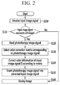
- FIG. 2 is a flowchart illustrating a method for controlling the display device.
- a timing controller 100 receives an input image signal IS from an application processor 200 (S100). Then, the timing controller 100 determines whether the input image signal represents a still image or not (S110). The timing controller 100 compares a pixel value of each of the sub-images of the current frame image with that of each of the corresponding sub-images of a previous frame image, and determines that the sub-image represents still image, which is a motionless image, if a difference between the pixel values is below a predetermined threshold value, and represents a moving image if the difference between the pixel values exceeds a predetermined threshold value.
- the timing controller 100 reads a phototherapy image signal T_IS from a memory 140 (S120).
- the timing controller 100 may read the phototherapy image signal T_IS for displaying light of a specific wavelength.
- the timing controller 100 may then select a color correction matrix corresponding to a phototherapy image from the memory 140 (S130), and may calculate the corrected or compensated input image signal IS using the color correction matrix (S140). For example, the timing controller 100 may correct the color of input image IS by multiplying the R, G, B vector component of input image IS by the color correction matrix.
- the timing controller 100 may calculate the input image signal IS and the color correction matrix in consideration of a display time of the input image frame and a display time of the phototherapy image frame.
- the timing controller 100 then inserts the phototherapy image signal T_IS into the corrected input image signal IS (S150).
- the timing controller 100 may insert the phototherapy image frame between the corrected input image frames. This will be described together with reference to FIGS. 3 and 4 .
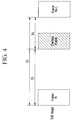
- FIGS. 3 and 4 are drawings illustrating an example of inserting a phototherapy image into an input image according to an embodiment of the invention.
- a period for sequentially displaying a plurality of image frames may be T1.
- an interval between the image frames of the continuous still image may be a period T2 that is greater than period T1.
- the phototherapy image frame may be inserted between the image frames of the still image.
- the phototherapy image frame is inserted between an N-th image frame and an (N+1)-th image frame of a still image.
- An interval between the N-th image frame and the phototherapy image frame may be a period T3 that is greater than T1. Also, an interval between the phototherapy image frame and the (N+1)-th image frame may be a period T4 that is smaller than T3.
- a color correction matrix may be calculated with the input image signal IS in consideration of a ratio of period T3 to period T4. For example, as a difference between periods T3 and T4 grows smaller, a display time of the phototherapy image frame increases. Then, a patient recognizes a color of the display image as being further distorted. Accordingly, an input matrix value when the difference between periods T3 and T4 is "a”, is greater than that when the difference between periods T3 and T4 is "b" (a > b).
- the timing controller 100 outputs the signals such that the color-corrected input image frame, and the inserted phototherapy image frame, are sequentially displayed on the display unit 130 (S160).
- FIGS. 5 to 7 are drawings illustrating a method for controlling wavelengths of a phototherapy image according to another embodiment of the invention.
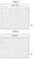
- an application processor 200 outputs a phototherapy control signal CONTS to a timing controller 100 according to a current time, thereby displaying light of a specific wavelength on a display unit 130 according to the time.
- the application processor 200 may output the phototherapy control signal CONTS such that the display unit 130 substantially displays light of an approximate wavelength of 464 nm from 06 hrs. to 17 hrs.
- the timing controller 100 reads a phototherapy image signal for displaying light of 464 nm wavelength from the memory 140, and may output signals such that when a still image signal is received, the phototherapy image and the still image are mixed and displayed on the display unit 130.
- the application processor 200 may output the phototherapy control signal CONTS such that the display unit 130 displays light of an approximate wavelength of 440 nm from 20 hrs. to 06 hrs.
- the timing controller 100 reads the phototherapy image signal for displaying light of 444 nm wavelength from the memory 140, and may output signals such that when the still image signal is received, the phototherapy image and the still image are displayed in mixed manner (e.g., in alternating manner) on the display unit 130.
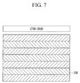
- the application processor 200 may output the phototherapy control signal CONTS such that the display unit 130 displays 464 nm and 440 nm light in spatially alternating manner from 17 hrs. to 20 hrs.
- FIG. 7 shows a pattern of different-wavelength light being displayed in alternating horizontal strips, any pattern of any wavelengths of light is contemplated.
- the timing controller 100 reads the phototherapy image signal for displaying light of 464 nm wavelength and the phototherapy image signal for displaying light of 440 nm wavelength from the memory 140, and may output signals such that when a still image signal is received, the phototherapy images and the still image are mixed in alternating manner and displayed on the display unit 130.
- the phototherapy image frame for displaying light of 464 nm wavelength may be inserted between a first still image frame and a second still image frame
- the phototherapy image frame for displaying light of 440 nm wavelength may be inserted between the second still image frame and a third still image frame
- the 464 nm phototherapy image frame may be inserted between the third still image frame and a fourth still image frame, and so on.
- the timing controller 100 may generate one phototherapy image frame using the phototherapy image signal for displaying light of 464 nm wavelength and the phototherapy image signal for displaying light of 440 nm wavelength. For example, the timing controller 100 may generate the phototherapy image frame for alternately emitting light of the wavelength of 464 nm or 440nm according to pixel row. In addition, the timing controller 100 may insert the generated phototherapy image between the first and second still image frames.
- the present invention may be implemented as a code in a computer readable medium in which a program is recorded.
- the computer readable medium may include any and all kinds of recording devices in which data readable by a computer system are stored.
- An example of the computer readable medium may include a hard disk drive (HDD), a solid state disk (SSD), a silicon disk drive (SDD), a read only memory (ROM), a random access memory (RAM), a compact disk read only memory (CD-ROM), a magnetic tape, a floppy disk, an optical data storage, or the like, and may also include a medium implemented in a form of a carrier wave (for example, transmission through the Internet).
- the computer may also include the timing controller 100 of the terminal.
Landscapes
- Health & Medical Sciences (AREA)
- Engineering & Computer Science (AREA)
- Biomedical Technology (AREA)
- Public Health (AREA)
- Veterinary Medicine (AREA)
- Life Sciences & Earth Sciences (AREA)
- Animal Behavior & Ethology (AREA)
- General Health & Medical Sciences (AREA)
- Physics & Mathematics (AREA)
- Radiology & Medical Imaging (AREA)
- Nuclear Medicine, Radiotherapy & Molecular Imaging (AREA)
- Pathology (AREA)
- Acoustics & Sound (AREA)
- Psychology (AREA)
- Anesthesiology (AREA)
- Heart & Thoracic Surgery (AREA)
- Hematology (AREA)
- General Physics & Mathematics (AREA)
- Theoretical Computer Science (AREA)
- Control Of Indicators Other Than Cathode Ray Tubes (AREA)
Abstract
Description
- The present invention generally relates to flat panel display devices, and more specifically relates to a display device and associated control methods for facilitating treatment of a disease or disorder using light.
- Light exposure methods have been developed recently, for treatment of diseases or disorders. These treatment methods include a method of exposing a patient to light of a specific wavelength band, and a method of exposing a patient to light in combination with a drug therapy. Such treatment methods are typically referred to as a phototherapy.
- Phototherapy has been used, for example, for treatment of diseases such as jaundice of the newborn, acne, psoriasis, eczema, cancer, neurological disorders, seasonal affective disorder, depression, bulimia, hand tremor associated with Parkinson's disease, ulcers, and circadian rhythm maintenance disorders as well as other diseases, disorders, or illnesses. Phototherapy has been used to promote injury recovery, to promote relaxation, to improve fertility, to stimulate hair growth, and to reduce expression of cellulite and wrinkles.
- Some phototherapy devices have been developed for treatment of a specific disease. In general, these phototherapy devices are designed to transmit specifically controlled light to the patient. The phototherapy devices may use fluorescent lamps, halogen lamps, inorganic or organic light emitting diodes as a direct spot light, or in combination with optical fibers.
- The effectiveness of phototherapy is generally dependent on the intensity of light used, a surface area exposed to light, and a percentage of a light spectrum that includes an effective wavelength for treatment of diseases or disorders.
- The above information disclosed in this Background section is only for enhancement of understanding of the background and therefore it may contain information that does not form the prior art that is already known in this country to a person of ordinary skill in the art.
- Embodiments of the present invention seek to solve the aforementioned problems and other problems by providing a display device and a control method therefor, for enabling treatment of a specific disease or disorder by using light, and by providing a display device and a control method therefor for reducing distortion of a display image due to phototherapy.
- According to one aspect of the invention, a display device may include: a display unit including a plurality of pixels; and a controller arranged to receive an image signal comprising a plurality of image frames. If the certain of the image frames are determined to represent a still image, the controller is arranged to insert a sub-image frame between immediately successive image frames of the certain of the image frames, the sub-image frame allowing at least one of the plurality of pixels to emit light of a specified wavelength.
- The controller may be further constructed to separate a first one of the image frames into a plurality of sub-images, compare the plurality of sub-images with corresponding sub-images of a previous one of the image frames that is received before the first image frame, detect whether the compared sub-images differ from each other, and thereby determine whether the image signal represents the still image signal.
- The display device may further include a memory storing information corresponding to the specified wavelength of light to be emitted.
- The controller may be further arranged to receive a control signal for controlling insertion of the sub-image frame, and may read the information from the memory according to the control signal.
- The plurality of image frames may include immediately successive first and second image frames, and the controller may be further constructed to insert the sub-image frame such that an interval between the first image frame and the sub-image frame is greater than that between the sub-image frame and the second image frame.
- The control signal may include a signal directing the controller to selectively read the information corresponding to the specified wavelength.
- The controller may be further constructed to correct a color of the image signal at least partially according to the specified wavelength of the sub-image frame that is selected by the control signal.
- The controller may be further constructed to correct the color of the image signal at least partially according to a ratio of the interval between the first image frame and the sub-image frame to the interval between the sub-image frame and the second image frame.
- The memory may further store information corresponding to a color correction matrix for correcting the color of the image signal.
- The controller may be further constructed to read the information, and to insert ones of the sub-image frames between successive image frames.
- The control signal may include a signal for directing the controller such that the sub-image frame for emitting light of a wavelength corresponding to a specific time zone is displayed.
- A method of controlling a display device includes: receiving an image signal; determining whether the image signal represents a still image; and inserting, if the image signal is determined to represent a still image, a sub-image frame between immediately successive image frames, the sub-image frame allowing at least one of the plurality of pixels to emit light of a specified wavelength.
- The determining may further include: separating a first one of the image frames into a plurality of sub-images; and detecting whether the sub-images of successive image frames represent a still image, by comparing the sub-images of the first one of the image frames with the corresponding sub-images of a previous image frame.
- The method may further include: receiving a control signal for controlling insertion of the sub-image frame; and reading, from a memory, information corresponding to a specified wavelength of light to be emitted according to the sub-image frame.
- The inserting may further include inserting the sub-image frame between successive first and second ones of the image frames so that an interval between the first image frame and the sub-image frame is greater than an interval between the sub-image frame and the second image frame.
- The reading may further include selectively reading the information from the memory.
- The method may further include correcting a color of the image signal according to the specified wavelength corresponding to the selectively read information.
- The correcting may further include correcting the color of the image signal at least partially according to a ratio of the interval between the first image frame and the sub-image frame to the interval between the sub-image frame and the second image frame.
- The information may correspond to multiple ones of the specified wavelengths.
- The inserting may further include respectively sequentially inserting multiple ones of the sub-image frames each between two immediately successive image frames.
- At least one of the exemplary embodiments may advantageously reduce distortion of displayed images and aid in treat specific diseases or disorders.
- An additional range of applicability will become clear from the following detailed description.
- At least some of the above and other features of the invention are set out in the claims.
- However, since various modifications and alternations within the spirit and scope of the invention may be clearly understood by those skilled in the art, it is to be understood that a detailed description and specific embodiments are provided only by way of example.
-
-
FIG. 1 is a block diagram of a display device related to an embodiment of the invention. -
FIG. 2 is a flowchart illustrating a method for controlling the display device related to an embodiment of the invention. -
FIGS. 3 and4 are drawings illustrating an example of inserting a phototherapy image into an input image according to an embodiment of the invention. -
FIGS. 5 to 7 are drawings illustrating a method for controlling wavelengths of a phototherapy image according to another embodiment of the invention. - Hereinafter, embodiments of the invention that are disclosed in the present specification will be described in detail with reference to the accompanying drawings. In the present specification, the same or similar components will be denoted by the same or similar reference numerals, and an overlapped description thereof will be omitted.
- Terms "module" and "unit" for components used in the following description are used only in order to easily make a specification. Therefore, these terms do not have meanings or roles that distinguish them from each other in themselves.
- Further, in describing embodiments of the present invention, when it is determined that a detailed description of the well-known art associated with the present invention may obscure the gist of the present invention, such detailed description may be omitted.
- In addition, the accompanying drawings are provided only in order to allow embodiments disclosed in the present specification to be easily understood and are not to be interpreted as limiting the invention, and it is to be understood that the present invention includes all modifications, equivalents, and substitutions without departing from the scope of the invention, as defined in the claims.
- Terms including ordinal numbers such as first, second, and the like, will be used only to describe various components, and are not interpreted as limiting these components.
- The terms are only used to differentiate one component from other components.
- It is to be understood that when one component is referred to as being "connected" or "coupled" to another component, it may be connected or coupled directly to another component or be connected or coupled to another component with the other component intervening therebetween.
- On the other hand, it is to be understood that when one component is referred to as being "connected or coupled directly" to another component, it may be connected to or coupled to another component without the other component intervening therebetween.
- Singular forms are to include plural forms unless the context clearly indicates otherwise.
- It will be further understood that terms "comprises" or "have" used in the present specification specify the presence of stated features, numerals, steps, operations, components, parts, or a combination thereof, but do not preclude the presence or addition of one or more other features, numerals, steps, operations, components, parts, or a combination thereof.
- The various Figures are not to scale. All numerical values are approximate, and may vary. All examples of specific materials and compositions are to be taken as nonlimiting only. Other suitable materials and compositions may be used instead.
- A display device described in the present specification may include digital TVs, mobile phones, smartphones, laptop computers, digital broadcasting terminals, personal digital assistants (PDAs), portable multimedia players (PMPs), navigation devices, slate PCs, tablet PCs, ultrabooks, wearable devices (e.g., watch-type terminals (smart watches), glasses type terminals (smart glasses), head mounted displays (HMDs), desktop computers, digital signages, etc.
-
FIG. 1 is a block diagram of a display device related to an embodiment of the invention. Referring toFIG. 1 , the display device includes adisplay unit 130 including a plurality of pixels PX, ascan driver 120, adata driver 110, atiming controller 100, and amemory 140. Further, the display device may be connected to anapplication processor 200. In addition, auser input unit 210 may be connected to theapplication processor 200. Theapplication processor 200 and theuser input unit 210 may be provided outside of the display device, or may be incorporated in the display device. - The constituent elements illustrated in
FIG. 1 are not essential for embodiment of the display device, so the display device described in the present specification may include more or fewer constituent elements than those described above. - The
display unit 130 is a display panel including a plurality of pixels PX that are connected to corresponding scan lines S1 to Sn and corresponding data lines D1 to Dm. - Each of the plurality of pixels PX displays an image in accordance with an image data signal that is transmitted to the corresponding pixels PX. The plurality of pixels PX included in the
display unit 130 are respectively connected to the plurality of scan lines S1 to Sn and the plurality of data lines D1 to Dm, and are arranged in an approximate matrix form. - The plurality of scan lines S1 to Sn substantially extends in a row direction such that, in the embodiment shown, they are almost parallel to each other.
- The data lines D1 to Dm substantially extend in a column direction such that, in this embodiment, they are almost parallel to each other.
- The
scan driver 120 is connected to thedisplay unit 130 via the plurality of scan lines S1 to Sn. Thescan driver 120 generates a plurality of scan signals for activating each pixel PX of thedisplay unit 130 according to a scan control signal CONT2, and transmits the scan signals to the corresponding scan lines S1 to Sn. - The scan control signal CONT2 is a signal for controlling an operation of the
scan driver 120, and is generated by thetiming controller 100. The scan control signal CONT2 may include a scan start signal, a clock signal CLK (not shown but included in CONT2 in, for example, known manner), etc. The scan start signal is a signal for generating a first scan signal for displaying one frame of an image. The clock signal CLK is a synchronization signal for sequentially applying the scan signals to the plurality of scan lines S1 to Sn. - The
data driver 110 is connected to each pixel PX of thedisplay unit 130 via the plurality of data lines D1 to Dm. Thedata driver 110 receives an image data signal DATA and transmits it to the corresponding data lines D1 to Dm according to a data control signal CONT1. - The data control signal CONT1 is a signal for controlling an operation of the
data driver 110, and is generated by thetiming controller 100. - The
data driver 110 selects a gray voltage according to the image data signal DATA, and transmits it as a data signal to the appropriate one of the data lines D1 to Dm. - The
timing controller 100 may receive an image signal IS that is received from theapplication processor 200, an input control signal for controlling display of the image signal IS, and a phototherapy control signal CONTS. - The image signal IS contains luminance information about each pixel PX of the
display unit 130, and luminance has a predetermined number of grays, for example, 1024, 256, or 64. - Examples of the input control signal transmitted to the
timing controller 100 are a vertical synchronization signal, a horizontal synchronization signal, a main clock signal MCLK, a data enable signal, etc. - The
timing controller 100 may display a phototherapy image on thedisplay unit 130 according to the phototherapy control signal CONTS. In particular, thetiming controller 100 may transmit a signal READ for reading the phototherapy image to thememory 140 and may also read a phototherapy image signal T_IS from thememory 140. Thetiming controller 100 may receive the image signal per frame and detect whether the image signal is a still image or not. Further, depending on whether the image signal is a still image or not, thetiming controller 100 may generate a signal for controlling the phototherapy image to be displayed in thedisplay unit 130. - More specifically, the
timing controller 100 separates a current frame image of a current input image into a plurality of sub-images. In addition, thetiming controller 100 compares the plurality of sub-images with corresponding sub-images of a previous frame image that is previously received, and detects whether each of the sub-images is different from its corresponding previous frame or not. - For example, the
timing controller 100 separates the frame image included in the input image signal into two sub-images, i.e., first and second sub-images, compares a pixel value of one of the sub-images with that of the corresponding sub-image of the previous frame image, and determines whether the sub-image as the still image, i.e. a motionless image, if a difference between the two pixel values is below a predetermined threshold value. Likewise, the image is determined to be a moving image if the difference between the pixel values exceeds a predetermined threshold value. - If the sub-image is determined to be a still image, the
timing controller 100 may read the phototherapy image signal T_IS from thememory 140, and mix it with the image signal to generate the image data signal DATA. Further, thetiming controller 100 appropriately image-processes the image signal IS and/or the phototherapy image signal T_IS such that they meet an operating condition of (e.g., are in the proper format for) thedisplay unit 130 and thedata driver 110 based on the image signal IS, the phototherapy image signal T_IS, the input control signal, and the phototherapy control signal CONTS that are received. - Specifically, the
timing controller 100 may generate the image data signal DATA by performing various image-processing processes on the image signal IS, such as gamma correction, luminance compensation, color correction, etc. - The
timing controller 100 may generate the image data signal DATA such that the image according to the image signal IS and the image according to the phototherapy image signal T_IS are appropriately mixed and displayed. In addition, thetiming controller 100 may correct a color of the image signal IS according to the phototherapy image signal T_IS. This will be described later with reference toFIG. 2 . - In addition, the
timing controller 100 transmits the scan control signal CONT2, for controlling the operation of thescan driver 120, to thescan driver 120. - The
timing controller 100 generates the data control signal CONT1 for controlling the operation of thedata driver 110, and transmits the data control signal CONT1 along with the previously image-processed image data signal DATA to thedata driver 110. - The
memory 140 stores color correction matrix values corresponding to a plurality of phototherapy image signals T_IS, and also stores each of the phototherapy images. - According to the phototherapy image signal T_IS that is read from the
memory 140, thetiming controller 100 may calculate the corresponding color correction matrix value with the image signal, to correct the color of the image signal. - The color correction matrix values are different depending on wavelengths of the respective phototherapy images.
- When one image frame of the phototherapy image for displaying light of a specific wavelength is inserted between the image frames of the display image, a color mixture between the phototherapy image and the display image may occur. That is, affected by light of a specific wavelength, a patient (or user) may recognize the color of the display image as being distorted. In other words, the inserted phototherapy images may change the perceived color of the display image.
- Thus, a color correction matrix value that depends on the wavelength of the phototherapy image is output to the
timing controller 100, and is used to modify or compensate the image signal, thereby preventing distortion of the display image. - The
memory 140 may include at least one of a flash memory, a hard disk, a solid state disk (SSD), a silicon disk drive (SDD), a micro-type multimedia card, a card-type memory (e.g., SD or XD memory), random access memory (RAM), static random access memory (SRAM), read-only memory (ROM), electrically erasable programmable read-only memory (EEPROM), programmable read-only memory (PROM), a magnetic memory, a magnetic disk, and an optical disk. Any form of information storage is contemplated. - The
application processor 200 outputs the image signal IS, the input control signal, and the phototherapy control signal CONTS to thetiming controller 100. While being connected to theuser input unit 210, theapplication processor 200 may generate signals according to user-input information (UIS), and output the signals to thetiming controller 100. - The
application processor 200 may generate the phototherapy control signal CONTS according to the user-input information (UIS). For example, theapplication processor 200 may generate the phototherapy control signal CONTS such that thedisplay unit 130 initiates display of the phototherapy image for displaying light of the specific wavelength. As another example, theapplication processor 200 may generate the phototherapy control signal CONTS such that thedisplay unit 130 initiates display of the phototherapy image for displaying light of the specific wavelength according to a specific time zone. - The user input unit 210 (e.g., touch key, mechanical key, microphone, etc.) is designed for receiving information from a user, and transmits the user-input information (UIS) to the
application processor 200. For example, theuser input unit 210 may receive a gesture, a voice input, and a command input of a user who wants to display the phototherapy image on the display device. Then, theuser input unit 210 may generate the corresponding user-input information (UIS) and transmit it to theapplication processor 200. - Embodiments related to a control method that can be realized in the display device configured as described above will now be described with reference to the accompanying drawings.
-
FIG. 2 is a flowchart illustrating a method for controlling the display device. As described above, atiming controller 100 receives an input image signal IS from an application processor 200 (S100). Then, thetiming controller 100 determines whether the input image signal represents a still image or not (S110). Thetiming controller 100 compares a pixel value of each of the sub-images of the current frame image with that of each of the corresponding sub-images of a previous frame image, and determines that the sub-image represents still image, which is a motionless image, if a difference between the pixel values is below a predetermined threshold value, and represents a moving image if the difference between the pixel values exceeds a predetermined threshold value. - Next, if the image signal is determined to be a still image, the
timing controller 100 reads a phototherapy image signal T_IS from a memory 140 (S120). In this case, according to a phototherapy control signal CONTS that is received from theapplication processor 200, thetiming controller 100 may read the phototherapy image signal T_IS for displaying light of a specific wavelength. Thetiming controller 100 may then select a color correction matrix corresponding to a phototherapy image from the memory 140 (S130), and may calculate the corrected or compensated input image signal IS using the color correction matrix (S140). For example, thetiming controller 100 may correct the color of input image IS by multiplying the R, G, B vector component of input image IS by the color correction matrix. - The
timing controller 100 may calculate the input image signal IS and the color correction matrix in consideration of a display time of the input image frame and a display time of the phototherapy image frame. - The
timing controller 100 then inserts the phototherapy image signal T_IS into the corrected input image signal IS (S150). Thetiming controller 100 may insert the phototherapy image frame between the corrected input image frames. This will be described together with reference toFIGS. 3 and4 . -
FIGS. 3 and4 are drawings illustrating an example of inserting a phototherapy image into an input image according to an embodiment of the invention. As described inFIG. 3 , when the input image signal IS is a moving image, a period for sequentially displaying a plurality of image frames may be T1. As shown inFIG. 4 , when the input image signal IS is a still image, an interval between the image frames of the continuous still image may be a period T2 that is greater than period T1. - The phototherapy image frame may be inserted between the image frames of the still image. In particular, the phototherapy image frame is inserted between an N-th image frame and an (N+1)-th image frame of a still image.
- An interval between the N-th image frame and the phototherapy image frame may be a period T3 that is greater than T1. Also, an interval between the phototherapy image frame and the (N+1)-th image frame may be a period T4 that is smaller than T3.
- A color correction matrix may be calculated with the input image signal IS in consideration of a ratio of period T3 to period T4. For example, as a difference between periods T3 and T4 grows smaller, a display time of the phototherapy image frame increases. Then, a patient recognizes a color of the display image as being further distorted. Accordingly, an input matrix value when the difference between periods T3 and T4 is "a", is greater than that when the difference between periods T3 and T4 is "b" (a > b). The
timing controller 100 outputs the signals such that the color-corrected input image frame, and the inserted phototherapy image frame, are sequentially displayed on the display unit 130 (S160). - Next, a method of displaying light of different wavelengths according to time zones will be described with reference to
FIGS. 5 to 7. FIGS. 5 to 7 are drawings illustrating a method for controlling wavelengths of a phototherapy image according to another embodiment of the invention. - According to the current exemplary embodiment, an
application processor 200 outputs a phototherapy control signal CONTS to atiming controller 100 according to a current time, thereby displaying light of a specific wavelength on adisplay unit 130 according to the time. - As shown in
FIG. 5 , theapplication processor 200 may output the phototherapy control signal CONTS such that thedisplay unit 130 substantially displays light of an approximate wavelength of 464 nm from 06 hrs. to 17 hrs. - When the phototherapy control signal CONTS is received, the
timing controller 100 reads a phototherapy image signal for displaying light of 464 nm wavelength from thememory 140, and may output signals such that when a still image signal is received, the phototherapy image and the still image are mixed and displayed on thedisplay unit 130. - As shown in
FIG. 6 , theapplication processor 200 may output the phototherapy control signal CONTS such that thedisplay unit 130 displays light of an approximate wavelength of 440 nm from 20 hrs. to 06 hrs. - When the phototherapy control signal CONTS is received, the
timing controller 100 reads the phototherapy image signal for displaying light of 444 nm wavelength from thememory 140, and may output signals such that when the still image signal is received, the phototherapy image and the still image are displayed in mixed manner (e.g., in alternating manner) on thedisplay unit 130. - In addition, as shown in
FIG. 7 , theapplication processor 200 may output the phototherapy control signal CONTS such that thedisplay unit 130 displays 464 nm and 440 nm light in spatially alternating manner from 17 hrs. to 20 hrs. AlthoughFIG. 7 shows a pattern of different-wavelength light being displayed in alternating horizontal strips, any pattern of any wavelengths of light is contemplated. - When the phototherapy control signal CONTS is received, the
timing controller 100 reads the phototherapy image signal for displaying light of 464 nm wavelength and the phototherapy image signal for displaying light of 440 nm wavelength from thememory 140, and may output signals such that when a still image signal is received, the phototherapy images and the still image are mixed in alternating manner and displayed on thedisplay unit 130. - For example, the phototherapy image frame for displaying light of 464 nm wavelength may be inserted between a first still image frame and a second still image frame, the phototherapy image frame for displaying light of 440 nm wavelength may be inserted between the second still image frame and a third still image frame, the 464 nm phototherapy image frame may be inserted between the third still image frame and a fourth still image frame, and so on.
- Alternatively, the
timing controller 100 may generate one phototherapy image frame using the phototherapy image signal for displaying light of 464 nm wavelength and the phototherapy image signal for displaying light of 440 nm wavelength. For example, thetiming controller 100 may generate the phototherapy image frame for alternately emitting light of the wavelength of 464 nm or 440nm according to pixel row. In addition, thetiming controller 100 may insert the generated phototherapy image between the first and second still image frames. - The present invention may be implemented as a code in a computer readable medium in which a program is recorded. The computer readable medium may include any and all kinds of recording devices in which data readable by a computer system are stored. An example of the computer readable medium may include a hard disk drive (HDD), a solid state disk (SSD), a silicon disk drive (SDD), a read only memory (ROM), a random access memory (RAM), a compact disk read only memory (CD-ROM), a magnetic tape, a floppy disk, an optical data storage, or the like, and may also include a medium implemented in a form of a carrier wave (for example, transmission through the Internet).
- In addition, the computer may also include the
timing controller 100 of the terminal. - Therefore, the above detailed description is not to be interpreted as being restrictive, but is to be considered as being illustrative. The scope is to be determined by reasonable interpretation of the claims, and all alterations within equivalences fall within the scope. Furthermore, different features of the various embodiments, disclosed or otherwise understood, can be mixed and matched in any manner to produce further embodiments within the scope of the invention.
Claims (11)
- A display device comprising:a display unit including a plurality of pixels; anda controller arranged to receive an image signal comprising a plurality of image frames and then, if certain of the image frames are determined to represent a still image, to insert a sub-image frame between immediately successive image frames of the certain of the image frames, the sub-image frame allowing at least one of the plurality of pixels to emit light of a specified wavelength.
- A display device according to claim 1, wherein the controller is further constructed to separate a first one of the image frames into a plurality of sub-images, to compare the plurality of sub-images with corresponding sub-images of a previous one of the image frames that is received before the first image frame, to detect whether the compared sub-images differ from each other, and to thereby determine whether the image signal represents the still image.
- A display device according to claim 1 or 2, further comprising a memory storing information corresponding to the specified wavelength of light to be emitted.
- A display device according to claim 3, wherein the controller is further arranged to receive a control signal for controlling insertion of the sub-image frame, and to read the information from the memory according to the control signal.
- A display device according to claim 4, wherein the plurality of image frames includes immediately successive first and second image frames, and the controller is further constructed to insert the sub-image frame such that an interval between the first image frame and the sub-image frame is greater than that between the sub-image frame and the second image frame.
- A display device according to claim 5, wherein the control signal includes a signal directing the controller to selectively read the information corresponding to the specified wavelength.
- A display device according to claim 6, wherein the controller is further constructed to correct a color of the image signal at least partially according to the specified wavelength of the sub-image frame that is selected by the control signal.
- A display device according to claim 7, wherein the controller is further constructed to correct the color of the image signal at least partially according to a ratio of the interval between the first image frame and the sub-image frame to the interval between the sub-image frame and the second image frame.
- A display device according to claim 7, wherein the memory further stores information corresponding to a color correction matrix for correcting the color of the image signal.
- A display device according to one of claims 6 to 9, wherein the controller is further constructed to read the information, and to insert ones of the sub-image frames between successive image frames.
- A display device according to one of claims 4 to 10, wherein the control signal includes a signal for directing the controller such that the sub-image frame for emitting light of a wavelength corresponding to a specific time zone is displayed.
Applications Claiming Priority (1)
| Application Number | Priority Date | Filing Date | Title |
|---|---|---|---|
| KR1020140158972A KR102289437B1 (en) | 2014-11-14 | 2014-11-14 | Display device and method for controlling the same |
Publications (2)
| Publication Number | Publication Date |
|---|---|
| EP3020440A1 true EP3020440A1 (en) | 2016-05-18 |
| EP3020440B1 EP3020440B1 (en) | 2018-01-10 |
Family
ID=54843583
Family Applications (1)
| Application Number | Title | Priority Date | Filing Date |
|---|---|---|---|
| EP15194245.5A Active EP3020440B1 (en) | 2014-11-14 | 2015-11-12 | Phototherapy display device |
Country Status (4)
| Country | Link |
|---|---|
| US (1) | US9950186B2 (en) |
| EP (1) | EP3020440B1 (en) |
| KR (1) | KR102289437B1 (en) |
| CN (1) | CN105609031B (en) |
Families Citing this family (2)
| Publication number | Priority date | Publication date | Assignee | Title |
|---|---|---|---|---|
| KR102285889B1 (en) * | 2019-06-25 | 2021-08-03 | 백승빈 | Service apparatus for retina cure, and control method thereof |
| WO2021152814A1 (en) * | 2020-01-31 | 2021-08-05 | シャープ株式会社 | Display device and method for driving same |
Citations (3)
| Publication number | Priority date | Publication date | Assignee | Title |
|---|---|---|---|---|
| US20140313245A1 (en) * | 2013-04-17 | 2014-10-23 | Samsung Display Co., Ltd. | Display device for reducing dynamic false contour |
| US20150217130A1 (en) * | 2014-02-03 | 2015-08-06 | Skylit Corporation | Systems and methods for phototherapy |
| JP2015196076A (en) * | 2014-03-31 | 2015-11-09 | 慶孝 大友 | Use of color light irradiation and colorant gaze and saliva ORP numerical combination device. |
Family Cites Families (22)
| Publication number | Priority date | Publication date | Assignee | Title |
|---|---|---|---|---|
| KR0131735B1 (en) | 1994-04-26 | 1998-04-16 | 배순훈 | Television with subliminal effects |
| GB2336931A (en) * | 1998-04-29 | 1999-11-03 | Sharp Kk | Temporal dither addressing scheme for light modulating devices |
| TW518552B (en) * | 2000-08-18 | 2003-01-21 | Semiconductor Energy Lab | Liquid crystal display device, method of driving the same, and method of driving a portable information device having the liquid crystal display device |
| TW541186B (en) | 2000-09-08 | 2003-07-11 | Koninkl Philips Electronics Nv | Method for controlling the alertness of a human subject and a light source for use in this method |
| JP2003114646A (en) * | 2001-08-03 | 2003-04-18 | Semiconductor Energy Lab Co Ltd | Display device and driving method thereof |
| WO2004088616A1 (en) | 2003-03-28 | 2004-10-14 | Sharp Kabushiki Kaisha | Display device |
| KR20050074946A (en) | 2005-06-27 | 2005-07-19 | 최철 | A method to lead human eeg using the after image effect |
| JP4971665B2 (en) * | 2006-03-31 | 2012-07-11 | 公立大学法人名古屋市立大学 | Phototherapy device for the treatment of skin diseases |
| US7443202B2 (en) * | 2006-06-02 | 2008-10-28 | Semiconductor Energy Laboratory Co., Ltd. | Semiconductor device and electronic apparatus having the same |
| DE102006060049B4 (en) * | 2006-06-27 | 2010-06-10 | Lg Display Co., Ltd. | Liquid crystal display and driving method |
| CN101106639A (en) * | 2006-07-11 | 2008-01-16 | 乐金电子(南京)等离子有限公司 | Residual image prevention method for image display device |
| US8400391B2 (en) * | 2008-01-10 | 2013-03-19 | Honeywell International Inc. | Method and system for improving dimming performance in a field sequential color display device |
| KR101589188B1 (en) * | 2008-11-20 | 2016-01-28 | 삼성디스플레이 주식회사 | Display device |
| JP5824676B2 (en) | 2009-09-29 | 2015-11-25 | パナソニックIpマネジメント株式会社 | LED illumination light source and illumination device |
| KR20110092630A (en) | 2010-02-10 | 2011-08-18 | 박세환 | Sebaceous gland disease treatment device that works on mobile devices |
| US10252051B2 (en) | 2010-07-01 | 2019-04-09 | Thomas Nichols | Handheld facial massage and light therapy device |
| KR20120052754A (en) * | 2010-11-16 | 2012-05-24 | 엘지전자 주식회사 | Image display device for having color and music therapy function and method of controlling the same |
| JPWO2012147772A1 (en) * | 2011-04-26 | 2014-07-28 | 株式会社ニコン | Image processing apparatus, image display apparatus, imaging apparatus, and program |
| JP2012242453A (en) * | 2011-05-16 | 2012-12-10 | Japan Display East Co Ltd | Display device |
| JP5883575B2 (en) * | 2011-05-16 | 2016-03-15 | ピクストロニクス,インコーポレイテッド | Display device and control method thereof |
| CN104077991B (en) * | 2013-03-25 | 2018-03-20 | 刘鸿达 | Display device and color temperature adjusting method thereof |
| CN103691069B (en) * | 2013-12-27 | 2018-10-30 | 固安翌光科技有限公司 | A kind of organic light emission physical therapy device |
-
2014
- 2014-11-14 KR KR1020140158972A patent/KR102289437B1/en active Active
-
2015
- 2015-11-11 CN CN201510769623.XA patent/CN105609031B/en active Active
- 2015-11-12 EP EP15194245.5A patent/EP3020440B1/en active Active
- 2015-11-12 US US14/939,814 patent/US9950186B2/en active Active
Patent Citations (3)
| Publication number | Priority date | Publication date | Assignee | Title |
|---|---|---|---|---|
| US20140313245A1 (en) * | 2013-04-17 | 2014-10-23 | Samsung Display Co., Ltd. | Display device for reducing dynamic false contour |
| US20150217130A1 (en) * | 2014-02-03 | 2015-08-06 | Skylit Corporation | Systems and methods for phototherapy |
| JP2015196076A (en) * | 2014-03-31 | 2015-11-09 | 慶孝 大友 | Use of color light irradiation and colorant gaze and saliva ORP numerical combination device. |
Also Published As
| Publication number | Publication date |
|---|---|
| KR102289437B1 (en) | 2021-08-12 |
| US9950186B2 (en) | 2018-04-24 |
| KR20160058325A (en) | 2016-05-25 |
| EP3020440B1 (en) | 2018-01-10 |
| CN105609031B (en) | 2020-10-27 |
| CN105609031A (en) | 2016-05-25 |
| US20160136449A1 (en) | 2016-05-19 |
Similar Documents
| Publication | Publication Date | Title |
|---|---|---|
| CN105877697B (en) | Electronic devices that provide images of biological effects | |
| TWI312431B (en) | Method and apparatus for driving liquid crystal display | |
| US9997096B2 (en) | Display apparatus, electronic device including the same, and method of operating the same | |
| US10366666B2 (en) | Display apparatus and method for controlling the same | |
| US10401955B2 (en) | Method for displaying an image and an electronic device thereof | |
| US20200243020A1 (en) | Display device and electronic device including a plurality of separately driven display areas and display control method for controlling the same | |
| US9830120B2 (en) | Methods and devices for processing images | |
| US20180211579A1 (en) | Display driving method according to display configuration and electronic device for supporting the same | |
| KR20180104940A (en) | Operating Method for Gamma Voltage corresponding to display configuration and electronic device supporting the same | |
| TW201241692A (en) | Display device having touch sensor and method for driving the same | |
| AU2017266815A1 (en) | Operating method for display corresponding to luminance, driving circuit, and electronic device supporting the same | |
| TW200530996A (en) | Method and apparatus for driving liquid crystal display device | |
| CN107111131A (en) | wearable electronics | |
| US11127332B2 (en) | Electronic device for controlling source driving of pixel on basis of characteristics of image, and image output method using electronic device | |
| EP2741276B1 (en) | Backlight driving method, backlight driving device, and display device | |
| EP3020440B1 (en) | Phototherapy display device | |
| CN105100760A (en) | Image processing method and image processing device for performing the same | |
| JP2018530795A (en) | Two-row driving method of micro display device | |
| US9524703B2 (en) | Method of operating an electronic device providing a bioeffect image | |
| US9235830B1 (en) | Establishing a reminder for an event in a calendar | |
| KR20240019053A (en) | Apparatus and method for treating mild cognitive impairment and dementia | |
| EP3259751B1 (en) | Display apparatus and method for controlling the same | |
| KR102398550B1 (en) | Touch display device and method of driving the same | |
| CN103123777B (en) | For driving equipment and the method for image display device | |
| KR102093187B1 (en) | Display device |
Legal Events
| Date | Code | Title | Description |
|---|---|---|---|
| PUAI | Public reference made under article 153(3) epc to a published international application that has entered the european phase |
Free format text: ORIGINAL CODE: 0009012 |
|
| AK | Designated contracting states |
Kind code of ref document: A1 Designated state(s): AL AT BE BG CH CY CZ DE DK EE ES FI FR GB GR HR HU IE IS IT LI LT LU LV MC MK MT NL NO PL PT RO RS SE SI SK SM TR |
|
| AX | Request for extension of the european patent |
Extension state: BA ME |
|
| 17P | Request for examination filed |
Effective date: 20161115 |
|
| RBV | Designated contracting states (corrected) |
Designated state(s): AL AT BE BG CH CY CZ DE DK EE ES FI FR GB GR HR HU IE IS IT LI LT LU LV MC MK MT NL NO PL PT RO RS SE SI SK SM TR |
|
| GRAP | Despatch of communication of intention to grant a patent |
Free format text: ORIGINAL CODE: EPIDOSNIGR1 |
|
| INTG | Intention to grant announced |
Effective date: 20170712 |
|
| GRAS | Grant fee paid |
Free format text: ORIGINAL CODE: EPIDOSNIGR3 |
|
| GRAA | (expected) grant |
Free format text: ORIGINAL CODE: 0009210 |
|
| AK | Designated contracting states |
Kind code of ref document: B1 Designated state(s): AL AT BE BG CH CY CZ DE DK EE ES FI FR GB GR HR HU IE IS IT LI LT LU LV MC MK MT NL NO PL PT RO RS SE SI SK SM TR |
|
| REG | Reference to a national code |
Ref country code: CH Ref legal event code: EP Ref country code: AT Ref legal event code: REF Ref document number: 961724 Country of ref document: AT Kind code of ref document: T Effective date: 20180115 |
|
| REG | Reference to a national code |
Ref country code: IE Ref legal event code: FG4D |
|
| REG | Reference to a national code |
Ref country code: DE Ref legal event code: R096 Ref document number: 602015007318 Country of ref document: DE |
|
| REG | Reference to a national code |
Ref country code: NL Ref legal event code: MP Effective date: 20180110 |
|
| REG | Reference to a national code |
Ref country code: AT Ref legal event code: MK05 Ref document number: 961724 Country of ref document: AT Kind code of ref document: T Effective date: 20180110 |
|
| PG25 | Lapsed in a contracting state [announced via postgrant information from national office to epo] |
Ref country code: NL Free format text: LAPSE BECAUSE OF FAILURE TO SUBMIT A TRANSLATION OF THE DESCRIPTION OR TO PAY THE FEE WITHIN THE PRESCRIBED TIME-LIMIT Effective date: 20180110 |
|
| PG25 | Lapsed in a contracting state [announced via postgrant information from national office to epo] |
Ref country code: HR Free format text: LAPSE BECAUSE OF FAILURE TO SUBMIT A TRANSLATION OF THE DESCRIPTION OR TO PAY THE FEE WITHIN THE PRESCRIBED TIME-LIMIT Effective date: 20180110 Ref country code: CY Free format text: LAPSE BECAUSE OF FAILURE TO SUBMIT A TRANSLATION OF THE DESCRIPTION OR TO PAY THE FEE WITHIN THE PRESCRIBED TIME-LIMIT Effective date: 20180110 Ref country code: LT Free format text: LAPSE BECAUSE OF FAILURE TO SUBMIT A TRANSLATION OF THE DESCRIPTION OR TO PAY THE FEE WITHIN THE PRESCRIBED TIME-LIMIT Effective date: 20180110 Ref country code: NO Free format text: LAPSE BECAUSE OF FAILURE TO SUBMIT A TRANSLATION OF THE DESCRIPTION OR TO PAY THE FEE WITHIN THE PRESCRIBED TIME-LIMIT Effective date: 20180410 Ref country code: FI Free format text: LAPSE BECAUSE OF FAILURE TO SUBMIT A TRANSLATION OF THE DESCRIPTION OR TO PAY THE FEE WITHIN THE PRESCRIBED TIME-LIMIT Effective date: 20180110 Ref country code: ES Free format text: LAPSE BECAUSE OF FAILURE TO SUBMIT A TRANSLATION OF THE DESCRIPTION OR TO PAY THE FEE WITHIN THE PRESCRIBED TIME-LIMIT Effective date: 20180110 |
|
| PG25 | Lapsed in a contracting state [announced via postgrant information from national office to epo] |
Ref country code: SE Free format text: LAPSE BECAUSE OF FAILURE TO SUBMIT A TRANSLATION OF THE DESCRIPTION OR TO PAY THE FEE WITHIN THE PRESCRIBED TIME-LIMIT Effective date: 20180110 Ref country code: AT Free format text: LAPSE BECAUSE OF FAILURE TO SUBMIT A TRANSLATION OF THE DESCRIPTION OR TO PAY THE FEE WITHIN THE PRESCRIBED TIME-LIMIT Effective date: 20180110 Ref country code: LV Free format text: LAPSE BECAUSE OF FAILURE TO SUBMIT A TRANSLATION OF THE DESCRIPTION OR TO PAY THE FEE WITHIN THE PRESCRIBED TIME-LIMIT Effective date: 20180110 Ref country code: RS Free format text: LAPSE BECAUSE OF FAILURE TO SUBMIT A TRANSLATION OF THE DESCRIPTION OR TO PAY THE FEE WITHIN THE PRESCRIBED TIME-LIMIT Effective date: 20180110 Ref country code: PL Free format text: LAPSE BECAUSE OF FAILURE TO SUBMIT A TRANSLATION OF THE DESCRIPTION OR TO PAY THE FEE WITHIN THE PRESCRIBED TIME-LIMIT Effective date: 20180110 Ref country code: GR Free format text: LAPSE BECAUSE OF FAILURE TO SUBMIT A TRANSLATION OF THE DESCRIPTION OR TO PAY THE FEE WITHIN THE PRESCRIBED TIME-LIMIT Effective date: 20180411 Ref country code: IS Free format text: LAPSE BECAUSE OF FAILURE TO SUBMIT A TRANSLATION OF THE DESCRIPTION OR TO PAY THE FEE WITHIN THE PRESCRIBED TIME-LIMIT Effective date: 20180510 Ref country code: BG Free format text: LAPSE BECAUSE OF FAILURE TO SUBMIT A TRANSLATION OF THE DESCRIPTION OR TO PAY THE FEE WITHIN THE PRESCRIBED TIME-LIMIT Effective date: 20180410 |
|
| REG | Reference to a national code |
Ref country code: DE Ref legal event code: R097 Ref document number: 602015007318 Country of ref document: DE |
|
| PG25 | Lapsed in a contracting state [announced via postgrant information from national office to epo] |
Ref country code: AL Free format text: LAPSE BECAUSE OF FAILURE TO SUBMIT A TRANSLATION OF THE DESCRIPTION OR TO PAY THE FEE WITHIN THE PRESCRIBED TIME-LIMIT Effective date: 20180110 Ref country code: EE Free format text: LAPSE BECAUSE OF FAILURE TO SUBMIT A TRANSLATION OF THE DESCRIPTION OR TO PAY THE FEE WITHIN THE PRESCRIBED TIME-LIMIT Effective date: 20180110 Ref country code: IT Free format text: LAPSE BECAUSE OF FAILURE TO SUBMIT A TRANSLATION OF THE DESCRIPTION OR TO PAY THE FEE WITHIN THE PRESCRIBED TIME-LIMIT Effective date: 20180110 Ref country code: RO Free format text: LAPSE BECAUSE OF FAILURE TO SUBMIT A TRANSLATION OF THE DESCRIPTION OR TO PAY THE FEE WITHIN THE PRESCRIBED TIME-LIMIT Effective date: 20180110 |
|
| REG | Reference to a national code |
Ref country code: FR Ref legal event code: PLFP Year of fee payment: 4 |
|
| PLBE | No opposition filed within time limit |
Free format text: ORIGINAL CODE: 0009261 |
|
| STAA | Information on the status of an ep patent application or granted ep patent |
Free format text: STATUS: NO OPPOSITION FILED WITHIN TIME LIMIT |
|
| PG25 | Lapsed in a contracting state [announced via postgrant information from national office to epo] |
Ref country code: SK Free format text: LAPSE BECAUSE OF FAILURE TO SUBMIT A TRANSLATION OF THE DESCRIPTION OR TO PAY THE FEE WITHIN THE PRESCRIBED TIME-LIMIT Effective date: 20180110 Ref country code: CZ Free format text: LAPSE BECAUSE OF FAILURE TO SUBMIT A TRANSLATION OF THE DESCRIPTION OR TO PAY THE FEE WITHIN THE PRESCRIBED TIME-LIMIT Effective date: 20180110 Ref country code: DK Free format text: LAPSE BECAUSE OF FAILURE TO SUBMIT A TRANSLATION OF THE DESCRIPTION OR TO PAY THE FEE WITHIN THE PRESCRIBED TIME-LIMIT Effective date: 20180110 Ref country code: SM Free format text: LAPSE BECAUSE OF FAILURE TO SUBMIT A TRANSLATION OF THE DESCRIPTION OR TO PAY THE FEE WITHIN THE PRESCRIBED TIME-LIMIT Effective date: 20180110 |
|
| 26N | No opposition filed |
Effective date: 20181011 |
|
| PG25 | Lapsed in a contracting state [announced via postgrant information from national office to epo] |
Ref country code: SI Free format text: LAPSE BECAUSE OF FAILURE TO SUBMIT A TRANSLATION OF THE DESCRIPTION OR TO PAY THE FEE WITHIN THE PRESCRIBED TIME-LIMIT Effective date: 20180110 |
|
| REG | Reference to a national code |
Ref country code: CH Ref legal event code: PL |
|
| PG25 | Lapsed in a contracting state [announced via postgrant information from national office to epo] |
Ref country code: MC Free format text: LAPSE BECAUSE OF FAILURE TO SUBMIT A TRANSLATION OF THE DESCRIPTION OR TO PAY THE FEE WITHIN THE PRESCRIBED TIME-LIMIT Effective date: 20180110 Ref country code: LU Free format text: LAPSE BECAUSE OF NON-PAYMENT OF DUE FEES Effective date: 20181112 |
|
| REG | Reference to a national code |
Ref country code: BE Ref legal event code: MM Effective date: 20181130 |
|
| REG | Reference to a national code |
Ref country code: IE Ref legal event code: MM4A |
|
| PG25 | Lapsed in a contracting state [announced via postgrant information from national office to epo] |
Ref country code: CH Free format text: LAPSE BECAUSE OF NON-PAYMENT OF DUE FEES Effective date: 20181130 Ref country code: LI Free format text: LAPSE BECAUSE OF NON-PAYMENT OF DUE FEES Effective date: 20181130 |
|
| PG25 | Lapsed in a contracting state [announced via postgrant information from national office to epo] |
Ref country code: IE Free format text: LAPSE BECAUSE OF NON-PAYMENT OF DUE FEES Effective date: 20181112 |
|
| PG25 | Lapsed in a contracting state [announced via postgrant information from national office to epo] |
Ref country code: BE Free format text: LAPSE BECAUSE OF NON-PAYMENT OF DUE FEES Effective date: 20181130 |
|
| PG25 | Lapsed in a contracting state [announced via postgrant information from national office to epo] |
Ref country code: MT Free format text: LAPSE BECAUSE OF NON-PAYMENT OF DUE FEES Effective date: 20181112 |
|
| PG25 | Lapsed in a contracting state [announced via postgrant information from national office to epo] |
Ref country code: TR Free format text: LAPSE BECAUSE OF FAILURE TO SUBMIT A TRANSLATION OF THE DESCRIPTION OR TO PAY THE FEE WITHIN THE PRESCRIBED TIME-LIMIT Effective date: 20180110 |
|
| PG25 | Lapsed in a contracting state [announced via postgrant information from national office to epo] |
Ref country code: PT Free format text: LAPSE BECAUSE OF FAILURE TO SUBMIT A TRANSLATION OF THE DESCRIPTION OR TO PAY THE FEE WITHIN THE PRESCRIBED TIME-LIMIT Effective date: 20180110 |
|
| PG25 | Lapsed in a contracting state [announced via postgrant information from national office to epo] |
Ref country code: MK Free format text: LAPSE BECAUSE OF NON-PAYMENT OF DUE FEES Effective date: 20180110 Ref country code: HU Free format text: LAPSE BECAUSE OF FAILURE TO SUBMIT A TRANSLATION OF THE DESCRIPTION OR TO PAY THE FEE WITHIN THE PRESCRIBED TIME-LIMIT; INVALID AB INITIO Effective date: 20151112 |
|
| P01 | Opt-out of the competence of the unified patent court (upc) registered |
Effective date: 20230515 |
|
| PGFP | Annual fee paid to national office [announced via postgrant information from national office to epo] |
Ref country code: DE Payment date: 20241021 Year of fee payment: 10 |
|
| PGFP | Annual fee paid to national office [announced via postgrant information from national office to epo] |
Ref country code: GB Payment date: 20241021 Year of fee payment: 10 |
|
| PGFP | Annual fee paid to national office [announced via postgrant information from national office to epo] |
Ref country code: FR Payment date: 20241022 Year of fee payment: 10 |