EP3020375B1 - Spinal fixation device - Google Patents
Spinal fixation device Download PDFInfo
- Publication number
- EP3020375B1 EP3020375B1 EP15194277.8A EP15194277A EP3020375B1 EP 3020375 B1 EP3020375 B1 EP 3020375B1 EP 15194277 A EP15194277 A EP 15194277A EP 3020375 B1 EP3020375 B1 EP 3020375B1
- Authority
- EP
- European Patent Office
- Prior art keywords
- fixation device
- outer housing
- spinal fixation
- end plate
- spinal
- Prior art date
- Legal status (The legal status is an assumption and is not a legal conclusion. Google has not performed a legal analysis and makes no representation as to the accuracy of the status listed.)
- Active
Links
Images








Classifications
-
- A—HUMAN NECESSITIES
- A61—MEDICAL OR VETERINARY SCIENCE; HYGIENE
- A61F—FILTERS IMPLANTABLE INTO BLOOD VESSELS; PROSTHESES; DEVICES PROVIDING PATENCY TO, OR PREVENTING COLLAPSING OF, TUBULAR STRUCTURES OF THE BODY, e.g. STENTS; ORTHOPAEDIC, NURSING OR CONTRACEPTIVE DEVICES; FOMENTATION; TREATMENT OR PROTECTION OF EYES OR EARS; BANDAGES, DRESSINGS OR ABSORBENT PADS; FIRST-AID KITS
- A61F2/00—Filters implantable into blood vessels; Prostheses, i.e. artificial substitutes or replacements for parts of the body; Appliances for connecting them with the body; Devices providing patency to, or preventing collapsing of, tubular structures of the body, e.g. stents
- A61F2/02—Prostheses implantable into the body
- A61F2/30—Joints
- A61F2/44—Joints for the spine, e.g. vertebrae or spinal discs
-
- A—HUMAN NECESSITIES
- A61—MEDICAL OR VETERINARY SCIENCE; HYGIENE
- A61F—FILTERS IMPLANTABLE INTO BLOOD VESSELS; PROSTHESES; DEVICES PROVIDING PATENCY TO, OR PREVENTING COLLAPSING OF, TUBULAR STRUCTURES OF THE BODY, e.g. STENTS; ORTHOPAEDIC, NURSING OR CONTRACEPTIVE DEVICES; FOMENTATION; TREATMENT OR PROTECTION OF EYES OR EARS; BANDAGES, DRESSINGS OR ABSORBENT PADS; FIRST-AID KITS
- A61F2/00—Filters implantable into blood vessels; Prostheses, i.e. artificial substitutes or replacements for parts of the body; Appliances for connecting them with the body; Devices providing patency to, or preventing collapsing of, tubular structures of the body, e.g. stents
- A61F2/02—Prostheses implantable into the body
- A61F2/30—Joints
- A61F2/44—Joints for the spine, e.g. vertebrae or spinal discs
- A61F2/4455—Joints for the spine, e.g. vertebrae or spinal discs for the fusion of spinal bodies, e.g. intervertebral fusion of adjacent spinal bodies, e.g. fusion cages
- A61F2/447—Joints for the spine, e.g. vertebrae or spinal discs for the fusion of spinal bodies, e.g. intervertebral fusion of adjacent spinal bodies, e.g. fusion cages substantially parallelepipedal, e.g. having a rectangular or trapezoidal cross-section
Definitions
- the present disclosure relates to an apparatus for treating spinal conditions, and more particularly, to an intervertebral implant.
- the human spine includes thirty-three vertebrae.
- the vertebrae interlock with one another to form a spinal column.
- Each vertebra has a cylindrical bony body (vertebral body), two pedicles extending from the vertebral body, a lamina extending from the pedicles, two wing-like projections extending from the pedicles, a spinous process extending from the lamina, a pars interarticularis, two superior facets extending from the pedicles, and two inferior facets extending from the lamina.
- the vertebrae are separated and cushioned by thin pads of tough, resilient fiber known as inter-vertebral discs. Inter-vertebral discs provide flexibility to the spine and act as shock absorbers during activity.
- a small opening (foramen) located in each vertebra allows passage of the spinal cord.
- the spinal cord passes through without a problem.
- nerves of the spinal cord may get compressed and may cause back pain, leg pain, or other neurological disorders.
- disorders of the spine that may cause misalignment of the vertebrae or constriction of the spinal canal include spinal injuries, infections, tumor formation, herniation of the inter-vertebral discs (i.e., slippage or protrusion), arthritic disorders, and scoliosis.
- surgery may be tried to either decompress the neural elements and/or fuse adjacent vertebral segments. Decompression may involve laminectomy, discectomy, or corpectomy.
- Laminectomy involves the removal of part of the lamina, i.e., the bony roof of the spinal canal.
- Discectomy involves removal of the inter-vertebral discs.
- Corpectomy involves removal of the vertebral body as well as the adjacent inter-vertebral discs.
- a number of spinal surgical devices may be used to promote bony fusion after decompressing the spinal nerves. For instance, surgeons often replace the diseased vertebral tissue with one or more spinal cages and bone support matrix. Spinal cages support adjacent vertebral segments, while furthering spinal fusion of adjacent vertebral bodies.
- scientists and clinicians have developed a number of devices and methods for decompressing spinal nerves. Improvements to these methods and devices are nevertheless still possible.
- U.S. Patent Publication No. 2014/0277503 filed on March 14, 2014 entitled "Spinal Fixation Device," for a detailed discussion of the construction and operation of a spinal fixation system and an instrumentation for use therewith.
- intervertebral spacer implants used as a stand-alone device or provided in an assembly including a retention mechanism to help alleviate expulsion and movement of the implant when placed in the spine, are well known.
- implant assemblies are advantageous in providing an implant that is easier to insert in the spine.
- Intervertebral spacer implant assemblies which include a spacer and a plate, where the plate comprises a supplemental or alternative retention mechanism having one or more holes in the anterior end of the plate that are directed toward the superior, inferior or both end plates of adjacent vertebrae are also known in the art.
- Such implants are used to stabilize and immobilize the spinal segments in the treatment of single or multi-level degenerative disc disease, spinal stenosis, and failed previous fusions, as well as other spine conditions.
- an spinal fixation device that can be secured to the spine and provide anterior column support and stabilization, while providing a maximum fusion area.
- a spinal fixation device comprising: an outer housing defining an aperture and a longitudinal axis; and an end plate assembly coupled with the outer housing, at least a portion of the end plate assembly slidably received within the outer housing, the end plate assembly including a first end plate configured to engage a vertebral body, wherein the end plate assembly is selectively movable between a first position in which the first end plate is spaced apart from the outer housing and a second position in which the first end plate is adjacent the outer housing, and the first end plate is selectively adjustable to an angular orientation of a plurality of angular orientations with respect to the longitudinal axis of the outer housing, wherein the end plate assembly includes first and second elongate members operatively coupled to the first end plate such that axial movement of the first and second elongate members in tandem causes axial displacement of the first end plate, and relative movement between the first and second elongate members transitions the first end plate from a first angular orientation to
- the mounting assembly may be releasably secured with the outer housing such that the end plate assembly is configured as a modular assembly interchangeably mounted in the outer housing. In particular configured so as to allow a clinician to interchange the end plate assembly with another end plate assembly.
- the mounting assembly may be releasably secured with the outer housing.
- the first and second rotatable members of the mounting assembly may be spaced apart from each other to define a gap therebetween.
- the device may comprise a spring pin received through a bore in the outer housing and through a transverse groove of the retaining housing to secure the retaining housing with the outer housing, such that when end plate assembly is pulled away from the outer housing, the spring pin flexes and disengages from the transverse groove to release the mounting assembly.
- each of the first and second rotatable members of the mounting assembly may include circumferentially arranged teeth opposing each other.
- the first rotatable member of the mounting assembly may include inner threads in a first orientation and the second rotatable member of the mounting assembly may include inner threads in a second orientation opposite to the first orientation.
- the outer housing may define a plurality of bores.
- at least one bore of the plurality of bores may be in communication with the gap defined between the first and second rotatable members of the mounting assembly.
- the plurality of bores may be circumferentially arranged about the outer housing.
- the plurality of bores may be arranged along a length of the outer housing.
- a surgical kit including a spinal fixation device and a surgical instrument or a rod connector or a drug delivery assembly or a shield as defined below.
- the spinal fixation device includes an outer housing and an end plate assembly.
- the end plate assembly is coupled with the outer housing. At least a portion of the end plate assembly is slidably received within the outer housing through an aperture of the outer housing.
- the end plate assembly includes a first end plate configured to engage a vertebral body, wherein the end plate assembly is selectively movable between a first position in which the first end plate is spaced apart from the outer housing and a second position in which the first end plate is adjacent the outer housing.
- the first end plate is selectively adjustable to an angular orientation of a plurality of angular orientations with respect to the outer housing.
- the surgical instrument defines a channel extending therethrough.
- the surgical instrument defines an engaging portion configured to securely engage the outer housing of the spinal fixation device.
- the surgical instrument may include a height adjusting driver rotatably extending through the channel of the surgical instrument.
- the height adjusting driver may include an engaging portion having teeth configured to engage the circumferentially arranged teeth of the first and second rotatable members of the mounting assembly, whereby rotation of the height adjusting driver causes rotation of the first and second rotatable members of the mounting assembly.
- the surgical instrument may further include an angle adjusting driver rotatably extending through the channel of the surgical instrument.
- the angle adjusting driver may include an engaging portion having teeth configured to engage the circumferentially arranged teeth of one of the first or second rotatable members of the mounting assembly, whereby rotation of the angle adjusting driver causes rotation of the one of the first or second rotatable members of the mounting assembly.
- the kit may include or further include a rod connector having an anchoring portion coupled with the outer housing of the spinal fixation device and a head portion having a recessed portion configured to receive a spinal rod.
- the rod connector may define a channel therethrough.
- the head portion of the rod connector may define a bore in communication with the channel.
- the rod connector may include the anchoring portion, a coupling portion rotatably and pivotably coupled with anchoring portion and a head portion.
- the anchoring portion may include an engaging portion threadably coupled with a bore of the outer housing.
- the anchoring portion and coupling portion may be coupled by ball and socket joint.
- the head portion may define slits configured to flex or enlarge the dimensions of recessed portion to facilitate insertion of the spinal rod.
- the head portion may further define a bore and a screw so that upon insertion of the spinal rod in the recessed portion, the screw is able to be fastened to secure the spinal rod in the recessed portion.
- the kit may further include a drug delivery assembly including a drug reservoir securely coupled with the outer housing of the spinal fixation device, a supply port, and a catheter in fluid communication with the supply port and the drug reservoir.
- the kit may further include a shield attachable to the spinal fixation device.
- the shield may be configured to reduce radiation to a spinal cord.
- the shield may include slow releasing medicament.
- proximal and distal may be employed interchangeably, and should be understood as referring to the portion of a structure that is closer to a clinician during proper use.
- distal and “leading” may also be employed interchangeably, and should be understood as referring to the portion of a structure that is farther from the clinician during proper use.
- cephalad or “cranial” is used in this application to indicate a direction toward a patient's head, whereas the term “caudad” indicates a direction toward the patient's feet.
- the term “medial” indicates a direction toward the middle of the body of the patient
- the term “lateral” indicates a direction toward a side of the body of the patient (i.e., away from the middle of the body of the patient).
- the term “posterior” indicates a direction toward the patient's back
- the term “anterior” indicates a direction toward the patient's front.
- spinal fixation device 500 configured and adapted to be positioned between vertebral bodies to support vertebral bodies and to promote spinal fusion.
- spinal fixation device 500 may be inserted into the patient laterally, posteriorly, anteriorly, or obliquely.
- spinal fixation device 500 may be inserted into the patient through procedures such as, e.g., posterior lumbar interbody fusion (PLIF), transforaminal lumbar interbody fusion (TLIF), lateral lumbar interbody fusion (LLIF), oblique lumbar interbody fusion (OLIF), or lateral extracavitary (LECA) procedures.
- PLIF posterior lumbar interbody fusion
- TLIF transforaminal lumbar interbody fusion
- LLIF lateral lumbar interbody fusion
- OLIF oblique lumbar interbody fusion
- LECA extracavitary
- Spinal fixation device 500 includes an outer housing 510 and an end plate assembly 560 interchangeably coupled with outer housing 510.
- Outer housing 510 includes a second end plate 550.
- End plate assembly 560 includes a first end plate 540, first and second elongate members 666, 668 operatively supporting first end plate 540, and a mounting assembly 600 operatively supporting first and second elongate members 666, 668.
- First and second end plates 540, 550 are configured to engage end plates of adjacent vertebral bodies.
- first and second end plates 540, 550 are configured to engage, e.g., endplates of superior and inferior vertebral bodies, respectively.
- Each of first and second end plates 540, 550 may include a plurality of pyramidal shaped spikes 533a, 533b (i.e., tetrahedrons) to aid in securing spinal fixation device 500 to the adjacent vertebral bodies for enhanced gripping of the vertebral bodies and minimizing movement of spinal fixation device 500 relative to the vertebral bodies.
- each of first and second end plates 540, 550 may include ridges or similar projections to aid in securing spinal fixation device 500 to the vertebral bodies.
- End plate assembly 560 is configured as a modular assembly that is interchangeably mounted in outer housing 510.
- a plurality of end plate assemblies 560 may be provided with varying parameters such as, e.g., footprint and lordosis, such that the clinician may selectively attach a desired end plate assembly 560 to outer housing 510 to meet the needs of each patient or surgical procedure being performed.
- end plate assembly 560 may be tailored to achieve a desired lordosis of a first end plate 540 and a desired axial spacing between outer housing 510 and first end plate 540, as will be discussed hereinbelow.
- Spinal fixation device 500 may be made of titanium, titanium alloy, stainless steel, allograft bone, autologous bone graft, polyetheretherketone (PEEK), cobalt chrome, polymeric materials, a combination thereof, or any other suitable biocompatible material.
- spinal fixation device 500 may be formed of bone, or an artificial material other than bone which may be harder or stronger than bone, such as, e.g., ceramic materials.
- Outer housing 510 may include a bone growth promoting material such as, e.g., bone morphogenic protein and hydroxyapatite. Outer housing 510 may define a cavity 551 to accommodate bone graft material therein.
- outer housing 510 includes first and second ends 524, 526 and an outer wall 512 extending between first and second ends 524, 526.
- Outer wall 512 defines a plurality of bores 521 configured to receive a screw 190 and operatively engage insertion instrument 6000 ( FIG. 10 ), as will be discussed hereinbelow. Bores 521 are circumferentially arranged about outer housing 510 to facilitate insertion of screw 190 and engagement with insertion instrument 6000 at different orientations.
- outer wall 512 further defines a plurality of bores 527 ( FIGS.
- outer housing 510 to facilitate fixation of spinal stabilization devices such as, e.g., a rod connector 1000 ( FIGS. 20a and 20b ), or a drug delivery assembly 1700 ( FIG. 25 ), as will be discussed hereinbelow.
- spinal stabilization devices such as, e.g., a rod connector 1000 ( FIGS. 20a and 20b ), or a drug delivery assembly 1700 ( FIG. 25 ), as will be discussed hereinbelow.
- the plurality of bores 527 may be defined in anterolateral portions of outer housing 510.
- first end 524 of outer housing 510 defines an aperture 522
- second end 526 of outer housing 510 includes second end plate 550, e.g., integrally formed, with outer housing 510.
- Outer housing 510 defines a chamber 520 configured to receive at least a portion of end plate assembly 560 through aperture 522.
- End plate assembly 560 is selectively positionable within chamber 520.
- End plate assembly 560 includes a mounting assembly 600 releasably supported on a shoulder 530 of first end 524 of outer housing 510.
- Mounting assembly 600 includes a retaining housing 602 including first and second housing halves 602a, 602b, first and second rotatable members 610, 612 rotatably supported in retaining housing 602, and first and second retaining rings 606, 608.
- aperture 522 of first end 524 of outer housing 510 includes a non-circular cross-section complementary to a transverse cross-section of a first end 615 of retaining housing 602 to inhibit rotation of retaining housing 602 in aperture 522.
- each of first and second housing halves 602a, 602b includes radially extending first and second protrusions 605, 607 configured to be received in respective first and second recesses 523, 525 defined in shoulder 530 of outer housing 510.
- Outer housing 510 defines a pair of bores 571 transverse to a longitudinal axis "A" ( FIG. 9 ) of spinal fixation device 500. Each bore 571 is configured to receive a spring pin 577.
- Each of first and second housing halves 602a, 602b defines a transverse groove 613 on respective second protrusions 607.
- Transverse groove 613 is configured to receive spring pin 577.
- spring pin 577 inserted through the respective bore 571 of outer housing 510 is received through transverse groove 613 of the respective second protrusion 607 to secure retaining housing 602 with outer housing 510.
- Spring pin 577 is flexible to enable the clinician to remove end plate assembly 560 from outer body 510 when end plate assembly 560 is pulled away from outer housing 510.
- spring pin 577 flexes and disengages from transverse groove 613 of second protrusion 607. In this manner, the clinician is able to interchangeably utilize various end plate assemblies 560.
- each of first and second housing halves 602a, 602b includes an inner wall 611 defining first and second circumferential grooves 630, 632 configured to receive at least a portion of first and second retaining rings 606, 608, respectively.
- First rotatable member 610 defines a circumferential groove 670 configured to support first retaining ring 606 therein.
- First retaining ring 606 extends radially outward from circumferential groove 670 of first rotatable member 610 such that at least a portion of first retaining ring 606 is received in first circumferential groove 630 of retaining housing 602. In this manner, first rotatable member 610 is rotatably supported within retaining housing 602.
- second rotatable member 612 defines a circumferential groove 672 configured to support second retaining ring 608 therein.
- Second retaining ring 608 extends radially outward from circumferential groove 672 such that at least a portion of second retaining ring 608 is received in second circumferential groove 632 of retaining housing 602.
- first and second rotatable members 610, 612 are rotatable with respect to retaining housing 602, while maintaining a fixed axial distance therebetween.
- First and second rotatable members 610, 612 include internal threads 609, 613 ( FIG. 6 ), respectively.
- internal threads 609, 613 are in opposite orientations, such that when first and second rotatable members 610, 612 rotate in opposite directions, the orientations of internal threads 609, 613 are the same.
- Internal threads 609, 613 are configured to threadably engage outer threads 662, 664 of first and second elongate members 666, 668 of end plate assembly 560, respectively. Under such a configuration, rotation of first and second rotatable members 610, 612 in opposite directions causes axial movement of first and second elongate members 666, 668 along longitudinal axis "A-A" ( FIG.
- first and second rotatable members 610, 612 include opposing teeth 682, 684, respectively. Teeth 682, 684 are configured to engage, e.g., an engaging portion 7030 of a height adjusting driver 7000 ( FIG. 13A ), as will be discussed hereinbelow. Under such a configuration, rotation of height adjusting driver 7000 operatively coupled with teeth 682, 684 causes rotation of first and second rotatable members 610, 612, which, in turn, causes axial movement of first and second elongate members 666, 668.
- end plate assembly 560 is selectively positionable relative to outer housing 510 through rotation of first and second rotatable members 610, 612 in opposite directions. In this manner, a length of spinal fixation device 500 may be selectively tailored to, e.g., the intervertebral space.
- first end plate 540 includes an underside 545 defining first and second grooves 547, 549.
- First and second grooves 547, 549 are configured to receive round head portions 666a, 668a of first and second elongate members 666, 668, respectively.
- Round head portions 666a, 668a define respective bores 666b, 668b.
- First end plate 540 further defines bores 541, 543 ( FIG. 7 ) configured to receive respective pins 611 ( FIG. 6 ). In this manner, pins 611 pivotably secure round head portions 666a, 668a to first end plate 540.
- first and second elongate members 666, 668 enable the clinician to adjust angular orientation of first end plate 540 with respect to longitudinal axis "A-A" ( FIG. 9 ) to achieve the desired lordosis, as will be discussed hereinbelow.
- First and second elongate members 666, 668 of end plate assembly 560 include outer threads 662, 664 configured to engage internal threads 609, 613 ( FIG. 6 ) of first and second rotatable members 602, 404.
- First and second elongate members 666, 668 of end plate assembly 560 are movable relative to each other along longitudinal axis "A-A".
- first end plate 540 may be advantageously angled to provide a desired amount of lordosis tailored to the need of each patient.
- first end plate 540 may be positioned substantially orthogonal to the longitudinal axis "A-A" ( FIG. 9 ) and adjacent first end 524 of outer housing 510.
- first end plate 540 may define an acute angle with longitudinal axis "A-A" ( FIG. 9 ) and spaced apart from first end 524.
- the clinician may use angle adjusting driver 8000 to adjust the relative positioning of first and second elongate members 666, 668 to provide the adequate amount of lordosis of first end plate 540, as will be described hereinbelow.
- Insertion instrument 6000 for use with spinal fixation device 500 to position spinal fixation device 500 between adjacent vertebral bodies.
- Insertion instrument 6000 includes a handle 6010 and an elongate body 6020 extending from handle 6010.
- Insertion instrument 6000 defines a channel 6035 ( FIG. 17 ) configured to receive a height adjusting driver 7000 (a distal end of height adjusting driver 700 shown in FIG. 17 ), an angle adjusting driver 8000 ( FIG. 18 ), or a tapered driver 9000 ( FIGS. 15A-C ) therethrough.
- Elongate body 6020 includes engaging portion 6032 ( FIG. 17 ) configured to, e.g., threadably, engage bore 521 of outer housing 510 to securely attach spinal fixation device 500 with insertion instrument 6000.
- Height adjusting driver 7000 configured to be received through channel 6035 ( FIG. 17 ) of insertion instrument 6000.
- Height adjusting driver 7000 includes a handle 7010, an elongate body 7020, and an engaging portion 7030.
- Engaging portion 7030 includes a plurality of teeth 7032 configured to engage teeth 684, 682 ( FIG. 6 ) of first and second rotatable members 610, 612 of mounting assembly 600, respectively.
- rotation of handle 7010 causes concomitant rotation of engaging portion 7030 about elongate body 7020, which, in turn, causes rotation of first and second rotatable members 610, 612 in opposite directions.
- Rotation of first and second rotatable members 610, 612 in opposite directions imparts axial translation of first and second elongate members 666, 668 as a single construct, which, in turn, enables the clinician to adjust the axial distance between first end plate 540 and outer housing 510, i.e., overall height of spinal fixation device 500.
- Rotation of handle 7010 in an opposite direction causes axial movement of end plate assembly 560 in an opposite direction.
- Angle adjusting driver 8000 configured to be received through channel 6035 ( FIG. 17 ) of insertion instrument 6000.
- Angle adjusting driver 8000 includes a handle 8010, an elongate body 8020, and an engaging portion 8030.
- engaging portion 8030 may be radially offset from a central axis "C-C" defined by elongate body 8020.
- Engaging portion 8030 includes a plurality of teeth 8034 configured to engage teeth 682, 684 ( FIG. 6 ) of either first or second rotatable members 610, 612 of mounting assembly 600. In this manner, rotation of handle 8010 causes rotation of one of the first or second rotatable members 610, 612 of mounting assembly 600.
- Rotation of only one rotatable member 610, 612 causes translation of one of first or second elongate member 666, 668.
- Relative movement between first and second elongate members 666, 668 changes angular orientation of first end plate 540 with respect to outer housing 510 and longitudinal axis "A-A.”
- the clinician may adjust the angular orientation of first end plate 540 to achieve the desired amount of lordosis or kyphosis.
- height adjusting driver 7000 and angle adjusting driver 8000 may be constructed as a single instrument that is configured to be received through channel 6035 ( FIG. 17 ) of insertion instrument 6000.
- a tapered driver 9000 configured to be received through channel 6035 ( FIG. 17 ) of insertion instrument 6000.
- Tapered driver 9000 includes a handle 9010, an elongate body 9020, and an engaging portion 9030.
- screws 190 may be positioned in bore 521 of outer housing 510 through channel 6035 of insertion instrument 6000.
- Teeth 9034 of engaging portion 9030 engage teeth on a head portion of screw 190. Under such a configuration, handle 9010 may be rotated to threadably secure screw 190 in bore 521.
- Rod connector 1000 may be used with spinal fixation device 500 to enhance securement of spinal fixation device 500 between vertebral bodies and to promote spinal fusion.
- Rod connector 1000 includes an anchoring portion 1010, a coupling portion 1020 rotatably and pivotably coupled with anchoring portion 1010, and a head portion 1030.
- Anchoring portion 1010 includes an engaging portion 1012 configured to be threadably coupled with bore 527 ( FIGS. 21a and 21b ) of spinal fixation device 500.
- Anchoring portion 1010 further includes a tip portion 1014 extending from engaging portion 1012. Tip portion 1014 has a diameter smaller than a diameter of engaging portion 1012 to facilitate alignment of engaging portion 1012 with bore 527.
- Anchoring portion 1010 further includes a ball joint 1016 ( FIG. 20b ).
- Coupling portion 1020 includes a socket 1022 configured to rotatably and pivotably receive ball joint 1016 of anchoring portion 1010. Under such a configuration, variable or polyaxial adjustments may be made between anchoring portion 1010 and coupling portion 1020. It is also contemplated that anchoring portion 1010 may include a socket and coupling portion 1020 may include a ball joint.
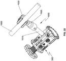
- Head portion 1030 includes a recessed portion 1032 configured to receive spinal rod 1500 therethrough. Head portion 1030 defines slits 1038 configured to flex or enlarge the dimensions of recessed portion 1032 to facilitate insertion of spinal rod 1500. Head portion 1030 further defines a bore 1034 ( FIG. 21a ) configured to receive a screw 1040. Upon insertion of spinal rod 1500 in recessed portion 1032, screw 1040 may be fastened to secure spinal rod 1500 in recessed portion 1032. With particular reference to FIG. 22 , spinal rod 1500 may be, e.g., a 5.5 mm diameter round rod. A reference may be made to U.S. Patent Application Serial No. 13/251,546 , now U.S. Patent No. 8,920,471, filed on October 3, 2011 , entitled "Transverse Connector," for a detailed discussion of the construction and operation of screws.
- spinal fixation device 500 may be tailored to a particular surgical procedure being performed.
- spinal fixation device 500' may include a plurality of bores 527' axially arranged along a length of spinal fixation device 500'.
- rod connector 1000 may be secured at a desired location along the length of spinal fixation device 500 to better secure spinal fixation device 500' between vertebral bodies v 1 , v 2 .
- additional rod connectors 1000 may be axially placed along the length of spinal fixation device 500' to further secure spinal fixation device 500'.
- pedicle screws 1600 may be secured to respective vertebral bodies v 1 , v 2 and at least one rod connector 1000 may be secured with spinal fixation device 500'.
- Spinal rod 1500 may be received through the pedicle screws and rod connector 1000.
- Screw 1040 is utilized to secure spinal rod 1500 in recessed portion 1032 of rod connector 1000 and set screws (not shown) are used to secure spinal rod 1500 with pedicle screws 1600.
- a pair of spinal rods 1500 may be utilized to further secure spinal fixation device 500' between vertebral bodies v 1 , v 2 .
- additional rod connectors 1000 may be axially placed along the length of spinal fixation device 500'.
- bores 527 may also be used to secure a drug delivery assembly 1700 to deliver a range of different synthetic or naturally occurring pharmaceutical or biological agents in liquid or gel formulations depending upon the particular application.
- Drugs may be administered for any actual or potential therapeutic, prophylactic or other medicinal purpose.
- Such drugs may include, e.g., analgesics, anesthetics, antimicrobial agents, antibodies, anticoagulants, antifibrinolytic agents, anti-inflammatory agents, antiparasitic agents, antiviral agents, cytokines, cytotoxins or cell proliferation inhibiting agents, chemotherapeutic agents, radiolabeled compounds or biologies, hormones, interferons, and combinations thereof.
- spinal fixation device 500 may be used to deliver a formulation comprising an agent used in chemotherapy or radiotherapy.
- Therapeutic agents may include chemotherapeutic agents (for example, paclitaxel, vincristine, ifosfamide, dacttinomycin, doxorubicin, cyclophosphamide, and the like), bisphosphonates (for example, alendronate, pamidronate, clodronate, zoledronic acid, and ibandronic acid), analgesics (such as opioids and NSAIDS), anesthetics (for example, ketoamine, bupivacaine and ropivacaine), tramadol, and dexamethasone.
- drug delivery assembly 1700 may be used for delivering an agent useful in radiotherapy in, e.g., beads.
- radioactive agents that are capable of targeting a particular tissue, antigen, or receptor type
- the radioactive agents are administered locally following implantation of spinal fixation device 500.
- radiotherapy agents include radiolabeled antibodies, radiolabeled peptide receptor ligands, or any other radiolabeled compound capable of specifically binding to the specific targeted cancer cells.
- drug delivery assembly 1700 may be used to deliver drugs used in the management of pain and swelling that occurs following the implantation surgery.
- spinal fixation device 500 may release an effective amount of an analgesic agent alone or in combination with an anesthetic agent.
- spinal fixation device 500 may be used to deliver drugs which help minimize the risk of infection following implantation.
- spinal fixation device 500 may release one or more antibiotics (for example, cefazolin, cephalosporin, tobramycin, gentamycin, etc.) and/or another agent effective in preventing or mitigating biofilms (for example, a quorum-sensing blocker or other agent targeting biofilm integrity).
- antibiotics for example, cefazolin, cephalosporin, tobramycin, gentamycin, etc.
- another agent effective in preventing or mitigating biofilms for example, a quorum-sensing blocker or other agent targeting biofilm integrity.
- Biofilms may form biofilms on the surface of spinal fixation device 500, and these biofilms may be relatively impermeable to antibiotics. Accordingly, systemically administered antibiotics may not achieve optimal dosing where it is most needed. However, spinal fixation device 500 enables the delivery of the desired dose of antibiotic precisely when and where needed. In certain circumstances, the antibiotic may be delivered beneath the biofilm.
- drug delivery assembly 1700 includes a drug reservoir 1720 secured with bore 527, a catheter 1730 in fluid communication with drug reservoir 1720, and a supply port 1740 in fluid communication with catheter 1730.
- Supply port 1740 may be affixed to a location most convenient for the patient or the clinician to supply the drugs using, e.g., syringe 1750.
- supply port 1740 may be affixed to an external location such as, e.g., the skin, of the patient.
- Supply port 1740 shown herein is merely exemplary and not drawn to scale.
- Supply port 1740 having different sizes, shapes, or profiles may be utilized for other applications such as, e.g., subcutaneous application.
- the drugs discussed hereinabove may be supplied through supply port 1740 by a syringe 1750. It is also contemplated that drug reservoir 1720 may be preloaded with a predetermined amount of drugs to eliminate catheter 1730, supply port 1740, and syringe 1750. It is further contemplated that spinal fixation device 500 may include channels, pores, and/or passages (not shown) formed in, e.g., outer housing 510. The channels, pores, and/or passages may be in fluid communication with drug reservoir 1720 to facilitate delivery of the drugs from drug reservoir 1720 to the delivery target.
- bores 527' of spinal fixation device 500' or alternatively, bores 527 of spinal fixation device 500 may also be used to secure a drug delivery assembly 1800 to deliver the drugs.
- Drug delivery assembly 1800 includes a cannula 1810 defining a channel 1820 therethrough.
- the drugs discussed hereinabove may be supplied to bores 527, 527' by syringe 1750 coupled to cannula 1810. It is contemplated that cannula 1810 may be coupled to spinal fixation device 500, 500' to supply the drugs to the delivery target during the surgical procedure and may be removed after the completion of the surgical procedure.
- a drug delivery assembly 1900 may be utilized to deliver the drugs to the delivery target.
- Drug delivery assembly 1900 includes rod connector 2000, a seal member 2060, a supply port 1940, and a catheter 1930 interconnecting supply port 1940 and rod connector 2000.
- rod connector 2000 defines a channel (not shown) extending therethrough such that when rod connector 2000 is coupled with spinal fixation device 500, 500', the channel is in fluid communication with bore 527, 527' of spinal fixation device 500, 500' to facilitate drug delivery through rod connector 2000.
- Rod connector 2000 has a substantially similar configuration as rod connector 1000. The portions of rod connector 2000 that are identical to rod connector 1000, as discussed hereinabove, will not be discussed in detail.
- Rod connector 2000 includes an anchoring portion 2010, a coupling portion 2020 rotatably and pivotably coupled with anchoring portion 2010, and a head portion 2030.
- Anchoring portion 2010 includes an engaging portion 2012 configured to be threadably coupled with bore 527 of spinal fixation device 500.
- Coupling portion 2020 is secured with head portion 2030.
- Head portion 2030 includes a recessed portion 2032 configured to receive spinal rod 1500 therethrough. Head portion 2030 defines slits 2038 configured to flex or enlarge the dimensions of recessed portion 2032 to facilitate insertion of spinal rod 1500.
- Head portion 1030 further defines a bore 2034 configured to receive screw 1040.
- rod connector 2000 may include a drug reservoir preloaded with a predetermined amount of drugs such that catheter 1930, supply port 1940, and seal member 2060 may be eliminated. Under such a configuration, a plug may be used to close bore 2050 in communication with the channel. In this manner, rod connector 2000 may provide, e.g., time-release, drug delivery.
- a drug delivery assembly 3000 may be utilized to deliver the drugs to the delivery target.
- drug delivery assembly 3000 includes a rod connector 3010, an engaging portion 3012, a seal member 3060, a supply port 3014, and catheters 3016a, 3016b.
- Rod connector 3010 is substantially identical to head portion 2030 of drug delivery assembly 1900, and thus, will not be described in detail herein.
- Rod connector 3010 includes a recessed portion 3032 configured to receive spinal rod 1500 therethrough.
- Rod connector 3010 defines slits 3038 configured to flex or enlarge the dimensions of recessed portion 3032 to facilitate insertion of spinal rod 1500.
- Rod connector 3010 further defines a bore 3034 configured to receive screw 1040.
- connecting rod 3010 defines a bore 3050.
- Bore 3050 is dimensioned to receive seal member 3060 in a sealing relation.
- Catheter 3016a connects bore 3050 with engaging portion 3012, and catheter 3016b interconnects supply port 3014 with seal member 3060.
- Engaging portion 3012 may be e.g., threadably, coupled with bore 527, 527' of spinal fixation device 500, 500'. Under such a configuration, when the patient or the clinician supplies the drugs to supply port 3014 using, e.g., syringe 1750 ( FIG.
- rod connector 3010 may include a drug reservoir preloaded with a predetermined amount of drugs such that catheter 3016b, supply port 3014, and seal member 3060 are eliminated. Under such a configuration, a plug (not shown) may be used to close bore 3050. In this manner, rod connector 3010 may provide, e.g., time-release, drug delivery.
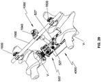
- a shield for use with spinal fixation device 500, 500' is generally shown as 4000.
- Shield 4000 may be affixed to spinal fixation device 500, 500' using adhesive, ultrasonic welding or other suitable means.
- Shield 4000 may include, e.g., polyphenylene sulfide (PPS), to reduce radiation to the spinal cord during, e.g., post-operative radiotherapy.
- PPS polyphenylene sulfide
- shield 4000 may serve as a barrier for bone cement such as, e.g., polymethyl methacrylate (PMMA), drugs, or bone graft products and biologics.
- shield 4000 may include, e.g., slow release agents such as antibiotics.
- the clinician first distracts vertebral bodies of interest to establish the intervertebral space.
- the clinician may then remove vertebral tissue, if necessary or desired.
- First and second elongate members 666, 668 of end plate assembly 560 are selectively positioned to achieve a desired orientation of first end plate 540.
- Insertion instrument 6000 is coupled with spinal fixation device 500 by, e.g., threadably, coupling engaging portion 6032 ( FIG. 17 ) with bore 521.
- Spinal fixation device 500 is then positioned adjacent a desired intervertebral space between vertebral bodies.
- height adjusting driver 7000 can be inserted through channel 6035 ( FIGS.
- insertion instrument 6000 to further adjust the axial distance between first end plate 560 and outer housing 510 by placing engaging portion 7030 through one of the plurality of bores 521 defined in outer housing 510 such that teeth 7032 of engaging portion 7030 of height adjusting driver 7000 engages teeth 684, 682 of first and second rotatable members 610, 612 of mounting assembly 600, respectively.
- rotation of handle 7010 causes rotation of first and second rotatable members 610, 612 in opposite directions, which, in turn, imparts axial translation of first and second elongate members 666, 668.
- the clinician may adjust the axial distance between first end plate 540 and outer housing 510, i.e., height of spinal fixation device 500.
- Handle 7010 is rotated until a desired height of spinal fixation device 500 is effected through axial movement of end plate assembly 560.
- angle adjusting driver 8000 can be inserted through channel 6035 ( FIG. 19 ) of insertion instrument 6000 to further adjust the angular orientation of first end plate 540 with respect to outer housing 510.
- Engaging portion 8030 is inserted through one of the plurality of bores 521 defined in outer housing 510 such that teeth 8034 of engaging portion 8030 of angle adjusting driver 8000 engages teeth 682 of first rotatable member 610 or teeth 684 of second rotatable member 612 of mounting assembly 600.
- Rotation of handle 8010 causes rotation of one of the first or second rotatable members 610, 612 of mounting assembly 600, which, in turn, causes translation of one of first or second elongate members 666, 668.
- Relative movement between first and second elongate members 666, 668 enables the clinician to adjust the angular orientation of first end plate 540 with respect to outer housing 510 to achieve the desired lordosis or kyphosis. It is contemplated that the clinician may make further adjustments by alternating height adjusting driver 7000 and angle adjusting driver 8000 to achieve the desired length of spinal fixation device 500 and angular orientation of first end plate 540.
- screw 190 may be placed in bore 521 defined in outer housing 510 through channel 6035 of insertion instrument 6000. Screw 190 may be threadably secured in bore 521 by using tapered driver 9000.
- rod connector 1000, pedicle screws 1600, and spinal rod 1500 may be utilized to further secure spinal fixation device 500 between vertebral bodies and to further promote spinal fusion.
- Anchoring portion 1010 of rod connector 1000 is threadably coupled with bore 527 of spinal fixation device 500, and pedicle screws 1600 are secured with respective vertebral bodies.
- spinal rod 1500 is inserted through recessed portion 1032 of rod connector 1000 and respective pedicle screws 1600.
- rod connector 1000 may be adjusted for proper angular orientation.
- Screw 1040 may be used to secure spinal rod 1500 in recessed portion 1032 of rod connector 1000 and the set screws (not shown) may be used to secure spinal rod 1500 with pedicle screws 1600.
- additional rod connector 1000 may be used to further secure spinal fixation device 500 between vertebral bodies.
- additional spinal rod 1500 may be utilized to further secure spinal fixation device 500 ( FIG. 24 ).
- drug delivery assemblies 1700, 1800, 1900, 3000 may be utilized to deliver the necessary drugs to the patient.
- drug reservoir 1720 of drug delivery assembly 1700 is secured with bore 527 of spinal fixation device 500.
- Supply port 1740 may be affixed to a location most convenient for the patient or the clinician to supply the drugs using, e.g., syringe 1750.
- cannula 1810 of drug delivery assembly 1800 is secured with bore 527 of spinal fixation device 500.
- the patient or the clinician may administer the drugs using syringe 1750.
- the use of drug delivery assemblies 1900, 2000 is substantially identical to the use of drug delivery assemblies 1700, 1800, and thus, will not be described herein.
- a drug pump such as, e.g., an insulin pump, may be connected to catheter 1730 to supply the drugs.
Landscapes
- Health & Medical Sciences (AREA)
- Engineering & Computer Science (AREA)
- Biomedical Technology (AREA)
- Orthopedic Medicine & Surgery (AREA)
- Neurology (AREA)
- Heart & Thoracic Surgery (AREA)
- Oral & Maxillofacial Surgery (AREA)
- Transplantation (AREA)
- Cardiology (AREA)
- Vascular Medicine (AREA)
- Life Sciences & Earth Sciences (AREA)
- Animal Behavior & Ethology (AREA)
- General Health & Medical Sciences (AREA)
- Public Health (AREA)
- Veterinary Medicine (AREA)
- Surgical Instruments (AREA)
- Prostheses (AREA)
Description
- The present disclosure relates to an apparatus for treating spinal conditions, and more particularly, to an intervertebral implant.
- The human spine includes thirty-three vertebrae. The vertebrae interlock with one another to form a spinal column. Each vertebra has a cylindrical bony body (vertebral body), two pedicles extending from the vertebral body, a lamina extending from the pedicles, two wing-like projections extending from the pedicles, a spinous process extending from the lamina, a pars interarticularis, two superior facets extending from the pedicles, and two inferior facets extending from the lamina. The vertebrae are separated and cushioned by thin pads of tough, resilient fiber known as inter-vertebral discs. Inter-vertebral discs provide flexibility to the spine and act as shock absorbers during activity. A small opening (foramen) located in each vertebra allows passage of the spinal cord. When the vertebrae are properly aligned, the spinal cord passes through without a problem. However, when the vertebrae are misaligned or a constriction is formed in the spinal canal, nerves of the spinal cord may get compressed and may cause back pain, leg pain, or other neurological disorders.
- Disorders of the spine that may cause misalignment of the vertebrae or constriction of the spinal canal include spinal injuries, infections, tumor formation, herniation of the inter-vertebral discs (i.e., slippage or protrusion), arthritic disorders, and scoliosis. In these pathologic circumstances, surgery may be tried to either decompress the neural elements and/or fuse adjacent vertebral segments. Decompression may involve laminectomy, discectomy, or corpectomy. Laminectomy involves the removal of part of the lamina, i.e., the bony roof of the spinal canal. Discectomy involves removal of the inter-vertebral discs. Corpectomy involves removal of the vertebral body as well as the adjacent inter-vertebral discs.
- A number of spinal surgical devices may be used to promote bony fusion after decompressing the spinal nerves. For instance, surgeons often replace the diseased vertebral tissue with one or more spinal cages and bone support matrix. Spinal cages support adjacent vertebral segments, while furthering spinal fusion of adjacent vertebral bodies. Scientists and clinicians have developed a number of devices and methods for decompressing spinal nerves. Improvements to these methods and devices are nevertheless still possible. Reference may be made to
U.S. Patent Publication No. 2014/0277503 filed on March 14, 2014 , entitled "Spinal Fixation Device," for a detailed discussion of the construction and operation of a spinal fixation system and an instrumentation for use therewith. - Furthermore, intervertebral spacer implants used as a stand-alone device or provided in an assembly including a retention mechanism to help alleviate expulsion and movement of the implant when placed in the spine, are well known. Such implant assemblies are advantageous in providing an implant that is easier to insert in the spine. Intervertebral spacer implant assemblies which include a spacer and a plate, where the plate comprises a supplemental or alternative retention mechanism having one or more holes in the anterior end of the plate that are directed toward the superior, inferior or both end plates of adjacent vertebrae are also known in the art. Such implants are used to stabilize and immobilize the spinal segments in the treatment of single or multi-level degenerative disc disease, spinal stenosis, and failed previous fusions, as well as other spine conditions.
- To meet the problem of preventing expulsion of the interbody device and for providing stability to the anatomy, a need exists for an spinal fixation device that can be secured to the spine and provide anterior column support and stabilization, while providing a maximum fusion area.
- Documents cited during prosecution include
US 2014/0277503 A1 , which discloses a spinal fixation device, upon which document the two-part form ofClaim 1 is based. - In accordance with an embodiment of the present disclosure, there is provided a spinal fixation device comprising: an outer housing defining an aperture and a longitudinal axis; and an end plate assembly coupled with the outer housing, at least a portion of the end plate assembly slidably received within the outer housing, the end plate assembly including a first end plate configured to engage a vertebral body, wherein the end plate assembly is selectively movable between a first position in which the first end plate is spaced apart from the outer housing and a second position in which the first end plate is adjacent the outer housing, and the first end plate is selectively adjustable to an angular orientation of a plurality of angular orientations with respect to the longitudinal axis of the outer housing, wherein the end plate assembly includes first and second elongate members operatively coupled to the first end plate such that axial movement of the first and second elongate members in tandem causes axial displacement of the first end plate, and relative movement between the first and second elongate members transitions the first end plate from a first angular orientation to a second angular orientation, and wherein the spinal fixation device further comprises a mounting assembly operatively supporting the first and second elongate members in the outer housing, characterized in that the mounting assembly includes a retaining housing and first and second rotatable members rotatably supported in the retaining housing, the first and second rotatable members operatively coupled with the first and second elongate members of the end plate assembly.
- The mounting assembly may be releasably secured with the outer housing such that the end plate assembly is configured as a modular assembly interchangeably mounted in the outer housing. In particular configured so as to allow a clinician to interchange the end plate assembly with another end plate assembly.
- The mounting assembly may be releasably secured with the outer housing. The first and second rotatable members of the mounting assembly may be spaced apart from each other to define a gap therebetween.
- The device may comprise a spring pin received through a bore in the outer housing and through a transverse groove of the retaining housing to secure the retaining housing with the outer housing, such that when end plate assembly is pulled away from the outer housing, the spring pin flexes and disengages from the transverse groove to release the mounting assembly.
- In an embodiment, each of the first and second rotatable members of the mounting assembly may include circumferentially arranged teeth opposing each other. The first rotatable member of the mounting assembly may include inner threads in a first orientation and the second rotatable member of the mounting assembly may include inner threads in a second orientation opposite to the first orientation.
- The outer housing may define a plurality of bores. In particular, at least one bore of the plurality of bores may be in communication with the gap defined between the first and second rotatable members of the mounting assembly. The plurality of bores may be circumferentially arranged about the outer housing. The plurality of bores may be arranged along a length of the outer housing.
- In accordance with another embodiment of present disclosure, there is provided a surgical kit including a spinal fixation device and a surgical instrument or a rod connector or a drug delivery assembly or a shield as defined below. The spinal fixation device includes an outer housing and an end plate assembly. The end plate assembly is coupled with the outer housing. At least a portion of the end plate assembly is slidably received within the outer housing through an aperture of the outer housing. The end plate assembly includes a first end plate configured to engage a vertebral body, wherein the end plate assembly is selectively movable between a first position in which the first end plate is spaced apart from the outer housing and a second position in which the first end plate is adjacent the outer housing. In addition, the first end plate is selectively adjustable to an angular orientation of a plurality of angular orientations with respect to the outer housing.
- In an embodiment, the surgical instrument defines a channel extending therethrough. The surgical instrument defines an engaging portion configured to securely engage the outer housing of the spinal fixation device.
- In an embodiment, the surgical instrument may include a height adjusting driver rotatably extending through the channel of the surgical instrument. The height adjusting driver may include an engaging portion having teeth configured to engage the circumferentially arranged teeth of the first and second rotatable members of the mounting assembly, whereby rotation of the height adjusting driver causes rotation of the first and second rotatable members of the mounting assembly.
- In another embodiment, the surgical instrument may further include an angle adjusting driver rotatably extending through the channel of the surgical instrument. The angle adjusting driver may include an engaging portion having teeth configured to engage the circumferentially arranged teeth of one of the first or second rotatable members of the mounting assembly, whereby rotation of the angle adjusting driver causes rotation of the one of the first or second rotatable members of the mounting assembly.
- In yet another embodiment, the kit may include or further include a rod connector having an anchoring portion coupled with the outer housing of the spinal fixation device and a head portion having a recessed portion configured to receive a spinal rod. In particular, the rod connector may define a channel therethrough. In addition, the head portion of the rod connector may define a bore in communication with the channel. The rod connector may include the anchoring portion, a coupling portion rotatably and pivotably coupled with anchoring portion and a head portion.
- The anchoring portion may include an engaging portion threadably coupled with a bore of the outer housing.
- The anchoring portion and coupling portion may be coupled by ball and socket joint.
- The head portion may define slits configured to flex or enlarge the dimensions of recessed portion to facilitate insertion of the spinal rod.
- The head portion may further define a bore and a screw so that upon insertion of the spinal rod in the recessed portion, the screw is able to be fastened to secure the spinal rod in the recessed portion.
- In yet another embodiment, the kit may further include a drug delivery assembly including a drug reservoir securely coupled with the outer housing of the spinal fixation device, a supply port, and a catheter in fluid communication with the supply port and the drug reservoir.
- In yet another embodiment, the kit may further include a shield attachable to the spinal fixation device. In particular, the shield may be configured to reduce radiation to a spinal cord. Alternatively, the shield may include slow releasing medicament.
- In order to better understand the present invention, and to show how the same may be carried into effect, reference will now be made, by way of example only, to the accompanying drawings, in which:
-
FIG. 1 is a perspective view of a spinal fixation device in accordance with an embodiment of the present disclosure; -
FIG. 2 is a rear view of the spinal fixation device ofFIG. 1 ; -
FIG. 3 is a side view of the spinal fixation device ofFIG. 1 ; -
FIG. 4 is a front view of the spinal fixation device ofFIG. 1 ; -
FIG. 5A is a bottom view of the spinal fixation device ofFIG. 1 ; -
FIG. 5B is a top view of the spinal fixation device ofFIG. 1 ; -
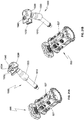
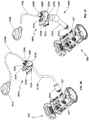
FIG. 6 is a exploded, perspective view of the spinal fixation device ofFIG. 1 with parts separated; -
FIG. 7 is a perspective view of the spinal fixation device ofFIG. 1 with a first end plate spaced apart from a body of the spinal fixation device; -
FIG. 8 is a rear view of the spinal fixation device ofFIG. 7 ; -
FIG. 9 is a cross-sectional view of the spinal fixation device ofFIG. 8 cut along section line "9-9" ofFIG. 8 ; -
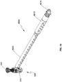
FIG. 10 is a perspective view of an insertion instrument illustrating use with the spinal fixation device ofFIG. 1 ; -
FIG. 11 is a top view of the insertion instrument ofFIG. 10 ; -
FIG. 12 is a perspective view of the insertion instrument ofFIG. 10 ; -
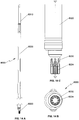
FIG. 13A is a side view of a height adjusting driver for use with the insertion instrument ofFIG. 10 ; -
FIG. 13B is a top view of the height adjusting driver ofFIG. 13A ; -
FIG. 13C is a partial side view of a distal portion of the height adjusting driver ofFIG. 13A ; -
FIG. 14A is a side view of an angle adjusting driver for use with the insertion instrument ofFIG. 10 ; -
FIG. 14B is a top view of the angle adjusting driver ofFIG. 14A ; -
FIG. 14C is a partial side view of a distal portion of the angle adjusting driver ofFIG. 14A ; -
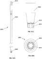
FIG. 15A is a side view of a tapered driver for use with the insertion instrument ofFIG. 10 ; -
FIG. 15B is a top view of the tapered driver ofFIG. 15A ; -
FIG. 15C is a partial side view of a distal portion of the tapered driver ofFIG. 15A ; -
FIG. 16 is a top view of the insertion instrument ofFIG. 10 illustrating use with the height adjusting driver ofFIG. 13A with the spinal fixation device ofFIG. 1 ; -
FIG. 17 is a cross-sectional view of the insertion instrument and the spinal fixation device ofFIG. 16 cut along section line "17-17" ofFIG. 16 ; -
FIG. 18 is a top view of the insertion instrument ofFIG. 10 illustrating use with the angle adjusting driver ofFIG. 14A and the spinal fixation device ofFIG. 1 ; and -
FIG. 19 is a cross-sectional view of the insertion instrument ofFIG. 18 cut along section line "19-19" ofFIG. 18 ; -
FIG. 20a is a perspective view of a rod connector for use with the spinal fixation device ofFIG. 1 ; -
FIG. 20b is a perspective view of the rod connector ofFIG. 20a illustrating polyaxial rotation thereof; -
FIG. 21a is a perspective view of the spinal fixation device ofFIG. 1 and the rod connector ofFIG. 20a ; -
FIG. 21b is a perspective view of the spinal fixation device and the rod connector ofFIG. 21a illustrating polyaxial rotation of the rod connector; -
FIG. 22 is a perspective view of the spinal fixation device and the rod connector ofFIG. 21a secured with the spinal fixation device illustrating use with a spinal rod; -
FIG. 23 is a perspective view of the spinal fixation device ofFIG. 22 secured between vertebral bodies by the rod connector and the spinal rod ofFIG. 22 ; -
FIG. 24 is a perspective view of the spinal fixation device ofFIG. 22 secured between the vertebral bodies by a pair of rod connectors and spinal rods ofFIG. 22 ; - IG. 25 is a perspective view of the spinal fixation device of
FIG. 1 and a drug delivery assembly operatively coupled with the spinal fixation device; -
FIG. 26 is a perspective view of the spinal fixation device ofFIG. 23 and a drug delivery assembly in accordance with another embodiment of the present disclosure; -
FIG. 27 is a perspective view of the spinal fixation device ofFIG. 1 and a drug delivery assembly for use with the spinal fixation device in accordance with another embodiment of the present disclosure; -
FIG. 28 is a perspective view of the spinal fixation device ofFIG. 1 and a drug delivery assembly for use with the spinal fixation device in accordance with an alternative embodiment of the present disclosure; and -
FIG. 29 is a perspective view of the spinal fixation device ofFIG. 23 and a shield for use with the spinal fixation device in accordance with an embodiment of the present disclosure, illustrating placement of the shield on the spinal fixation device in phantom. - Particular embodiments of the present disclosure will be described herein with reference to the accompanying drawings. As shown in the drawings and as described throughout the following description, and as is traditional when referring to relative positioning on an object, the terms "proximal" and "trailing" may be employed interchangeably, and should be understood as referring to the portion of a structure that is closer to a clinician during proper use. The terms "distal" and "leading" may also be employed interchangeably, and should be understood as referring to the portion of a structure that is farther from the clinician during proper use. In addition, the term "cephalad" or "cranial" is used in this application to indicate a direction toward a patient's head, whereas the term "caudad" indicates a direction toward the patient's feet. Further still, the term "medial" indicates a direction toward the middle of the body of the patient, whilst the term "lateral" indicates a direction toward a side of the body of the patient (i.e., away from the middle of the body of the patient). The term "posterior" indicates a direction toward the patient's back, and the term "anterior" indicates a direction toward the patient's front. In the following description, well-known functions or constructions are not described in detail to avoid obscuring the present disclosure in unnecessary detail.
- With reference to
FIGS. 1-4 and6 , an embodiment of the present disclosure is shown generally as aspinal fixation device 500 configured and adapted to be positioned between vertebral bodies to support vertebral bodies and to promote spinal fusion. By way of example,spinal fixation device 500 may be inserted into the patient laterally, posteriorly, anteriorly, or obliquely. Additionally,spinal fixation device 500 may be inserted into the patient through procedures such as, e.g., posterior lumbar interbody fusion (PLIF), transforaminal lumbar interbody fusion (TLIF), lateral lumbar interbody fusion (LLIF), oblique lumbar interbody fusion (OLIF), or lateral extracavitary (LECA) procedures.Spinal fixation device 500 includes anouter housing 510 and anend plate assembly 560 interchangeably coupled withouter housing 510.Outer housing 510 includes asecond end plate 550.End plate assembly 560 includes afirst end plate 540, first and secondelongate members first end plate 540, and a mountingassembly 600 operatively supporting first and secondelongate members second end plates second end plates second end plates spikes spinal fixation device 500 to the adjacent vertebral bodies for enhanced gripping of the vertebral bodies and minimizing movement ofspinal fixation device 500 relative to the vertebral bodies. However, it is also contemplated that each of first andsecond end plates spinal fixation device 500 to the vertebral bodies. -
End plate assembly 560 is configured as a modular assembly that is interchangeably mounted inouter housing 510. For example, a plurality ofend plate assemblies 560 may be provided with varying parameters such as, e.g., footprint and lordosis, such that the clinician may selectively attach a desiredend plate assembly 560 toouter housing 510 to meet the needs of each patient or surgical procedure being performed. In this manner,end plate assembly 560 may be tailored to achieve a desired lordosis of afirst end plate 540 and a desired axial spacing betweenouter housing 510 andfirst end plate 540, as will be discussed hereinbelow. -
Spinal fixation device 500 may be made of titanium, titanium alloy, stainless steel, allograft bone, autologous bone graft, polyetheretherketone (PEEK), cobalt chrome, polymeric materials, a combination thereof, or any other suitable biocompatible material. In particular,spinal fixation device 500 may be formed of bone, or an artificial material other than bone which may be harder or stronger than bone, such as, e.g., ceramic materials.Outer housing 510 may include a bone growth promoting material such as, e.g., bone morphogenic protein and hydroxyapatite.Outer housing 510 may define acavity 551 to accommodate bone graft material therein. - With reference to
FIGS. 5A, 5B , and6 ,outer housing 510 includes first and second ends 524, 526 and anouter wall 512 extending between first and second ends 524, 526.Outer wall 512 defines a plurality ofbores 521 configured to receive ascrew 190 and operatively engage insertion instrument 6000 (FIG. 10 ), as will be discussed hereinbelow.Bores 521 are circumferentially arranged aboutouter housing 510 to facilitate insertion ofscrew 190 and engagement withinsertion instrument 6000 at different orientations. In addition,outer wall 512 further defines a plurality of bores 527 (FIGS. 7 and 8 ) circumferentially arranged aboutouter housing 510 to facilitate fixation of spinal stabilization devices such as, e.g., a rod connector 1000 (FIGS. 20a and 20b ), or a drug delivery assembly 1700 (FIG. 25 ), as will be discussed hereinbelow. For example, the plurality ofbores 527 may be defined in anterolateral portions ofouter housing 510. - With particular reference to
FIGS. 6-9 ,first end 524 ofouter housing 510 defines anaperture 522, andsecond end 526 ofouter housing 510 includessecond end plate 550, e.g., integrally formed, withouter housing 510.Outer housing 510 defines achamber 520 configured to receive at least a portion ofend plate assembly 560 throughaperture 522.End plate assembly 560 is selectively positionable withinchamber 520.End plate assembly 560 includes a mountingassembly 600 releasably supported on ashoulder 530 offirst end 524 ofouter housing 510. Mountingassembly 600 includes a retaininghousing 602 including first andsecond housing halves rotatable members housing 602, and first and second retaining rings 606, 608. - With particular reference to
FIGS. 6 and7 ,aperture 522 offirst end 524 ofouter housing 510 includes a non-circular cross-section complementary to a transverse cross-section of afirst end 615 of retaininghousing 602 to inhibit rotation of retaininghousing 602 inaperture 522. In particular, each of first andsecond housing halves second protrusions second recesses shoulder 530 ofouter housing 510.Outer housing 510 defines a pair ofbores 571 transverse to a longitudinal axis "A" (FIG. 9 ) ofspinal fixation device 500. Eachbore 571 is configured to receive aspring pin 577. Each of first andsecond housing halves transverse groove 613 on respectivesecond protrusions 607.Transverse groove 613 is configured to receivespring pin 577. Under such a configuration,spring pin 577 inserted through therespective bore 571 ofouter housing 510 is received throughtransverse groove 613 of the respectivesecond protrusion 607 to secure retaininghousing 602 withouter housing 510.Spring pin 577 is flexible to enable the clinician to removeend plate assembly 560 fromouter body 510 whenend plate assembly 560 is pulled away fromouter housing 510. Whenend plate assembly 560 is pulled away fromouter housing 510,spring pin 577 flexes and disengages fromtransverse groove 613 ofsecond protrusion 607. In this manner, the clinician is able to interchangeably utilize variousend plate assemblies 560. - With continued reference to
FIG. 6 , each of first andsecond housing halves inner wall 611 defining first and secondcircumferential grooves rotatable member 610 defines acircumferential groove 670 configured to support first retainingring 606 therein. First retainingring 606 extends radially outward fromcircumferential groove 670 of firstrotatable member 610 such that at least a portion offirst retaining ring 606 is received in firstcircumferential groove 630 of retaininghousing 602. In this manner, firstrotatable member 610 is rotatably supported within retaininghousing 602. Similarly, secondrotatable member 612 defines acircumferential groove 672 configured to supportsecond retaining ring 608 therein.Second retaining ring 608 extends radially outward fromcircumferential groove 672 such that at least a portion ofsecond retaining ring 608 is received in secondcircumferential groove 632 of retaininghousing 602. In this manner, secondrotatable member 612 is rotatably supported within retaininghousing 602. Under such a configuration, first and secondrotatable members housing 602, while maintaining a fixed axial distance therebetween. - First and second
rotatable members internal threads 609, 613 (FIG. 6 ), respectively. In particular,internal threads rotatable members internal threads Internal threads outer threads elongate members end plate assembly 560, respectively. Under such a configuration, rotation of first and secondrotatable members elongate members FIG. 9 ), as will be described hereinbelow. In addition, first and secondrotatable members teeth Teeth portion 7030 of a height adjusting driver 7000 (FIG. 13A ), as will be discussed hereinbelow. Under such a configuration, rotation ofheight adjusting driver 7000 operatively coupled withteeth rotatable members elongate members - With continued reference to
FIGS. 7-9 ,end plate assembly 560 is selectively positionable relative toouter housing 510 through rotation of first and secondrotatable members spinal fixation device 500 may be selectively tailored to, e.g., the intervertebral space. - With particular reference now to
FIG. 9 ,first end plate 540 includes anunderside 545 defining first andsecond grooves second grooves round head portions elongate members Round head portions respective bores First end plate 540 further definesbores 541, 543 (FIG. 7 ) configured to receive respective pins 611 (FIG. 6 ). In this manner, pins 611 pivotably secureround head portions first end plate 540. Under such a configuration, relative axial movement of first and secondelongate members first end plate 540 with respect to longitudinal axis "A-A" (FIG. 9 ) to achieve the desired lordosis, as will be discussed hereinbelow. - First and second
elongate members end plate assembly 560 includeouter threads internal threads 609, 613 (FIG. 6 ) of first and secondrotatable members 602, 404. First and secondelongate members end plate assembly 560 are movable relative to each other along longitudinal axis "A-A". In this manner,first end plate 540 may be advantageously angled to provide a desired amount of lordosis tailored to the need of each patient. For example,first end plate 540 may be positioned substantially orthogonal to the longitudinal axis "A-A" (FIG. 9 ) and adjacentfirst end 524 ofouter housing 510. Alternatively,first end plate 540 may define an acute angle with longitudinal axis "A-A" (FIG. 9 ) and spaced apart fromfirst end 524. The clinician may useangle adjusting driver 8000 to adjust the relative positioning of first and secondelongate members first end plate 540, as will be described hereinbelow. - With reference now to
FIGS. 10-12 , there is shown aninsertion instrument 6000 for use withspinal fixation device 500 to positionspinal fixation device 500 between adjacent vertebral bodies.Insertion instrument 6000 includes ahandle 6010 and anelongate body 6020 extending fromhandle 6010.Insertion instrument 6000 defines a channel 6035 (FIG. 17 ) configured to receive a height adjusting driver 7000 (a distal end of height adjusting driver 700 shown inFIG. 17 ), an angle adjusting driver 8000 (FIG. 18 ), or a tapered driver 9000 (FIGS. 15A-C ) therethrough.Elongate body 6020 includes engaging portion 6032 (FIG. 17 ) configured to, e.g., threadably, engage bore 521 ofouter housing 510 to securely attachspinal fixation device 500 withinsertion instrument 6000. - With reference now to
FIGS. 13A-C andFIG. 17 , there is provided aheight adjusting driver 7000 configured to be received through channel 6035 (FIG. 17 ) ofinsertion instrument 6000.Height adjusting driver 7000 includes ahandle 7010, anelongate body 7020, and an engagingportion 7030. Engagingportion 7030 includes a plurality ofteeth 7032 configured to engageteeth 684, 682 (FIG. 6 ) of first and secondrotatable members assembly 600, respectively. In this manner, rotation ofhandle 7010 causes concomitant rotation of engagingportion 7030 aboutelongate body 7020, which, in turn, causes rotation of first and secondrotatable members rotatable members elongate members first end plate 540 andouter housing 510, i.e., overall height ofspinal fixation device 500. Rotation ofhandle 7010 in an opposite direction causes axial movement ofend plate assembly 560 in an opposite direction. - With reference now to
FIGS. 14A-C and19 , there is provided anangle adjusting driver 8000 configured to be received through channel 6035 (FIG. 17 ) ofinsertion instrument 6000.Angle adjusting driver 8000 includes ahandle 8010, anelongate body 8020, and an engagingportion 8030. For example, engagingportion 8030 may be radially offset from a central axis "C-C" defined byelongate body 8020. Engagingportion 8030 includes a plurality ofteeth 8034 configured to engageteeth 682, 684 (FIG. 6 ) of either first or secondrotatable members assembly 600. In this manner, rotation ofhandle 8010 causes rotation of one of the first or secondrotatable members assembly 600. Rotation of only onerotatable member elongate member elongate members first end plate 540 with respect toouter housing 510 and longitudinal axis "A-A." In this manner, the clinician may adjust the angular orientation offirst end plate 540 to achieve the desired amount of lordosis or kyphosis. It is also contemplated thatheight adjusting driver 7000 andangle adjusting driver 8000 may be constructed as a single instrument that is configured to be received through channel 6035 (FIG. 17 ) ofinsertion instrument 6000. - With reference now to
FIGS. 15A-C , there is provided a tapereddriver 9000 configured to be received through channel 6035 (FIG. 17 ) ofinsertion instrument 6000.Tapered driver 9000 includes ahandle 9010, anelongate body 9020, and an engagingportion 9030. Upon achieving the desired height ofspinal fixation device 500 usingheight adjusting driver 7000 and angular orientation offirst end plate 540 usingangle adjusting driver 8000, screws 190 may be positioned inbore 521 ofouter housing 510 throughchannel 6035 ofinsertion instrument 6000.Teeth 9034 of engagingportion 9030 engage teeth on a head portion ofscrew 190. Under such a configuration, handle 9010 may be rotated to threadablysecure screw 190 inbore 521. - With reference now to
FIGS. 20-21 , arod connector 1000 and a spinal rod 1500 (FIG. 22 ) may be used withspinal fixation device 500 to enhance securement ofspinal fixation device 500 between vertebral bodies and to promote spinal fusion.Rod connector 1000 includes ananchoring portion 1010, acoupling portion 1020 rotatably and pivotably coupled with anchoringportion 1010, and ahead portion 1030. Anchoringportion 1010 includes an engagingportion 1012 configured to be threadably coupled with bore 527 (FIGS. 21a and 21b ) ofspinal fixation device 500. Anchoringportion 1010 further includes atip portion 1014 extending from engagingportion 1012.Tip portion 1014 has a diameter smaller than a diameter of engagingportion 1012 to facilitate alignment of engagingportion 1012 withbore 527. Anchoringportion 1010 further includes a ball joint 1016 (FIG. 20b ).Coupling portion 1020 includes asocket 1022 configured to rotatably and pivotably receive ball joint 1016 of anchoringportion 1010. Under such a configuration, variable or polyaxial adjustments may be made between anchoringportion 1010 andcoupling portion 1020. It is also contemplated that anchoringportion 1010 may include a socket andcoupling portion 1020 may include a ball joint. - With reference to
FIGS. 20-22 ,coupling portion 1020 is secured withhead portion 1030.Head portion 1030 includes a recessedportion 1032 configured to receivespinal rod 1500 therethrough.Head portion 1030 definesslits 1038 configured to flex or enlarge the dimensions of recessedportion 1032 to facilitate insertion ofspinal rod 1500.Head portion 1030 further defines a bore 1034 (FIG. 21a ) configured to receive ascrew 1040. Upon insertion ofspinal rod 1500 in recessedportion 1032,screw 1040 may be fastened to securespinal rod 1500 in recessedportion 1032. With particular reference toFIG. 22 ,spinal rod 1500 may be, e.g., a 5.5 mm diameter round rod. A reference may be made toU.S. Patent Application Serial No. 13/251,546 , nowU.S. Patent No. 8,920,471, filed on October 3, 2011 , entitled "Transverse Connector," for a detailed discussion of the construction and operation of screws. - With reference now to
FIG. 23 , it is also envisioned thatspinal fixation device 500 may be tailored to a particular surgical procedure being performed. For example, spinal fixation device 500' may include a plurality of bores 527' axially arranged along a length of spinal fixation device 500'. Under such a configuration,rod connector 1000 may be secured at a desired location along the length ofspinal fixation device 500 to better secure spinal fixation device 500' between vertebral bodies v1, v2. In addition, it is also contemplated thatadditional rod connectors 1000 may be axially placed along the length of spinal fixation device 500' to further secure spinal fixation device 500'. In this manner, after spinal fixation device 500' is positioned between vertebral bodies v1, v2,pedicle screws 1600 may be secured to respective vertebral bodies v1, v2 and at least onerod connector 1000 may be secured with spinal fixation device 500'.Spinal rod 1500 may be received through the pedicle screws androd connector 1000.Screw 1040 is utilized to securespinal rod 1500 in recessedportion 1032 ofrod connector 1000 and set screws (not shown) are used to securespinal rod 1500 withpedicle screws 1600. A reference may be made toU.S. Patent Application Serial Nos. 12/739,461 , nowU.S. Patent No. 8,814,919, filed on August 26, 2014 , entitled "Posterior Pedicle Screw Having a Taper Lock," and12/739,506, filed on October 22, 2008 - With reference to
FIG. 24 , it is also envisioned that a pair ofspinal rods 1500 may be utilized to further secure spinal fixation device 500' between vertebral bodies v1, v2. As discussed hereinabove,additional rod connectors 1000 may be axially placed along the length of spinal fixation device 500'. - With reference now to
FIG. 25 , bores 527 may also be used to secure adrug delivery assembly 1700 to deliver a range of different synthetic or naturally occurring pharmaceutical or biological agents in liquid or gel formulations depending upon the particular application. Drugs may be administered for any actual or potential therapeutic, prophylactic or other medicinal purpose. Such drugs may include, e.g., analgesics, anesthetics, antimicrobial agents, antibodies, anticoagulants, antifibrinolytic agents, anti-inflammatory agents, antiparasitic agents, antiviral agents, cytokines, cytotoxins or cell proliferation inhibiting agents, chemotherapeutic agents, radiolabeled compounds or biologies, hormones, interferons, and combinations thereof. Thus, it is contemplated thatspinal fixation device 500 may be used to deliver a formulation comprising an agent used in chemotherapy or radiotherapy. - Therapeutic agents may include chemotherapeutic agents (for example, paclitaxel, vincristine, ifosfamide, dacttinomycin, doxorubicin, cyclophosphamide, and the like), bisphosphonates (for example, alendronate, pamidronate, clodronate, zoledronic acid, and ibandronic acid), analgesics (such as opioids and NSAIDS), anesthetics (for example, ketoamine, bupivacaine and ropivacaine), tramadol, and dexamethasone. In other variations,
drug delivery assembly 1700 may be used for delivering an agent useful in radiotherapy in, e.g., beads. - As an alternative to systemic administration of radioactive agents that are capable of targeting a particular tissue, antigen, or receptor type, the radioactive agents are administered locally following implantation of
spinal fixation device 500. Such radiotherapy agents include radiolabeled antibodies, radiolabeled peptide receptor ligands, or any other radiolabeled compound capable of specifically binding to the specific targeted cancer cells. - In addition,
drug delivery assembly 1700 may be used to deliver drugs used in the management of pain and swelling that occurs following the implantation surgery. For example,spinal fixation device 500 may release an effective amount of an analgesic agent alone or in combination with an anesthetic agent. As yet another alternative,spinal fixation device 500 may be used to deliver drugs which help minimize the risk of infection following implantation. For example,spinal fixation device 500 may release one or more antibiotics (for example, cefazolin, cephalosporin, tobramycin, gentamycin, etc.) and/or another agent effective in preventing or mitigating biofilms (for example, a quorum-sensing blocker or other agent targeting biofilm integrity). Bacteria may form biofilms on the surface ofspinal fixation device 500, and these biofilms may be relatively impermeable to antibiotics. Accordingly, systemically administered antibiotics may not achieve optimal dosing where it is most needed. However,spinal fixation device 500 enables the delivery of the desired dose of antibiotic precisely when and where needed. In certain circumstances, the antibiotic may be delivered beneath the biofilm. - With reference to
FIG. 25 ,drug delivery assembly 1700 includes adrug reservoir 1720 secured withbore 527, acatheter 1730 in fluid communication withdrug reservoir 1720, and asupply port 1740 in fluid communication withcatheter 1730.Supply port 1740 may be affixed to a location most convenient for the patient or the clinician to supply the drugs using, e.g.,syringe 1750. For example,supply port 1740 may be affixed to an external location such as, e.g., the skin, of the patient.Supply port 1740 shown herein is merely exemplary and not drawn to scale.Supply port 1740 having different sizes, shapes, or profiles may be utilized for other applications such as, e.g., subcutaneous application. - The drugs discussed hereinabove, may be supplied through
supply port 1740 by asyringe 1750. It is also contemplated thatdrug reservoir 1720 may be preloaded with a predetermined amount of drugs to eliminatecatheter 1730,supply port 1740, andsyringe 1750. It is further contemplated thatspinal fixation device 500 may include channels, pores, and/or passages (not shown) formed in, e.g.,outer housing 510. The channels, pores, and/or passages may be in fluid communication withdrug reservoir 1720 to facilitate delivery of the drugs fromdrug reservoir 1720 to the delivery target. - With reference to
FIG. 26 , bores 527' of spinal fixation device 500' or alternatively, bores 527 ofspinal fixation device 500, may also be used to secure adrug delivery assembly 1800 to deliver the drugs.Drug delivery assembly 1800 includes acannula 1810 defining achannel 1820 therethrough. The drugs discussed hereinabove, may be supplied tobores 527, 527' bysyringe 1750 coupled tocannula 1810. It is contemplated thatcannula 1810 may be coupled tospinal fixation device 500, 500' to supply the drugs to the delivery target during the surgical procedure and may be removed after the completion of the surgical procedure. - With reference now to
FIG. 27 , it is also envisioned that adrug delivery assembly 1900 may be utilized to deliver the drugs to the delivery target.Drug delivery assembly 1900 includesrod connector 2000, aseal member 2060, asupply port 1940, and acatheter 1930 interconnectingsupply port 1940 androd connector 2000. In particular,rod connector 2000 defines a channel (not shown) extending therethrough such that whenrod connector 2000 is coupled withspinal fixation device 500, 500', the channel is in fluid communication withbore 527, 527' ofspinal fixation device 500, 500' to facilitate drug delivery throughrod connector 2000. -
Rod connector 2000 has a substantially similar configuration asrod connector 1000. The portions ofrod connector 2000 that are identical torod connector 1000, as discussed hereinabove, will not be discussed in detail.Rod connector 2000 includes ananchoring portion 2010, acoupling portion 2020 rotatably and pivotably coupled with anchoringportion 2010, and ahead portion 2030. Anchoringportion 2010 includes an engagingportion 2012 configured to be threadably coupled withbore 527 ofspinal fixation device 500.Coupling portion 2020 is secured withhead portion 2030.Head portion 2030 includes a recessedportion 2032 configured to receivespinal rod 1500 therethrough.Head portion 2030 definesslits 2038 configured to flex or enlarge the dimensions of recessedportion 2032 to facilitate insertion ofspinal rod 1500.Head portion 1030 further defines abore 2034 configured to receivescrew 1040. Upon insertion ofspinal rod 1500 in recessedportion 2032,screw 1040 may be fastened to securespinal rod 1500 in recessedportion 2032. Furthermore,head portion 2030 defines abore 2050 in communication with the channel.Bore 2050 is dimensioned to receiveseal member 2060 in a sealing relation. Under such a configuration, when the patient or the clinician supplies the drugs throughsupply port 1940 using, e.g., syringe 1750 (FIG. 25 ), the drugs flow through the channel ofrod connector 2000 and to the drug delivery target throughbore 527, 527' ofspinal fixation device 500, 500'. Alternatively,rod connector 2000 may include a drug reservoir preloaded with a predetermined amount of drugs such thatcatheter 1930,supply port 1940, andseal member 2060 may be eliminated. Under such a configuration, a plug may be used to closebore 2050 in communication with the channel. In this manner,rod connector 2000 may provide, e.g., time-release, drug delivery. - With reference now to
FIG. 28 , it is also envisioned that adrug delivery assembly 3000 may be utilized to deliver the drugs to the delivery target. In particular,drug delivery assembly 3000 includes arod connector 3010, an engagingportion 3012, aseal member 3060, asupply port 3014, andcatheters Rod connector 3010 is substantially identical tohead portion 2030 ofdrug delivery assembly 1900, and thus, will not be described in detail herein.Rod connector 3010 includes a recessedportion 3032 configured to receivespinal rod 1500 therethrough.Rod connector 3010 definesslits 3038 configured to flex or enlarge the dimensions of recessedportion 3032 to facilitate insertion ofspinal rod 1500.Rod connector 3010 further defines abore 3034 configured to receivescrew 1040. Upon insertion ofspinal rod 1500 in recessedportion 3032,screw 1040 may be fastened to securespinal rod 1500 in recessedportion 3032. Furthermore, connectingrod 3010 defines abore 3050.Bore 3050 is dimensioned to receiveseal member 3060 in a sealing relation.Catheter 3016a connects bore 3050 with engagingportion 3012, andcatheter 3016b interconnectssupply port 3014 withseal member 3060. Engagingportion 3012 may be e.g., threadably, coupled withbore 527, 527' ofspinal fixation device 500, 500'. Under such a configuration, when the patient or the clinician supplies the drugs to supplyport 3014 using, e.g., syringe 1750 (FIG. 25 ), the drugs flow throughrod connector 3010 and bores 527, 527' ofspinal fixation device 500, 500' to the drug delivery target. Alternatively,rod connector 3010 may include a drug reservoir preloaded with a predetermined amount of drugs such thatcatheter 3016b,supply port 3014, andseal member 3060 are eliminated. Under such a configuration, a plug (not shown) may be used to closebore 3050. In this manner,rod connector 3010 may provide, e.g., time-release, drug delivery. - With reference to
FIG. 29 , a shield for use withspinal fixation device 500, 500' is generally shown as 4000.Shield 4000 may be affixed tospinal fixation device 500, 500' using adhesive, ultrasonic welding or other suitable means.Shield 4000 may include, e.g., polyphenylene sulfide (PPS), to reduce radiation to the spinal cord during, e.g., post-operative radiotherapy. In addition,shield 4000 may serve as a barrier for bone cement such as, e.g., polymethyl methacrylate (PMMA), drugs, or bone graft products and biologics. In addition,shield 4000 may include, e.g., slow release agents such as antibiotics. - In use, the clinician first distracts vertebral bodies of interest to establish the intervertebral space. The clinician may then remove vertebral tissue, if necessary or desired. First and second
elongate members end plate assembly 560 are selectively positioned to achieve a desired orientation offirst end plate 540.Insertion instrument 6000 is coupled withspinal fixation device 500 by, e.g., threadably, coupling engaging portion 6032 (FIG. 17 ) withbore 521.Spinal fixation device 500 is then positioned adjacent a desired intervertebral space between vertebral bodies. Upon insertingspinal fixation device 500 in the intervertebral space,height adjusting driver 7000 can be inserted through channel 6035 (FIGS. 16 and 17 ) ofinsertion instrument 6000 to further adjust the axial distance betweenfirst end plate 560 andouter housing 510 by placing engagingportion 7030 through one of the plurality ofbores 521 defined inouter housing 510 such thatteeth 7032 of engagingportion 7030 ofheight adjusting driver 7000 engagesteeth rotatable members assembly 600, respectively. In this manner, rotation ofhandle 7010 causes rotation of first and secondrotatable members elongate members first end plate 540 andouter housing 510, i.e., height ofspinal fixation device 500.Handle 7010 is rotated until a desired height ofspinal fixation device 500 is effected through axial movement ofend plate assembly 560. - In addition, after removing
height adjusting driver 7000 frominsertion instrument 6000,angle adjusting driver 8000 can be inserted through channel 6035 (FIG. 19 ) ofinsertion instrument 6000 to further adjust the angular orientation offirst end plate 540 with respect toouter housing 510. Engagingportion 8030 is inserted through one of the plurality ofbores 521 defined inouter housing 510 such thatteeth 8034 of engagingportion 8030 ofangle adjusting driver 8000 engagesteeth 682 of firstrotatable member 610 orteeth 684 of secondrotatable member 612 of mountingassembly 600. Rotation ofhandle 8010 causes rotation of one of the first or secondrotatable members assembly 600, which, in turn, causes translation of one of first or secondelongate members elongate members first end plate 540 with respect toouter housing 510 to achieve the desired lordosis or kyphosis. It is contemplated that the clinician may make further adjustments by alternatingheight adjusting driver 7000 andangle adjusting driver 8000 to achieve the desired length ofspinal fixation device 500 and angular orientation offirst end plate 540. Upon achieving the desired length ofspinal fixation device 500 and angular orientation offirst end plate 540, screw 190 may be placed inbore 521 defined inouter housing 510 throughchannel 6035 ofinsertion instrument 6000.Screw 190 may be threadably secured inbore 521 by using tapereddriver 9000. - At this time,
rod connector 1000,pedicle screws 1600, andspinal rod 1500 may be utilized to further securespinal fixation device 500 between vertebral bodies and to further promote spinal fusion. Anchoringportion 1010 ofrod connector 1000 is threadably coupled withbore 527 ofspinal fixation device 500, andpedicle screws 1600 are secured with respective vertebral bodies. Thereafter,spinal rod 1500 is inserted through recessedportion 1032 ofrod connector 1000 and respective pedicle screws 1600. At this time,rod connector 1000 may be adjusted for proper angular orientation.Screw 1040 may be used to securespinal rod 1500 in recessedportion 1032 ofrod connector 1000 and the set screws (not shown) may be used to securespinal rod 1500 withpedicle screws 1600. At this time,additional rod connector 1000 may be used to further securespinal fixation device 500 between vertebral bodies. At this time, additionalspinal rod 1500 may be utilized to further secure spinal fixation device 500 (FIG. 24 ). - Based on the needs of the patient,
drug delivery assemblies drug reservoir 1720 ofdrug delivery assembly 1700 is secured withbore 527 ofspinal fixation device 500.Supply port 1740 may be affixed to a location most convenient for the patient or the clinician to supply the drugs using, e.g.,syringe 1750. Alternatively,cannula 1810 ofdrug delivery assembly 1800 is secured withbore 527 ofspinal fixation device 500. The patient or the clinician may administer thedrugs using syringe 1750. The use ofdrug delivery assemblies drug delivery assemblies catheter 1730 to supply the drugs.
Claims (12)
- A spinal fixation device (500) comprising:an outer housing (510) defining an aperture (522) and a longitudinal axis; andan end plate assembly (560) coupled with the outer housing, at least a portion of the end plate assembly slidably received within the outer housing (510) through said aperture of the outer housing, (510), the end plate assembly (560) including a first end plate (540) configured to engage a vertebral body, wherein the end plate assembly (560) is selectively movable between a first position in which the first end plate (540) is spaced apart from the outer housing (510) and a second position in which the first end plate (540) is adjacent the outer housing (510), and the first end plate (540) is selectively adjustable to an angular orientation of a plurality of angular orientations with respect to the longitudinal axis of the outer housing (510),wherein the end plate assembly (560) includes first and second elongate members (666, 668) operatively coupled to the first end plate (540) such that axial movement of the first and second elongate members (666, 668) in tandem causes axial displacement of the first end plate (540), and relative movement between the first and second elongate members (666, 668) transitions the first end plate (540) from a first angular orientation to a second angular orientation, and wherein the spinal fixation device further comprises a mounting assembly (600) operatively supporting the first and second elongate members (666, 668) in the outer housing (510),characterized in that the mounting assembly (600) includes a retaining housing (602) and first and second rotatable members (610, 612) rotatably supported in the retaining housing (602), the first and second rotatable members (610, 612) operatively coupled with the first and second elongate members (666, 668) of the end plate assembly (560) respectively.
- The spinal fixation device according to claim 1, wherein the mounting assembly (600) is releasably secured with the outer housing (510).
- The spinal fixation device according to claim 1 or 2, wherein the first and second rotatable members (610, 612) of the mounting assembly (600) are spaced apart from each other to define a gap therebetween.
- The spinal fixation device according to claim 1, 2 or 3, wherein each of the first and second rotatable members (610, 612) of the mounting assembly (600) includes circumferentially arranged teeth opposing each other.
- The spinal fixation device according to any preceding claim, wherein the first rotatable member (610) of the mounting assembly (600) includes inner threads in a first orientation and the second rotatable member (612) of the mounting assembly (600) includes inner threads in a second orientation opposite to the first orientation.
- The spinal fixation device according to claim 3, 4 or 5, wherein the outer housing (510) defines a plurality of bores, at least one bore of the plurality of bores in communication with the gap defined between the first and second rotatable members (610, 612) of the mounting assembly (600).
- The spinal fixation device according to claim 6, wherein the plurality of bores are circumferentially arranged about the outer housing (510), or
wherein the plurality of bores are arranged along a length of the outer housing (510). - A kit for spinal surgery comprising:a spinal fixation device (500) according to any preceding claim; anda surgical instrument defining a channel extending therethrough, the surgical instrument defining an engaging portion configured to securely engage the outer housing of the spinal fixation device.
- The kit for spinal surgery according to claim 8 when dependent on claim 4, wherein the surgical instrument includes a height adjusting driver (7000) rotatably extending through the channel of the surgical instrument, the height adjusting driver (7000) including an engaging portion having teeth configured to engage the circumferentially arranged teeth of the first and second rotatable members (610, 612) of the mounting assembly (600), whereby rotation of the height adjusting driver (7000) causes rotation of the first and second rotatable members (610, 612) of the mounting assembly (600), and/or
wherein the surgical instrument further includes an angle adjusting driver (8000) rotatably extending through the channel of the surgical instrument, the angle adjusting driver (8000) including an engaging portion having teeth configured to engage the circumferentially arranged teeth of one of the first or second rotatable members (610, 612) of the mounting assembly (600), whereby rotation of the angle adjusting driver (8000) causes rotation of the one of the first or second rotatable members (610, 612) of the mounting assembly (600). - The kit for spinal surgery according to claim 8 or 9, comprising a rod connector (1000) in addition to or instead of the surgical instrument, the rod connector (1000) having an anchoring portion coupled with the outer housing of the spinal fixation device (500) and a head portion having a recessed portion configured to receive a spinal rod, preferably
wherein the rod connector (1000) defines a channel therethrough, more preferably
wherein the head portion of the rod connector (1000) defines a bore in communication with the channel. - The kit for spinal surgery according to claim 8, 9 or 10, further comprising a drug delivery assembly in addition to or instead of the surgical instrument, the drug delivery assembly including a drug reservoir securely coupled with the outer housing (510) of the spinal fixation device (500), a supply port, and a catheter in fluid communication with the supply port and the drug reservoir.
- The kit for spinal surgery according to claim 8, 9, 10 or 11, further comprising a shield (4000) in addition to or instead of the surgical instrument, the shield attachable to the spinal fixation device (500), preferably
wherein the shield (4000) is configured to reduce radiation to a spinal cord, more preferably
wherein the shield (4000) includes slow releasing medicament.
Applications Claiming Priority (1)
| Application Number | Priority Date | Filing Date | Title |
|---|---|---|---|
| US201462078666P | 2014-11-12 | 2014-11-12 |
Publications (2)
| Publication Number | Publication Date |
|---|---|
| EP3020375A1 EP3020375A1 (en) | 2016-05-18 |
| EP3020375B1 true EP3020375B1 (en) | 2019-01-09 |
Family
ID=54540963
Family Applications (1)
| Application Number | Title | Priority Date | Filing Date |
|---|---|---|---|
| EP15194277.8A Active EP3020375B1 (en) | 2014-11-12 | 2015-11-12 | Spinal fixation device |
Country Status (2)
| Country | Link |
|---|---|
| EP (1) | EP3020375B1 (en) |
| AU (1) | AU2015255166B2 (en) |
Families Citing this family (2)
| Publication number | Priority date | Publication date | Assignee | Title |
|---|---|---|---|---|
| EP3349695B1 (en) * | 2015-09-18 | 2020-11-18 | K2M, Inc. | Corpectomy device |
| CN115778646B (en) * | 2022-11-16 | 2023-05-16 | 北京纳通医疗科技控股有限公司 | Vertebral body fixation system |
Family Cites Families (5)
| Publication number | Priority date | Publication date | Assignee | Title |
|---|---|---|---|---|
| ES2390567T3 (en) * | 2006-07-14 | 2012-11-14 | Biedermann Technologies Gmbh & Co. Kg | Separator for insertion between two vertebrae |
| JP5651472B2 (en) | 2007-10-23 | 2015-01-14 | ケー2エム, インコーポレイテッド | Posterior pedicle screw with taper lock |
| US8920471B2 (en) | 2010-07-12 | 2014-12-30 | K2M, Inc. | Transverse connector |
| US8377140B2 (en) * | 2011-01-12 | 2013-02-19 | Ebi, Llc | Expandable spinal implant device |
| US9707096B2 (en) * | 2013-03-14 | 2017-07-18 | K2M, Inc. | Spinal fixation device |
-
2015
- 2015-11-09 AU AU2015255166A patent/AU2015255166B2/en active Active
- 2015-11-12 EP EP15194277.8A patent/EP3020375B1/en active Active
Non-Patent Citations (1)
| Title |
|---|
| None * |
Also Published As
| Publication number | Publication date |
|---|---|
| EP3020375A1 (en) | 2016-05-18 |
| AU2015255166A1 (en) | 2016-06-09 |
| AU2015255166B2 (en) | 2020-09-10 |
Similar Documents
| Publication | Publication Date | Title |
|---|---|---|
| US12220325B2 (en) | Spinal fixation device | |
| US9044284B2 (en) | Intervertebral insert system | |
| CN108852562B (en) | Expanded interbody implant and articulating inserter and methods of use | |
| US10226356B2 (en) | Universally expanding cage | |
| AU2021201171B2 (en) | Corpectomy device and method of use thereof | |
| CN108498151B (en) | Expanded interbody implant and articulating inserter and methods of use | |
| US8496706B2 (en) | Bone cage with components for controlled expansion | |
| US10369004B2 (en) | Expandable intervertebralspacer | |
| US9707096B2 (en) | Spinal fixation device | |
| US7588599B2 (en) | Interbody cage system | |
| US20150045892A1 (en) | Interbody implants and graft delivery systems | |
| US20100222750A1 (en) | Replenishable drug delivery implant for bone and cartilage | |
| CN105188582A (en) | Adaptable interbody implant and methods of use | |
| EP3758634A1 (en) | Spinal implants with custom density and 3-d printing of spinal implants | |
| AU2011305680B2 (en) | Fusion cage with combined biological delivery system | |
| AU2015255166B2 (en) | Spinal fixation device | |
| JP2021535780A (en) | Spinal implant system and method |
Legal Events
| Date | Code | Title | Description |
|---|---|---|---|
| PUAI | Public reference made under article 153(3) epc to a published international application that has entered the european phase |
Free format text: ORIGINAL CODE: 0009012 |
|
| AK | Designated contracting states |
Kind code of ref document: A1 Designated state(s): AL AT BE BG CH CY CZ DE DK EE ES FI FR GB GR HR HU IE IS IT LI LT LU LV MC MK MT NL NO PL PT RO RS SE SI SK SM TR |
|
| AX | Request for extension of the european patent |
Extension state: BA ME |
|
| RIN1 | Information on inventor provided before grant (corrected) |
Inventor name: BOYD, CLINT Inventor name: MENDEL, EHUD Inventor name: JONES, SCOTT Inventor name: WALLENSTEIN, TODD Inventor name: BUCHOWSKI, JACOB M. Inventor name: SUTTERLIN, III, CHESTER E. Inventor name: FINN, MICHAEL |
|
| STAA | Information on the status of an ep patent application or granted ep patent |
Free format text: STATUS: REQUEST FOR EXAMINATION WAS MADE |
|
| 17P | Request for examination filed |
Effective date: 20161111 |
|
| RBV | Designated contracting states (corrected) |
Designated state(s): AL AT BE BG CH CY CZ DE DK EE ES FI FR GB GR HR HU IE IS IT LI LT LU LV MC MK MT NL NO PL PT RO RS SE SI SK SM TR |
|
| STAA | Information on the status of an ep patent application or granted ep patent |
Free format text: STATUS: EXAMINATION IS IN PROGRESS |
|
| 17Q | First examination report despatched |
Effective date: 20170223 |
|
| GRAP | Despatch of communication of intention to grant a patent |
Free format text: ORIGINAL CODE: EPIDOSNIGR1 |
|
| STAA | Information on the status of an ep patent application or granted ep patent |
Free format text: STATUS: GRANT OF PATENT IS INTENDED |
|
| INTG | Intention to grant announced |
Effective date: 20180910 |
|
| RIN1 | Information on inventor provided before grant (corrected) |
Inventor name: FINN, MICHAEL Inventor name: BUCHOWSKI, JACOB M. Inventor name: MENDEL, EHUD Inventor name: JONES, SCOTT Inventor name: WALLENSTEIN, TODD Inventor name: BOYD, CLINT Inventor name: SUTTERLIN, III CHESTER E. |
|
| GRAS | Grant fee paid |
Free format text: ORIGINAL CODE: EPIDOSNIGR3 |
|
| RAP1 | Party data changed (applicant data changed or rights of an application transferred) |
Owner name: K2M, INC. |
|
| GRAA | (expected) grant |
Free format text: ORIGINAL CODE: 0009210 |
|
| STAA | Information on the status of an ep patent application or granted ep patent |
Free format text: STATUS: THE PATENT HAS BEEN GRANTED |
|
| AK | Designated contracting states |
Kind code of ref document: B1 Designated state(s): AL AT BE BG CH CY CZ DE DK EE ES FI FR GB GR HR HU IE IS IT LI LT LU LV MC MK MT NL NO PL PT RO RS SE SI SK SM TR |
|
| REG | Reference to a national code |
Ref country code: GB Ref legal event code: FG4D |
|
| REG | Reference to a national code |
Ref country code: CH Ref legal event code: EP Ref country code: AT Ref legal event code: REF Ref document number: 1086393 Country of ref document: AT Kind code of ref document: T Effective date: 20190115 |
|
| REG | Reference to a national code |
Ref country code: DE Ref legal event code: R096 Ref document number: 602015023115 Country of ref document: DE |
|
| REG | Reference to a national code |
Ref country code: IE Ref legal event code: FG4D |
|
| REG | Reference to a national code |
Ref country code: NL Ref legal event code: MP Effective date: 20190109 |
|
| REG | Reference to a national code |
Ref country code: LT Ref legal event code: MG4D |
|
| PG25 | Lapsed in a contracting state [announced via postgrant information from national office to epo] |
Ref country code: NL Free format text: LAPSE BECAUSE OF FAILURE TO SUBMIT A TRANSLATION OF THE DESCRIPTION OR TO PAY THE FEE WITHIN THE PRESCRIBED TIME-LIMIT Effective date: 20190109 |
|
| REG | Reference to a national code |
Ref country code: AT Ref legal event code: MK05 Ref document number: 1086393 Country of ref document: AT Kind code of ref document: T Effective date: 20190109 |
|
| PG25 | Lapsed in a contracting state [announced via postgrant information from national office to epo] |
Ref country code: FI Free format text: LAPSE BECAUSE OF FAILURE TO SUBMIT A TRANSLATION OF THE DESCRIPTION OR TO PAY THE FEE WITHIN THE PRESCRIBED TIME-LIMIT Effective date: 20190109 Ref country code: PL Free format text: LAPSE BECAUSE OF FAILURE TO SUBMIT A TRANSLATION OF THE DESCRIPTION OR TO PAY THE FEE WITHIN THE PRESCRIBED TIME-LIMIT Effective date: 20190109 Ref country code: PT Free format text: LAPSE BECAUSE OF FAILURE TO SUBMIT A TRANSLATION OF THE DESCRIPTION OR TO PAY THE FEE WITHIN THE PRESCRIBED TIME-LIMIT Effective date: 20190509 Ref country code: NO Free format text: LAPSE BECAUSE OF FAILURE TO SUBMIT A TRANSLATION OF THE DESCRIPTION OR TO PAY THE FEE WITHIN THE PRESCRIBED TIME-LIMIT Effective date: 20190409 Ref country code: SE Free format text: LAPSE BECAUSE OF FAILURE TO SUBMIT A TRANSLATION OF THE DESCRIPTION OR TO PAY THE FEE WITHIN THE PRESCRIBED TIME-LIMIT Effective date: 20190109 Ref country code: LT Free format text: LAPSE BECAUSE OF FAILURE TO SUBMIT A TRANSLATION OF THE DESCRIPTION OR TO PAY THE FEE WITHIN THE PRESCRIBED TIME-LIMIT Effective date: 20190109 Ref country code: ES Free format text: LAPSE BECAUSE OF FAILURE TO SUBMIT A TRANSLATION OF THE DESCRIPTION OR TO PAY THE FEE WITHIN THE PRESCRIBED TIME-LIMIT Effective date: 20190109 |
|
| PG25 | Lapsed in a contracting state [announced via postgrant information from national office to epo] |
Ref country code: HR Free format text: LAPSE BECAUSE OF FAILURE TO SUBMIT A TRANSLATION OF THE DESCRIPTION OR TO PAY THE FEE WITHIN THE PRESCRIBED TIME-LIMIT Effective date: 20190109 Ref country code: RS Free format text: LAPSE BECAUSE OF FAILURE TO SUBMIT A TRANSLATION OF THE DESCRIPTION OR TO PAY THE FEE WITHIN THE PRESCRIBED TIME-LIMIT Effective date: 20190109 Ref country code: GR Free format text: LAPSE BECAUSE OF FAILURE TO SUBMIT A TRANSLATION OF THE DESCRIPTION OR TO PAY THE FEE WITHIN THE PRESCRIBED TIME-LIMIT Effective date: 20190410 Ref country code: IS Free format text: LAPSE BECAUSE OF FAILURE TO SUBMIT A TRANSLATION OF THE DESCRIPTION OR TO PAY THE FEE WITHIN THE PRESCRIBED TIME-LIMIT Effective date: 20190509 Ref country code: BG Free format text: LAPSE BECAUSE OF FAILURE TO SUBMIT A TRANSLATION OF THE DESCRIPTION OR TO PAY THE FEE WITHIN THE PRESCRIBED TIME-LIMIT Effective date: 20190409 Ref country code: LV Free format text: LAPSE BECAUSE OF FAILURE TO SUBMIT A TRANSLATION OF THE DESCRIPTION OR TO PAY THE FEE WITHIN THE PRESCRIBED TIME-LIMIT Effective date: 20190109 |
|
| REG | Reference to a national code |
Ref country code: DE Ref legal event code: R097 Ref document number: 602015023115 Country of ref document: DE |
|
| PG25 | Lapsed in a contracting state [announced via postgrant information from national office to epo] |
Ref country code: EE Free format text: LAPSE BECAUSE OF FAILURE TO SUBMIT A TRANSLATION OF THE DESCRIPTION OR TO PAY THE FEE WITHIN THE PRESCRIBED TIME-LIMIT Effective date: 20190109 Ref country code: AT Free format text: LAPSE BECAUSE OF FAILURE TO SUBMIT A TRANSLATION OF THE DESCRIPTION OR TO PAY THE FEE WITHIN THE PRESCRIBED TIME-LIMIT Effective date: 20190109 Ref country code: SK Free format text: LAPSE BECAUSE OF FAILURE TO SUBMIT A TRANSLATION OF THE DESCRIPTION OR TO PAY THE FEE WITHIN THE PRESCRIBED TIME-LIMIT Effective date: 20190109 Ref country code: AL Free format text: LAPSE BECAUSE OF FAILURE TO SUBMIT A TRANSLATION OF THE DESCRIPTION OR TO PAY THE FEE WITHIN THE PRESCRIBED TIME-LIMIT Effective date: 20190109 Ref country code: IT Free format text: LAPSE BECAUSE OF FAILURE TO SUBMIT A TRANSLATION OF THE DESCRIPTION OR TO PAY THE FEE WITHIN THE PRESCRIBED TIME-LIMIT Effective date: 20190109 Ref country code: DK Free format text: LAPSE BECAUSE OF FAILURE TO SUBMIT A TRANSLATION OF THE DESCRIPTION OR TO PAY THE FEE WITHIN THE PRESCRIBED TIME-LIMIT Effective date: 20190109 Ref country code: CZ Free format text: LAPSE BECAUSE OF FAILURE TO SUBMIT A TRANSLATION OF THE DESCRIPTION OR TO PAY THE FEE WITHIN THE PRESCRIBED TIME-LIMIT Effective date: 20190109 Ref country code: RO Free format text: LAPSE BECAUSE OF FAILURE TO SUBMIT A TRANSLATION OF THE DESCRIPTION OR TO PAY THE FEE WITHIN THE PRESCRIBED TIME-LIMIT Effective date: 20190109 |
|
| PLBE | No opposition filed within time limit |
Free format text: ORIGINAL CODE: 0009261 |
|
| STAA | Information on the status of an ep patent application or granted ep patent |
Free format text: STATUS: NO OPPOSITION FILED WITHIN TIME LIMIT |
|
| PG25 | Lapsed in a contracting state [announced via postgrant information from national office to epo] |
Ref country code: SM Free format text: LAPSE BECAUSE OF FAILURE TO SUBMIT A TRANSLATION OF THE DESCRIPTION OR TO PAY THE FEE WITHIN THE PRESCRIBED TIME-LIMIT Effective date: 20190109 |
|
| 26N | No opposition filed |
Effective date: 20191010 |
|
| PG25 | Lapsed in a contracting state [announced via postgrant information from national office to epo] |
Ref country code: SI Free format text: LAPSE BECAUSE OF FAILURE TO SUBMIT A TRANSLATION OF THE DESCRIPTION OR TO PAY THE FEE WITHIN THE PRESCRIBED TIME-LIMIT Effective date: 20190109 |
|
| PG25 | Lapsed in a contracting state [announced via postgrant information from national office to epo] |
Ref country code: TR Free format text: LAPSE BECAUSE OF FAILURE TO SUBMIT A TRANSLATION OF THE DESCRIPTION OR TO PAY THE FEE WITHIN THE PRESCRIBED TIME-LIMIT Effective date: 20190109 |
|
| REG | Reference to a national code |
Ref country code: CH Ref legal event code: PL |
|
| PG25 | Lapsed in a contracting state [announced via postgrant information from national office to epo] |
Ref country code: CH Free format text: LAPSE BECAUSE OF NON-PAYMENT OF DUE FEES Effective date: 20191130 Ref country code: LI Free format text: LAPSE BECAUSE OF NON-PAYMENT OF DUE FEES Effective date: 20191130 Ref country code: LU Free format text: LAPSE BECAUSE OF NON-PAYMENT OF DUE FEES Effective date: 20191112 Ref country code: MC Free format text: LAPSE BECAUSE OF FAILURE TO SUBMIT A TRANSLATION OF THE DESCRIPTION OR TO PAY THE FEE WITHIN THE PRESCRIBED TIME-LIMIT Effective date: 20190109 |
|
| REG | Reference to a national code |
Ref country code: BE Ref legal event code: MM Effective date: 20191130 |
|
| PG25 | Lapsed in a contracting state [announced via postgrant information from national office to epo] |
Ref country code: IE Free format text: LAPSE BECAUSE OF NON-PAYMENT OF DUE FEES Effective date: 20191112 |
|
| PG25 | Lapsed in a contracting state [announced via postgrant information from national office to epo] |
Ref country code: BE Free format text: LAPSE BECAUSE OF NON-PAYMENT OF DUE FEES Effective date: 20191130 |
|
| PG25 | Lapsed in a contracting state [announced via postgrant information from national office to epo] |
Ref country code: CY Free format text: LAPSE BECAUSE OF FAILURE TO SUBMIT A TRANSLATION OF THE DESCRIPTION OR TO PAY THE FEE WITHIN THE PRESCRIBED TIME-LIMIT Effective date: 20190109 |
|
| PG25 | Lapsed in a contracting state [announced via postgrant information from national office to epo] |
Ref country code: HU Free format text: LAPSE BECAUSE OF FAILURE TO SUBMIT A TRANSLATION OF THE DESCRIPTION OR TO PAY THE FEE WITHIN THE PRESCRIBED TIME-LIMIT; INVALID AB INITIO Effective date: 20151112 Ref country code: MT Free format text: LAPSE BECAUSE OF FAILURE TO SUBMIT A TRANSLATION OF THE DESCRIPTION OR TO PAY THE FEE WITHIN THE PRESCRIBED TIME-LIMIT Effective date: 20190109 |
|
| PG25 | Lapsed in a contracting state [announced via postgrant information from national office to epo] |
Ref country code: MK Free format text: LAPSE BECAUSE OF FAILURE TO SUBMIT A TRANSLATION OF THE DESCRIPTION OR TO PAY THE FEE WITHIN THE PRESCRIBED TIME-LIMIT Effective date: 20190109 |
|
| P01 | Opt-out of the competence of the unified patent court (upc) registered |
Effective date: 20230522 |
|
| PGFP | Annual fee paid to national office [announced via postgrant information from national office to epo] |
Ref country code: GB Payment date: 20250918 Year of fee payment: 11 |
|
| PGFP | Annual fee paid to national office [announced via postgrant information from national office to epo] |
Ref country code: FR Payment date: 20250922 Year of fee payment: 11 |
|
| PGFP | Annual fee paid to national office [announced via postgrant information from national office to epo] |
Ref country code: DE Payment date: 20250916 Year of fee payment: 11 |