EP3019844B1 - Apparatuses and methods for determining performance parameters of a flexible surface - Google Patents
Apparatuses and methods for determining performance parameters of a flexible surface Download PDFInfo
- Publication number
- EP3019844B1 EP3019844B1 EP14823793.6A EP14823793A EP3019844B1 EP 3019844 B1 EP3019844 B1 EP 3019844B1 EP 14823793 A EP14823793 A EP 14823793A EP 3019844 B1 EP3019844 B1 EP 3019844B1
- Authority
- EP
- European Patent Office
- Prior art keywords
- pressure
- test device
- determined
- envelopment
- support surface
- Prior art date
- Legal status (The legal status is an assumption and is not a legal conclusion. Google has not performed a legal analysis and makes no representation as to the accuracy of the status listed.)
- Not-in-force
Links
Images





Classifications
-
- G—PHYSICS
- G01—MEASURING; TESTING
- G01M—TESTING STATIC OR DYNAMIC BALANCE OF MACHINES OR STRUCTURES; TESTING OF STRUCTURES OR APPARATUS, NOT OTHERWISE PROVIDED FOR
- G01M99/00—Subject matter not provided for in other groups of this subclass
- G01M99/001—Testing of furniture, e.g. seats or mattresses
-
- A—HUMAN NECESSITIES
- A47—FURNITURE; DOMESTIC ARTICLES OR APPLIANCES; COFFEE MILLS; SPICE MILLS; SUCTION CLEANERS IN GENERAL
- A47C—CHAIRS; SOFAS; BEDS
- A47C31/00—Details or accessories for chairs, beds, or the like, not provided for in other groups of this subclass, e.g. upholstery fasteners, mattress protectors, stretching devices for mattress nets
- A47C31/12—Means, e.g. measuring means, for adapting chairs, beds or mattresses to the shape or weight of persons
- A47C31/123—Means, e.g. measuring means, for adapting chairs, beds or mattresses to the shape or weight of persons for beds or mattresses
-
- A—HUMAN NECESSITIES
- A61—MEDICAL OR VETERINARY SCIENCE; HYGIENE
- A61G—TRANSPORT, PERSONAL CONVEYANCES OR ACCOMMODATION SPECIALLY ADAPTED FOR PATIENTS OR DISABLED PERSONS; OPERATING TABLES OR CHAIRS; CHAIRS FOR DENTISTRY; FUNERAL DEVICES
- A61G7/00—Beds specially adapted for nursing; Devices for lifting patients or disabled persons
- A61G7/05—Parts, details or accessories of beds
-
- G—PHYSICS
- G01—MEASURING; TESTING
- G01L—MEASURING FORCE, STRESS, TORQUE, WORK, MECHANICAL POWER, MECHANICAL EFFICIENCY, OR FLUID PRESSURE
- G01L1/00—Measuring force or stress, in general
- G01L1/18—Measuring force or stress, in general using properties of piezo-resistive materials, i.e. materials of which the ohmic resistance varies according to changes in magnitude or direction of force applied to the material
-
- G—PHYSICS
- G01—MEASURING; TESTING
- G01L—MEASURING FORCE, STRESS, TORQUE, WORK, MECHANICAL POWER, MECHANICAL EFFICIENCY, OR FLUID PRESSURE
- G01L1/00—Measuring force or stress, in general
- G01L1/20—Measuring force or stress, in general by measuring variations in ohmic resistance of solid materials or of electrically-conductive fluids; by making use of electrokinetic cells, i.e. liquid-containing cells wherein an electrical potential is produced or varied upon the application of stress
- G01L1/205—Measuring force or stress, in general by measuring variations in ohmic resistance of solid materials or of electrically-conductive fluids; by making use of electrokinetic cells, i.e. liquid-containing cells wherein an electrical potential is produced or varied upon the application of stress using distributed sensing elements
-
- G—PHYSICS
- G01—MEASURING; TESTING
- G01M—TESTING STATIC OR DYNAMIC BALANCE OF MACHINES OR STRUCTURES; TESTING OF STRUCTURES OR APPARATUS, NOT OTHERWISE PROVIDED FOR
- G01M99/00—Subject matter not provided for in other groups of this subclass
- G01M99/007—Subject matter not provided for in other groups of this subclass by applying a load, e.g. for resistance or wear testing
-
- G—PHYSICS
- G01—MEASURING; TESTING
- G01N—INVESTIGATING OR ANALYSING MATERIALS BY DETERMINING THEIR CHEMICAL OR PHYSICAL PROPERTIES
- G01N3/00—Investigating strength properties of solid materials by application of mechanical stress
- G01N3/40—Investigating hardness or rebound hardness
- G01N3/42—Investigating hardness or rebound hardness by performing impressions under a steady load by indentors, e.g. sphere, pyramid
-
- G—PHYSICS
- G01—MEASURING; TESTING
- G01N—INVESTIGATING OR ANALYSING MATERIALS BY DETERMINING THEIR CHEMICAL OR PHYSICAL PROPERTIES
- G01N3/00—Investigating strength properties of solid materials by application of mechanical stress
- G01N3/40—Investigating hardness or rebound hardness
Definitions
- This disclosure relates generally to methods and apparatus for determining performance parameters of patient support surfaces, such as mattresses, cushions, or pads for example. More particularly, but not exclusively, one illustrative embodiment relates an apparatus and method for determining an envelopment parameter of a patient support surface using a test apparatus and method. Moreover, another illustrative embodiment relates to determining an envelopment parameter of a patient support surface and modifying a structural or operational feature of the surface in response to the test results. Examples of known methods and apparatus for determining parameters of support surfaces include: U.S. patent number 6,220,088, granted on 24 April 2001 in the name of Scales; and U.S. patent number 6,786,083, granted on 7 September 2004 in the name of Bain.
- a method for determining a characteristic of a flexible surface comprises providing a test device at least part of which having a bottom area and side area.
- the test device comprises a plurality of sensing points extending from the bottom upwardly toward the side.
- the method comprises pressing the test device into a flexible surface, measuring the pressures at the sensing points, and determining an envelopment parameter of the surface based on the pressures.
- a method for determining a characteristic of a patient support surface comprises pressing a test device into a patient support surface, wherein at least part of the test device has a generally rounded shape having a bottom area and a side area.
- the test device comprises a plurality of sensing points extending from the bottom upwardly toward the side.
- the method further comprises measuring the pressures at the sensing points, transmitting signals representing the pressures from the sensing points to a data device, storing pressure data representing the pressures in the data device, and determining an envelopment parameter of the surface based on the pressure data.
- a test indentor may also be provided comprising a shell, at least a portion of which is generally round in shape and having an exterior.
- the indentor further comprises a plurality of pressure sensor points extending along the side of the shell, each sensing point capable of detecting pressure at its location.
- the indentor further comprises an elastomeric material on the exterior of the shell and adjacent the sensing points.
- a method of manufacturing a sensored indentor may also be provided.
- the method comprises providing a shell, securing pressure sensors to the exterior of the shell, placing the shell into a mold while maintaining a gap between the shell and the mold.
- the method further comprises pouring a fluid material into the gap, and allowing the fluid material to cure.
- Fig. 1 is a bottom view of an illustrative embodiment of a sensored indentor 20, made and operating according to one or more principles of the present disclosure.
- the indentor is hemispherical in shape and includes a bottom area 21b and a side area 21s.
- a plurality of pressure sensors 22 are embedded in the indentor 20, beneath a layer of gel 24.
- the sensors 22 can be seen through the semi-transparent gel 24. Beneath the gel 24 are a rigid shell having sensors placed therein, as will be described in more detail below.
- the sensors 22 are spaced from the bottom/apex sensor, moving upwardly along the side 21b, in a plurality of locations (23, 25, 27, 29, 31) at known distances from the apex.
- the sensors 22 are placed in a plurality of concentric spaced rings moving upwardly along the hemisphere starting from the apex, the distances between the rings and the apex being known.
- Fig. 2 is a top perspective view of the shell component 30 of the sensored indentor of FIG. 1 , prior to having holes placed therein.
- the shell 30 of this embodiment is a partial sphere and includes a bottom 34 that transitions seamlessly into sides 32.
- the shell includes a wall 36 that makes up the shell 30 and a hollow center surrounded by the wall 36.
- the shell may be made of a variety of rigid materials, such as urethane, plastic, metal, wood, composites, and the like.
- Fig. 3 is a bottom view of the shell 30 of Fig. 2 , after having holes 38 placed therein, in a spaced and circular pattern of rings.
- An apex hole A is placed at the apex of the shell 32 in the bottom area 34.
- additional holes 38 are placed along concentric rings 31, 33, 35, 37, 39, 41, 43, 45, 47, and 49 which are located at predefined or measured distances from the apex.
- Fig. 4 is a side view of the shell 30 of Fig. 3 . As shown in FIG.
- the distances d1-d11, between each of the rings (31, 33, 35, 37, 39, 41, 43, 45, 47, and 49) and its adjacent ring, are known, as is the overall distance of each of the rings to the Apex (A). This can be achieved, for example, by measuring off the distances d1-d11 to what is desired, and drawing or marking the rings on the shell 30.
- the holes 38 are then placed or formed in the shell 30, and are sized to fit corresponding pressure sensors, such as those shown in FIG. 5 .
- the shell 30 has a radius that approximates the shape of the buttocks of a human, such as in the range of the 25-75 percentile male for example, or about the 50% male for instance. In some embodiments the radius can be selected to be between about 8 and about 12 inches, and in some embodiments can be selected to be about 10 inches.
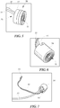
- Fig. 5 is a side perspective view of one of the pressure sensors 50, used in the sensored indentor embodiment of Fig. 1 , and having a diameter slightly less than that of the holes 38 of the shell 30 of Fig. 4 .
- the sensor 50 is a small profile, media compatible, piezoresistive silicon pressure sensor, model 86A, made by Measurement Specialties, but many other sensors could be utilized in other embodiments.
- the sensor 50 includes a cylindrical body 52 and a front side 51 and back side 53. An electrical cable 55 and an air tube 57 are connected to the sensor 50.
- Fig. 6 is a front perspective view of the pressure sensor 50 of Fig. 5 , but with a sleeve 54 applied to provide a tight seal with the holes 38 in the shell 30 of Fig. 4 .
- the sleeve 54 may comprise a rubber material, or other sealing material, and the sensor 50 is press fit into the sleeve.
- An air tube 57 is placed on the sensor vent on the back of the sensor and a silicon rubber (RTV) poured and cured 011 the back 53 of the sensor 50, lo seal the air tube to the sensor vent tube.
- Fig. 7 is a back perspective view of the pressure sensor 50 of Fig. 5 , with the sleeve 54 applied and showing the air tube 57, and the electrical cable 55 which terminates in an electrical connector 59.
- Fig. 8 is bottom perspective view of the shell 30 of Fig. 3 , with the sensors 50 of Fig. 7 placed in the holes 38 of the shell. As seen in this Fig., the front side 51 of the sensors 50 are generally flush with the exterior face of the shell 30.
- the rubber sleeve 54 provides a tight seal between the sensors 50 and the shell 30.
- Fig. 9 is a side perspective view of the shell of Fig. 8 ready to be placed in a mold 60, and for application of gel 54.
- the shell 30 is placed bottom 34 down into the mold 60.
- a gap is maintained between the mold 60 and the exterior surface 61 of the shell 30 such that a gap is present between the mold and the shell's bottom 34 and sides 32.
- the gap may be maintained by using a spacer (e.g. bearing or ball spacer) placed in the bottom of the mold, and a retaining structure, such as a clamp arm system for example and/or additional spacers, to measure and place/maintain the gap at the desired distance between the inside of the mold and the exterior surface 61 of the shell 30.
- a spacer e.g. bearing or ball spacer
- a elastomeric material such as a gel or gelatinous or colloidal material, primarily in fluid form (e.g., heated), is then poured in to the gap between the mold 60 and the shell 30.
- the gel is then allowed to cure, such that it forms the semi-solid or colloidal gel 24 of Fig. 1 .
- the gel 24 may comprise the following formulation: 3 % Dragon Skin® (Smooth-On), 15% Ecoflex® 00-10 (Smooth-On), 48% A-341 Soft Gel (Factor 2), 34% Slacker® (Smooth-on).
- Other gels or sufficiently flexible materials may be used in some embodiments.
- the gel 24 may comprise a gelatinous material that mimics or approximates the flexibility and viscosity properties of human skin and/or tissue.
- the mold can be removed and the indentor 20 of Fig. 1 , with sensors 22 embedded in semi-solid gel is formed.
- the gap can be in a range of suitable thickness to form a gel layer sufficient to mimic human skin and/or tissue (e.g. about 1 ⁇ 4 to 2 inches), and in some embodiments can be about 3/8 inch.
- Fig. 10 is a top perspective view of the sensored indentor embodiment 20 of Fig. 1 , placed on a patient support surface, in this case a hospital bed mattress 63, for testing its contact area and envelopment.
- a cap 64 connected with a mount arm 62 are placed over the shell 30 to allow the indentor 20 to be grasped and controlled.
- the cap 64 includes ports 66 through which wiring and/or air tubes are allowed to exit from the indentor 20.
- the sensors 22 can be seen through the semi-transparent, semi-solid gel 22.
- Fig. 11 is a top perspective view of the sensored indentor 20 of Fig.
- the indentor 20 is lined up in the center of the bed and near the hip region of the mattress, and the force displacement measuring device comprises an INSTRON® measuring system that can control displacement of its arm 72 in conjunction with the force being applied by the arm.
- the system 70 can automatically control the amount of force being applied by the indentor 20 into the flexible top surface of the mattress 63 and simultaneously electronically record the extension distance of the arm 72 at which each such force is reached.
- the system 70 (and/or another system) can receive the pressure readings from the sensors 22 by way of the electrical signals coming from the sensors 22, for each distance and force measured by the system 70. All of this information, and the known distances of each sensor 22 from the apex, can then be used to calculate various performance parameters of the mattress 63, including but not limited to one or more envelopment parameters, as will be described in further detail below.
- the INSTRON® device can be lowered until the indentor 20 touches the mattress 63 or a strip or board placed on the mattress. At that point, the gauge length of the INSTRON® device can be reset, and any strip or board removed. The INSTRON® device can then be controlled by extension, or by force. In some embodiments, the indentor 20 can be pushed into the mattress 63 one inch at a time and held in that position for a period of time (e.g., 60 seconds) while the measurements are being made, until a certain pressure is reached (e.g., 100 mm Hg) at the apex sensor on the indentor 20.
- a period of time e.g. 60 seconds
- the indentor 20 can be extended into the mattress 63 for smaller distances (e.g., 0.25 inches) for the given time periods, while measurements continue to be taken from the sensors and the INSTRON® device, until a final pressure is reached (e.g., 150mm Hg).
- a final pressure e.g. 150mm Hg
- Fig. 12 is a side view of an embodiment of a shell 30' having holes in a concentric ring pattern, made according to one or more principles of the present disclosure, and including a chart showing the distances of each ring from the apex and the previous ring. These distances can be measured such that the distances are known to each pressure sensor to be held in the holes 38'. These distances can then be used to calculate performance parameters.
- Fig. 13 is a schematic diagram of a sphere, illustrating one method of calculating envelopment of a mattress according to one or more principles of the present disclosure.
- an envelopment percentage EP is calculated by dividing the contact area CA of the indentor on the mattress by the immersion area IA of the indentor on the mattress (CA/IA).
- the contact depth can be determined by determining the distance of the ring of sensors to record a (greater than nominal) value from the apex of the indentor. In these embodiments, readings exceeding 1.0mm Hg are considered to exceed nominal, and therefore to have recorded pressure. So, as an example, if it is decided to test a mattress at various forces, and the results in the table below were recorded, and if it was decided that force of most interest is 102.74 lbs, then sensor ring 6 would be chosen as the contact depth.
- the immersion depth is known to be the depth recorded by the force displacement measuring device at the pressure of interest.
- the pressure of interest was 102.74 lbs.
- the corresponding distance output by the measuring device is 6 inches, resulting in an immersion area of 376.8 square inches.
- envelopment percentage EP CA/IA
- Fig. 14 is schematic illustration of three different flexible surfaces 90, 92, and 94 having three different envelopment characteristics when pressed by an indentor 20' at the same force.
- the surface 90 has small contact area CA, primarily at the bottom.
- the surface 92 has greater contact area CA, at the bottom and some of the immersed sides.
- the surface 94 has complete contact area CA at the bottom and immersed sides, corresponding to an envelopment percentage EP of 100%, such as would be obtained by a highly fluidic surface.
- Such characteristics can be measured by the embodiments herein, and using one or more of the principles of this disclosure.
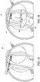
- Fig. 15 is a side view of a pressure chamber 98 that can be used for calibration of a sensored indentor 200 according to one or more principles of the present disclosure.
- Fig. 16 is a side view of the pressure chamber 98 of Fig. 15 but with a sensored indenter 200 placed in the chamber 98.
- Air tubes from the sensors 22 can be run out ports 661 of the indentor 200 through exit tubes in the chamber to atmosphere.
- the electrical cables from the sensors 22 can be run to port 660 and connected to electrical cables 99 from the chamber.
- a known pressure can then be applied by the pressure chamber 98 to apply pressure to the sensors 22 of the indentor 200, and the readings from the sensors recorded by an electronic system. It can then be determined whether any sensor readings need to be adjusted (in software or on the sensor or otherwise) when using the indentor 200 for actual surface testing.
- the chamber 98 can be fitted with a pressure regulator as needed to control the pressure therein.
- various flexible surfaces can be tested using one or more of the principles described herein.
- patient support surfaces can be tested.
- results that may be obtained by using a sensored indentor such as one described herein.
- a selected force such as a 50 th percentile weight load
- the contact depth for this test results in 2.25 inches in each trial. This contact depth is determined by recorded the last ring of sensors to record a pressure beyond nominal.
- the envelopment percentage (shown as envelopment below) for this example can then be calculated as 37.5%.
- the peak pressure of any given sensor may be useful for determine the peak sacral pressure performance of each mattress, under a given load (e.g., 100lbs) using one or more of the sensored indentors described herein.
- the indentor 20 could be used to determine peak interface pressure by attaching the indentor to the INSTRON device, centering the indentor, bringing the indentor to touch the mattress, and resetting the gauge (as described above), and then controlling the INSTRON device to apply a load of 100 lbs for 60 seconds, and recording the peak, mean pressure (in mm Hg).
- the weight limit of each mattress could be measured by pushing down incrementally in force and examining the apex pressure sensor output and looking for a knee in the curve or point on the curve that represents a bottoming out or maximum pressure condition.
- the indentor 20 could be used to determine contact area by attaching and centering and lowering the indentor (as described above), resetting the INSTRON gauge (as described above, and then applying a known force (e.g., 20 lbs) for a time period (e.g., 60 seconds) and continuing to apply pressure in increments (holding for the time period each) until a certain pressure is reached (e.g., equivalent to the 50th percentile weight at 45 degrees head of bed angle).
- the pressures from the sensors 22 can be recorded at each INSTRON pressure increment the contact area determined, such as by using the distance to the highest sensor that recorded an above nominal pressure using the one or more of the methods described herein.
- the immersion, or depth of penetration into a surface can be measured using one or more of the principles herein, as can envelopment or ability to conform to irregularities (or contact area for the given immersion).
- the force displacement measuring device, with attached indentor 20 can be controlled therefore by distance or by pressure, and can be controlled in increments and/or over time, to derive various surface performance characteristics.
- Fig. 17 is a flow diagram illustrating one illustrated method of calculating contact area, immersion area, and an envelopment parameter (in this case an envelopment percentage), according to one or more principles of the present disclosure.
- a test device is provided, as shown at block 170.
- the test device includes sensing points extending upwardly.
- the test device is pressed into a flexible surface.
- the distance D1 that the device gets pressed into the surface is recorded, at block 172.
- the pressures from the sensing points are measured and it is determined how far up D2 on the test device that a greater than nominal pressure is measured.
- contact area is calculated, at block 174.
- immersion area IA is calculated, as shown at block 176.
- an envelopment percentage EP is calculated as shown at block 177.
- the functionality of the methods and operations described herein can be implemented using suitable software, firmware, and /or associated electronics hardware for carrying out the desired tasks.
- the various functionalities described can be programmed as a series of instructions, code, files, or commands using general purpose or special purpose programming languages or programs, and can be executed on one or more general purpose or special purpose computers, processors, devices, other control circuitry, or networks.
- patient or patient support apparatuses can comprise beds, stretchers, chairs, lifts, or equipment to support or transport a patient, for example, or other apparatuses.
- the support surface in some embodiments, can comprise a deck, cushion, frame, seat, or mattress, or portion thereof, or other surface positioned to support the patient.
Landscapes
- General Physics & Mathematics (AREA)
- Physics & Mathematics (AREA)
- Health & Medical Sciences (AREA)
- General Health & Medical Sciences (AREA)
- Life Sciences & Earth Sciences (AREA)
- Nursing (AREA)
- Animal Behavior & Ethology (AREA)
- Public Health (AREA)
- Veterinary Medicine (AREA)
- Chemical & Material Sciences (AREA)
- Analytical Chemistry (AREA)
- Biochemistry (AREA)
- Immunology (AREA)
- Pathology (AREA)
- Force Measurement Appropriate To Specific Purposes (AREA)
Description
- This disclosure relates generally to methods and apparatus for determining performance parameters of patient support surfaces, such as mattresses, cushions, or pads for example. More particularly, but not exclusively, one illustrative embodiment relates an apparatus and method for determining an envelopment parameter of a patient support surface using a test apparatus and method. Moreover, another illustrative embodiment relates to determining an envelopment parameter of a patient support surface and modifying a structural or operational feature of the surface in response to the test results. Examples of known methods and apparatus for determining parameters of support surfaces include:
U.S. patent number 6,220,088, granted on 24 April 2001 in the name of Scales; andU.S. patent number 6,786,083, granted on 7 September 2004 in the name of Bain. - While various test methods and apparatuses have been created for determining characteristics of patient support surfaces, there is still room for improvement. Thus, a need persists for further contributions in this area of technology.
- In one embodiment, a method for determining a characteristic of a flexible surface is provided. The method comprises providing a test device at least part of which having a bottom area and side area. The test device comprises a plurality of sensing points extending from the bottom upwardly toward the side. The method comprises pressing the test device into a flexible surface, measuring the pressures at the sensing points, and determining an envelopment parameter of the surface based on the pressures.
- In another embodiment, a method for determining a characteristic of a patient support surface is provided. The method comprises pressing a test device into a patient support surface, wherein at least part of the test device has a generally rounded shape having a bottom area and a side area. The test device comprises a plurality of sensing points extending from the bottom upwardly toward the side. The method further comprises measuring the pressures at the sensing points, transmitting signals representing the pressures from the sensing points to a data device, storing pressure data representing the pressures in the data device, and determining an envelopment parameter of the surface based on the pressure data.
- A test indentor may also be provided comprising a shell, at least a portion of which is generally round in shape and having an exterior. The indentor further comprises a plurality of pressure sensor points extending along the side of the shell, each sensing point capable of detecting pressure at its location. The indentor further comprises an elastomeric material on the exterior of the shell and adjacent the sensing points.
- A method of manufacturing a sensored indentor may also be provided. The method comprises providing a shell, securing pressure sensors to the exterior of the shell, placing the shell into a mold while maintaining a gap between the shell and the mold. The method further comprises pouring a fluid material into the gap, and allowing the fluid material to cure.
- Additional features, alone or in combination with any other feature(s), including those listed above and those listed in the claims and those described in detail below, can comprise patentable subject matter. Others will become apparent to those skilled in the art upon consideration of the following detailed description of illustrative embodiments exemplifying the best mode of carrying out the invention as presently perceived.
- Referring now to the illustrated examples in the drawings, wherein like numerals represent the same or similar elements throughout:
-
Fig. 1 is a bottom view of an illustrative embodiment of a sensored indentor, made and operating according to one or more principles of the present disclosure; -
Fig. 2 is a top perspective view of the shell component of the sensored indentor ofFIG. 1 , prior to having holes placed therein; -
Fig. 3 is a bottom view of the shell ofFig. 2 , after having holes placed therein, in a spaced and circular pattern of rings; -
Fig. 4 is a side view of the shell ofFig. 3 ; -
Fig. 5 is a side perspective view of one of the pressure sensors used in the sensored indentor embodiment ofFig. 1 ; -
Fig. 6 is a front perspective view of the pressure sensor ofFig. 5 , but with the sleeve applied; -
Fig. 7 is a back perspective view of the pressure sensor ofFig. 5 , with the sleeve applied and showing the electrical cable and its connector, and the calibration air tube; -
Fig. 8 is bottom perspective view of the shell ofFig. 3 , with the sensors ofFig. 7 placed in the holes; -
Fig. 9 is a side perspective view of the shell ofFig. 8 ready to be placed in a mold, for application of gel; -
Fig. 10 is a top perspective view of the sensored indentor ofFig. 1 , placed on a mattress for testing its contact area and envelopment; -
Fig. 11 is a top perspective view of the sensored indentor ofFig. 1 connected to a force displacement measuring device, and placed on a mattress for testing its contact area and envelopment; -
Fig. 12 is a side view of an embodiment of a shell having holes in a concentric ring pattern, made according to one or more principles of the present disclosure, and including a chart showing the distances of each ring from the apex and the previous ring; -
Fig. 13 is a schematic diagram of a sphere, illustrating one method of calculating envelopment of a mattress according to one or more principles of the present disclosure; -
Fig. 14 is schematic illustration of three different surfaces having three different envelopment characteristics; -
Fig. 15 is a side view of a pressure chamber that can be used for calibration of a sensored indentor according to one or more principles of the present disclosure; -
Fig. 16 is a side view of the pressure chamber ofFig. 15 but with a sensored indenter placed in the chamber; and -
Fig. 17 is a flow diagram illustrating one illustrated method of calculating contact area, immersion area, and an envelopment parameter (in this case an envelopment percentage), according to one or more principles of the present disclosure. - Embodiments that incorporate one or more principles of the present disclosure can take many different forms. However, for the purpose of promoting an understanding of the principles of the disclosure, reference will now be made to the embodiments illustrated in the drawings, and specific language will be used to describe the same. No limitation of the scope of the disclosure is thereby intended. Many alterations and modifications of the described embodiments, and various applications of the principles of the disclosure described herein, are contemplated.
-
Fig. 1 is a bottom view of an illustrative embodiment of asensored indentor 20, made and operating according to one or more principles of the present disclosure. In this embodiment, the indentor is hemispherical in shape and includes abottom area 21b and aside area 21s. A plurality ofpressure sensors 22 are embedded in theindentor 20, beneath a layer ofgel 24. Thesensors 22 can be seen through thesemi-transparent gel 24. Beneath thegel 24 are a rigid shell having sensors placed therein, as will be described in more detail below. Thesensors 22 are spaced from the bottom/apex sensor, moving upwardly along theside 21b, in a plurality of locations (23, 25, 27, 29, 31) at known distances from the apex. As will be described in more detail below, in this embodiment thesensors 22 are placed in a plurality of concentric spaced rings moving upwardly along the hemisphere starting from the apex, the distances between the rings and the apex being known. -
Fig. 2 is a top perspective view of theshell component 30 of the sensored indentor ofFIG. 1 , prior to having holes placed therein. Theshell 30 of this embodiment is a partial sphere and includes abottom 34 that transitions seamlessly intosides 32. In this example, the shell includes awall 36 that makes up theshell 30 and a hollow center surrounded by thewall 36. The shell may be made of a variety of rigid materials, such as urethane, plastic, metal, wood, composites, and the like. -
Fig. 3 is a bottom view of theshell 30 ofFig. 2 , after havingholes 38 placed therein, in a spaced and circular pattern of rings. An apex hole A is placed at the apex of theshell 32 in thebottom area 34. Moving upwardly from the apex hole A and along theside area 32 of theshell 30,additional holes 38 are placed alongconcentric rings Fig. 4 is a side view of theshell 30 ofFig. 3 . As shown inFIG. 4 , the distances d1-d11, between each of the rings (31, 33, 35, 37, 39, 41, 43, 45, 47, and 49) and its adjacent ring, are known, as is the overall distance of each of the rings to the Apex (A). This can be achieved, for example, by measuring off the distances d1-d11 to what is desired, and drawing or marking the rings on theshell 30. Theholes 38 are then placed or formed in theshell 30, and are sized to fit corresponding pressure sensors, such as those shown inFIG. 5 . Theshell 30 has a radius that approximates the shape of the buttocks of a human, such as in the range of the 25-75 percentile male for example, or about the 50% male for instance. In some embodiments the radius can be selected to be between about 8 and about 12 inches, and in some embodiments can be selected to be about 10 inches. - More particularly,
Fig. 5 is a side perspective view of one of thepressure sensors 50, used in the sensored indentor embodiment ofFig. 1 , and having a diameter slightly less than that of theholes 38 of theshell 30 ofFig. 4 . In this embodiment, thesensor 50 is a small profile, media compatible, piezoresistive silicon pressure sensor, model 86A, made by Measurement Specialties, but many other sensors could be utilized in other embodiments. Thesensor 50 includes acylindrical body 52 and afront side 51 and backside 53. Anelectrical cable 55 and anair tube 57 are connected to thesensor 50. -
Fig. 6 is a front perspective view of thepressure sensor 50 ofFig. 5 , but with asleeve 54 applied to provide a tight seal with theholes 38 in theshell 30 ofFig. 4 . Thesleeve 54 may comprise a rubber material, or other sealing material, and thesensor 50 is press fit into the sleeve. Anair tube 57 is placed on the sensor vent on the back of the sensor and a silicon rubber (RTV) poured and cured 011 theback 53 of thesensor 50, lo seal the air tube to the sensor vent tube.Fig. 7 is a back perspective view of thepressure sensor 50 ofFig. 5 , with thesleeve 54 applied and showing theair tube 57, and theelectrical cable 55 which terminates in anelectrical connector 59. -
Fig. 8 is bottom perspective view of theshell 30 ofFig. 3 , with thesensors 50 ofFig. 7 placed in theholes 38 of the shell. As seen in this Fig., thefront side 51 of thesensors 50 are generally flush with the exterior face of theshell 30. Therubber sleeve 54 provides a tight seal between thesensors 50 and theshell 30. -
Fig. 9 is a side perspective view of the shell ofFig. 8 ready to be placed in amold 60, and for application ofgel 54. In this embodiment, theshell 30 is placed bottom 34 down into themold 60. A gap is maintained between themold 60 and theexterior surface 61 of theshell 30 such that a gap is present between the mold and the shell's bottom 34 and sides 32. The gap may be maintained by using a spacer (e.g. bearing or ball spacer) placed in the bottom of the mold, and a retaining structure, such as a clamp arm system for example and/or additional spacers, to measure and place/maintain the gap at the desired distance between the inside of the mold and theexterior surface 61 of theshell 30. A elastomeric material, such as a gel or gelatinous or colloidal material, primarily in fluid form (e.g., heated), is then poured in to the gap between themold 60 and theshell 30. The gel is then allowed to cure, such that it forms the semi-solid orcolloidal gel 24 ofFig. 1 . Thegel 24 may comprise the following formulation: 3 % Dragon Skin® (Smooth-On), 15% Ecoflex® 00-10 (Smooth-On), 48% A-341 Soft Gel (Factor 2), 34% Slacker® (Smooth-on). However, other gels or sufficiently flexible materials may be used in some embodiments. In some embodiments, thegel 24 may comprise a gelatinous material that mimics or approximates the flexibility and viscosity properties of human skin and/or tissue. Once the liquid gel cures in themold 60, the mold can be removed and theindentor 20 ofFig. 1 , withsensors 22 embedded in semi-solid gel is formed. In some embodiments the gap can be in a range of suitable thickness to form a gel layer sufficient to mimic human skin and/or tissue (e.g. about ¼ to 2 inches), and in some embodiments can be about 3/8 inch. -
Fig. 10 is a top perspective view of thesensored indentor embodiment 20 ofFig. 1 , placed on a patient support surface, in this case ahospital bed mattress 63, for testing its contact area and envelopment. Acap 64 connected with amount arm 62 are placed over theshell 30 to allow theindentor 20 to be grasped and controlled. Thecap 64 includesports 66 through which wiring and/or air tubes are allowed to exit from theindentor 20. InFig. 10 , thesensors 22 can be seen through the semi-transparent,semi-solid gel 22.Fig. 11 is a top perspective view of thesensored indentor 20 ofFig. 1 connected to a forcedisplacement measuring device 70, and placed on themattress 63 for testing its contact area and envelopment. In this embodiment, theindentor 20 is lined up in the center of the bed and near the hip region of the mattress, and the force displacement measuring device comprises an INSTRON® measuring system that can control displacement of itsarm 72 in conjunction with the force being applied by the arm. Accordingly, thesystem 70 can automatically control the amount of force being applied by theindentor 20 into the flexible top surface of themattress 63 and simultaneously electronically record the extension distance of thearm 72 at which each such force is reached. The system 70 (and/or another system) can receive the pressure readings from thesensors 22 by way of the electrical signals coming from thesensors 22, for each distance and force measured by thesystem 70. All of this information, and the known distances of eachsensor 22 from the apex, can then be used to calculate various performance parameters of themattress 63, including but not limited to one or more envelopment parameters, as will be described in further detail below. - In some embodiments, the INSTRON® device can be lowered until the
indentor 20 touches themattress 63 or a strip or board placed on the mattress. At that point, the gauge length of the INSTRON® device can be reset, and any strip or board removed. The INSTRON® device can then be controlled by extension, or by force. In some embodiments, theindentor 20 can be pushed into themattress 63 one inch at a time and held in that position for a period of time (e.g., 60 seconds) while the measurements are being made, until a certain pressure is reached (e.g., 100 mm Hg) at the apex sensor on theindentor 20. Thereafter, theindentor 20 can be extended into themattress 63 for smaller distances (e.g., 0.25 inches) for the given time periods, while measurements continue to be taken from the sensors and the INSTRON® device, until a final pressure is reached (e.g., 150mm Hg). -
Fig. 12 is a side view of an embodiment of a shell 30' having holes in a concentric ring pattern, made according to one or more principles of the present disclosure, and including a chart showing the distances of each ring from the apex and the previous ring. These distances can be measured such that the distances are known to each pressure sensor to be held in the holes 38'. These distances can then be used to calculate performance parameters.Fig. 13 is a schematic diagram of a sphere, illustrating one method of calculating envelopment of a mattress according to one or more principles of the present disclosure. In this embodiment, an envelopment percentage EP is calculated by dividing the contact area CA of the indentor on the mattress by the immersion area IA of the indentor on the mattress (CA/IA). The contact area can be calculatn according to the following formula:
- In the embodiments of
Figs 11 and12 , the contact depth can be determined by determining the distance of the ring of sensors to record a (greater than nominal) value from the apex of the indentor. In these embodiments, readings exceeding 1.0mm Hg are considered to exceed nominal, and therefore to have recorded pressure. So, as an example, if it is decided to test a mattress at various forces, and the results in the table below were recorded, and if it was decided that force of most interest is 102.74 lbs, thensensor ring 6 would be chosen as the contact depth. Since it is known thatsensor ring 6 is 3 inches from the apex in this example, and the radius r of the shell is known to be 10 inches, the contact area (for the 102.74 lb test) is calculated to be 188.4 square inches as shown below:
• Determine Contact Depth as last ring with mean IFP > 1.0 mm Hg (inches)
• Contact Area = 2 * π * radiusMean Pressures (mm Hg) by Ring at each Instron Force Level Insron Foce lbF Base Ring 1 Ring 2Ring 3Ring 4Ring 5Ring 6Ring 7Ring 8Ring 9Ring 1020.47 24.58 23.41 19.85 15.62 11.78 0.66 -0.08 •0.18 •0.15 •0.16 •0.18 32.99 28.31 27.73 25.59 22.65 16.38 8.89 0.13 •0.13 •0.15 •0.17 •0.18 47.75 35.17 33.88 30.99 27.99 21.11 15.10 1.09 •0.03 •0.13 •0.17 •0.18 64.46 49.68 45.57 38.03 33.18 25.19 18.50 4.77 0.10 •0.10 •0.16 •0.18 03.15 71.31 62.35 46.97 38.39 28.72 20.77 8.62 0.25 •0.07 •0.15 •0.18 102.74 100.81 83.96 56.78 43.68 32.04 22.84 11.45 0.40 •0.04 •0.15 •0.18 MEAN 51.64 46.15 36.42 30.25 22.54 14.46 4.33 0.07 •0.11 •0.16 •0.18 Dist from Apex (Ins.) 0.00 0.13 0.38 0.75 1.50 2.25 3.00 3.75 4.50 5.25 6.00 
- The immersion area IA for this example can be calculated as well according to the following formula:

- The immersion depth is known to be the depth recorded by the force displacement measuring device at the pressure of interest. In this example, if the pressure of interest was 102.74 lbs., the corresponding distance output by the measuring device is 6 inches, resulting in an immersion area of 376.8 square inches. Because envelopment percentage EP = CA/IA, the resulting EP for 102.74 lbs. for the mattress of this example is 188.4 / 376.8 = 50%
-
Fig. 14 is schematic illustration of three differentflexible surfaces surface 90 has small contact area CA, primarily at the bottom. Thesurface 92 has greater contact area CA, at the bottom and some of the immersed sides. Thesurface 94 has complete contact area CA at the bottom and immersed sides, corresponding to an envelopment percentage EP of 100%, such as would be obtained by a highly fluidic surface. Such characteristics can be measured by the embodiments herein, and using one or more of the principles of this disclosure. - Calibration of the
sensors 22 of the indentor may be necessary in some circumstances.Fig. 15 is a side view of apressure chamber 98 that can be used for calibration of asensored indentor 200 according to one or more principles of the present disclosure.Fig. 16 is a side view of thepressure chamber 98 ofFig. 15 but with asensored indenter 200 placed in thechamber 98. Air tubes from thesensors 22 can be run out ports 661 of theindentor 200 through exit tubes in the chamber to atmosphere. The electrical cables from thesensors 22 can be run toport 660 and connected toelectrical cables 99 from the chamber. A known pressure can then be applied by thepressure chamber 98 to apply pressure to thesensors 22 of theindentor 200, and the readings from the sensors recorded by an electronic system. It can then be determined whether any sensor readings need to be adjusted (in software or on the sensor or otherwise) when using theindentor 200 for actual surface testing. Thechamber 98 can be fitted with a pressure regulator as needed to control the pressure therein. - Accordingly, various flexible surfaces can be tested using one or more of the principles described herein. For example, patient support surfaces can be tested. Below is an example of results that may be obtained by using a sensored indentor such as one described herein. In the first row of this example, a selected force (such as a 50th percentile weight load) was applied on the
LAL# 1 mattress resulted in an indentor immersion of 6 inches as measured by the force displacement measuring device. The contact depth for this test results in 2.25 inches in each trial. This contact depth is determined by recorded the last ring of sensors to record a pressure beyond nominal. The envelopment percentage (shown as envelopment below) for this example can then be calculated as 37.5%. Other parameters can also be calculated or otherwise determined which may be useful using one or more of the embodiments and/or principles herein. For example, the peak pressure of any given sensor may be useful for determine the peak sacral pressure performance of each mattress, under a given load (e.g., 100lbs) using one or more of the sensored indentors described herein. For instance, theindentor 20 could be used to determine peak interface pressure by attaching the indentor to the INSTRON device, centering the indentor, bringing the indentor to touch the mattress, and resetting the gauge (as described above), and then controlling the INSTRON device to apply a load of 100 lbs for 60 seconds, and recording the peak, mean pressure (in mm Hg). As another example, the weight limit of each mattress could be measured by pushing down incrementally in force and examining the apex pressure sensor output and looking for a knee in the curve or point on the curve that represents a bottoming out or maximum pressure condition. As a further example, theindentor 20 could be used to determine contact area by attaching and centering and lowering the indentor (as described above), resetting the INSTRON gauge (as described above, and then applying a known force (e.g., 20 lbs) for a time period (e.g., 60 seconds) and continuing to apply pressure in increments (holding for the time period each) until a certain pressure is reached (e.g., equivalent to the 50th percentile weight at 45 degrees head of bed angle). The pressures from thesensors 22 can be recorded at each INSTRON pressure increment the contact area determined, such as by using the distance to the highest sensor that recorded an above nominal pressure using the one or more of the methods described herein. As also noted herein, the immersion, or depth of penetration into a surface, can be measured using one or more of the principles herein, as can envelopment or ability to conform to irregularities (or contact area for the given immersion). The force displacement measuring device, with attachedindentor 20, can be controlled therefore by distance or by pressure, and can be controlled in increments and/or over time, to derive various surface performance characteristics.(Envelopment) ↓ Contact Depth in inches.: (Last Ring with Mean P > 1.00 mm Hg Surface Indentor Inmerson (in.) Trial # 1Trial # 2Trial # 3Trial # 4Trial # 5Trial # 6Trial # 7Trial # 8Trial # 9Trial # 10Mean Meanlmmersion % (Contact Depth/ Imm) St Dev LAL#1 (topper with spacing material) 6.00 2.25 2.25 2.25 2.25 2.25 2.25 2.25 2.25 2.25 2.25 2.25 37.5% 0.0% LAL #2 (no topper) 9.00 4.50 4.50 4.50 4.50 4.50 4.50 4.50 4.50 4.50 4.50 4.50 50.0% 0.0% Visco Foam 5.25 3.00 3.00 13.00 3.00 3.00 3.00 3.00 3.00 3.00 3.00 3.00 57.1% 0.0% Gel 6.00 3.00 3.00 3.00 3.00 3.00 3.00 3.00 3.00 3.00 3.00 3.00 57.1% 0.0% Zoned foam 5.25 3.00 3.00 3.00 3.00 3.00 3.00 3.00 3.00 3.00 3.00 3.00 57.1% 0.0% AFT-Head 5.00 5.00 5.00 5.00 5.00 5.00 5,00 5.00 5.00 5.00 5.00 5.00 100.0% 0.0% AFT - foot 5.00 5.00 5.00 5.00 5.00 5.00 5.00 5.00 5.00 5.00 5.00 5.00 100.0% 0.0% -
Fig. 17 is a flow diagram illustrating one illustrated method of calculating contact area, immersion area, and an envelopment parameter (in this case an envelopment percentage), according to one or more principles of the present disclosure. In this example, a test device is provided, as shown atblock 170. The test device includes sensing points extending upwardly. As shown atblock 171, the test device is pressed into a flexible surface. The distance D1 that the device gets pressed into the surface is recorded, atblock 172. As shown atblock 173, the pressures from the sensing points are measured and it is determined how far up D2 on the test device that a greater than nominal pressure is measured. From D2, contact area is calculated, atblock 174. From D1, immersion area IA is calculated, as shown atblock 176. From CA and IA, an envelopment percentage EP is calculated as shown atblock 177. - The embodiments above, and additional embodiments, can be known and understood from the attached Appendix A. One or more of the disclosures and aspects of Appendix A can be used in conjunction or as an alternative to one or more of the aspects of the embodiments described herein, as will be understood.
- As can be understood, the functionality of the methods and operations described herein can be implemented using suitable software, firmware, and /or associated electronics hardware for carrying out the desired tasks. For instance, the various functionalities described can be programmed as a series of instructions, code, files, or commands using general purpose or special purpose programming languages or programs, and can be executed on one or more general purpose or special purpose computers, processors, devices, other control circuitry, or networks.
- As can also be understood from reviewing the various embodiments above, many additional embodiments other than those described herein are possible and still included in the spirit and scope of the claims defining the inventions herein. For instance, sensors other than pressure sensors could be utilized, such as shear sensors for example, in some embodiments. In some embodiments, patient or patient support apparatuses can comprise beds, stretchers, chairs, lifts, or equipment to support or transport a patient, for example, or other apparatuses. The support surface, in some embodiments, can comprise a deck, cushion, frame, seat, or mattress, or portion thereof, or other surface positioned to support the patient.
- Any theory, mechanism of operation, proof, or finding stated herein is meant to further enhance understanding of principles of the present disclosure and is not intended to make the present disclosure in any way dependent upon such theory, mechanism of operation, illustrative embodiment, proof, or finding. In reading the claims it is intended that when words such as "a," "an," "at least one," "at least a portion" are used there is no intention to limit the claim to only one item unless specifically stated to the contrary in the claim. When the language "at least a portion" and/or "a portion" is used the item can include a portion and/or the entire item unless specifically stated to the contrary.
Claims (7)
- A method for determining a characteristic of a patient support surface, the method comprising:pressing a test device into a patient support surface, wherein at least part of the test device has a generally rounded shape having a bottom area (21b, 34) and a side area (21s, 32), the test device comprising a plurality of sensing points extending from the bottom area (21b, 34) upwardly toward the side area (21s, 32);measuring the pressures at the sensing points;transmitting signals representing the pressures from the sensing points to a data device; andstoring pressure data representing the pressures in the data device,characterised in that:the pressing operation is carried out at a controlled force by a measuring device;the measuring device comprises a force displacement measuring device (70);the measuring device presses the test device into the patient support surface at a known force and records displacement data indicating how far the test device has been pressed into the patient support surface; andthe method further comprises determining an envelopment parameter of the surface based on a contact area determined from the pressure data and an immersion parameter determined from the displacement data.
- The method as recited in claim 1, wherein the envelopment parameter is determined by dividing the contact area (CA) by the immersion area (IA), wherein CA and IA are calculated by the following formulas:


- The method as recited in claim 2, wherein the contact depth is determined by the height from the bottom area (34) of the test device of the sensing point that measures a pressure exceeding a nominal pressure.
- The method as recited in claim 2, wherein the immersion depth is calculated by measuring how far down the test device has been pressed into the support surface.
- The method as recited in claim 1, wherein the envelopment parameter is an envelopment percentage (EP) determined by the following equation:

- The method as recited in claim 5, wherein the contact depth is determined by the distance to the highest sensing point that senses a pressure that is greater than a nominal value, and the immersion depth is determined by measuring the distance that the test device has been pressed into the patient support surface.
- The method as recited in claim 6, wherein the distance that the test device has been pressed into the patient support surface is determined by the force displacement measuring device (70) that automatically carries out the pressing step until a predetermined pressure is reached.
Applications Claiming Priority (2)
| Application Number | Priority Date | Filing Date | Title |
|---|---|---|---|
| US201361845685P | 2013-07-12 | 2013-07-12 | |
| PCT/US2014/045893 WO2015006407A1 (en) | 2013-07-12 | 2014-07-09 | Apparatuses and methods for determining performance parameters of a flexible surface |
Publications (3)
| Publication Number | Publication Date |
|---|---|
| EP3019844A1 EP3019844A1 (en) | 2016-05-18 |
| EP3019844A4 EP3019844A4 (en) | 2016-08-03 |
| EP3019844B1 true EP3019844B1 (en) | 2018-05-02 |
Family
ID=52280551
Family Applications (1)
| Application Number | Title | Priority Date | Filing Date |
|---|---|---|---|
| EP14823793.6A Not-in-force EP3019844B1 (en) | 2013-07-12 | 2014-07-09 | Apparatuses and methods for determining performance parameters of a flexible surface |
Country Status (3)
| Country | Link |
|---|---|
| US (1) | US10337963B2 (en) |
| EP (1) | EP3019844B1 (en) |
| WO (1) | WO2015006407A1 (en) |
Families Citing this family (21)
| Publication number | Priority date | Publication date | Assignee | Title |
|---|---|---|---|---|
| US11559421B2 (en) | 2015-06-25 | 2023-01-24 | Hill-Rom Services, Inc. | Protective dressing with reusable phase-change material cooling insert |
| US10489661B1 (en) | 2016-03-08 | 2019-11-26 | Ocuvera LLC | Medical environment monitoring system |
| US10600204B1 (en) | 2016-12-28 | 2020-03-24 | Ocuvera | Medical environment bedsore detection and prevention system |
| DE102017200315B4 (en) * | 2017-01-11 | 2026-06-25 | Bayerische Motoren Werke Aktiengesellschaft | Device and method for testing at least one seat component for a motor vehicle |
| US11246775B2 (en) | 2017-12-28 | 2022-02-15 | Stryker Corporation | Patient turning device for a patient support apparatus |
| US11173085B2 (en) | 2017-12-28 | 2021-11-16 | Stryker Corporation | Mattress cover for a mattress providing rotation therapy to a patient |
| US11583437B2 (en) | 2018-02-06 | 2023-02-21 | Aspen Surgical Products, Inc. | Reusable warming blanket with phase change material |
| USD877915S1 (en) | 2018-09-28 | 2020-03-10 | Stryker Corporation | Crib assembly |
| USD888962S1 (en) | 2018-09-28 | 2020-06-30 | Stryker Corporation | Cover assembly for a patient support |
| USD977109S1 (en) | 2018-09-28 | 2023-01-31 | Stryker Corporation | Crib assembly for a patient support |
| USD879966S1 (en) | 2018-09-28 | 2020-03-31 | Stryker Corporation | Crib assembly |
| USD888964S1 (en) | 2018-09-28 | 2020-06-30 | Stryker Corporation | Crib assembly for a patient support |
| USD888963S1 (en) | 2018-09-28 | 2020-06-30 | Stryker Corporation | Cover assembly for a patient support |
| USD894956S1 (en) | 2018-10-31 | 2020-09-01 | Stryker Corporation | Display screen or portion thereof with graphical user interface |
| USD893543S1 (en) | 2018-10-31 | 2020-08-18 | Stryker Corporation | Display screen with graphical user interface |
| USD890914S1 (en) | 2018-10-31 | 2020-07-21 | Stryker Corporation | Pump |
| USD892159S1 (en) | 2018-10-31 | 2020-08-04 | Stryker Corporation | Display screen with animated graphical user interface |
| USD894957S1 (en) | 2018-10-31 | 2020-09-01 | Stryker Corporation | Display screen or portion thereof with graphical user interface |
| USD894223S1 (en) | 2018-10-31 | 2020-08-25 | Stryker Corporation | Display screen with animated graphical user interface |
| USD894226S1 (en) | 2018-10-31 | 2020-08-25 | Stryker Corporation | Display screen or portion thereof with graphical user interface |
| US12181372B2 (en) * | 2021-09-23 | 2024-12-31 | Raptor Tech Inc. | Stabilizer mat test system and methods |
Family Cites Families (29)
| Publication number | Priority date | Publication date | Assignee | Title |
|---|---|---|---|---|
| US2154561A (en) | 1937-07-12 | 1939-04-18 | Chrysler Corp | Cushion testing apparatus |
| US2378039A (en) | 1942-04-30 | 1945-06-12 | Abraham W Schenker | Device for measuring pressures exerted by certain body portions on a support therefor |
| US2644332A (en) | 1951-02-24 | 1953-07-07 | Robinson Furniture Company | Weight distribution testing apparatus |
| US3195347A (en) | 1962-05-17 | 1965-07-20 | Wortso Corp | Bedding testing machine |
| US3334517A (en) | 1964-12-23 | 1967-08-08 | Wortso Corp | Mattress testing apparatus |
| US3413849A (en) | 1965-12-30 | 1968-12-03 | Wortso Corp | Laboratory bedding test machine |
| US4004457A (en) * | 1976-01-13 | 1977-01-25 | The United States Bedding Company | Compression tester |
| US4140008A (en) * | 1977-12-27 | 1979-02-20 | The United States Bedding Company | System for testing firmness |
| US4267728A (en) | 1978-07-04 | 1981-05-19 | Manley Michael T | Apparatus for analyzing the forces acting on a human foot |
| EP0085813B1 (en) * | 1981-12-28 | 1986-06-11 | Olympus Optical Co., Ltd. | Tubular probe for sensing hardness variations when rubbed over a surface to be examined |
| US4964302A (en) | 1984-09-25 | 1990-10-23 | Grahn Allen R | Tactile sensor |
| US4669302A (en) * | 1985-04-24 | 1987-06-02 | Sealy, Incorporated | Deflection and topography assessment mechanism anthropomorphically natural |
| US4827763A (en) | 1986-04-11 | 1989-05-09 | Purdue Research Foundation | Pressure mapping system with capacitive measuring pad |
| WO1993014386A1 (en) | 1987-11-05 | 1993-07-22 | Kikuo Kanaya | Distribution-type touch sensor |
| DE3918195A1 (en) * | 1988-06-08 | 1989-12-21 | Ingenieurdienst Fuer Sichere T | Method and device for detecting, picking up and measuring the elastic and elastoplastic deformation of a surface of a test-piece arising under the effect of a load |
| US5253656A (en) * | 1991-05-23 | 1993-10-19 | Rincoe Richard G | Apparatus and method for monitoring contact pressure between body parts and contact surfaces |
| US5148706A (en) | 1991-05-29 | 1992-09-22 | France Bed Co., Ltd. | Apparatus for selecting mattress |
| DE4131257A1 (en) | 1991-09-17 | 1993-03-25 | Rolf Wesemann | DEVICE FOR MEASURING PRESSURE ON A BASE |
| US5524636A (en) | 1992-12-21 | 1996-06-11 | Artann Corporation Dba Artann Laboratories | Method and apparatus for elasticity imaging |
| US5375397B1 (en) | 1993-06-22 | 1998-11-10 | Robert J Ferrand | Curve-conforming sensor array pad and method of measuring saddle pressures on a horse |
| GB9320864D0 (en) | 1993-10-11 | 1993-12-01 | Scales John T | Assessment of patient support systems |
| US5970789A (en) * | 1996-11-20 | 1999-10-26 | Hill-Rom, Inc. | Method and apparatus for evaluating a support surface |
| US6179790B1 (en) * | 1997-10-20 | 2001-01-30 | Assurance Medical, Inc. | Layer of material for use with tissue examination device |
| GB9905005D0 (en) * | 1999-03-05 | 1999-04-28 | Bain Duncan S | Portable device for the assessment of mattresses |
| AU4215200A (en) | 1999-04-07 | 2000-10-23 | L&P Property Management Company | Customized mattress system |
| JPWO2003036247A1 (en) * | 2001-10-22 | 2005-09-29 | マイクロジェニックス株式会社 | Pressure sensor and monitor using the pressure sensor |
| US20040068203A1 (en) * | 2002-10-03 | 2004-04-08 | Scimed Life Systems, Inc. | Sensing pressure |
| KR20090064308A (en) * | 2007-12-14 | 2009-06-18 | 현대자동차주식회사 | Human Body Model for Seat Convenience Evaluation |
| US8770020B2 (en) | 2008-02-14 | 2014-07-08 | Kingsdown, Inc. | Methods and apparatuses for testing a sleep support member |
-
2014
- 2014-07-09 US US14/901,295 patent/US10337963B2/en active Active
- 2014-07-09 EP EP14823793.6A patent/EP3019844B1/en not_active Not-in-force
- 2014-07-09 WO PCT/US2014/045893 patent/WO2015006407A1/en not_active Ceased
Non-Patent Citations (1)
| Title |
|---|
| None * |
Also Published As
| Publication number | Publication date |
|---|---|
| EP3019844A4 (en) | 2016-08-03 |
| US10337963B2 (en) | 2019-07-02 |
| EP3019844A1 (en) | 2016-05-18 |
| US20160356676A1 (en) | 2016-12-08 |
| WO2015006407A1 (en) | 2015-01-15 |
Similar Documents
| Publication | Publication Date | Title |
|---|---|---|
| US10337963B2 (en) | Apparatuses and methods for determining performance parameters of a flexible surface | |
| EP4606364A1 (en) | Beds and other body support devices with individually controllable cells comprising one or more air bladders | |
| US20130074262A1 (en) | Automatic patient weight measurement for determining pressure relief set points | |
| US9504336B2 (en) | Configurable bed | |
| US20190151160A1 (en) | Pressure sensor | |
| US6220088B1 (en) | Assessment of patient support systems | |
| JP6401149B2 (en) | Physiological sensor | |
| US10768040B2 (en) | Transfer and weighing device | |
| EP3017762A1 (en) | Pneumatic tocodynamometer | |
| CN108051054A (en) | It is a kind of in hospital can intelligent measure height and weight measuring instrument | |
| US20220313182A1 (en) | Mattress having selectable patient weight valve, inductive power, and a digital x-ray cassette | |
| US7842892B2 (en) | Apparatus and method for measuring the body weight | |
| KR20230160841A (en) | Test Methods for Assessing Spine or Skeletal Alignment | |
| CN105280067A (en) | Multi-gravity simulation living care bed | |
| Hoffmann et al. | Towards embedded force sensors in exoskeletons for evaluating interaction forces in interfaces | |
| JP7553098B2 (en) | Method and device for measuring contact pressure of body support equipment | |
| Mallick et al. | Performance Evaluation of Neonatal Anti-Pressure Ulcer Bed Using a Novel Force-Sensing Array | |
| US9693916B2 (en) | Anti-decubitus ulcer mattress overlay system with selective elevation structure | |
| IT202100005522A1 (en) | ANTI-DECUBITUS SYSTEM. | |
| WO2014188434A1 (en) | Registering apparatus | |
| US20250160685A1 (en) | Pressure based presence monitoring systems and methods of monitoring presence based on pressure | |
| KR20220112015A (en) | IoT-based Smart Sensing Medical Mat for the Prevention of Barbar Disease | |
| JP2009244247A (en) | Cylinder expanding type contact pressure calibration method | |
| JP3637552B2 (en) | Weight bed | |
| TW201302156A (en) | Constant pressure system for human body detector |
Legal Events
| Date | Code | Title | Description |
|---|---|---|---|
| PUAI | Public reference made under article 153(3) epc to a published international application that has entered the european phase |
Free format text: ORIGINAL CODE: 0009012 |
|
| 17P | Request for examination filed |
Effective date: 20160209 |
|
| AK | Designated contracting states |
Kind code of ref document: A1 Designated state(s): AL AT BE BG CH CY CZ DE DK EE ES FI FR GB GR HR HU IE IS IT LI LT LU LV MC MK MT NL NO PL PT RO RS SE SI SK SM TR |
|
| AX | Request for extension of the european patent |
Extension state: BA ME |
|
| A4 | Supplementary search report drawn up and despatched |
Effective date: 20160701 |
|
| RIC1 | Information provided on ipc code assigned before grant |
Ipc: G01L 7/00 20060101AFI20160627BHEP Ipc: G01L 1/20 20060101ALI20160627BHEP Ipc: G01M 99/00 20110101ALI20160627BHEP Ipc: A47C 31/12 20060101ALI20160627BHEP Ipc: G01N 3/40 20060101ALI20160627BHEP |
|
| DAX | Request for extension of the european patent (deleted) | ||
| GRAP | Despatch of communication of intention to grant a patent |
Free format text: ORIGINAL CODE: EPIDOSNIGR1 |
|
| RIC1 | Information provided on ipc code assigned before grant |
Ipc: G01L 7/00 20060101AFI20171031BHEP Ipc: G01L 1/20 20060101ALI20171031BHEP Ipc: G01M 99/00 20110101ALI20171031BHEP Ipc: A47C 31/12 20060101ALI20171031BHEP Ipc: G01N 3/40 20060101ALI20171031BHEP |
|
| INTG | Intention to grant announced |
Effective date: 20171129 |
|
| GRAS | Grant fee paid |
Free format text: ORIGINAL CODE: EPIDOSNIGR3 |
|
| GRAA | (expected) grant |
Free format text: ORIGINAL CODE: 0009210 |
|
| AK | Designated contracting states |
Kind code of ref document: B1 Designated state(s): AL AT BE BG CH CY CZ DE DK EE ES FI FR GB GR HR HU IE IS IT LI LT LU LV MC MK MT NL NO PL PT RO RS SE SI SK SM TR |
|
| REG | Reference to a national code |
Ref country code: GB Ref legal event code: FG4D |
|
| REG | Reference to a national code |
Ref country code: CH Ref legal event code: EP Ref country code: AT Ref legal event code: REF Ref document number: 995789 Country of ref document: AT Kind code of ref document: T Effective date: 20180515 |
|
| REG | Reference to a national code |
Ref country code: DE Ref legal event code: R096 Ref document number: 602014025012 Country of ref document: DE Ref country code: IE Ref legal event code: FG4D |
|
| REG | Reference to a national code |
Ref country code: DE Ref legal event code: R096 Ref document number: 602014025012 Country of ref document: DE |
|
| REG | Reference to a national code |
Ref country code: FR Ref legal event code: PLFP Year of fee payment: 5 |
|
| REG | Reference to a national code |
Ref country code: NL Ref legal event code: MP Effective date: 20180502 |
|
| REG | Reference to a national code |
Ref country code: LT Ref legal event code: MG4D |
|
| PG25 | Lapsed in a contracting state [announced via postgrant information from national office to epo] |
Ref country code: SE Free format text: LAPSE BECAUSE OF FAILURE TO SUBMIT A TRANSLATION OF THE DESCRIPTION OR TO PAY THE FEE WITHIN THE PRESCRIBED TIME-LIMIT Effective date: 20180502 Ref country code: LT Free format text: LAPSE BECAUSE OF FAILURE TO SUBMIT A TRANSLATION OF THE DESCRIPTION OR TO PAY THE FEE WITHIN THE PRESCRIBED TIME-LIMIT Effective date: 20180502 Ref country code: ES Free format text: LAPSE BECAUSE OF FAILURE TO SUBMIT A TRANSLATION OF THE DESCRIPTION OR TO PAY THE FEE WITHIN THE PRESCRIBED TIME-LIMIT Effective date: 20180502 Ref country code: BG Free format text: LAPSE BECAUSE OF FAILURE TO SUBMIT A TRANSLATION OF THE DESCRIPTION OR TO PAY THE FEE WITHIN THE PRESCRIBED TIME-LIMIT Effective date: 20180802 Ref country code: NO Free format text: LAPSE BECAUSE OF FAILURE TO SUBMIT A TRANSLATION OF THE DESCRIPTION OR TO PAY THE FEE WITHIN THE PRESCRIBED TIME-LIMIT Effective date: 20180802 Ref country code: FI Free format text: LAPSE BECAUSE OF FAILURE TO SUBMIT A TRANSLATION OF THE DESCRIPTION OR TO PAY THE FEE WITHIN THE PRESCRIBED TIME-LIMIT Effective date: 20180502 |
|
| PG25 | Lapsed in a contracting state [announced via postgrant information from national office to epo] |
Ref country code: GR Free format text: LAPSE BECAUSE OF FAILURE TO SUBMIT A TRANSLATION OF THE DESCRIPTION OR TO PAY THE FEE WITHIN THE PRESCRIBED TIME-LIMIT Effective date: 20180803 Ref country code: RS Free format text: LAPSE BECAUSE OF FAILURE TO SUBMIT A TRANSLATION OF THE DESCRIPTION OR TO PAY THE FEE WITHIN THE PRESCRIBED TIME-LIMIT Effective date: 20180502 Ref country code: LV Free format text: LAPSE BECAUSE OF FAILURE TO SUBMIT A TRANSLATION OF THE DESCRIPTION OR TO PAY THE FEE WITHIN THE PRESCRIBED TIME-LIMIT Effective date: 20180502 Ref country code: NL Free format text: LAPSE BECAUSE OF FAILURE TO SUBMIT A TRANSLATION OF THE DESCRIPTION OR TO PAY THE FEE WITHIN THE PRESCRIBED TIME-LIMIT Effective date: 20180502 Ref country code: HR Free format text: LAPSE BECAUSE OF FAILURE TO SUBMIT A TRANSLATION OF THE DESCRIPTION OR TO PAY THE FEE WITHIN THE PRESCRIBED TIME-LIMIT Effective date: 20180502 |
|
| REG | Reference to a national code |
Ref country code: AT Ref legal event code: MK05 Ref document number: 995789 Country of ref document: AT Kind code of ref document: T Effective date: 20180502 |
|
| PG25 | Lapsed in a contracting state [announced via postgrant information from national office to epo] |
Ref country code: CZ Free format text: LAPSE BECAUSE OF FAILURE TO SUBMIT A TRANSLATION OF THE DESCRIPTION OR TO PAY THE FEE WITHIN THE PRESCRIBED TIME-LIMIT Effective date: 20180502 Ref country code: SK Free format text: LAPSE BECAUSE OF FAILURE TO SUBMIT A TRANSLATION OF THE DESCRIPTION OR TO PAY THE FEE WITHIN THE PRESCRIBED TIME-LIMIT Effective date: 20180502 Ref country code: EE Free format text: LAPSE BECAUSE OF FAILURE TO SUBMIT A TRANSLATION OF THE DESCRIPTION OR TO PAY THE FEE WITHIN THE PRESCRIBED TIME-LIMIT Effective date: 20180502 Ref country code: PL Free format text: LAPSE BECAUSE OF FAILURE TO SUBMIT A TRANSLATION OF THE DESCRIPTION OR TO PAY THE FEE WITHIN THE PRESCRIBED TIME-LIMIT Effective date: 20180502 Ref country code: DK Free format text: LAPSE BECAUSE OF FAILURE TO SUBMIT A TRANSLATION OF THE DESCRIPTION OR TO PAY THE FEE WITHIN THE PRESCRIBED TIME-LIMIT Effective date: 20180502 Ref country code: AT Free format text: LAPSE BECAUSE OF FAILURE TO SUBMIT A TRANSLATION OF THE DESCRIPTION OR TO PAY THE FEE WITHIN THE PRESCRIBED TIME-LIMIT Effective date: 20180502 Ref country code: RO Free format text: LAPSE BECAUSE OF FAILURE TO SUBMIT A TRANSLATION OF THE DESCRIPTION OR TO PAY THE FEE WITHIN THE PRESCRIBED TIME-LIMIT Effective date: 20180502 |
|
| REG | Reference to a national code |
Ref country code: DE Ref legal event code: R097 Ref document number: 602014025012 Country of ref document: DE |
|
| PG25 | Lapsed in a contracting state [announced via postgrant information from national office to epo] |
Ref country code: SM Free format text: LAPSE BECAUSE OF FAILURE TO SUBMIT A TRANSLATION OF THE DESCRIPTION OR TO PAY THE FEE WITHIN THE PRESCRIBED TIME-LIMIT Effective date: 20180502 Ref country code: IT Free format text: LAPSE BECAUSE OF FAILURE TO SUBMIT A TRANSLATION OF THE DESCRIPTION OR TO PAY THE FEE WITHIN THE PRESCRIBED TIME-LIMIT Effective date: 20180502 |
|
| REG | Reference to a national code |
Ref country code: CH Ref legal event code: PL |
|
| PLBE | No opposition filed within time limit |
Free format text: ORIGINAL CODE: 0009261 |
|
| STAA | Information on the status of an ep patent application or granted ep patent |
Free format text: STATUS: NO OPPOSITION FILED WITHIN TIME LIMIT |
|
| PG25 | Lapsed in a contracting state [announced via postgrant information from national office to epo] |
Ref country code: MC Free format text: LAPSE BECAUSE OF FAILURE TO SUBMIT A TRANSLATION OF THE DESCRIPTION OR TO PAY THE FEE WITHIN THE PRESCRIBED TIME-LIMIT Effective date: 20180502 Ref country code: LU Free format text: LAPSE BECAUSE OF NON-PAYMENT OF DUE FEES Effective date: 20180709 |
|
| REG | Reference to a national code |
Ref country code: BE Ref legal event code: MM Effective date: 20180731 |
|
| 26N | No opposition filed |
Effective date: 20190205 |
|
| REG | Reference to a national code |
Ref country code: IE Ref legal event code: MM4A |
|
| PG25 | Lapsed in a contracting state [announced via postgrant information from national office to epo] |
Ref country code: IE Free format text: LAPSE BECAUSE OF NON-PAYMENT OF DUE FEES Effective date: 20180709 Ref country code: LI Free format text: LAPSE BECAUSE OF NON-PAYMENT OF DUE FEES Effective date: 20180731 Ref country code: CH Free format text: LAPSE BECAUSE OF NON-PAYMENT OF DUE FEES Effective date: 20180731 |
|
| PG25 | Lapsed in a contracting state [announced via postgrant information from national office to epo] |
Ref country code: BE Free format text: LAPSE BECAUSE OF NON-PAYMENT OF DUE FEES Effective date: 20180731 Ref country code: SI Free format text: LAPSE BECAUSE OF FAILURE TO SUBMIT A TRANSLATION OF THE DESCRIPTION OR TO PAY THE FEE WITHIN THE PRESCRIBED TIME-LIMIT Effective date: 20180502 |
|
| PGFP | Annual fee paid to national office [announced via postgrant information from national office to epo] |
Ref country code: FR Payment date: 20190621 Year of fee payment: 6 |
|
| PGFP | Annual fee paid to national office [announced via postgrant information from national office to epo] |
Ref country code: DE Payment date: 20190620 Year of fee payment: 6 Ref country code: GB Payment date: 20190624 Year of fee payment: 6 |
|
| PG25 | Lapsed in a contracting state [announced via postgrant information from national office to epo] |
Ref country code: AL Free format text: LAPSE BECAUSE OF FAILURE TO SUBMIT A TRANSLATION OF THE DESCRIPTION OR TO PAY THE FEE WITHIN THE PRESCRIBED TIME-LIMIT Effective date: 20180502 |
|
| PG25 | Lapsed in a contracting state [announced via postgrant information from national office to epo] |
Ref country code: MT Free format text: LAPSE BECAUSE OF NON-PAYMENT OF DUE FEES Effective date: 20180709 |
|
| PG25 | Lapsed in a contracting state [announced via postgrant information from national office to epo] |
Ref country code: TR Free format text: LAPSE BECAUSE OF FAILURE TO SUBMIT A TRANSLATION OF THE DESCRIPTION OR TO PAY THE FEE WITHIN THE PRESCRIBED TIME-LIMIT Effective date: 20180502 |
|
| PG25 | Lapsed in a contracting state [announced via postgrant information from national office to epo] |
Ref country code: PT Free format text: LAPSE BECAUSE OF FAILURE TO SUBMIT A TRANSLATION OF THE DESCRIPTION OR TO PAY THE FEE WITHIN THE PRESCRIBED TIME-LIMIT Effective date: 20180502 |
|
| PG25 | Lapsed in a contracting state [announced via postgrant information from national office to epo] |
Ref country code: CY Free format text: LAPSE BECAUSE OF FAILURE TO SUBMIT A TRANSLATION OF THE DESCRIPTION OR TO PAY THE FEE WITHIN THE PRESCRIBED TIME-LIMIT Effective date: 20180502 Ref country code: MK Free format text: LAPSE BECAUSE OF NON-PAYMENT OF DUE FEES Effective date: 20180502 Ref country code: HU Free format text: LAPSE BECAUSE OF FAILURE TO SUBMIT A TRANSLATION OF THE DESCRIPTION OR TO PAY THE FEE WITHIN THE PRESCRIBED TIME-LIMIT; INVALID AB INITIO Effective date: 20140709 |
|
| PG25 | Lapsed in a contracting state [announced via postgrant information from national office to epo] |
Ref country code: IS Free format text: LAPSE BECAUSE OF FAILURE TO SUBMIT A TRANSLATION OF THE DESCRIPTION OR TO PAY THE FEE WITHIN THE PRESCRIBED TIME-LIMIT Effective date: 20180902 |
|
| REG | Reference to a national code |
Ref country code: DE Ref legal event code: R119 Ref document number: 602014025012 Country of ref document: DE |
|
| GBPC | Gb: european patent ceased through non-payment of renewal fee |
Effective date: 20200709 |
|
| PG25 | Lapsed in a contracting state [announced via postgrant information from national office to epo] |
Ref country code: GB Free format text: LAPSE BECAUSE OF NON-PAYMENT OF DUE FEES Effective date: 20200709 Ref country code: FR Free format text: LAPSE BECAUSE OF NON-PAYMENT OF DUE FEES Effective date: 20200731 |
|
| PG25 | Lapsed in a contracting state [announced via postgrant information from national office to epo] |
Ref country code: DE Free format text: LAPSE BECAUSE OF NON-PAYMENT OF DUE FEES Effective date: 20210202 |