EP3019264B1 - Spin-on filter für eine filtervorrichtung für fluid, filtervorrichtung und filterkopf einer filtervorrichtung - Google Patents
Spin-on filter für eine filtervorrichtung für fluid, filtervorrichtung und filterkopf einer filtervorrichtung Download PDFInfo
- Publication number
- EP3019264B1 EP3019264B1 EP14736795.7A EP14736795A EP3019264B1 EP 3019264 B1 EP3019264 B1 EP 3019264B1 EP 14736795 A EP14736795 A EP 14736795A EP 3019264 B1 EP3019264 B1 EP 3019264B1
- Authority
- EP
- European Patent Office
- Prior art keywords
- filter
- spin
- head
- ramp
- respect
- Prior art date
- Legal status (The legal status is an assumption and is not a legal conclusion. Google has not performed a legal analysis and makes no representation as to the accuracy of the status listed.)
- Active
Links
- 239000012530 fluid Substances 0.000 title claims description 51
- 238000007789 sealing Methods 0.000 claims description 70
- 238000002485 combustion reaction Methods 0.000 claims description 15
- 239000000446 fuel Substances 0.000 claims description 8
- 239000007788 liquid Substances 0.000 claims description 8
- 238000003780 insertion Methods 0.000 description 30
- 230000037431 insertion Effects 0.000 description 30
- 229910052751 metal Inorganic materials 0.000 description 15
- 239000002184 metal Substances 0.000 description 15
- 239000010705 motor oil Substances 0.000 description 10
- 239000003921 oil Substances 0.000 description 9
- 239000000463 material Substances 0.000 description 5
- 230000006835 compression Effects 0.000 description 4
- 238000007906 compression Methods 0.000 description 4
- 230000000694 effects Effects 0.000 description 3
- 230000002093 peripheral effect Effects 0.000 description 3
- 230000000630 rising effect Effects 0.000 description 3
- 230000007704 transition Effects 0.000 description 3
- 238000005452 bending Methods 0.000 description 2
- 238000000034 method Methods 0.000 description 2
- 229910052782 aluminium Inorganic materials 0.000 description 1
- XAGFODPZIPBFFR-UHFFFAOYSA-N aluminium Chemical compound [Al] XAGFODPZIPBFFR-UHFFFAOYSA-N 0.000 description 1
- 230000005540 biological transmission Effects 0.000 description 1
- 206010016256 fatigue Diseases 0.000 description 1
- 238000001914 filtration Methods 0.000 description 1
- 238000007654 immersion Methods 0.000 description 1
- 238000009434 installation Methods 0.000 description 1
- 230000003993 interaction Effects 0.000 description 1
- 238000000926 separation method Methods 0.000 description 1
- 208000024891 symptom Diseases 0.000 description 1
Images


Classifications
-
- B—PERFORMING OPERATIONS; TRANSPORTING
- B01—PHYSICAL OR CHEMICAL PROCESSES OR APPARATUS IN GENERAL
- B01D—SEPARATION
- B01D27/00—Cartridge filters of the throw-away type
- B01D27/08—Construction of the casing
-
- B—PERFORMING OPERATIONS; TRANSPORTING
- B01—PHYSICAL OR CHEMICAL PROCESSES OR APPARATUS IN GENERAL
- B01D—SEPARATION
- B01D35/00—Filtering devices having features not specifically covered by groups B01D24/00 - B01D33/00, or for applications not specifically covered by groups B01D24/00 - B01D33/00; Auxiliary devices for filtration; Filter housing constructions
- B01D35/005—Filters specially adapted for use in internal-combustion engine lubrication or fuel systems
-
- B—PERFORMING OPERATIONS; TRANSPORTING
- B01—PHYSICAL OR CHEMICAL PROCESSES OR APPARATUS IN GENERAL
- B01D—SEPARATION
- B01D35/00—Filtering devices having features not specifically covered by groups B01D24/00 - B01D33/00, or for applications not specifically covered by groups B01D24/00 - B01D33/00; Auxiliary devices for filtration; Filter housing constructions
- B01D35/30—Filter housing constructions
- B01D35/306—Filter mounting adapter
-
- F—MECHANICAL ENGINEERING; LIGHTING; HEATING; WEAPONS; BLASTING
- F02—COMBUSTION ENGINES; HOT-GAS OR COMBUSTION-PRODUCT ENGINE PLANTS
- F02M—SUPPLYING COMBUSTION ENGINES IN GENERAL WITH COMBUSTIBLE MIXTURES OR CONSTITUENTS THEREOF
- F02M37/00—Apparatus or systems for feeding liquid fuel from storage containers to carburettors or fuel-injection apparatus; Arrangements for purifying liquid fuel specially adapted for, or arranged on, internal-combustion engines
- F02M37/22—Arrangements for purifying liquid fuel specially adapted for, or arranged on, internal-combustion engines, e.g. arrangements in the feeding system
- F02M37/32—Arrangements for purifying liquid fuel specially adapted for, or arranged on, internal-combustion engines, e.g. arrangements in the feeding system characterised by filters or filter arrangements
- F02M37/42—Installation or removal of filters
-
- B—PERFORMING OPERATIONS; TRANSPORTING
- B01—PHYSICAL OR CHEMICAL PROCESSES OR APPARATUS IN GENERAL
- B01D—SEPARATION
- B01D2201/00—Details relating to filtering apparatus
- B01D2201/34—Seals or gaskets for filtering elements
- B01D2201/342—Axial sealings
-
- F—MECHANICAL ENGINEERING; LIGHTING; HEATING; WEAPONS; BLASTING
- F02—COMBUSTION ENGINES; HOT-GAS OR COMBUSTION-PRODUCT ENGINE PLANTS
- F02M—SUPPLYING COMBUSTION ENGINES IN GENERAL WITH COMBUSTIBLE MIXTURES OR CONSTITUENTS THEREOF
- F02M37/00—Apparatus or systems for feeding liquid fuel from storage containers to carburettors or fuel-injection apparatus; Arrangements for purifying liquid fuel specially adapted for, or arranged on, internal-combustion engines
- F02M37/22—Arrangements for purifying liquid fuel specially adapted for, or arranged on, internal-combustion engines, e.g. arrangements in the feeding system
- F02M37/32—Arrangements for purifying liquid fuel specially adapted for, or arranged on, internal-combustion engines, e.g. arrangements in the feeding system characterised by filters or filter arrangements
- F02M37/34—Arrangements for purifying liquid fuel specially adapted for, or arranged on, internal-combustion engines, e.g. arrangements in the feeding system characterised by filters or filter arrangements by the filter structure, e.g. honeycomb, mesh or fibrous
Definitions
- the invention relates to a spin-on filter for a filter device for fluid, in particular liquid, in particular oil or fuel, in particular an internal combustion engine, in particular a motor vehicle.
- the invention also relates to a filter device for fluid, in particular liquid, in particular oil or fuel, in particular an internal combustion engine, in particular a motor vehicle.
- the invention also relates to a filter head of a filter device for fluid, in particular liquid, in particular oil or fuel, in particular of an internal combustion engine, in particular of a motor vehicle.
- a filter device with a filter head and a filter cartridge is known.
- the filter cartridge is attached to the filter head.
- the filter head comprises a plurality of outwardly directed rising projections which form a first component of a bayonet-like connection.
- the rising protrusions cooperate with similar protrusions on the filter cartridge to secure the filter cartridge to the filter head.
- DE 10 2011 009925 A1 relates to a replaceable filter with a central fluid passage, into which a connection piece of a filter head can be introduced by means of a rotary and / or plug connection.
- WO 95/11072 A1 describes a replaceable filter which can be screwed onto a filter head and which seals against the filter head by means of a radial outer seal.
- the invention is based on the object of designing a spin-on filter, a filter device and a filter head of the type mentioned in the introduction, in which a separation of a raw side of the spin-on filter from a clean side in the area of the connecting device can be improved.
- the sealing surface of the inner seal forms an abutment, which is at least axial with respect to the connection axis, for the sealing surface of the head-side fluid connector.
- Such spin-on filters can, as is known, also be referred to as replaceable filters or spin-on filters.
- the spin-on filter at least one filter element is arranged in the housing pot of the filter housing.
- the spin-on filter is completely replaced with the filter housing and the at least one filter element contained therein.
- the at least one filter element can advantageously be arranged in a fixed manner in the filter housing.
- the fluid channel can advantageously be a fluid drainage channel through which fluid can get out of the interior of the filter element. With reverse flow through the filter element, the fluid channel can also be an inlet channel through which fluid can enter an interior space of the filter element.
- the fluid connector can advantageously be a fluid drain connector through which the fluid can flow out of the spin-on filter.
- the fluid connector can also be an inlet connector through which the fluid can pass from the filter head into the spin-on filter.
- the fluid connector can advantageously be a section of a connection piece, in particular a connection sleeve section, of the filter head.
- the spin-on filter or the filter device is designed in such a way that the unfiltered fluid is fed in at one end face and the filtered fluid is discharged at the same end face.
- At least one eccentric fluid opening of the connection body can advantageously be a fluid inlet opening through which fluid can get into the spin-on filter.
- the at least one fluid opening can be a fluid drain opening through which fluid can get out of the spin-on filter.
- both the raw fluid and the clean fluid may flow into the filter or out of the filter via the central opening.
- connection body can advantageously be a connection plate.
- connection body can advantageously be a cover of a housing of the spin-on filter.
- the housing pot can advantageously be covered with the cover.
- the head-side connecting part can advantageously be designed as a connection piece.
- the head-side connecting part can alternatively also have a section which has the function and / or shape of a connecting piece.
- the inner seal can be arranged offset axially with respect to the filter-side connection part towards the interior of the spin-on filter.
- the inner seal can be connected to the filter element.
- the filter-side connecting part can have a plurality of connecting webs which are arranged distributed over the central opening in the circumferential direction of the connecting axis.
- the connecting webs can be continuous around the circumference with respect to the connecting axis.
- the connecting webs can also have circumferential interruptions with respect to the connecting axis.
- the connecting webs can each have at least one filter-side holding surface that runs obliquely to the connecting axis and on their side facing the filter head each have at least one feed ramp that runs obliquely to the connecting axis, by means of which head-side holding surfaces on the head-side connecting part during assembly of the spin -On filters on the filter head can be fed to the filter-side holding surfaces by rotating the spin-on filter.
- the connecting webs can advantageously be arranged on a radially inner circumferential side of the connection body.
- the connecting webs can advantageously protrude radially inward.
- the connecting webs can advantageously protrude radially inward into the central opening.
- the connecting webs can be arranged on an inner circumference of the central opening.
- the beginnings of the connecting webs facing the filter head can be distributed circumferentially with respect to the connecting axis, in particular evenly distributed.
- the beginnings of the connecting webs facing the filter head can be axially spaced apart from a head-side, radially inner edge of the connecting body surrounding the central opening with respect to the connecting axis.
- connection body a section of the radially inner circumferential side of the connection body, which delimits the central opening, can act as an axial insertion aid for the connection piece on the side of the filter head between the corresponding beginnings of the connecting webs and the edge of the connection body.
- the beginnings of the connecting webs facing the filter head can advantageously be arranged with an axial offset relative to the head-side edge of the central opening.
- the connecting device can have at least one outer seal that is circumferential with respect to the connecting axis.
- the outer seal can advantageously be arranged on the connection body.
- the outer seal can advantageously be oriented radially outward with respect to the connection axis.
- the outer seal can advantageously surround the at least one fluid opening and the central opening.
- the outer seal between the filter head and the spin-on filter can advantageously seal at least radially with respect to the connection axis. You can separate a fluid-carrying space of the filter device from the environment.
- the spin-on filter of a filter device for fluid in particular liquid, in particular oil or oil fuel, in particular an internal combustion engine, in particular a motor vehicle, can advantageously have a filter-side connecting part of a connecting device that can be closed and released by means of a plugging and / or rotary movement with respect to a connecting axis , which can be detachably connected to a head-side connecting part of a filter head of the filter device.
- connection device on the spin-on filter has at least one inner seal that is circumferential with respect to the connection axis, which seals between the filter head and the spin-on filter at least axially with respect to the connection axis and can separate a raw side of the spin-on filter from a clean side.
- the filter device has a filter head which has a head-side connection part of a connection device for a spin-on filter according to the invention according to one of claims 1 to 4 that can be closed and released by means of a plugging and / or rotary movement with respect to a connection axis.
- the filter head can advantageously have at least one inlet and / or at least one outlet for the fluid.
- connection device has at least one inner seal which is circumferential with respect to the connection axis, which seal between the filter head and the spin-on filter at least axially with respect to the connection axis and can separate a raw side of the spin-on filter from a clean side.
- the filter device is suitable for filtering fluid.
- liquids in particular oil or fuel, can be filtered with it.
- the filter device can be used in internal combustion engines of motor vehicles. It can also be used in other types of internal combustion engines, in particular industrial engines.
- the invention can also be used outside of internal combustion engines, in particular in automotive engineering.
- the filter device has a filter head on which the spin-on filter can be mounted.
- the filter head can advantageously have at least one inlet and / or at least one outlet for the fluid.
- the filter head can preferably be fixedly fixed to a frame.
- the frame can in particular be part of the internal combustion engine and / or the motor vehicle.
- the filter head has a head-side connection part of a connection device for the spin-on filter.
- the filter head can advantageously have a first connecting part.
- the spin-on filter has a filter-side connection part of the connection device.
- the spin-on filter can advantageously have a second connecting part.
- the second connecting part can be releasably connected to the first connecting part.
- the connecting device can be lockable and detachable by means of a combined plugging movement and rotary movement (plugging and / or rotary movement) with respect to a connecting axis.
- Combined plug-in / rotary connections can be closed and opened quickly and easily. They are also robust against tensile loads.
- a quick-release fastener can be implemented in a simple manner, which can be closed and opened easily and quickly.
- the inner seal can be an annular seal.
- the inner seal can have a rectangular profile. In this way, it can rest flat against corresponding sealing surfaces of the filter head and the spin-on filter on axially opposite sides. The sealing effect can be improved in this way. Furthermore, friction between the inner seal and the corresponding sealing surfaces can be increased in this way.
- the inner seal can also act as an unscrewing protection. After the inner seal has been pressed, the friction can make it difficult to rotate the spin-on filter relative to the filter head in the opposite direction to the closing direction of rotation. This can reduce the likelihood that the connecting device will open in an uncontrolled manner.
- the ring seal can also have a round or some other type of angular profile.
- An expansion of the profile can be greater in the axial direction than in the radial direction.
- the profile can be flat.
- the inner seal can advantageously contribute to an axial bracing of the connecting device. In this way, vibrations between the spin-on filter and the filter head can be dampened. Any noise development, in particular rattling, can thus be reduced.
- the inner seal can be arranged coaxially to the connection axis.
- the axial sealing effect can be improved when the connecting device is closed by a corresponding compression axially to the connecting axis.
- the inner seal can be connected to the spin-on filter. It can advantageously be attached to the spin-on filter. It can advantageously be arranged in a corresponding sealing groove on the spin-on filter. In this way, it can easily be preassembled so that it cannot be lost.
- the inner seal can be arranged on an end body, in particular an end plate, of a filter element, in particular a round filter element, of the spin-on filter.
- the inner seal can surround a passage opening to an element interior of a filter element of the spin-on filter.
- the inner seal can thus easily separate the interior of the element from an exterior surrounding the filter element on the outside.
- the element interior can be on the clean side or the raw side of the filter element. Accordingly, the raw side or the clean side can be located on the outside of the filter element.
- the passage opening can advantageously be coaxial with the connection axis. It can advantageously be connected to a connecting channel.
- the connection channel can advantageously extend at least in sections coaxially to the connection axis.
- the connecting channel can be part of the filter head and / or the head-side connecting part.
- the connecting channel can advantageously be connected to the at least one inlet or the at least one outlet for the fluid.
- a sealing surface for the inner seal can advantageously be arranged on the side of the filter head.
- the sealing surface can advantageously be coaxial with the connection axis.
- the inner seal can lie flat and / or circumferentially closed on the sealing surface.
- the sealing surface can advantageously surround the connecting channel.
- the inner seal can be coaxial with a central tube of the spin-on filter. In this way, the inner seal can be supported stably in the axial direction against the central tube.
- At least a first of the connecting parts can have at least two first ramp sections running helically with respect to the connecting axis and the second connecting part can have at least two second ramp sections running helically with respect to the connecting axis, which can be guided to one another to close the connecting device.
- the first connecting part can have at least two first, in particular head-side, ramp sections which run helically with respect to the connecting axis.
- the second connection part can have at least two second, in particular filter-side, ramp sections which run helically with respect to the connection axis.
- the first ramp sections can advantageously at least partially overlap. They can advantageously delimit a screw-like first, in particular head-side, ramp groove on axially opposite sides with respect to the connecting axis.
- the at least one first ramp groove can advantageously have a U-shaped profile. In this way, it can serve as a guide for the second ramp sections on three sides, namely a radially outer or inner side and two axial sides.
- One of the axial sides can advantageously serve as a holding surface, in particular a head-side holding surface.
- At least one of the second ramp sections can be guided at least partially in one of the first ramp grooves.
- precise, precise and stable guidance in the axial, radial and circumferential directions can be achieved when the connecting device is closed.
- the corresponding second ramp sections can also be kept stable within the first ramp grooves. In this way, a connection can be realized which is particularly resilient to tensile forces axially to the connection axis.
- the connecting device can thus be closed with relatively small rotary movements.
- the connecting device can advantageously be closed by means of a rotary movement through a maximum of 360 °.
- the gradients of the helical ramp sections can be uniform, in particular constant. You can also vary along the ramp sections.
- the first ramp sections can be of the same type. However, different first ramp sections can also be used. Accordingly, the second ramp sections can be the same or different.
- the ramp sections of one of the connecting parts can begin at the same axial height with respect to the connecting axis. But you can also start at different axial heights.
- the connecting parts can each be made from a single material or a mix of materials.
- the connecting parts can advantageously be made of plastic, aluminum and / or sheet metal or have such a material.
- the two connecting parts can be made of the same material or different materials.
- the spin-on filter can advantageously have a round cross section.
- the spin-on filter can advantageously be coaxial with a filter axis.
- the filter axis can advantageously coincide with the connection axis.
- the spin-on filter can advantageously have a filter element.
- the filter element can advantageously have a circumferentially closed filter medium.
- the filter medium can advantageously be folded in a star shape or in a zigzag shape.
- the filter medium can advantageously be tightly connected to an end body, in particular an end disk, on at least one end face.
- the filter element can advantageously be coaxial with the filter axis.
- the filter element can advantageously have a support body.
- the support body can advantageously be a central tube.
- the central tube can advantageously be located in an element interior of the filter element.
- the central tube can extend between the end bodies.
- the filter-side, in particular the second, connecting part can advantageously be a load-bearing and / or supporting part of the spin-on filter, in particular a housing of the spin-on filter.
- the filter-side, in particular the second, connecting part can advantageously be designed with a cover part, in particular a connection body, for closing the housing of the spin-on filter.
- the filter-side connecting part can advantageously be connected in one piece to the cover part. In this way, the cost of components can be reduced.
- the cover part can advantageously have at least one passage, in particular an inlet and / or an outlet, for the fluid into or out of the spin-on filter.
- the cover part can advantageously be fixed to a further housing part, in particular a filter bowl, of the spin-on filter by means of a fixing element.
- the fixing element can advantageously have a sheet metal ring which can be connected to the further housing part.
- the sheet metal ring can advantageously be connected to the further housing part by means of a flanged connection.
- the connecting device can advantageously have at least one stop. With the at least one stop it can be prevented that the connection direction can be moved beyond its closed position during the plugging and / or rotary movement. In this way, the closed position can be precisely defined. At least one of the stops can be at the end of one of the ramp grooves. Thus, the ramp section guided in the corresponding ramp groove can strike the stop with its correspondingly facing end and thus prevent further rotation.
- the two connecting parts can each have at least two ramp sections running helically with respect to the connecting axis.
- the ramp sections of the same connecting part can at least partially overlap with respect to the connecting axis.
- the ramp sections of the same connecting part can each delimit a screw-like ramp groove on axially opposite sides with respect to the connecting axis.
- at least one of the ramp sections of each of the connecting parts can be guided at least partially in one of the ramp grooves of the respective other connecting part.
- the connecting device can advantageously be located between a raw side and a clean side of a filter element of the spin-on filter.
- the connecting device can thus advantageously be arranged within an outer seal, which can seal the fluid-carrying space of the filter device from the surroundings.
- a holding function / connection function of the connecting device and a sealing function between the fluid-carrying space of the filter device and the environment can thus be separated from one another. In this way, the holding function / connecting function and the sealing function can each be optimized, in particular independently of one another.
- At least one of the first ramp sections outside the corresponding first ramp groove can have an insertion ramp surface which can merge into the corresponding first ramp groove.
- the insertion ramp surface can serve as an insertion aid in order to achieve a precise insertion of the respective second ramp sections into the corresponding ramp grooves.
- the at least one first ramp section with the insertion ramp surface can advantageously be on the side of the filter head.
- the at least one second ramp section on the spin-on filter side, in particular the spin-on filter, can advantageously have a feed ramp for the corresponding insertion ramp surface of the at least one first ramp section on a side axially opposite the holding surface.
- At least one of the insertion ramp surfaces can advantageously run helically with respect to the connecting axis. In this way, guidance of the corresponding second ramp sections during the insertion and / or rotary movement for closing / opening the connecting device can be improved.
- the at least one insertion ramp surface can advantageously merge continuously into the corresponding ramp groove. In this way, even guidance can be achieved.
- the at least one insertion ramp surface can advantageously be arranged on the side of the at least one first ramp section axially facing the second connecting part.
- At least two of the first ramp sections can be offset from one another at least in sections circumferentially.
- the second ramp sections can each be placed on a corresponding insertion ramp surface in any rotational orientation of the spin-on filter with respect to the filter head.
- the ramp sections can be guided in any rotational position of the spin-on filter relative to the filter head.
- connection device can be closed or opened with a rotation of the spin-on filter through a maximum of 360 ° relative to the filter head.
- the connecting device can be opened and closed quickly.
- At least the first ramp sections can each extend over the same circumferential angle.
- the connecting device can thus have symmetry with respect to the connecting axis.
- the spin-on filter can be mounted in several rotational orientations on the filter head.
- closing the connecting device a starting position can be found more easily from which a controlled closure of the connecting device is possible. In this way, the installation of the spin-on filter can be simplified.
- a circumferential angle over which each of the ramp grooves extends circumferentially can correspond approximately to an angle of 360 ° divided by the number of the first ramp sections.
- the assembly of the spin-on filter can be further simplified.
- the circumferential expansion of the ramp grooves can be optimized in relation to the overall size of the connecting device.
- the connecting device can so be simplified overall.
- the guidance and the holding of the corresponding second ramp sections can be improved during the assembly of the connecting device.
- three first, in particular head-side, ramp sections can be provided in each case.
- three second, in particular filter-side, ramp sections can be provided in each case. With three ramp sections, the second connecting part can be put on, guided and held easily and precisely.
- the second ramp sections can advantageously each extend over the same circumferential angle as the ramp grooves. In this way, the second ramp sections can each immerse completely in the corresponding ramp grooves.
- the ramp grooves can implement a force transmission with the second ramp sections over their entire circumferential extent. In this way, the mechanical strength of the connecting device can be improved.
- the corresponding ramp grooves can advantageously each extend over a circumferential angle of approximately between 100 ° and 140 °, preferably 120 °.
- the ramp grooves can thus encompass the entire circumference. In this way, the connecting parts can be connected along the entire circumference.
- a circumferential angle over which each of the insertion ramp surfaces extends can correspond approximately to an angle of 360 ° divided by the number of the first ramp sections.
- the second ramp sections can advantageously each extend over the same circumferential angle as the insertion ramp surfaces of the first ramp sections. In this way, the second ramp sections can each be applied evenly and precisely to the corresponding insertion ramp surfaces and guided there.
- the three second ramp sections can each advantageously extend over a circumferential angle of approximately between 100 ° and 140 °, preferably 120 °.
- the first ramp sections can delimit half the circumference of the insertion ramp surface and half the ramp groove.
- the second ramp sections can evenly rest against the insertion ramp surfaces and be guided.
- the second ramp sections can be held in half in the ramp grooves approximately over their entire circumferential extent. In this way, a stable, in particular tension-resistant, connection can be achieved.
- the ramp grooves can advantageously adjoin one another circumferentially with respect to the connecting axis.
- the ramp grooves can thus be arranged one behind the other with regard to the rotary movement for closing / opening the connecting device.
- the ramp grooves can be arranged without circumferential overlap.
- the ramp grooves can thus run on the circumferential sides of the first connecting part in a space-saving manner.
- the insertion ramp surfaces can adjoin one another circumferentially with respect to the connecting axis.
- the insertion ramp surfaces can be arranged without circumferential overlap.
- the connecting device can have at least one locking device with at least one head-side locking part and at least one filter-side locking part, which can enter into an unlockable connection with one another in the closed position of the connecting device.
- the closed connecting device can be mechanically secured at least in its closed state. It can thus be prevented that the connecting device can open in an uncontrolled manner.
- the closing and / or opening of the unlockable connection can advantageously be possible without the use of a separate tool.
- the unlockable connection can advantageously be a latching connection.
- a locking connection can be easily closed and opened.
- the latching connection can advantageously realize a mechanical resistance which has to be overcome in order to open the unlockable connection. In this way it can be prevented that the unlockable connection opens in an uncontrolled manner.
- the unlockable connection in particular the latching connection, can advantageously generate a signal that can be detected acoustically and / or tactilely during locking. In this way, the closed state of the connecting device can be easily detected.
- At least one of the locking parts in particular at least one of the filter-side locking parts, can advantageously have a spring arm.
- the spring arm can advantageously be resiliently bent radially outward and / or radially inward with respect to the connection axis.
- a latching lug or a latching receptacle can advantageously be arranged on a free end of the spring arm.
- the at least one corresponding other locking part in particular at least one of the head-side locking parts, can advantageously have a latching receptacle or a latching lug.
- the latching receptacle or the latching lug of the spring arm can advantageously latch with the latching lug or latching receptacle of the other locking part in the locking position of the unlockable connection.
- the at least one other locking part can advantageously have a guide surface.
- the guide surface can increase like a ramp in the axial direction.
- the locking receptacle or locking lug may be located.
- the at least one spring arm can advantageously be arranged on the side of the spin-on filter. In this way, the spring arm can be exchanged together with the spin-on filter. In this way, symptoms of fatigue on the movable spring arm, which can occur through repeated opening and closing of the connecting device, can be avoided.
- the other locking part can advantageously be arranged on the side of the filter head.
- the spring arm of the one connecting part can advantageously extend relative to the filter head against a rotational direction of closing of the spin-on filter.
- the spring arm can advantageously have a prestress which is directed radially inward with respect to the connection axis.
- the other locking part can advantageously be arranged on a radially outer circumferential side of the corresponding connection part with respect to the connection axis.
- the unlockable connection can advantageously be located outside an interior of the spin-on filter. It can advantageously be located on the outside of a cover body, in particular a filter cover, of the spin-on filter. It can be visible from the outside when the spin-on filter is separated from the filter head. Thus, before the spin-on filter is installed, it can be recognized whether the at least one filter-side locking part, in particular the spring arm, is functional, in particular undamaged.
- the at least one filter-side locking part, in particular the at least one spring arm can advantageously protrude beyond the cover body in the axial direction.
- the filter-side locking part can advantageously be located in a circumferential extension of circumferentially extending webs. In this way, the filter-side locking part can be protected.
- the at least one filter-side locking part can advantageously have an in particular elastically movable, in particular deformable, nose, in particular a latching nose.
- the at least one filter-side locking part can advantageously be designed as a radially elastically deformable nose.
- the at least one filter-side locking part can advantageously be arranged on the connection body, in particular on the side facing the filter head.
- the at least one filter-side locking part can advantageously be arranged on the side of the connection plate facing the filter head.
- filter-side locking parts can be distributed circumferentially, in particular evenly, with respect to the connection axis.
- connection device can have at least one outer seal which is circumferential with respect to the connection axis, which seal between the filter head and the spin-on filter at least radially with respect to the connection axis and can separate a fluid-carrying space of the filter device from the environment.
- the outer seal can be on the raw side or the clean side of the filter element of the spin-on filter. This depends on the direction of flow of the fluid through the spin-on filter.
- the outer seal can seal in the radial direction with respect to the connection axis. In this way, any compression of the outer seal can be essentially independent of a degree of closure of the connecting device. Mechanical stress on the outer seal can thus be reduced.
- the outer seal can advantageously be an O-ring seal.
- an angular, in particular flat, seal can be used.
- An O-ring seal has the advantage that it can roll more easily on the corresponding radially inner and / or radially outer sealing surfaces during a plugging movement in the direction of the connection axis. With the O-ring seal, the radial sealing effect can be better defined and / or adjusted than with a flat seal.
- the outer seal can advantageously be attached to the side of the spin-on filter. It can advantageously rest radially on the inside against a corresponding surface of the spin-on filter. Alternatively, it can also rest radially on the outside against a corresponding surface of the spin-on filter.
- a corresponding sealing surface with which the outer seal can cooperate in a sealing manner can advantageously be arranged on the side of the filter head.
- the sealing surface can be located radially outside or inside the outer seal.
- the sealing surface can advantageously be arranged on a corresponding outer sealing section on the side of the filter head.
- the outer sealing section can advantageously be cylindrical.
- the outer sealing section can advantageously be coaxial with the connection axis.
- a diameter of the sealing surface on the side facing the outer seal can widen in the axial direction towards the end face from which the outer seal is moved towards the sealing surface when the connecting device is connected. In this way, it is possible to simplify the introduction or plugging of the outer seal onto the sealing surface.
- the outer seal can be compressed continuously, in particular uniformly, during the closing process of the connecting device.
- the outer seal can advantageously be arranged in a seal receptacle.
- the seal receptacle can advantageously be located on the side of the spin-on filter.
- the seal receptacle can advantageously be a sealing groove.
- the sealing groove can advantageously be open radially outwards or radially inwards.
- the sealing groove can advantageously be attached to a cover element of the spin-on filter.
- the cover element can advantageously be ring-shaped.
- the cover element can advantageously be a sheet metal ring.
- the sealing groove can advantageously be realized by flanging the sheet metal ring.
- the cover element can advantageously be connected to a housing element, in particular a housing pot, of the spin-on filter, in particular by means of a flange.
- the cover element On the side facing the open side of the sealing groove, the cover element can have a receptacle, in particular an annular groove, for the outer sealing section of the filter head.
- the outer seal can additionally or alternatively also seal axially.
- a course of the ramp sections can be adapted to an arrangement of an outer seal of the connecting device that is circumferential with respect to the connection axis, so that the outer seal when closing the connecting device by means of a plugging and / or rotary movement during an early closing phase, in particular in which the second ramp sections are in a respective starting area of the ramp grooves are located axially outside one of two sealing sections, in particular a cylindrical outer sealing section, between which it seals in the closed position of the connecting device in the radial direction, and during a later closing phase, in which the second ramp sections in particular in a respective Engage the end of the ramp grooves, is pressed between the two sealing sections.
- the outer seal can be relieved of pressure in the closing phase in which the ramp sections are located outside or in the starting area of the ramp grooves.
- a load, in particular compression, of the outer seal only takes place in the later closing phase, in which the ramp sections engage in the respective ramp grooves, in particular in their end regions.
- circumferential movement, in particular rubbing of the outer seal, between the sealing sections, in particular the head-side outer sealing section and the filter-side sealing groove can be minimized.
- the mechanical load on the outer seal, in particular wear can thus be reduced.
- the slopes and / or the corresponding circumferential dimensions of the ramp grooves and / or possibly the insertion ramp surfaces can be adapted to the arrangement, in particular the position, of the outer seal.
- the earlier closing phase can advantageously take place when the second ramp sections enter the ramp grooves.
- a first angle of rotation when rotating the spin-on filter relative to the filter head between the entry of the second ramp sections into the ramp grooves and the transition from the early closing phase to the late closing phase can advantageously be approximately a second angle of rotation between the transition from the earlier closing phase to the later closing phase and the The completion of the later closing phase.
- the compression of the outer seal can advantageously begin after the entry of the second ramp sections into the ramp grooves after the spin-on filter has rotated by approximately 60 °. After turning the spin-on filter by a further 60 °, the outer seal can be pressed in completely.
- the filter head has a head-side connection part of a connection device for a spin-on filter, in particular a spin-on filter according to the invention, which can be closed and released by means of a plugging and / or rotary movement with respect to a connection axis, a filter-side connection part of the connection device at the spin-on Filter can be releasably connected by means of a plug-in and / or rotary movement with respect to the connection axis with a connection piece of the head-side connection part of the filter head, and a head-side fluid connection piece has a circumferential sealing surface on which an inner seal, which is arranged around a central fluid channel of the spin-on
- the filter has circumferential sealing surface that is axially offset towards the filter element relative to the filter-side connecting part and can be applied in a sealing manner in order to separate a raw side from a clean side of the spin-on filter
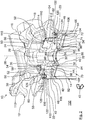
- a filter system 10 for engine oil of an internal combustion engine of a motor vehicle is shown in different perspectives, sections and detailed views.
- the filter system 10 comprises a filter head 12 to which a spin-on filter 14 is detachably attached.
- the filter head 12 is made of metal.
- the filter head 12 is firmly connected to the internal combustion engine and serves as a connection part for the spin-on filter 14.
- the filter head 12 comprises an inlet 16 and an outlet 18 for the engine oil.
- the inlet 16 and the outlet 18 are connected to corresponding oil lines of the internal combustion engine in a manner which is not of further interest here.
- the filter head 12 has a head-side connecting part 20 of a releasable connecting device, denoted as a whole by 22, for connecting the spin-on filter 14 to the filter head 12.
- the head-side connecting part 20 is made of metal.
- the side of the head-side connecting part 20 facing the spin-on filter 14 has the shape and function of a connecting piece.
- the head-side connecting part 20 is screwed into a hollow connecting cylinder 24, which is connected in one piece to the filter head 12.
- the connecting cylinder 24 has an internal thread.
- the connection cylinder 24 is coaxial with a filter axis 26.
- the head-side connecting part 20 can also be connected to the filter head 12 in one piece instead of being screwed onto the filter head 12 as a separate component.
- the head-side connecting part 20 has a cylindrical connecting sleeve section 28 with an external thread matching the internal thread of the connecting cylinder 24.
- the connecting sleeve section 28 is also coaxial with the filter axis 26.
- the connecting sleeve section 28 is connected to the outlet 18 of the filter head 12.
- the connecting sleeve section 28 is simply stepped on its radially inner circumferential side.
- the inner cross-section of the connecting sleeve section 28 on the enlarged side facing the spin-on filter 14 is approximately hexagonal. The corners are slightly rounded.
- the inner cross section of an imaginary inscribed circle on the side of the outlet 18 is smaller than the inner cross section of the connecting sleeve section 28 on the side facing the spin-on filter 14.
- connection cylinder 24 is surrounded radially on the outside by an inlet annular space 30 of the filter head 12.
- An end face of the connecting sleeve section 28 facing the spin-on filter 14 forms an annular coaxial sealing surface 32.
- the connecting sleeve section 28 of the head-side connecting part 20 is surrounded radially on the outside by an outer cylinder section 34.
- the peripheral wall of the outer cylinder section 34 has approximately the shape of a hollow circular cylinder.
- the outer cylinder section 34 is coaxial with the filter axis 26. It extends in the axial direction approximately from the axial center plane of the connection sleeve section 28 in the direction of the end face of the connection sleeve section 28 facing the spin-on filter 14.
- the outer cylinder section 34 On its side facing the filter head 12, the outer cylinder section 34 is connected in one piece to the radially outer circumferential side of the connecting sleeve section 28 via a radial annular disk section 36.
- a plurality of radial connecting walls 40 are arranged in an annular space 38 between the radially inner circumferential side of the outer cylinder section 34 and the radially outer circumferential side of the connecting sleeve section 28.
- the radial connection walls 40 are each connected in one piece radially on the outside with the outer cylinder section 34, on the radial inside with the connecting sleeve section 28 and with an underside of the radial annular disk section 36.
- the radial connecting walls 40 extend radially and axially, respectively. When viewed in the direction of the filter axis 26, they are arranged approximately in a star shape.
- a total of three head-side ramp sections 42 are arranged on the radially outer circumferential side of the outer cylinder section 34.
- the head-side ramp sections 42 are identical with regard to their dimensions and shape.
- the head-side ramp sections 42 each run helically with respect to the filter axis 26.
- a slope direction of the head-side ramp sections 42 corresponds to a known right-hand thread.
- a closing direction of rotation 43 of the spin-on filter 14 relative to the filter head 12, which in the Figures 1 , 2 , 4th and 6th is indicated by an arrow, for closing the connecting device 22 corresponds to that of a known right-hand thread.
- the closing direction of rotation 43 runs from the spin-on filter 14 to the filter head 12, viewed in the axial direction, clockwise.
- the head-side ramp sections 42 each extend approximately over a circumferential angle of 240 °.
- the head-side ramp sections 42 are arranged offset from one another. In each case two of the head-side ramp sections 42 overlap each other over half of their circumferential dimensions.
- the beginnings of the head-side ramp sections 42 are each located on the free end face of the outer cylinder section 34 facing the spin-on filter 14.
- Each head-side ramp section 42 viewed circumferentially, consists of two areas.
- a first area with a respective insertion ramp surface 44 extends circumferentially from the start of a respective head-side ramp section 42 to the start of the next head-side ramp section 42 viewed against the closing direction of rotation 43.
- the insertion ramp surfaces 44 are free in the axial direction when viewed from the spin-on filter 14 accessible. They each extend in the radial direction and helically in the circumferential direction.
- the insertion ramp surfaces 44 each extend in the radial direction over the entire radial wall thickness of the outer cylinder section 34.
- a region with a groove ramp surface 46 adjoins the respective insertion ramp surface 44.
- the circumferential extension of the insertion ramp surface 44 corresponds to the circumferential extension of the groove ramp surfaces 46. They each extend over a circumferential angle of 120 °.
- the grooved ramp surfaces 46 are located radially on the outside of the outer cylinder section 34. The areas with the grooved ramp surfaces 46 each overlap with the following head-side ramp sections 42 viewed opposite to the closing direction of rotation 43 Lead-in ramp surface 44 of the following head-side ramp section 42.
- the groove ramp surfaces 46 extend in the radial direction over approximately half the radial wall thickness of the outer cylinder section 34.
- the insertion ramp surfaces 44 merge steplessly into the groove ramp surfaces 46.
- the groove ramp surfaces 46 have the same slope as the insertion ramp surfaces 44.
- the groove ramp surfaces 46 each begin in the circumferential direction at the level of the beginning of the respectively following head-side ramp section 42 in a clockwise direction.
- the groove ramp surfaces 46 end at the level of the start of the circumferentially next but one head-side ramp section 42.
- the groove ramp surfaces 46 delimit a respective ramp groove 48 on one axial side.
- the ramp grooves 48 are each delimited by a head-side retaining surface 49, axially opposite the insertion ramp surface 42, of the corresponding region of the subsequent head-side ramp section 42.
- the ramp grooves 48 have a constant axial extent in the circumferential direction. Their radial extent is also constant when viewed in the circumferential direction.
- the latching elements 50 are each connected in one piece to the outer cylinder section 34.
- the locking elements 50 are radial elevations.
- the locking elements 50 are arranged in the axial direction approximately at the level of the radial annular disk section 36.
- the locking elements 50 are each approximately wedge-like. In a rear region with respect to the closing direction of rotation 43 of the connecting device 22, each latching element 50 has a rising guide surface 54.
- the guide surface 54 is located on the radially outer circumferential side of the latching elements 50.
- a latching recess 56 adjoins in each case.
- the radial extent of the locking elements 50 in the area of the locking recess 54 is smaller than in the area of the end of the guide surface 54 raised in the radial direction.
- Each locking element 50 extends circumferentially over a circumferential angle of approximately 25 ° to 30 °.
- the transition from the guide surface 54 to the corresponding latching recess 56 is located circumferentially approximately at the same level as the end of one of the head-side ramp sections 42 and the beginning of the next but one head-side ramp section 42, viewed counter to the closing direction of rotation 43.
- the connecting cylinder 24 and the head-side connecting part 20 are surrounded by a coaxial circular-cylindrical outer sealing section 58.
- the free end face of the outer sealing section 58 faces the spin-on filter 14. Its internal cross-section increases towards its free end face.
- the radially inner circumferential side of the outer sealing section 58 forms an outer sealing surface 60.
- the filter bowl 12 has an outer collar 62, which extends in sections coaxially to the filter axis 26 and partially surrounds the outer sealing section 58 radially on the outside.
- the spin-on filter 14 has a round cross section. It is essentially coaxial to the filter axis 26.
- the spin-on filter 14 has a filter bowl 64, in the open side of which a filter cover 66 is fastened.
- the filter bowl 64 has an outwardly curved filter base 68.
- a coaxial filter element 70 is arranged in the filter bowl 64.
- the filter element 70 has a circumferentially closed filter medium 72 which is folded in a zigzag shape Figure 1 above, and a counter end plate 76, below, connected.
- connection end disk 74 is shown in detail in FIGS Figures 2 , 5 and 6 shown. It is located on the side of the filter element 70 facing the filter cover 66.
- the filter medium 72 surrounds an element interior 78 of the filter element 70.
- the element interior 78 is located on a clean side of the filter element 70.
- the counter end disk 76 closes the element interior 78 on the end face of the filter element 70 facing the filter base 68.
- a plurality of spring elements 80 are supported on the outside of the counter end disk 76 facing the filter base 78.
- the filter element 70 is surrounded radially on the outside by a raw-side annular space 82 which is delimited by the radially inner circumferential side of the filter bowl 64.
- a coaxial central tube 84 extends in the element interior 78 between the counter end disk 76 and the connecting end disk 74.
- a peripheral wall of the central tube 84 is permeable to the engine oil.
- a radially inner circumferential side, namely radially inner folded edges, of the filter medium 72 is supported on the radially outer circumferential side of the central tube 84.
- the connecting end plate 74 has a coaxial outlet opening 86 for the filtered engine oil.
- the outlet opening 86 forms a central oil drainage channel.
- a coaxial seal receiving cylinder 88 is arranged in one piece on the axially outer side of the connecting end disk 74.
- a radially inner peripheral side of the seal receiving cylinder 88 is stepped.
- the seal receiving cylinder 88 On its end face facing away from the element interior 78, the seal receiving cylinder 88 has a coaxial sealing groove 90 with an annular inner seal 92.
- the inner seal 92 is arranged axially offset with respect to the filter-side connecting part 108 towards the interior of the spin-on filter 14.
- the inner seal 92 is designed as a flat seal.
- the inner seal 92 has a sealing surface 93 running around the outlet opening 86.
- the inner seal 92 lies with its side facing away from the element interior 78 tightly against the sealing surface 32 of the connecting sleeve section 28 of the head-side connecting part 20.
- the inner seal 92 acts in the axial direction.
- the inner seal 92 separates a raw side of the filter element 70, radially outside of the seal receiving cylinder 88, tightly from a clean side, radially inside the seal receiving cylinder 88.
- the smallest inner radius of the seal receiving cylinder 88 corresponds approximately to the inner radius of an imaginary inscribed circle of the connecting sleeve section 28 on its side with enlarged cross-section.
- the seal receiving cylinder 88 is supported radially on the outside with support elements 94 against the radially extending section of the connecting end disk 74.
- the support elements 94 each extend radially and axially.
- inner support elements 96 are also provided, which support an annular section of the seal receiving cylinder 88 which surrounds the sealing groove 90 radially on the inside.
- the filter cover 66 has the shape of a ring with an approximately rectangular profile.
- the filter cover 66 is made of metal.
- the filter cover 66 has the function of a connection plate for connecting the spin-on filter 14 to the filter head 12.
- the filter cover 66 has a receiving opening 98 coaxial to the filter axis 26 for receiving the outer cylinder section 34 of the head-side connecting part 20 within the radially outer edge of the filter cover 66, a coaxial annular groove 100 is arranged on the outside facing away from the filter base 68 for receiving a cover sheet metal ring 102.
- a plurality of continuous inlet channels 104 are arranged radially between the annular groove 100 and the receiving opening 98.
- the inlet channels 104 each extend parallel to the filter axis 46. They connect the inlet annular space 30 of the filter head 12 with the interior of the filter bowl 64, or the raw-side annular space 82.
- filter-side ramp sections 106 are arranged on the radially inner circumferential side of the filter cover 66.
- the ramp sections 106 each realize connecting webs.
- the filter-side ramp sections 106 each extend radially inward from the radially inner circumferential side of the filter cover 66.
- the filter-side ramp sections 106 are essentially identical in their extension and their circumferential course.
- the sides of the filter-side ramp sections 106 facing the interior of the filter bowl 64 each form filter-side holding surfaces 107.
- the sides of the filter-side ramp sections 106 facing away from the interior of the filter bowl 64 each form filter-side feed ramps 109.
- the filter-side holding surfaces 107 and the feed ramps 109 run approximately parallel to one another.
- the filter-side ramp sections 106 each extend, analogously to the head-side ramp sections 42, helically with respect to the filter axis 26. Their slopes correspond to those of the head-side ramp sections 42.
- the filter-side ramp sections 106 each extend with respect to the filter axis 26 over a circumferential angle of 120 °.
- the filter-side ramp sections 106 do not overlap.
- the beginnings 111 of the filter-side ramp section 106 are located on the axial side facing away from the interior of the filter bowl 64. When the spin-on filter 14 is installed, the beginnings 111 face the filter head 12.
- the beginnings 111 are spaced apart from a radially inner edge of the filter cover 66 facing away from the element interior 78, on the head side and surrounding the outlet opening 86.
- each filter-side ramp section 106 is at the same level as the end of the filter-side ramp section 106 preceding in the closing direction of rotation 43.
- the axial heights of the filter-side ramp sections 106 are circumferentially constant. They correspond to the axial heights of the ramp grooves 48 of the head-side ramp sections 42.
- the filter-side ramp sections 106 and the receiving opening 98 together form a filter-side connecting part 108 of the connecting device 22.
- the sealing surface 93 of the inner seal 92 is axially offset with respect to the filter-side connecting part 108 towards the filter element 70 .
- the latching spring elements 110 are parts of the locking device 52.
- the latching spring elements 110 each have a holding section 112.
- the holding section 112 is radially connected in one piece to the filter cover 66 between the annular groove 100 and the receiving opening 98.
- a respective spring arm section 114 of the detent spring elements 110 is connected in one piece to the holding section 112.
- the spring arm sections 114 are each located on the front side of the holding sections 112 when viewed in the direction of rotation 43.
- the spring arm sections 114 each extend circumferentially over a circumferential angle of approximately 30 °.
- the spring arm sections 114 can be resiliently bent outward in the radial direction at the holding sections 112. At their free ends facing away from the holding sections 112, the spring arm sections 114 each merge into a latching lug 116.
- the locking lugs 116 extend radially inward.
- the latching lug 116 is located on the same circumferential side as a beginning 111 of one of the filter-side latching sections 106 and an end of the respective previous filter-side ramp section 106.
- the sheet metal cover ring 102 has a profile that is bent several times. With its radially outer circumferential side, it is firmly connected to a free edge of the filter bowl 64 by means of a flanged connection 120. Radially within the crimped connection 120, the sheet metal cover ring 102 has an approximately right-angled, circumferentially closed first bending section. In the area of the first bending section, the sheet metal cover ring 102 forms, on its side facing the filter cover 66, a collar 122 which engages in the annular groove 100 of the filter cover 66.
- the collar 122 realizes a receiving groove 124 for the outer sealing section 58 of the filter head 12.
- the radially inner circumferential side of the sheet metal cover ring 102 is bent into a U-shaped profile, the opening of which points radially outward.
- the U-shaped profile contains a coaxial, circumferentially closed sealing groove 126.
- An outer seal 128 is arranged in the sealing groove 126.
- the outer seal 128 is an O-ring seal.
- the outer seal 128 is oriented radially outward with respect to the filter axis 26.
- the outer seal 128 acts in the radial direction.
- the cover sheet metal ring 102 On its inner edge axially facing away from the filter cover 66, the cover sheet metal ring 102 has a plurality of notches 130 distributed around the circumference.
- the outer seal 128 lies tightly against the outer sealing surface 60 of the outer sealing section 58.
- the outer seal 128 separates the raw side of the filter element 70, or the inlet annular space 30, from the surroundings 132.
- the spin-on filter 14, with the filter cover 66 in front is moved axially to a connection axis, which in the exemplary embodiment coincides with the filter axis 26, in a plugging movement towards the head-side connection part 20 of the filter head 12.
- the outer cylinder section 34 is inserted into the receiving opening 98 of the filter cover 66 until the filter-side ramp sections 106 axially abut the insertion ramp surfaces 44 of the head-side ramp sections 42.
- the outer seal portion 58 is axially remote from the outer seal 128.
- the filter-side connecting part 108 With a rotary movement of the interchangeable cylinder 14 in the closing direction of rotation 43, the filter-side connecting part 108 is screwed into the head-side connecting part 20.
- the filter-side ramp sections 106 each engage in one of the ramp grooves 48. After an angle of rotation of 60 ° from the beginning of the immersion of the filter-side ramp sections 106 into the ramp grooves 48, the outer seal 128 begins to rest against the outer sealing surface 60 of the outer sealing section 58 and is guided in the enlarged cross-section when the spin-on filter 14 continues to rotate.
- the inner seal 92 lies tightly and compressed in the axial direction against the sealing surface 32 of the connecting sleeve section 28.
- the latching lugs 116 of the spring arm sections 114 of the latching spring elements 110 each abut the rear ends of the guide surfaces 54 of the latching elements 50 in the direction of rotation 43 for closing.
- the latching lugs 116 are guided on the guide surfaces 54.
- the latching lugs 116 each latch into the latching depressions 56 of the latching elements 50.
- a perceptible noise is generated.
- the latched lugs 116 make it more difficult to open the connecting device 22 by rotating the interchangeable cylinder 14 counter to the closing direction of rotation 43. Furthermore, the compressed inner seal 92 makes it more difficult to open the connecting device 22 due to the friction.
- the spin-on filter 14 is removed from the filter head 12 by turning the spin-on filter 14 against the direction of rotation 43.
- the spring force of the spring sections 114 and the frictional force between the inner seal 92 and the sealing surface 32 must first be overcome.
- engine oil to be filtered is supplied to the inlet annular space 30 through the inlet 16 of the filter head 12. From there, the engine oil passes through the inlet channels 104 into the raw-side annular space 82 of the spin-on filter 14.
- the engine oil to be filtered flows through the filter medium 72 from radially outside to radially inside and is cleaned.
- the cleaned engine oil leaves the element interior 78 through the outlet opening 86 and enters the interior of the connecting sleeve section 28, which serves as a fluid connector with an oil channel.
- the interior of the connecting sleeve section 28 thus communicates fluidly with the outlet opening 86. From there, the cleaned engine oil flows into the outlet 18 of the filter head 12 and leaves the filter system 10.
- inlet channels can be provided on the filter head 20 and in particular on the annular disk section 36 of the connecting sleeve section 28, so that the raw fluid can flow into the filter alternatively or in addition to the inlet via the inlet channels 104 through head-side inlet channels.
Landscapes
- Chemical & Material Sciences (AREA)
- Engineering & Computer Science (AREA)
- Chemical Kinetics & Catalysis (AREA)
- Combustion & Propulsion (AREA)
- Mechanical Engineering (AREA)
- General Engineering & Computer Science (AREA)
- Lubrication Details And Ventilation Of Internal Combustion Engines (AREA)
Applications Claiming Priority (2)
| Application Number | Priority Date | Filing Date | Title |
|---|---|---|---|
| DE102013011619.8A DE102013011619A1 (de) | 2013-07-12 | 2013-07-12 | Spin-On Filter für eine Filtervorrichtung für Fluid, Filtervorrichtung und Filterkopf einer Filtervorrichtung |
| PCT/EP2014/064532 WO2015004100A1 (de) | 2013-07-12 | 2014-07-08 | Spin-on filter für eine filtervorrichtung für fluid, filtervorrichtung und filterkopf einer filtervorrichtung |
Publications (2)
| Publication Number | Publication Date |
|---|---|
| EP3019264A1 EP3019264A1 (de) | 2016-05-18 |
| EP3019264B1 true EP3019264B1 (de) | 2021-09-01 |
Family
ID=51162799
Family Applications (1)
| Application Number | Title | Priority Date | Filing Date |
|---|---|---|---|
| EP14736795.7A Active EP3019264B1 (de) | 2013-07-12 | 2014-07-08 | Spin-on filter für eine filtervorrichtung für fluid, filtervorrichtung und filterkopf einer filtervorrichtung |
Country Status (5)
| Country | Link |
|---|---|
| US (1) | US10561967B2 (zh) |
| EP (1) | EP3019264B1 (zh) |
| CN (1) | CN105517684B (zh) |
| DE (1) | DE102013011619A1 (zh) |
| WO (1) | WO2015004100A1 (zh) |
Families Citing this family (14)
| Publication number | Priority date | Publication date | Assignee | Title |
|---|---|---|---|---|
| DE102015000069B4 (de) * | 2014-01-23 | 2023-06-15 | Mann+Hummel Gmbh | Wechselfilter einer Filtervorrichtung und Filtervorrichtung |
| CN104696125A (zh) * | 2015-02-27 | 2015-06-10 | 蚌埠市风驰滤清器有限公司 | 一种高效柴油滤清器 |
| DE102016009488A1 (de) | 2015-08-06 | 2017-02-09 | Mann + Hummel Gmbh | Spin-On-Filter und Filterkopf für eine Filtervorrichtung, sowie Filtervorrichtung zum Filtern eines Fluids |
| US10493385B2 (en) | 2017-01-10 | 2019-12-03 | MANN+HUMMEL Filtration Technology Group Inc. | J-hook filter assembly |
| GB201701105D0 (en) | 2017-01-23 | 2017-03-08 | Parker Hannifin Mfg (Uk) Ltd | A filter element |
| DE102017011437A1 (de) * | 2017-02-14 | 2018-08-16 | Mann+Hummel Gmbh | Filter einer Filtervorrichtung zur Filtrierung von Fluid und Filterkopf einer Filtervorrichtung |
| DE202017104365U1 (de) * | 2017-06-01 | 2018-09-04 | Hans Sasserath Gmbh & Co. Kg | Druckminderer-Filter-Anordnung |
| CN107485902B (zh) * | 2017-09-30 | 2023-04-14 | 北京碧水源净水科技有限公司 | 一种旋转滤芯结构 |
| US20200088145A1 (en) * | 2018-09-17 | 2020-03-19 | GM Global Technology Operations LLC | Fuel strainer |
| CN113286644B (zh) * | 2019-01-11 | 2022-11-15 | 康明斯滤清系统知识产权公司 | 用于过滤器的多螺纹连接器 |
| EP3972711A4 (en) * | 2019-05-20 | 2023-01-18 | Cummins Filtration IP, Inc. | GRADIENT SEALING INTERFACE FILTRATION ELEMENT |
| EP4051406A1 (en) * | 2019-10-30 | 2022-09-07 | Donaldson Company, Inc. | Filter arrangements for liquids and methods of use |
| DE102019135091B4 (de) * | 2019-12-19 | 2024-03-14 | Mann+Hummel Gmbh | Behandlungsvorrichtung zur Behandlung von insbesondere flüssigen Fluiden sowie Anschlusskopf einer Behandlungsvorrichtung |
| CN111561411A (zh) * | 2020-05-27 | 2020-08-21 | 平原滤清器有限公司 | 具有偏心加热结构的燃油滤清器 |
Family Cites Families (24)
| Publication number | Priority date | Publication date | Assignee | Title |
|---|---|---|---|---|
| US2983533A (en) * | 1957-01-22 | 1961-05-09 | A P D Co | Sealing ring |
| US3325015A (en) | 1964-07-20 | 1967-06-13 | Walker Mfg Co | Filter seal |
| US4832844A (en) | 1986-06-05 | 1989-05-23 | Ayers William R | Seal for a spin-on filter |
| JP2859475B2 (ja) * | 1991-10-07 | 1999-02-17 | 和興産業株式会社 | スピンオンフィルターおよびそのフィルター用エレメント組立体 |
| US6023834A (en) | 1992-06-29 | 2000-02-15 | Fleetwood, Inc. | Method for assembling an improved bead-lock high-pressure filter utilizing a stamped metal cover |
| AU8077294A (en) * | 1993-10-21 | 1995-05-08 | Tawas Industries | Oil and fuel filter canister and housing |
| DE4432529A1 (de) | 1994-09-13 | 1996-03-14 | Bosch Gmbh Robert | Wechselfilterelement zum Reinigen von Kraftstoff und Filtergehäuse zum Einbau des Wechselfilterelementes |
| GB9620002D0 (en) | 1996-09-21 | 1996-11-13 | Lucas Ind Plc | Filter assembly |
| DE10035555A1 (de) | 2000-07-21 | 2002-01-31 | Mann & Hummel Filter | Auswechselbare Filterpatrone mit Stützkörper bzw. Flüssigkeitsfilter mit eben dieser Filterpatrone |
| DE10052524A1 (de) | 2000-10-23 | 2002-04-25 | Beko Technologies Gmbh | Filter zum Abscheiden von Fremdstoffen aus einem Gasstrom |
| US20030019819A1 (en) | 2001-07-30 | 2003-01-30 | Karl Fritze | Hot disconnect replaceable water filter assembly |
| US7434697B2 (en) | 2004-02-16 | 2008-10-14 | Fleetguard Inc. | Disposable, spin-on filter |
| US8057669B2 (en) | 2005-02-22 | 2011-11-15 | Baldwin Filters, Inc. | Filter element and filter assembly including locking mechanism |
| FR2885534B1 (fr) | 2005-05-13 | 2007-07-27 | Filtrauto Sa | Cartouche filtrante et systeme de montage d'une telle cartouche |
| DE102006011842A1 (de) * | 2006-03-15 | 2007-09-20 | Hydac Filtertechnik Gmbh | Filterelement |
| DE102008004181A1 (de) * | 2007-01-12 | 2008-07-17 | Mann + Hummel Gmbh | Wechselfilter |
| DE202008004289U1 (de) * | 2008-03-27 | 2010-04-08 | Mann+Hummel Gmbh | Filterverschlusssystem mit Bajonett |
| DE102009035683A1 (de) * | 2009-07-30 | 2011-02-03 | Mann+Hummel Gmbh | Filter |
| JP5340867B2 (ja) * | 2009-09-18 | 2013-11-13 | 和興フィルタテクノロジー株式会社 | スピンオンフィルタおよびそのフィルタ用エレメント組立体 |
| US8869991B2 (en) | 2010-06-11 | 2014-10-28 | Wix Filtration Corp Llc | Spin-on filter assembly |
| DE102011009925A1 (de) * | 2011-01-31 | 2012-08-02 | Mann + Hummel Gmbh | Wechselfilter und Filterkopf eines Filters |
| US9308475B2 (en) * | 2011-04-12 | 2016-04-12 | Cummins Filtration Ip, Inc. | Filter apparatus with torque limiting mechanism |
| JP5663394B2 (ja) | 2011-05-06 | 2015-02-04 | 株式会社コガネイ | 調質機器の容器着脱装置 |
| EP2764901A1 (en) | 2013-02-07 | 2014-08-13 | Parker Hannifin Corporation | Keyed thread engagement on spin-on filter element |
-
2013
- 2013-07-12 DE DE102013011619.8A patent/DE102013011619A1/de not_active Ceased
-
2014
- 2014-07-08 WO PCT/EP2014/064532 patent/WO2015004100A1/de active Application Filing
- 2014-07-08 EP EP14736795.7A patent/EP3019264B1/de active Active
- 2014-07-08 CN CN201480050239.8A patent/CN105517684B/zh not_active Expired - Fee Related
-
2016
- 2016-01-06 US US14/989,256 patent/US10561967B2/en active Active
Also Published As
| Publication number | Publication date |
|---|---|
| CN105517684B (zh) | 2018-09-21 |
| EP3019264A1 (de) | 2016-05-18 |
| US20160144298A1 (en) | 2016-05-26 |
| US10561967B2 (en) | 2020-02-18 |
| DE102013011619A1 (de) | 2015-01-15 |
| WO2015004100A1 (de) | 2015-01-15 |
| CN105517684A (zh) | 2016-04-20 |
Similar Documents
| Publication | Publication Date | Title |
|---|---|---|
| EP3019264B1 (de) | Spin-on filter für eine filtervorrichtung für fluid, filtervorrichtung und filterkopf einer filtervorrichtung | |
| EP3228374B1 (de) | Wechselfilter einer behandlungsvorrichtung zur behandlung von insbesondere flüssigen fluiden und behandlungsvorrichtung | |
| EP0748646B1 (de) | Flüssigkeitsfilter | |
| EP3082997B1 (de) | Behandlungsvorrichtung zur behandlung von insbesondere flüssigen fluiden und behandlungselement einer behandlungsvorrichtung | |
| DE19502020C2 (de) | Flüssigkeitsfilter | |
| EP3019265B1 (de) | Spin-on filter für eine filtervorrichtung für fluid und filtervorrichtung | |
| DE29613703U1 (de) | Flüssigkeitsfilter, insbesondere für Öl oder Kraftstoff einer Brennkraftmaschine, und dazu passender maschinenseitiger Filteranschlußflansch | |
| EP3082998B1 (de) | Behandlungsvorrichtung zur behandlung von insbesondere flüssigen fluiden und behandlungselement einer behandlungsvorrichtung | |
| EP3221026B1 (de) | Filterelement mit überragendem bajonettvorsprung | |
| DE29610290U1 (de) | Flüssigkeitsfilter | |
| DE202007008483U1 (de) | Funktionselement zum Betätigen eines Ventils | |
| EP3019263B1 (de) | Spin-on filter für eine filtervorrichtung für fluid, filtervorrichtung und filterkopf einer filtervorrichtung | |
| EP3042710B1 (de) | Wechselfilter einer filtervorrichtung für fluid und filtervorrichtung | |
| WO2021009094A1 (de) | Fluidfilter für einen kraftwagen und filterkartusche für einen fluidfilter | |
| DE102013011620B4 (de) | Filtervorrichtung für Fluid und Wechselfilter | |
| DE102013011616B4 (de) | Filtervorrichtung für Fluid und Wechselfilter | |
| WO2015004114A2 (de) | Filtervorrichtung für fluid und wechselfilter | |
| DE102013011617B4 (de) | Filtervorrichtung für Fluid und Wechselfilter | |
| DE102019135091B4 (de) | Behandlungsvorrichtung zur Behandlung von insbesondere flüssigen Fluiden sowie Anschlusskopf einer Behandlungsvorrichtung | |
| DE102019135085B4 (de) | Behandlungsvorrichtung zur Behandlung von insbesondere flüssigen Fluiden sowie Anschlusskopf einer Behandlungsvorrichtung | |
| WO2021078780A1 (de) | Behandlungsvorrichtung zur behandlung von insbesondere flüssigen fluiden sowie behandlungseinheit und anschlusskopf einer behandlungsvorrichtung | |
| EP4171781A1 (de) | Filtereinrichtung mit einem filterelement |
Legal Events
| Date | Code | Title | Description |
|---|---|---|---|
| PUAI | Public reference made under article 153(3) epc to a published international application that has entered the european phase |
Free format text: ORIGINAL CODE: 0009012 |
|
| 17P | Request for examination filed |
Effective date: 20151216 |
|
| AK | Designated contracting states |
Kind code of ref document: A1 Designated state(s): AL AT BE BG CH CY CZ DE DK EE ES FI FR GB GR HR HU IE IS IT LI LT LU LV MC MK MT NL NO PL PT RO RS SE SI SK SM TR |
|
| AX | Request for extension of the european patent |
Extension state: BA ME |
|
| DAX | Request for extension of the european patent (deleted) | ||
| STAA | Information on the status of an ep patent application or granted ep patent |
Free format text: STATUS: EXAMINATION IS IN PROGRESS |
|
| 17Q | First examination report despatched |
Effective date: 20190508 |
|
| RAP1 | Party data changed (applicant data changed or rights of an application transferred) |
Owner name: MANN+HUMMEL GMBH |
|
| STAA | Information on the status of an ep patent application or granted ep patent |
Free format text: STATUS: EXAMINATION IS IN PROGRESS |
|
| GRAP | Despatch of communication of intention to grant a patent |
Free format text: ORIGINAL CODE: EPIDOSNIGR1 |
|
| STAA | Information on the status of an ep patent application or granted ep patent |
Free format text: STATUS: GRANT OF PATENT IS INTENDED |
|
| INTG | Intention to grant announced |
Effective date: 20210209 |
|
| RAP3 | Party data changed (applicant data changed or rights of an application transferred) |
Owner name: MANN+HUMMEL GMBH |
|
| GRAS | Grant fee paid |
Free format text: ORIGINAL CODE: EPIDOSNIGR3 |
|
| RIN1 | Information on inventor provided before grant (corrected) |
Inventor name: SANCAR, ERCAN Inventor name: JOKSCHAS, GUENTER |
|
| GRAA | (expected) grant |
Free format text: ORIGINAL CODE: 0009210 |
|
| STAA | Information on the status of an ep patent application or granted ep patent |
Free format text: STATUS: THE PATENT HAS BEEN GRANTED |
|
| AK | Designated contracting states |
Kind code of ref document: B1 Designated state(s): AL AT BE BG CH CY CZ DE DK EE ES FI FR GB GR HR HU IE IS IT LI LT LU LV MC MK MT NL NO PL PT RO RS SE SI SK SM TR |
|
| REG | Reference to a national code |
Ref country code: GB Ref legal event code: FG4D Free format text: NOT ENGLISH |
|
| REG | Reference to a national code |
Ref country code: CH Ref legal event code: EP Ref country code: AT Ref legal event code: REF Ref document number: 1425593 Country of ref document: AT Kind code of ref document: T Effective date: 20210915 |
|
| REG | Reference to a national code |
Ref country code: DE Ref legal event code: R096 Ref document number: 502014015850 Country of ref document: DE |
|
| REG | Reference to a national code |
Ref country code: IE Ref legal event code: FG4D Free format text: LANGUAGE OF EP DOCUMENT: GERMAN |
|
| REG | Reference to a national code |
Ref country code: LT Ref legal event code: MG9D |
|
| REG | Reference to a national code |
Ref country code: NL Ref legal event code: MP Effective date: 20210901 |
|
| PG25 | Lapsed in a contracting state [announced via postgrant information from national office to epo] |
Ref country code: HR Free format text: LAPSE BECAUSE OF FAILURE TO SUBMIT A TRANSLATION OF THE DESCRIPTION OR TO PAY THE FEE WITHIN THE PRESCRIBED TIME-LIMIT Effective date: 20210901 Ref country code: SE Free format text: LAPSE BECAUSE OF FAILURE TO SUBMIT A TRANSLATION OF THE DESCRIPTION OR TO PAY THE FEE WITHIN THE PRESCRIBED TIME-LIMIT Effective date: 20210901 Ref country code: RS Free format text: LAPSE BECAUSE OF FAILURE TO SUBMIT A TRANSLATION OF THE DESCRIPTION OR TO PAY THE FEE WITHIN THE PRESCRIBED TIME-LIMIT Effective date: 20210901 Ref country code: BG Free format text: LAPSE BECAUSE OF FAILURE TO SUBMIT A TRANSLATION OF THE DESCRIPTION OR TO PAY THE FEE WITHIN THE PRESCRIBED TIME-LIMIT Effective date: 20211201 Ref country code: LT Free format text: LAPSE BECAUSE OF FAILURE TO SUBMIT A TRANSLATION OF THE DESCRIPTION OR TO PAY THE FEE WITHIN THE PRESCRIBED TIME-LIMIT Effective date: 20210901 Ref country code: ES Free format text: LAPSE BECAUSE OF FAILURE TO SUBMIT A TRANSLATION OF THE DESCRIPTION OR TO PAY THE FEE WITHIN THE PRESCRIBED TIME-LIMIT Effective date: 20210901 Ref country code: FI Free format text: LAPSE BECAUSE OF FAILURE TO SUBMIT A TRANSLATION OF THE DESCRIPTION OR TO PAY THE FEE WITHIN THE PRESCRIBED TIME-LIMIT Effective date: 20210901 Ref country code: NO Free format text: LAPSE BECAUSE OF FAILURE TO SUBMIT A TRANSLATION OF THE DESCRIPTION OR TO PAY THE FEE WITHIN THE PRESCRIBED TIME-LIMIT Effective date: 20211201 |
|
| PG25 | Lapsed in a contracting state [announced via postgrant information from national office to epo] |
Ref country code: PL Free format text: LAPSE BECAUSE OF FAILURE TO SUBMIT A TRANSLATION OF THE DESCRIPTION OR TO PAY THE FEE WITHIN THE PRESCRIBED TIME-LIMIT Effective date: 20210901 Ref country code: LV Free format text: LAPSE BECAUSE OF FAILURE TO SUBMIT A TRANSLATION OF THE DESCRIPTION OR TO PAY THE FEE WITHIN THE PRESCRIBED TIME-LIMIT Effective date: 20210901 Ref country code: GR Free format text: LAPSE BECAUSE OF FAILURE TO SUBMIT A TRANSLATION OF THE DESCRIPTION OR TO PAY THE FEE WITHIN THE PRESCRIBED TIME-LIMIT Effective date: 20211202 |
|
| PG25 | Lapsed in a contracting state [announced via postgrant information from national office to epo] |
Ref country code: IS Free format text: LAPSE BECAUSE OF FAILURE TO SUBMIT A TRANSLATION OF THE DESCRIPTION OR TO PAY THE FEE WITHIN THE PRESCRIBED TIME-LIMIT Effective date: 20220101 Ref country code: SM Free format text: LAPSE BECAUSE OF FAILURE TO SUBMIT A TRANSLATION OF THE DESCRIPTION OR TO PAY THE FEE WITHIN THE PRESCRIBED TIME-LIMIT Effective date: 20210901 Ref country code: SK Free format text: LAPSE BECAUSE OF FAILURE TO SUBMIT A TRANSLATION OF THE DESCRIPTION OR TO PAY THE FEE WITHIN THE PRESCRIBED TIME-LIMIT Effective date: 20210901 Ref country code: RO Free format text: LAPSE BECAUSE OF FAILURE TO SUBMIT A TRANSLATION OF THE DESCRIPTION OR TO PAY THE FEE WITHIN THE PRESCRIBED TIME-LIMIT Effective date: 20210901 Ref country code: PT Free format text: LAPSE BECAUSE OF FAILURE TO SUBMIT A TRANSLATION OF THE DESCRIPTION OR TO PAY THE FEE WITHIN THE PRESCRIBED TIME-LIMIT Effective date: 20220103 Ref country code: NL Free format text: LAPSE BECAUSE OF FAILURE TO SUBMIT A TRANSLATION OF THE DESCRIPTION OR TO PAY THE FEE WITHIN THE PRESCRIBED TIME-LIMIT Effective date: 20210901 Ref country code: EE Free format text: LAPSE BECAUSE OF FAILURE TO SUBMIT A TRANSLATION OF THE DESCRIPTION OR TO PAY THE FEE WITHIN THE PRESCRIBED TIME-LIMIT Effective date: 20210901 Ref country code: CZ Free format text: LAPSE BECAUSE OF FAILURE TO SUBMIT A TRANSLATION OF THE DESCRIPTION OR TO PAY THE FEE WITHIN THE PRESCRIBED TIME-LIMIT Effective date: 20210901 Ref country code: AL Free format text: LAPSE BECAUSE OF FAILURE TO SUBMIT A TRANSLATION OF THE DESCRIPTION OR TO PAY THE FEE WITHIN THE PRESCRIBED TIME-LIMIT Effective date: 20210901 |
|
| REG | Reference to a national code |
Ref country code: DE Ref legal event code: R097 Ref document number: 502014015850 Country of ref document: DE |
|
| PLBE | No opposition filed within time limit |
Free format text: ORIGINAL CODE: 0009261 |
|
| STAA | Information on the status of an ep patent application or granted ep patent |
Free format text: STATUS: NO OPPOSITION FILED WITHIN TIME LIMIT |
|
| PG25 | Lapsed in a contracting state [announced via postgrant information from national office to epo] |
Ref country code: IT Free format text: LAPSE BECAUSE OF FAILURE TO SUBMIT A TRANSLATION OF THE DESCRIPTION OR TO PAY THE FEE WITHIN THE PRESCRIBED TIME-LIMIT Effective date: 20210901 Ref country code: DK Free format text: LAPSE BECAUSE OF FAILURE TO SUBMIT A TRANSLATION OF THE DESCRIPTION OR TO PAY THE FEE WITHIN THE PRESCRIBED TIME-LIMIT Effective date: 20210901 |
|
| 26N | No opposition filed |
Effective date: 20220602 |
|
| PG25 | Lapsed in a contracting state [announced via postgrant information from national office to epo] |
Ref country code: SI Free format text: LAPSE BECAUSE OF FAILURE TO SUBMIT A TRANSLATION OF THE DESCRIPTION OR TO PAY THE FEE WITHIN THE PRESCRIBED TIME-LIMIT Effective date: 20210901 |
|
| PG25 | Lapsed in a contracting state [announced via postgrant information from national office to epo] |
Ref country code: MC Free format text: LAPSE BECAUSE OF FAILURE TO SUBMIT A TRANSLATION OF THE DESCRIPTION OR TO PAY THE FEE WITHIN THE PRESCRIBED TIME-LIMIT Effective date: 20210901 |
|
| REG | Reference to a national code |
Ref country code: CH Ref legal event code: PL |
|
| GBPC | Gb: european patent ceased through non-payment of renewal fee |
Effective date: 20220708 |
|
| REG | Reference to a national code |
Ref country code: BE Ref legal event code: MM Effective date: 20220731 |
|
| PG25 | Lapsed in a contracting state [announced via postgrant information from national office to epo] |
Ref country code: LU Free format text: LAPSE BECAUSE OF NON-PAYMENT OF DUE FEES Effective date: 20220708 Ref country code: LI Free format text: LAPSE BECAUSE OF NON-PAYMENT OF DUE FEES Effective date: 20220731 Ref country code: FR Free format text: LAPSE BECAUSE OF NON-PAYMENT OF DUE FEES Effective date: 20220731 Ref country code: CH Free format text: LAPSE BECAUSE OF NON-PAYMENT OF DUE FEES Effective date: 20220731 |
|
| PG25 | Lapsed in a contracting state [announced via postgrant information from national office to epo] |
Ref country code: GB Free format text: LAPSE BECAUSE OF NON-PAYMENT OF DUE FEES Effective date: 20220708 Ref country code: BE Free format text: LAPSE BECAUSE OF NON-PAYMENT OF DUE FEES Effective date: 20220731 |
|
| PG25 | Lapsed in a contracting state [announced via postgrant information from national office to epo] |
Ref country code: IE Free format text: LAPSE BECAUSE OF NON-PAYMENT OF DUE FEES Effective date: 20220708 |
|
| REG | Reference to a national code |
Ref country code: AT Ref legal event code: MM01 Ref document number: 1425593 Country of ref document: AT Kind code of ref document: T Effective date: 20220708 |
|
| PG25 | Lapsed in a contracting state [announced via postgrant information from national office to epo] |
Ref country code: AT Free format text: LAPSE BECAUSE OF NON-PAYMENT OF DUE FEES Effective date: 20220708 |
|
| PGFP | Annual fee paid to national office [announced via postgrant information from national office to epo] |
Ref country code: DE Payment date: 20230719 Year of fee payment: 10 |
|
| PG25 | Lapsed in a contracting state [announced via postgrant information from national office to epo] |
Ref country code: HU Free format text: LAPSE BECAUSE OF FAILURE TO SUBMIT A TRANSLATION OF THE DESCRIPTION OR TO PAY THE FEE WITHIN THE PRESCRIBED TIME-LIMIT; INVALID AB INITIO Effective date: 20140708 |
|
| PG25 | Lapsed in a contracting state [announced via postgrant information from national office to epo] |
Ref country code: MK Free format text: LAPSE BECAUSE OF FAILURE TO SUBMIT A TRANSLATION OF THE DESCRIPTION OR TO PAY THE FEE WITHIN THE PRESCRIBED TIME-LIMIT Effective date: 20210901 Ref country code: CY Free format text: LAPSE BECAUSE OF FAILURE TO SUBMIT A TRANSLATION OF THE DESCRIPTION OR TO PAY THE FEE WITHIN THE PRESCRIBED TIME-LIMIT Effective date: 20210901 |
|
| PG25 | Lapsed in a contracting state [announced via postgrant information from national office to epo] |
Ref country code: TR Free format text: LAPSE BECAUSE OF FAILURE TO SUBMIT A TRANSLATION OF THE DESCRIPTION OR TO PAY THE FEE WITHIN THE PRESCRIBED TIME-LIMIT Effective date: 20210901 |