EP3019134B1 - Tabletop sections for surgical tables - Google Patents
Tabletop sections for surgical tables Download PDFInfo
- Publication number
- EP3019134B1 EP3019134B1 EP14738793.0A EP14738793A EP3019134B1 EP 3019134 B1 EP3019134 B1 EP 3019134B1 EP 14738793 A EP14738793 A EP 14738793A EP 3019134 B1 EP3019134 B1 EP 3019134B1
- Authority
- EP
- European Patent Office
- Prior art keywords
- lock pin
- tabletop
- tabletop section
- hook
- switch
- Prior art date
- Legal status (The legal status is an assumption and is not a legal conclusion. Google has not performed a legal analysis and makes no representation as to the accuracy of the status listed.)
- Active
Links
Images


Classifications
-
- A—HUMAN NECESSITIES
- A61—MEDICAL OR VETERINARY SCIENCE; HYGIENE
- A61G—TRANSPORT, PERSONAL CONVEYANCES, OR ACCOMMODATION SPECIALLY ADAPTED FOR PATIENTS OR DISABLED PERSONS; OPERATING TABLES OR CHAIRS; CHAIRS FOR DENTISTRY; FUNERAL DEVICES
- A61G13/00—Operating tables; Auxiliary appliances therefor
- A61G13/10—Parts, details or accessories
- A61G13/12—Rests specially adapted therefor; Arrangements of patient-supporting surfaces
- A61G13/128—Rests specially adapted therefor; Arrangements of patient-supporting surfaces with mechanical surface adaptations
- A61G13/129—Rests specially adapted therefor; Arrangements of patient-supporting surfaces with mechanical surface adaptations having surface parts for adaptation of the size, e.g. for extension or reduction
-
- A—HUMAN NECESSITIES
- A61—MEDICAL OR VETERINARY SCIENCE; HYGIENE
- A61G—TRANSPORT, PERSONAL CONVEYANCES, OR ACCOMMODATION SPECIALLY ADAPTED FOR PATIENTS OR DISABLED PERSONS; OPERATING TABLES OR CHAIRS; CHAIRS FOR DENTISTRY; FUNERAL DEVICES
- A61G13/00—Operating tables; Auxiliary appliances therefor
- A61G13/02—Adjustable operating tables; Controls therefor
- A61G13/08—Adjustable operating tables; Controls therefor the table being divided into different adjustable sections
-
- A—HUMAN NECESSITIES
- A61—MEDICAL OR VETERINARY SCIENCE; HYGIENE
- A61G—TRANSPORT, PERSONAL CONVEYANCES, OR ACCOMMODATION SPECIALLY ADAPTED FOR PATIENTS OR DISABLED PERSONS; OPERATING TABLES OR CHAIRS; CHAIRS FOR DENTISTRY; FUNERAL DEVICES
- A61G13/00—Operating tables; Auxiliary appliances therefor
- A61G13/10—Parts, details or accessories
- A61G13/12—Rests specially adapted therefor; Arrangements of patient-supporting surfaces
- A61G13/128—Rests specially adapted therefor; Arrangements of patient-supporting surfaces with mechanical surface adaptations
- A61G13/1285—Rests specially adapted therefor; Arrangements of patient-supporting surfaces with mechanical surface adaptations having modular surface parts, e.g. being replaceable or turnable
-
- A—HUMAN NECESSITIES
- A61—MEDICAL OR VETERINARY SCIENCE; HYGIENE
- A61G—TRANSPORT, PERSONAL CONVEYANCES, OR ACCOMMODATION SPECIALLY ADAPTED FOR PATIENTS OR DISABLED PERSONS; OPERATING TABLES OR CHAIRS; CHAIRS FOR DENTISTRY; FUNERAL DEVICES
- A61G13/00—Operating tables; Auxiliary appliances therefor
- A61G13/10—Parts, details or accessories
- A61G13/101—Clamping means for connecting accessories to the operating table
-
- A—HUMAN NECESSITIES
- A61—MEDICAL OR VETERINARY SCIENCE; HYGIENE
- A61G—TRANSPORT, PERSONAL CONVEYANCES, OR ACCOMMODATION SPECIALLY ADAPTED FOR PATIENTS OR DISABLED PERSONS; OPERATING TABLES OR CHAIRS; CHAIRS FOR DENTISTRY; FUNERAL DEVICES
- A61G2203/00—General characteristics of devices
- A61G2203/70—General characteristics of devices with special adaptations, e.g. for safety or comfort
- A61G2203/78—General characteristics of devices with special adaptations, e.g. for safety or comfort for clamping
-
- A—HUMAN NECESSITIES
- A61—MEDICAL OR VETERINARY SCIENCE; HYGIENE
- A61G—TRANSPORT, PERSONAL CONVEYANCES, OR ACCOMMODATION SPECIALLY ADAPTED FOR PATIENTS OR DISABLED PERSONS; OPERATING TABLES OR CHAIRS; CHAIRS FOR DENTISTRY; FUNERAL DEVICES
- A61G7/00—Beds specially adapted for nursing; Devices for lifting patients or disabled persons
- A61G7/002—Beds specially adapted for nursing; Devices for lifting patients or disabled persons having adjustable mattress frame
- A61G7/015—Beds specially adapted for nursing; Devices for lifting patients or disabled persons having adjustable mattress frame divided into different adjustable sections, e.g. for Gatch position
Definitions
- the present invention relates to surgical tables and to tabletop sections therefor.
- Surgical tables, or operating tables comprising a base for standing on a floor, a column extending from the base, and a tabletop providing a patient support surface are well known.
- tabletop In order for surgical tables to be versatile, it is necessary for the tabletop to be disposable in a variety of different configurations. It is known to provide a surgical table with a tabletop that is divided into multiple separate tabletop sections, which are detachable from the table to enable replacement of one or more of the tabletop sections with a different form of tabletop section. Accordingly, different combinations of tabletop sections can be provided to vary the profile of the patient support surface, in order to best support a patient's body for surgery thereon or examination thereof.
- US-A-2007/136947 discloses a tabletop section comprising a hook around a space, the hook defining an opening into the space, and a plunger to push a rail against the inner surface of the hook.
- US-A-2006/242765 discloses a hook portion around a space, the hook defining an opening into the space, and a latch that rotates about dowel pins.
- a first aspect of the present invention provides a combination of a first tabletop section for a surgical table, the first tabletop section comprising a first connector for connecting the first tabletop section to a second tabletop section, the first connector having a hook disposed around a space and defining an opening into the space, and a lock pin for locking the connector to the second tabletop section, the lock pin being movable relative to the hook to change a degree to which the lock pin blocks the opening, characterised in that the lock pin is movable linearly relative to the hook to change the degree to which the lock pin blocks the opening, wherein the second tabletop section comprises a peg, and wherein the space is for receiving the peg of the second tabletop section.
- the hook lies in a first plane and the opening is in the first plane.
- the tabletop section comprises first and second ends extending substantially parallel to a first direction, and first and second sides connecting the first and second ends, each of the first and second sides extending substantially parallel to a second direction perpendicular to the first direction, wherein the first connector is at the first end.
- the first and second sides comprise respective first and second handle portions.
- the first direction is normal to the first plane.
- the lock pin is movable in the first plane relative to the hook to change the degree to which the lock pin blocks the opening.
- the lock pin is restricted to movement in the first plane relative to the hook to change the degree to which the lock pin blocks the opening.
- the lock pin is movable in a direction parallel to the second direction relative to the hook to change the degree to which the lock pin blocks the opening.
- the tabletop section comprises a switch for moving the lock pin relative to the hook to change the degree to which the lock pin blocks the opening.
- the switch is movable in a direction having at least a component parallel to a third direction perpendicular to each of the first and second directions for moving the lock pin relative to the hook to change the degree to which the lock pin blocks the opening.
- the switch is movable one of linearly and rotationally. Still further optionally, the switch is movable only one of linearly and rotationally.
- first and second handle portions comprise first and second walls defining respective first and second recesses in the first and second sides.
- the switch is movably located within a hole in the first wall.
- the switch is movable relative to the first wall between a first position and a second position, wherein when the switch is at the first position a greater degree of the switch is disposed in the first recess than when the switch is at the second position. Further optionally, the switch is biased towards the first position.
- the lock pin is movable relative to the hook between a first position and a second position, wherein when the lock pin is at the first position the lock pin blocks the opening to a greater degree than when the lock pin is at the second position. Further optionally, the lock pin is biased towards the first position.
- movement of the switch from the first position to the second position causes movement of the lock pin from the first position to the second position.
- the tabletop section comprises a second connector for connecting the tabletop section to the second tabletop section, the second connector having a second hook disposed around a second space and defining a second opening into the second space, and a second lock pin movable relative to the second hook to change a degree to which the second lock pin blocks the second opening, wherein the second connector is spaced from the first connector.
- the second hook lies in a second plane and the second opening is in the second plane.
- the second plane is parallel to and spaced from the first plane.
- a second aspect of the present invention provides a surgical table comprising a tabletop section according to the first aspect of the present invention.
- a tabletop section 100 connected to a second tabletop section 200.
- the first and second tabletop sections 100, 200 are respective sections of a tabletop 10 of a surgical table 1, which tabletop 10 provides a patient support surface 12.
- Each of the first and second tabletop sections 100, 200 provides a portion of the patient support surface 12 and, although not shown in the Figures for clarity, would have a respective separate mattress upon which a patient may lie.
- the second tabletop section 200 is usable to support a portion of the torso of a patient
- the first tabletop section 100 is usable to support a portion of the torso, or the head, of the patient.
- the second tabletop section 200 is disposed upon, and is coupled to, the top of a column of the surgical table 1.
- the column is of adjustable height and extends from a base, which stands on a floor. In a variation to this embodiment, the column is not of adjustable height.
- the base may include wheels for moving the surgical table along the floor.
- the second tabletop section 200 has a main frame 201 and first and second connector devices 202, 204 that are pivotally connected to the main frame 201 for rotation about an axis A-A that extends in a transverse direction of the tabletop 10. Moreover, the first and second connector devices 202, 204 are spaced apart in a transverse direction of the table 1.
- a first end of the first tabletop section 100 is detachably connected, as will be described in more detail below, to the second tabletop section 200 via the first and second connector devices 202, 204, whereby the first tabletop section 100, together with the first and second connector devices 202, 204, is rotatable relative to the main frame 201 of the second tabletop section 200 about the axis A-A. Accordingly, the first and second tabletop sections 100, 200 are disposable in a number of different relative configurations, in order to best support a patient's body for surgery thereon or examination thereof.
- first and second connector devices 202, 204 may be rigidly connected to the main frame 201, so that the first and second connector devices 202, 204 and the first tabletop section 100 are not rotatable relative to the main frame 201 of the second tabletop section 200.
- the table 1 Since the first tabletop section 100 is detachable from the second tabletop section 200, the table 1 may be made compact for storage. Moreover, the first tabletop section 100 may be replaced with a tabletop section of a different form to that shown, for supporting a different portion of a patient.
- a longitudinal axis of the tabletop 10 is the major axis of the tabletop 10 and a transverse axis of the tabletop 10 is the orthogonal minor axis of the tabletop 10.
- a longitudinal direction of the tabletop 10 is parallel to the major axis and a transverse direction of the tabletop 10 is parallel to the minor axis. That is, the transverse direction of the tabletop 10 is perpendicular to, or orthogonal to, the longitudinal direction of tabletop 10.
- the first tabletop section 100 comprises first and second side members 102, 104 and a plate 106 attached to the tops of, and extending between, the first and second side members 102, 104.
- a respective bar 102a, 104a To each of the side members 102, 104 is connected a respective bar 102a, 104a, to which accessories for use in surgery or examination of a patient may be clamped.
- the first tabletop section 100 has first and second sides 103, 105 and first and second ends 107, 108, the first and second sides 103, 105 effectively connecting the first and second ends 107, 108.
- the first and second sides 103, 105 are defined by the first and second side members 102, 104, whereas the first and second ends 107, 108 are defined primarily by the plate 106, but also by opposite longitudinal ends of the first and second side members 102, 104.
- the first and second ends 107, 108 extend substantially parallel to a first direction (marked as D1 in Figure 12 ), which is a transverse direction of the tabletop 10.
- first and second side members 102, 104 are spaced apart in a direction parallel to the first direction D1 and the plate 106 extends in a direction parallel to the first direction D1 between the first and second side members 102, 104.
- first and second sides 103, 105, and the first and second side members 102, 104 extend substantially parallel to a second direction (marked as D2 in Figure 12 ), which is a longitudinal direction of the tabletop 10.
- the second direction D2 is thus perpendicular to the first direction D1.
- the first tabletop section 100 comprises first and second connectors 110, 120.
- Each of the connectors 110, 120 is connected to a respective one of the first and second side members 102, 104, so that the connectors 110, 120 are spaced apart in a direction parallel to the first direction D1.
- the second connector 120 is substantially the same as the first connector 110, except that it is a mirror image about the longitudinal axis of the tabletop 10. Accordingly, for conciseness, only the first connector 110 will now be described in detail, with reference to Figures 1, 2 , 8 , 10 and 11 .
- the first connector 110 comprises a hook 112 and a lock pin 115.
- the hook 112 could take a different form, in the illustrated embodiment the hook 112 takes the form of an inverted, or upside-down, J.
- the hook 112 lies in a first plane, to which first plane the first direction D1 is normal.
- the hook 112 is disposed around a space 113 in the first plane and defines an opening 114 into the space 113, which opening 114 also is in the first plane.
- the opening 114 is below the space 113 in normal use of the first tabletop section 100 and the surgical table 1.
- the space 113 is for receiving a cylindrical peg 203 of the first connector device 202 of the second tabletop section 200, as will be described in more detail below.
- the lock pin 115 is for locking the first connector 110 to the second tabletop section 200, more specifically to the first connector device 202 of the second tabletop section 200.
- the lock pin 115 is moveable linearly in a direction parallel to the second direction D2 within the first side member 102 and relative to the hook 112 to change a degree to which the lock pin 115 blocks the opening 114 in the first plane. Indeed, the lock pin 115 is restricted to movement in a direction parallel to the second direction D2 and in the first plane.
- the lock pin 115 is movable relative to the hook 112 between first and second positions.
- the lock pin 115 is at the first position relative to the hook 112, whereas, in Figure 2 , the lock pin 115 is at the second position relative to the hook 112. From consideration of these Figures it will be appreciated that, when the lock pin 115 is at the first position, the lock pin 115 blocks the opening 114 to a greater degree than when the lock pin 115 is at the second position.
- the lock pin 115 is biased towards the first position by a biasing device (not shown).
- the opening 114 is only partially blocked by the lock pin 115 when the lock pin 115 is at the first position. However, in variations to the illustrated embodiment, the opening 114 is fully blocked by the lock pin 115 when the lock pin 115 is at the first position.
- the second connector 120 comprises a second hook, a second space and a second opening, corresponding to the hook 112, space 113 and opening 114 of the first connector 110, which second hook, second space and second opening lie in a second plane that is parallel to and spaced from the first plane.
- first and second sides 103, 105 comprise respective first and second handle portions (although only the first handle portion 103a of the first side 103 is visible in the Figures). More specifically, the first and second handle portions 103a comprise first and second recesses 103c in the first and second side members 102, 104 that define the first and second sides 103, 105. Each of the recesses 103c is a portion of one of the first and second side members 102, 104 that is recessed from an outer face of the one of the first and second side members 102, 104 towards the other of the first and second side members 102, 104.
- Each of the first and second recesses 103c is defined by a wall 103b (only the first wall 103b of the first handle portion 103a is visible in the Figures) of the respective first and second handle portions 103a, which wall 103b extends from the outer face of the one of the first and second side members 102, 104 towards the other of the first and second side members 102, 104.
- Each of the recesses 103c can be considered a respective undercut portion of the first tabletop section 100. That is, the recesses 103c are located below part of the material forming the respective first and second side members 102, 104 in normal use of the first tabletop section 100 and the surgical table 1.
- a centre of mass of the first tabletop section 100 (i.e. the first tabletop section 100 in isolation and disconnected from the second tabletop section 200) is between the first and second handle portions 103a. That is, the second direction D2 is normal to a plane that passes through the first and second handle portions 103a and through the centre of mass of the first tabletop section 100. Moreover, in the illustrated embodiment, the centre of mass of the first tabletop section 100 is approximately midway between the first and second handle portions 103a.
- first and second handle portions 103a are disposed relative to the rest of the first tabletop section 100 so that a user is best able to manipulate and hold the first tabletop section 100, during transport of the first tabletop section 100 and during connection to and disconnection from the second tabletop section 200, by gripping the first and second handle portions 103a with their hands.
- an axis extending in a direction parallel to the first direction D1 and through the first and second handle portions 103a passes through the centre of mass of the first tabletop section 100.
- such an axis extending in a direction parallel to the first direction D1 and through the first and second handle portions 103a is offset from the centre of mass of the first tabletop section 100 in a direction parallel to a third direction (marked as D3 in Figures 3 and 12 ) perpendicular to each of the first and second directions D1, D2.
- the first tabletop section 100 further comprises first and second user-operable switches 109 (although only the first switch 109 at the first handle portion 103a is visible in the Figures) at the respective first and second handle portions 103a.
- the first switch 109 is for moving the lock pin 115 of the first connector 110 relative to the hook 112 of the first connector 110 and the first handle portion 103a, thereby to change the degree to which the lock pin 115 of the first connector 110 blocks the opening 114 of the first connector 110.
- the second switch is for moving the second lock pin of the second connector 120 relative to the second hook of the second connector and the second handle portion, thereby to change the degree to which the second lock pin of the second connector blocks the second opening of the second connector.
- the second switch is substantially the same as the first switch 109 so, for conciseness, only the first switch 109 will now be described in detail.
- the first switch 109 is movably located within a hole 103d in the first wall 103b. More specifically, the hole 103d is in a portion of the first wall 103b that faces away from the plate 106 (downwards during normal use of the first tabletop section 100 and the surgical table 1), and the first switch 109 is movable linearly in a direction parallel to the third direction (marked as D3 in Figures 3 and 12 ) perpendicular to each of the first and second directions D1, D2 for moving the lock pin 115 relative to the hook 112 to change the degree to which the lock pin 115 blocks the opening 114.
- the third direction marked as D3 in Figures 3 and 12
- first switch 109 is movable linearly in a direction parallel to the third direction D3
- first switch 109 may be movable linearly in a direction having only a component parallel to the third direction D3.
- the movement of the first switch 109 may be in a direction having a component parallel to the first direction D1 or the second direction D2, in addition to the component parallel to the third direction D3.
- the first switch 109 may be movable rotationally relative to the first wall 103b, so that the movement of the first switch 109 may be in a direction having a component parallel to the first direction D1 and/or the second direction D2, in addition to the component parallel to the third direction D3.
- Such rotational movement of the first switch 109 relative to the first wall 103b may be about an axis that extends in a transverse direction of the tabletop 10, i.e. in a direction parallel to the first direction D1.
- the first switch 109 is movable relative to the first wall 103b between first and second positions. Movement of the first switch relative to the first wall 103b from the first position to the second position is in an upwards direction in normal use of the first tabletop section 100 and the surgical table 1. That is, the movement is movement of the first switch 109 towards a plane in which the plate 106 lies, to which plane the third direction D3 is normal.
- the first switch 109 is at the first position relative to the first wall 103b, whereas, in each of Figures 2 to 6 , the first switch 109 is at the second position relative to the first wall 103b. From consideration of these Figures it will be appreciated that, when the first switch 109 is at the first position, a greater degree of the first switch 109 is disposed in the first recess 103c than when the first switch 109 is at the second position.
- the first switch 109 is biased towards the first position by a biasing device (not shown).
- the first switch 109 is mechanically linked to the lock pin 115 so that movement of the first switch 109 from the first position to the second position of the first switch 109 causes movement of the lock pin 115 from the first position to the second position of the lock pin 115.
- the second switch (not shown) correspondingly is movably located within a hole in the second wall, is movable in the same manner as the first switch 109, and is mechanically linked to the second lock pin of the second connector 120 so that movement of the second switch from its first position to its second position causes movement of the second lock pin of the second connector 120 from its first position to its second position.
- the second switch may be omitted.
- the first switch 109 also is mechanically linked to the second lock pin of the second connector 120 so that movement of the first switch 109 from its first position to its second position causes movement of the second lock pin of the second connector 120 from its first position to its second position.
- the second connector 120 may be omitted, so that the first connector 110 is the only connector of the first tabletop section 100 for connecting the first tabletop section 100 to the second tabletop second 200.
- the first tabletop section 100 is shown with the switch 109 and the lock pin 115 in their respective first positions.
- the peg 203 of the first connector device 202 of the second tabletop section 200 is located in the opening 114.
- the second switch and the second lock pin are in their respective first positions, and a second peg of the second connector device 204 of the second tabletop section 200 is located in the second opening of the second connector 120.
- the first tabletop section 100 is locked to the second tabletop section 200, since the lock pin 115 blocks the opening 114 to a sufficient degree to prevent removal of the peg 203 from the space 113, and the second lock pin blocks the second opening to a sufficient degree to prevent removal of the second peg of the second connector device 204 from the second space of the second connector 120.
- a downward-facing portion 116 of the hook 12 rests on an upward-facing ledge 206 of the first connector device 202 of the second tabletop section 200.
- a downward-facing portion of the second hook of the second connector 120 rests on an upward-facing ledge of the second connector device 204 of the second tabletop section 200. Accordingly, the first tabletop section 100 is supported by the second tabletop section 200.
- a user grasps the first and second handle portions 103a with their hands, so that fingers on their respective left and right hands contact the first and second walls 103b and the index fingers of their respective left and right hands contact the first switch 109 and the second switch, respectively.
- the user then moves their index fingers in a direction having at least a component parallel to the third direction D3, so as to move the first and second switches 109, against the bias of the biasing devices (not shown), from their respective first positions to their respective second positions, thereby to move the lock pin 115 of the first connector 110 and the second lock pin of the second connector 120 from their respective first positions to their respective second positions, to reach the state shown in Figure 2 .
- the lock pins 115 of the connectors 110, 120 are at their respective second positions, the lock pins 115 no longer block the openings 114 to a sufficient degree to prevent removal of the pegs 203 from the spaces 113. Accordingly, the user can then use their fingers to exert a force in a direction having at least a component parallel to the third direction D3, so as to lift the whole first tabletop section 100 from the second tabletop section 200 in a direction parallel to the third direction D3.
- This movement removes the first and second pegs 203 from the first and second spaces 113 via the first and second openings 114, parts the downward-facing portion 116 of the hook 12 from the upward-facing ledge 206 of the first connector device 202 of the second tabletop section 200, and parts the downward-facing portion of the second hook of the second connector 120 from the upward-facing ledge of the second connector device 204 of the second tabletop section 200, thereby to disconnect the first tabletop section 100 from the second tabletop section 200, to reach the state shown in Figure 3 .
- the user does not need to change their grip on the first tabletop section 100 between first moving the first and second switches 109 to their respective second positions and subsequently lifting the whole first tabletop section 100 from the second tabletop section 200. Accordingly, the first tabletop section 100 is easy to manipulate during disconnection from the second tabletop section 200.
- the user is able to transport the first tabletop section 100 away from the second tabletop section 200, as shown in Figures 4 , and 9 to 11 . Since the user is holding the first tabletop section 100 by gripping the first and second handle portions 103a with their hands, and since the centre of mass of the first tabletop section 100 is between the first and second handle portions 103a, the first tabletop section 100 is easy to manipulate during transport.
- the user is able to release the first and second switches 109 to permit the biasing device to move the first and second switches 109 and the first and second lock pins 115 their respective first positions.
- the user is able to connect the first tabletop section 100 to the second tabletop section 200 by reversing the order of these steps, as follows.
- the user grasps the first and second handle portions 103a with their hands, so that fingers on their respective left and right hands contact the first and second walls 103b and the index fingers of their respective left and right hands contact the first switch 109 and the second switch, respectively.
- the user then moves their index fingers in a direction having at least a component parallel to the third direction D3, so as to move the first and second switches 109, against the bias of the biasing devices (not shown), from their respective first positions to their respective second positions, thereby to move the lock pin 115 of the first connector 110 and the second lock pin of the second connector 120 from their respective first positions to their respective second positions, to reach the state shown in Figures 4 and 9 to 11 .
- the user then moves the first tabletop section 100 relative to the second tabletop section 200 thereby to align the first and second pegs 203 with the first and second openings 114 of the first and second connectors 110, 120, to reach the state shown in Figure 5 .
- the first and second lock pins 115 do not block the first and second openings 114 to a sufficient degree to prevent movement of the first and second pegs 203 through the first and second openings 114 into the first and second spaces 113.
- the user can then lower the first tabletop section 100 relative to the second tabletop section 200 in a direction parallel to the third direction D3 to cause the first and second pegs 203 to enter the first and second spaces 113 through the first and second openings 114, to cause the downward-facing portion 116 of the hook 12 to rest on the upward-facing ledge 206 of the first connector device 202 of the second tabletop section 200, and to cause the downward-facing portion of the second hook of the second connector 120 to rest on the upward-facing ledge of the second connector device 204 of the second tabletop section 200, thereby to connect the first tabletop section 100 with the second tabletop section 200, to reach the state shown in Figure 6 .
- the user is then able to release the first and second switches 109 to permit the biasing devices to move the first and second switches 109 and the first and second lock pins 115 their respective first positions, to reach the state shown in Figure 7 .
- the lock pin 115 then blocks the opening 114 to a sufficient degree to prevent removal of the peg 203 from the space 113, and the second lock pin blocks the second opening to a sufficient degree to prevent removal of the second peg of the second connector device 204 from the second space of the second connector 120.
- the first tabletop section 100 is locked to the second tabletop section 200.
- the user does not need to change their grip on the first tabletop section 100 between first moving the first and second switches 109 to their respective second positions and subsequently connecting the first tabletop section 100 with the second tabletop section 200. Accordingly, the first tabletop section 100 is easy to manipulate during connection with the second tabletop section 200.
Landscapes
- Health & Medical Sciences (AREA)
- Engineering & Computer Science (AREA)
- Biomedical Technology (AREA)
- Life Sciences & Earth Sciences (AREA)
- Animal Behavior & Ethology (AREA)
- General Health & Medical Sciences (AREA)
- Public Health (AREA)
- Veterinary Medicine (AREA)
- Accommodation For Nursing Or Treatment Tables (AREA)
- Surgical Instruments (AREA)
Description
- The present invention relates to surgical tables and to tabletop sections therefor.
- Surgical tables, or operating tables, comprising a base for standing on a floor, a column extending from the base, and a tabletop providing a patient support surface are well known.
- In order for surgical tables to be versatile, it is necessary for the tabletop to be disposable in a variety of different configurations. It is known to provide a surgical table with a tabletop that is divided into multiple separate tabletop sections, which are detachable from the table to enable replacement of one or more of the tabletop sections with a different form of tabletop section. Accordingly, different combinations of tabletop sections can be provided to vary the profile of the patient support surface, in order to best support a patient's body for surgery thereon or examination thereof.
- There is a need for a tabletop section having an alternative mechanism for connecting the tabletop section to another tabletop section of a surgical table.
- There also is a need for a tabletop section having an improved mechanism for locking the tabletop section to another tabletop section of a surgical table.
- There further is a need for a tabletop section that is easier to manipulate during transport.
- Still further, there is a need for a tabletop section that is easier to manipulate during connection to, and disconnection from, another tabletop section of a surgical table.
-
US-A-2007/136947 discloses a tabletop section comprising a hook around a space, the hook defining an opening into the space, and a plunger to push a rail against the inner surface of the hook.US-A-2006/242765 discloses a hook portion around a space, the hook defining an opening into the space, and a latch that rotates about dowel pins. - A first aspect of the present invention provides a combination of a first tabletop section for a surgical table, the first tabletop section comprising a first connector for connecting the first tabletop section to a second tabletop section, the first connector having a hook disposed around a space and defining an opening into the space, and a lock pin for locking the connector to the second tabletop section, the lock pin being movable relative to the hook to change a degree to which the lock pin blocks the opening, characterised in that the lock pin is movable linearly relative to the hook to change the degree to which the lock pin blocks the opening, wherein the second tabletop section comprises a peg, and wherein the space is for receiving the peg of the second tabletop section.
- Optionally, the hook lies in a first plane and the opening is in the first plane.
- Optionally, the tabletop section comprises first and second ends extending substantially parallel to a first direction, and first and second sides connecting the first and second ends, each of the first and second sides extending substantially parallel to a second direction perpendicular to the first direction, wherein the first connector is at the first end. Further optionally, the first and second sides comprise respective first and second handle portions.
- Optionally, the first direction is normal to the first plane.
- Optionally, the lock pin is movable in the first plane relative to the hook to change the degree to which the lock pin blocks the opening.
- Optionally, the lock pin is restricted to movement in the first plane relative to the hook to change the degree to which the lock pin blocks the opening.
- Optionally, the lock pin is movable in a direction parallel to the second direction relative to the hook to change the degree to which the lock pin blocks the opening.
- Optionally, the tabletop section comprises a switch for moving the lock pin relative to the hook to change the degree to which the lock pin blocks the opening.
- Optionally, the switch is movable in a direction having at least a component parallel to a third direction perpendicular to each of the first and second directions for moving the lock pin relative to the hook to change the degree to which the lock pin blocks the opening. Further optionally, the switch is movable one of linearly and rotationally. Still further optionally, the switch is movable only one of linearly and rotationally.
- Optionally, the first and second handle portions comprise first and second walls defining respective first and second recesses in the first and second sides. Further optionally, the switch is movably located within a hole in the first wall.
- Optionally, the switch is movable relative to the first wall between a first position and a second position, wherein when the switch is at the first position a greater degree of the switch is disposed in the first recess than when the switch is at the second position. Further optionally, the switch is biased towards the first position.
- Optionally, the lock pin is movable relative to the hook between a first position and a second position, wherein when the lock pin is at the first position the lock pin blocks the opening to a greater degree than when the lock pin is at the second position. Further optionally, the lock pin is biased towards the first position.
- Optionally, movement of the switch from the first position to the second position causes movement of the lock pin from the first position to the second position.
- Optionally, the tabletop section comprises a second connector for connecting the tabletop section to the second tabletop section, the second connector having a second hook disposed around a second space and defining a second opening into the second space, and a second lock pin movable relative to the second hook to change a degree to which the second lock pin blocks the second opening, wherein the second connector is spaced from the first connector.
- Optionally, the second hook lies in a second plane and the second opening is in the second plane.
- Optionally, the second plane is parallel to and spaced from the first plane.
- A second aspect of the present invention provides a surgical table comprising a tabletop section according to the first aspect of the present invention.
- Preferred embodiments of the present invention will now be described by way of example only with reference to the accompanying drawings, in which:-
-
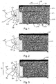
Figure 1 is a partial side view of a tabletop section in accordance with an embodiment of the present invention locked to a second tabletop section with the switch and the lock pin in their respective first positions, and with a side panel of the second tabletop section removed to show the peg of the second tabletop section and the lock pin of the first tabletop section; -
Figure 2 is a partial side view of the tabletop section ofFigure 1 connected to the second tabletop section with the switch and the lock pin in their respective second positions; -
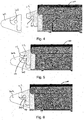
Figure 3 is a partial side view of the tabletop section ofFigure 2 having been disconnected from the second tabletop section with the switch and the lock pin in their respective second positions; -
Figure 4 is a partial side view of the tabletop section ofFigure 3 distanced from the second tabletop section with the switch and the lock pin in their respective second positions; -
Figure 5 is a partial side view of the tabletop section ofFigure 4 in the process of being connected to the second tabletop section with the switch and the lock pin in their respective second positions; -
Figure 6 is a partial side view of the tabletop section ofFigure 5 connected to the second tabletop section with the switch and the lock pin in their respective second positions; -
Figure 7 is a partial side view of the tabletop section ofFigure 6 locked to the second tabletop section with the switch and the lock pin in their respective first positions; -
Figure 8 is a partial perspective view of the tabletop section in the state shown inFigures 1 and7 with the side panel of the second tabletop section removed; -
Figures 9, 10 and11 are partial perspective views from respective different angles of the tabletop section ofFigure 4 distanced from the second tabletop section with the switch and the lock pin in their respective first positions but with the side panel of the second tabletop section present; and -
Figure 12 is partial perspective view of the tabletop section locked to the second tabletop section in the state shown inFigures 1 and7 but with the side panel of the second tabletop section present. - With reference first to
Figure 12 , there is shown atabletop section 100 connected to asecond tabletop section 200. The first andsecond tabletop sections tabletop 10 of a surgical table 1, whichtabletop 10 provides a patient support surface 12. Each of the first andsecond tabletop sections second tabletop section 200 is usable to support a portion of the torso of a patient, and thefirst tabletop section 100 is usable to support a portion of the torso, or the head, of the patient. - Although not shown in the Figures, in the present embodiment the
second tabletop section 200 is disposed upon, and is coupled to, the top of a column of the surgical table 1. The column is of adjustable height and extends from a base, which stands on a floor. In a variation to this embodiment, the column is not of adjustable height. The base may include wheels for moving the surgical table along the floor. - As is more clearly visible in
Figure 10 , thesecond tabletop section 200 has amain frame 201 and first andsecond connector devices main frame 201 for rotation about an axis A-A that extends in a transverse direction of thetabletop 10. Moreover, the first andsecond connector devices first tabletop section 100 is detachably connected, as will be described in more detail below, to thesecond tabletop section 200 via the first andsecond connector devices first tabletop section 100, together with the first andsecond connector devices main frame 201 of thesecond tabletop section 200 about the axis A-A. Accordingly, the first andsecond tabletop sections - In a variation to the illustrated embodiment, the first and
second connector devices main frame 201, so that the first andsecond connector devices first tabletop section 100 are not rotatable relative to themain frame 201 of thesecond tabletop section 200. - Since the
first tabletop section 100 is detachable from thesecond tabletop section 200, the table 1 may be made compact for storage. Moreover, thefirst tabletop section 100 may be replaced with a tabletop section of a different form to that shown, for supporting a different portion of a patient. - As used herein, a longitudinal axis of the
tabletop 10 is the major axis of thetabletop 10 and a transverse axis of thetabletop 10 is the orthogonal minor axis of thetabletop 10. A longitudinal direction of thetabletop 10 is parallel to the major axis and a transverse direction of thetabletop 10 is parallel to the minor axis. That is, the transverse direction of thetabletop 10 is perpendicular to, or orthogonal to, the longitudinal direction oftabletop 10. - With reference again to
Figure 12 , thefirst tabletop section 100 will now be described in more detail. Broadly speaking, thefirst tabletop section 100 comprises first andsecond side members 102, 104 and aplate 106 attached to the tops of, and extending between, the first andsecond side members 102, 104. To each of theside members 102, 104 is connected a respective bar 102a, 104a, to which accessories for use in surgery or examination of a patient may be clamped. - The
first tabletop section 100 has first andsecond sides second sides second sides second side members 102, 104, whereas the first and second ends 107, 108 are defined primarily by theplate 106, but also by opposite longitudinal ends of the first andsecond side members 102, 104. The first and second ends 107, 108 extend substantially parallel to a first direction (marked as D1 inFigure 12 ), which is a transverse direction of thetabletop 10. Moreover, the first andsecond side members 102, 104 are spaced apart in a direction parallel to the first direction D1 and theplate 106 extends in a direction parallel to the first direction D1 between the first andsecond side members 102, 104. On the other hand, the first andsecond sides second side members 102, 104, extend substantially parallel to a second direction (marked as D2 inFigure 12 ), which is a longitudinal direction of thetabletop 10. The second direction D2 is thus perpendicular to the first direction D1. - At the
first end 107 of thefirst tabletop section 100, thefirst tabletop section 100 comprises first andsecond connectors 110, 120. Each of theconnectors 110, 120 is connected to a respective one of the first andsecond side members 102, 104, so that theconnectors 110, 120 are spaced apart in a direction parallel to the first direction D1. Thesecond connector 120 is substantially the same as the first connector 110, except that it is a mirror image about the longitudinal axis of thetabletop 10. Accordingly, for conciseness, only the first connector 110 will now be described in detail, with reference toFigures 1, 2 ,8 ,10 and11 . - The first connector 110 comprises a
hook 112 and alock pin 115. Although in other embodiments thehook 112 could take a different form, in the illustrated embodiment thehook 112 takes the form of an inverted, or upside-down, J. Thehook 112 lies in a first plane, to which first plane the first direction D1 is normal. Thehook 112 is disposed around aspace 113 in the first plane and defines anopening 114 into thespace 113, which opening 114 also is in the first plane. Theopening 114 is below thespace 113 in normal use of thefirst tabletop section 100 and the surgical table 1. Thespace 113 is for receiving acylindrical peg 203 of thefirst connector device 202 of thesecond tabletop section 200, as will be described in more detail below. - The
lock pin 115 is for locking the first connector 110 to thesecond tabletop section 200, more specifically to thefirst connector device 202 of thesecond tabletop section 200. Thelock pin 115 is moveable linearly in a direction parallel to the second direction D2 within the first side member 102 and relative to thehook 112 to change a degree to which thelock pin 115 blocks theopening 114 in the first plane. Indeed, thelock pin 115 is restricted to movement in a direction parallel to the second direction D2 and in the first plane. Thelock pin 115 is movable relative to thehook 112 between first and second positions. InFigures 1 ,8 ,10 and11 , thelock pin 115 is at the first position relative to thehook 112, whereas, inFigure 2 , thelock pin 115 is at the second position relative to thehook 112. From consideration of these Figures it will be appreciated that, when thelock pin 115 is at the first position, thelock pin 115 blocks theopening 114 to a greater degree than when thelock pin 115 is at the second position. Thelock pin 115 is biased towards the first position by a biasing device (not shown). - In the illustrated embodiment, the
opening 114 is only partially blocked by thelock pin 115 when thelock pin 115 is at the first position. However, in variations to the illustrated embodiment, theopening 114 is fully blocked by thelock pin 115 when thelock pin 115 is at the first position. - Although the
second connector 120 will not be described in detail, it is to be noted that thesecond connector 120 comprises a second hook, a second space and a second opening, corresponding to thehook 112,space 113 and opening 114 of the first connector 110, which second hook, second space and second opening lie in a second plane that is parallel to and spaced from the first plane. - With reference again to
Figure 12 , the first andsecond sides first side 103 is visible in the Figures). More specifically, the first and second handle portions 103a comprise first and second recesses 103c in the first andsecond side members 102, 104 that define the first andsecond sides second side members 102, 104 that is recessed from an outer face of the one of the first andsecond side members 102, 104 towards the other of the first andsecond side members 102, 104. Each of the first and second recesses 103c is defined by a wall 103b (only the first wall 103b of the first handle portion 103a is visible in the Figures) of the respective first and second handle portions 103a, which wall 103b extends from the outer face of the one of the first andsecond side members 102, 104 towards the other of the first andsecond side members 102, 104. Each of the recesses 103c can be considered a respective undercut portion of thefirst tabletop section 100. That is, the recesses 103c are located below part of the material forming the respective first andsecond side members 102, 104 in normal use of thefirst tabletop section 100 and the surgical table 1. - A centre of mass of the first tabletop section 100 (i.e. the
first tabletop section 100 in isolation and disconnected from the second tabletop section 200) is between the first and second handle portions 103a. That is, the second direction D2 is normal to a plane that passes through the first and second handle portions 103a and through the centre of mass of thefirst tabletop section 100. Moreover, in the illustrated embodiment, the centre of mass of thefirst tabletop section 100 is approximately midway between the first and second handle portions 103a. Accordingly, the first and second handle portions 103a are disposed relative to the rest of thefirst tabletop section 100 so that a user is best able to manipulate and hold thefirst tabletop section 100, during transport of thefirst tabletop section 100 and during connection to and disconnection from thesecond tabletop section 200, by gripping the first and second handle portions 103a with their hands. - In the present embodiment, an axis extending in a direction parallel to the first direction D1 and through the first and second handle portions 103a passes through the centre of mass of the
first tabletop section 100. In variations to the illustrated embodiment, such an axis extending in a direction parallel to the first direction D1 and through the first and second handle portions 103a is offset from the centre of mass of thefirst tabletop section 100 in a direction parallel to a third direction (marked as D3 inFigures 3 and12 ) perpendicular to each of the first and second directions D1, D2. - The
first tabletop section 100 further comprises first and second user-operable switches 109 (although only thefirst switch 109 at the first handle portion 103a is visible in the Figures) at the respective first and second handle portions 103a. Thefirst switch 109 is for moving thelock pin 115 of the first connector 110 relative to thehook 112 of the first connector 110 and the first handle portion 103a, thereby to change the degree to which thelock pin 115 of the first connector 110 blocks theopening 114 of the first connector 110. The second switch is for moving the second lock pin of thesecond connector 120 relative to the second hook of the second connector and the second handle portion, thereby to change the degree to which the second lock pin of the second connector blocks the second opening of the second connector. The second switch is substantially the same as thefirst switch 109 so, for conciseness, only thefirst switch 109 will now be described in detail. - The
first switch 109 is movably located within ahole 103d in the first wall 103b. More specifically, thehole 103d is in a portion of the first wall 103b that faces away from the plate 106 (downwards during normal use of thefirst tabletop section 100 and the surgical table 1), and thefirst switch 109 is movable linearly in a direction parallel to the third direction (marked as D3 inFigures 3 and12 ) perpendicular to each of the first and second directions D1, D2 for moving thelock pin 115 relative to thehook 112 to change the degree to which thelock pin 115 blocks theopening 114. - While in the illustrated embodiment the
first switch 109 is movable linearly in a direction parallel to the third direction D3, in variations to the illustrated embodiment thefirst switch 109 may be movable linearly in a direction having only a component parallel to the third direction D3. In some such variations, the movement of thefirst switch 109 may be in a direction having a component parallel to the first direction D1 or the second direction D2, in addition to the component parallel to the third direction D3. In other such variations, thefirst switch 109 may be movable rotationally relative to the first wall 103b, so that the movement of thefirst switch 109 may be in a direction having a component parallel to the first direction D1 and/or the second direction D2, in addition to the component parallel to the third direction D3. Such rotational movement of thefirst switch 109 relative to the first wall 103b may be about an axis that extends in a transverse direction of thetabletop 10, i.e. in a direction parallel to the first direction D1. - The
first switch 109 is movable relative to the first wall 103b between first and second positions. Movement of the first switch relative to the first wall 103b from the first position to the second position is in an upwards direction in normal use of thefirst tabletop section 100 and the surgical table 1. That is, the movement is movement of thefirst switch 109 towards a plane in which theplate 106 lies, to which plane the third direction D3 is normal. - In
Figures 1 and7 , thefirst switch 109 is at the first position relative to the first wall 103b, whereas, in each ofFigures 2 to 6 , thefirst switch 109 is at the second position relative to the first wall 103b. From consideration of these Figures it will be appreciated that, when thefirst switch 109 is at the first position, a greater degree of thefirst switch 109 is disposed in the first recess 103c than when thefirst switch 109 is at the second position. Thefirst switch 109 is biased towards the first position by a biasing device (not shown). Moreover, thefirst switch 109 is mechanically linked to thelock pin 115 so that movement of thefirst switch 109 from the first position to the second position of thefirst switch 109 causes movement of thelock pin 115 from the first position to the second position of thelock pin 115. - It will be appreciated that the second switch (not shown) correspondingly is movably located within a hole in the second wall, is movable in the same manner as the
first switch 109, and is mechanically linked to the second lock pin of thesecond connector 120 so that movement of the second switch from its first position to its second position causes movement of the second lock pin of thesecond connector 120 from its first position to its second position. - In variations to the illustrated embodiment the second switch may be omitted. In some such variations, the
first switch 109 also is mechanically linked to the second lock pin of thesecond connector 120 so that movement of thefirst switch 109 from its first position to its second position causes movement of the second lock pin of thesecond connector 120 from its first position to its second position. In other such variations, thesecond connector 120 may be omitted, so that the first connector 110 is the only connector of thefirst tabletop section 100 for connecting thefirst tabletop section 100 to thesecond tabletop second 200. - Disconnection and subsequent connection of the
first tabletop section 100 to thesecond tabletop section 200 will now be described with reference to the Figures. - In
Figures 1 and8 , thefirst tabletop section 100 is shown with theswitch 109 and thelock pin 115 in their respective first positions. Thepeg 203 of thefirst connector device 202 of thesecond tabletop section 200 is located in theopening 114. Correspondingly, although not shown in the Figures, the second switch and the second lock pin are in their respective first positions, and a second peg of thesecond connector device 204 of thesecond tabletop section 200 is located in the second opening of thesecond connector 120. Thus, thefirst tabletop section 100 is locked to thesecond tabletop section 200, since thelock pin 115 blocks theopening 114 to a sufficient degree to prevent removal of thepeg 203 from thespace 113, and the second lock pin blocks the second opening to a sufficient degree to prevent removal of the second peg of thesecond connector device 204 from the second space of thesecond connector 120. Moreover, a downward-facingportion 116 of the hook 12 rests on an upward-facingledge 206 of thefirst connector device 202 of thesecond tabletop section 200. Correspondingly, although not shown in the Figures, a downward-facing portion of the second hook of thesecond connector 120 rests on an upward-facing ledge of thesecond connector device 204 of thesecond tabletop section 200. Accordingly, thefirst tabletop section 100 is supported by thesecond tabletop section 200. - In order to unlock the
first tabletop section 100 from thesecond tabletop section 200, a user grasps the first and second handle portions 103a with their hands, so that fingers on their respective left and right hands contact the first and second walls 103b and the index fingers of their respective left and right hands contact thefirst switch 109 and the second switch, respectively. The user then moves their index fingers in a direction having at least a component parallel to the third direction D3, so as to move the first andsecond switches 109, against the bias of the biasing devices (not shown), from their respective first positions to their respective second positions, thereby to move thelock pin 115 of the first connector 110 and the second lock pin of thesecond connector 120 from their respective first positions to their respective second positions, to reach the state shown inFigure 2 . - Once the lock pins 115 of the
connectors 110, 120 are at their respective second positions, the lock pins 115 no longer block theopenings 114 to a sufficient degree to prevent removal of thepegs 203 from thespaces 113. Accordingly, the user can then use their fingers to exert a force in a direction having at least a component parallel to the third direction D3, so as to lift the wholefirst tabletop section 100 from thesecond tabletop section 200 in a direction parallel to the third direction D3. This movement removes the first andsecond pegs 203 from the first andsecond spaces 113 via the first andsecond openings 114, parts the downward-facingportion 116 of the hook 12 from the upward-facingledge 206 of thefirst connector device 202 of thesecond tabletop section 200, and parts the downward-facing portion of the second hook of thesecond connector 120 from the upward-facing ledge of thesecond connector device 204 of thesecond tabletop section 200, thereby to disconnect thefirst tabletop section 100 from thesecond tabletop section 200, to reach the state shown inFigure 3 . - It will be noted that the user does not need to change their grip on the
first tabletop section 100 between first moving the first andsecond switches 109 to their respective second positions and subsequently lifting the wholefirst tabletop section 100 from thesecond tabletop section 200. Accordingly, thefirst tabletop section 100 is easy to manipulate during disconnection from thesecond tabletop section 200. - Once the first and
second pegs 203 have been removed from the first andsecond spaces 113 of the first andsecond connectors 110, 120, the user is able to transport thefirst tabletop section 100 away from thesecond tabletop section 200, as shown inFigures 4 , and9 to 11 . Since the user is holding thefirst tabletop section 100 by gripping the first and second handle portions 103a with their hands, and since the centre of mass of thefirst tabletop section 100 is between the first and second handle portions 103a, thefirst tabletop section 100 is easy to manipulate during transport. At any time after disconnecting thefirst tabletop section 100 from thesecond tabletop section 200, the user is able to release the first andsecond switches 109 to permit the biasing device to move the first andsecond switches 109 and the first and second lock pins 115 their respective first positions. - The user is able to connect the
first tabletop section 100 to thesecond tabletop section 200 by reversing the order of these steps, as follows. - The user grasps the first and second handle portions 103a with their hands, so that fingers on their respective left and right hands contact the first and second walls 103b and the index fingers of their respective left and right hands contact the
first switch 109 and the second switch, respectively. The user then moves their index fingers in a direction having at least a component parallel to the third direction D3, so as to move the first andsecond switches 109, against the bias of the biasing devices (not shown), from their respective first positions to their respective second positions, thereby to move thelock pin 115 of the first connector 110 and the second lock pin of thesecond connector 120 from their respective first positions to their respective second positions, to reach the state shown inFigures 4 and9 to 11 . - The user then moves the
first tabletop section 100 relative to thesecond tabletop section 200 thereby to align the first andsecond pegs 203 with the first andsecond openings 114 of the first andsecond connectors 110, 120, to reach the state shown inFigure 5 . - With the lock first and
second pins 115 of the first andsecond connectors 110, 120 at their respective second positions, the first and second lock pins 115 do not block the first andsecond openings 114 to a sufficient degree to prevent movement of the first andsecond pegs 203 through the first andsecond openings 114 into the first andsecond spaces 113. Accordingly, the user can then lower thefirst tabletop section 100 relative to thesecond tabletop section 200 in a direction parallel to the third direction D3 to cause the first andsecond pegs 203 to enter the first andsecond spaces 113 through the first andsecond openings 114, to cause the downward-facingportion 116 of the hook 12 to rest on the upward-facingledge 206 of thefirst connector device 202 of thesecond tabletop section 200, and to cause the downward-facing portion of the second hook of thesecond connector 120 to rest on the upward-facing ledge of thesecond connector device 204 of thesecond tabletop section 200, thereby to connect thefirst tabletop section 100 with thesecond tabletop section 200, to reach the state shown inFigure 6 . - The user is then able to release the first and
second switches 109 to permit the biasing devices to move the first andsecond switches 109 and the first and second lock pins 115 their respective first positions, to reach the state shown inFigure 7 . Thelock pin 115 then blocks theopening 114 to a sufficient degree to prevent removal of thepeg 203 from thespace 113, and the second lock pin blocks the second opening to a sufficient degree to prevent removal of the second peg of thesecond connector device 204 from the second space of thesecond connector 120. Thus, thefirst tabletop section 100 is locked to thesecond tabletop section 200. - It will be noted that the user does not need to change their grip on the
first tabletop section 100 between first moving the first andsecond switches 109 to their respective second positions and subsequently connecting thefirst tabletop section 100 with thesecond tabletop section 200. Accordingly, thefirst tabletop section 100 is easy to manipulate during connection with thesecond tabletop section 200. - Various modifications can be made to the above-described embodiments without departing from the scope of the present invention, which is defined by the claims.
Claims (17)
- A combination of a first tabletop section (100) and a second tabletop section (200) for a surgical table (1), the first tabletop section comprising a first connector (110) for connecting the first tabletop section to the second tabletop section, the first connector having a hook (112) disposed around a space (113) and defining an opening (114) into the space, and a lock pin (115) for locking the connector to the second tabletop section, the lock pin being movable relative to the hook to change a degree to which the lock pin blocks the opening, characterised in that the lock pin is movable linearly relative to the hook to change the degree to which the lock pin blocks the opening, wherein the second tabletop section comprises a peg (203), and wherein the space is for receiving the peg of the second tabletop section.
- The combination tabletop sections (100, 200) according to claim 1, wherein the hook (112) lies in a first plane and the opening (114) is in the first plane.
- The combination tabletop sections (100, 200) according to claim 1 or claim 2, comprising first and second ends (107, 108) extending substantially parallel to a first direction (D1), and first and second sides (103, 105) connecting the first and second ends, each of the first and second sides extending substantially parallel to a second direction (D2) perpendicular to the first direction, wherein the first connector (110) is at the first end, optionally wherein the first and second sides comprise respective first and second handle portions (103a).
- The combination tabletop sections (100, 200) according to claim 3, when dependent on claim 2, wherein the first direction (D1) is normal to the first plane.
- The combination tabletop sections (100, 200) according to any one of claims 2 to 4, wherein the lock pin (115) is movable in the first plane relative to the hook (112) to change the degree to which the lock pin blocks the opening (114), optionally wherein the lock pin is restricted to movement in the first plane relative to the hook to change the degree to which the lock pin blocks the opening.
- The combination tabletop sections (100, 200) according to any one of claims 3 to 5, wherein the lock pin (115) is movable in a direction parallel to the second direction (D2) relative to the hook (112) to change the degree to which the lock pin blocks the opening (114).
- The combination tabletop sections (100, 200) according to any preceding claim, comprising a switch (109) for moving the lock pin (115) relative to the hook (112) to change the degree to which the lock pin blocks the opening (114).
- The combination tabletop sections (100, 200) according to claim 7, when dependent on any one of claims 3 to 6, wherein the switch (109) is movable in a direction having at least a component parallel to a third direction (D3) perpendicular to each of the first and second directions (D1, D2) for moving the lock pin (115) relative to the hook (112) to change the degree to which the lock pin blocks the opening (114), optionally wherein the switch is movable one of linearly and rotationally.
- The combination tabletop sections (100, 200) according to claim 7 or claim 8, when dependent on any one of claims 3 to 8, wherein the first and second handle portions (103a) comprise first and second walls (103b) defining respective first and second recesses (103c) in the first and second sides (103, 105), and wherein the switch (109) is movably located within a hole (103d) in the first wall.
- The combination tabletop sections (100, 200) according to claim 9, wherein the switch (109) is movable relative to the first wall (103b) between a first position and a second position, wherein when the switch is at the first position a greater degree of the switch is disposed in the first recess (103c) than when the switch is at the second position, and wherein the switch is biased towards the first position.
- The combination tabletop sections (100, 200) according to any preceding claim, wherein the lock pin (115) is movable relative to the hook (112) between a first position and a second position, wherein when the lock pin is at the first position the lock pin blocks the opening (114) to a greater degree than when the lock pin is at the second position, and wherein the lock pin is biased towards the first position.
- The combination tabletop sections (100, 200) according to claim 11, when dependent on claim 10, wherein movement of the switch (109) from the first position to the second position causes movement of the lock pin (115) from the first position to the second position.
- The combination tabletop sections (100, 200) according to any preceding claim, comprising a second connector (120) for connecting the first tabletop section to the second tabletop section, the second connector having a second hook disposed around a second space and defining a second opening into the second space, and a second lock pin movable relative to the second hook to change a degree to which the second lock pin blocks the second opening, wherein the second connector is spaced from the first connector (110).
- The combination tabletop sections (100, 200) according to claim 13, wherein the second hook lies in a second plane and the second opening is in the second plane.
- The combination tabletop sections (100, 200) according to claim 14, when dependent on any one of claims 2 to 13, wherein the second plane is parallel to and spaced from the first plane.
- The combination tabletop sections (100, 200) according to any one of claims 1 to 15, wherein the second tabletop section (200) is a tabletop section that is disposed upon, and coupled to, a column of a surgical table (1).
- A surgical table (1) comprising the combination tabletop sections (100, 200) according to any one of claims 1 to 15.
Applications Claiming Priority (2)
| Application Number | Priority Date | Filing Date | Title |
|---|---|---|---|
| GB1312522.4A GB2516109B (en) | 2013-07-12 | 2013-07-12 | Tabletop sections for surgical tables |
| PCT/EP2014/064473 WO2015004068A2 (en) | 2013-07-12 | 2014-07-07 | Tabletop sections for surgical tables |
Publications (2)
| Publication Number | Publication Date |
|---|---|
| EP3019134A2 EP3019134A2 (en) | 2016-05-18 |
| EP3019134B1 true EP3019134B1 (en) | 2018-03-14 |
Family
ID=49081198
Family Applications (1)
| Application Number | Title | Priority Date | Filing Date |
|---|---|---|---|
| EP14738793.0A Active EP3019134B1 (en) | 2013-07-12 | 2014-07-07 | Tabletop sections for surgical tables |
Country Status (6)
| Country | Link |
|---|---|
| US (1) | US10159617B2 (en) |
| EP (1) | EP3019134B1 (en) |
| AU (1) | AU2014289368A1 (en) |
| CA (1) | CA2917670A1 (en) |
| GB (3) | GB2535054B (en) |
| WO (1) | WO2015004068A2 (en) |
Families Citing this family (2)
| Publication number | Priority date | Publication date | Assignee | Title |
|---|---|---|---|---|
| GB2535054B (en) * | 2013-07-12 | 2017-01-11 | Eschmann Holdings Ltd | Tabletop sections for surgical tables |
| CN211356501U (en) * | 2019-11-05 | 2020-08-28 | 通快医疗系统两合公司 | Supporting plate connecting device of operating table extension unit and operating table |
Family Cites Families (28)
| Publication number | Priority date | Publication date | Assignee | Title |
|---|---|---|---|---|
| JPS5442894A (en) | 1977-09-12 | 1979-04-05 | Morita Mfg | Working mechanism of treatment table and treatment table device that use said table |
| JPH01297054A (en) | 1988-05-25 | 1989-11-30 | Toshiba Corp | Medical device |
| GB2273868B (en) * | 1992-09-24 | 1997-04-09 | Snell Elizabeth | Improvements relating to surgical tables |
| JP2862446B2 (en) | 1992-10-07 | 1999-03-03 | 三菱電機株式会社 | Treatment table equipment |
| DE59407423D1 (en) | 1993-06-14 | 1999-01-21 | Helmut Schuster | Transport device for patients or bedridden people |
| US6038718A (en) * | 1994-08-15 | 2000-03-21 | Midmark Corporation | Surgical table |
| US6739006B2 (en) * | 1997-11-07 | 2004-05-25 | Hill-Rom Services, Inc. | Head section support for a surgical table apparatus |
| DE19751329B4 (en) * | 1997-11-19 | 2015-05-21 | Trumpf Medizin Systeme Gmbh + Co. Kg | Additional module for an operating table and operating table with additional module |
| JP2002519111A (en) * | 1998-06-26 | 2002-07-02 | ヒル−ロム,インコーポレイティド | Prone bed |
| US6195820B1 (en) * | 1999-05-27 | 2001-03-06 | Hill-Rom, Inc. | Pivoting hand table |
| FR2813928B1 (en) * | 2000-09-12 | 2003-09-26 | Alm | ASSEMBLY OF TWO PARTS OF WHICH ONE IS FIXED AND THE OTHER REMOVABLE, FOR USE FOR EXAMPLE FOR THE EQUIPMENT OF A SURGICAL TABLE |
| CA2435548A1 (en) * | 2001-01-25 | 2002-08-01 | Richard L. Borders | Head section support for a surgical table |
| SE523388C2 (en) | 2001-06-27 | 2004-04-13 | Bertil Lohman Design Ab | Enclosure for electronic devices with a slot for insertion card and contact element for electrical connection between a panel for insertion card and an appliance housing |
| US6698044B2 (en) * | 2002-03-30 | 2004-03-02 | Saul P. Greenfield | Pediatric stirrup device and method |
| US7669262B2 (en) * | 2004-11-10 | 2010-03-02 | Allen Medical Systems, Inc. | Accessory frame for spinal surgery |
| US20070136947A1 (en) * | 2005-10-14 | 2007-06-21 | Limpert Clifford P | Medical table clamp and accessory including same |
| WO2010039102A1 (en) | 2008-09-30 | 2010-04-08 | Agency For Science, Technology And Research | Powered caster wheel assembly |
| TW201034646A (en) * | 2009-03-17 | 2010-10-01 | Amtai Medical Equipment Co Ltd | Operating table |
| US8746710B2 (en) | 2010-05-17 | 2014-06-10 | Linet Spol S.R.O. | Patient support apparatus having an auxiliary wheel |
| US20120063838A1 (en) * | 2010-09-15 | 2012-03-15 | Rajeev Sahu | Docking mechanism for patient tables |
| DE102010051126A1 (en) | 2010-11-11 | 2012-05-16 | Berchtold Holding Gmbh | operating table |
| AU2012287169B2 (en) * | 2011-07-22 | 2015-09-10 | Stryker Corporation | Multi-position limb holder |
| KR101332637B1 (en) * | 2011-11-09 | 2013-11-25 | 제이더블유중외메디칼 주식회사 | Separation type bed |
| US9121421B2 (en) * | 2011-11-23 | 2015-09-01 | Elekta Ab (Publ) | Interface and support mechanism |
| US8997281B2 (en) * | 2012-03-23 | 2015-04-07 | Trumpf Medizin Systeme Gmbh + Co. Kg | Operating table top assemblies and related devices |
| US8966687B2 (en) * | 2012-05-22 | 2015-03-03 | Civco Medical Instruments Co., Inc. | Joint assembly for connecting a long extension panel to a patient support panel of a radiation therapy table and a two-piece patient support table formed thereby |
| GB2535054B (en) * | 2013-07-12 | 2017-01-11 | Eschmann Holdings Ltd | Tabletop sections for surgical tables |
| DE102016216996A1 (en) * | 2016-09-07 | 2018-03-08 | Trumpf Medizin Systeme Gmbh + Co. Kg | Connection device and method for unlocking the connection device |
-
2013
- 2013-07-12 GB GB1606240.8A patent/GB2535054B/en active Active
- 2013-07-12 GB GB1606232.5A patent/GB2534738B/en active Active
- 2013-07-12 GB GB1312522.4A patent/GB2516109B/en active Active
-
2014
- 2014-07-07 EP EP14738793.0A patent/EP3019134B1/en active Active
- 2014-07-07 US US14/904,143 patent/US10159617B2/en active Active
- 2014-07-07 CA CA2917670A patent/CA2917670A1/en not_active Abandoned
- 2014-07-07 AU AU2014289368A patent/AU2014289368A1/en not_active Abandoned
- 2014-07-07 WO PCT/EP2014/064473 patent/WO2015004068A2/en not_active Ceased
Also Published As
| Publication number | Publication date |
|---|---|
| WO2015004068A2 (en) | 2015-01-15 |
| GB2535054A (en) | 2016-08-10 |
| AU2014289368A1 (en) | 2016-02-25 |
| GB2535054B (en) | 2017-01-11 |
| US10159617B2 (en) | 2018-12-25 |
| GB2516109B (en) | 2016-10-12 |
| WO2015004068A3 (en) | 2015-05-14 |
| GB2534738A (en) | 2016-08-03 |
| EP3019134A2 (en) | 2016-05-18 |
| CA2917670A1 (en) | 2015-01-15 |
| GB201312522D0 (en) | 2013-08-28 |
| US20160143798A1 (en) | 2016-05-26 |
| GB2534738B (en) | 2017-01-11 |
| GB2516109A (en) | 2015-01-14 |
Similar Documents
| Publication | Publication Date | Title |
|---|---|---|
| KR102245543B1 (en) | Patient platform connection device | |
| JP6630290B2 (en) | Furniture support frame | |
| KR102068867B1 (en) | Surgery table attachment apparatus | |
| KR102356218B1 (en) | A system of an adjustable support apparatus for a surgery table | |
| EP2617405B1 (en) | Leg support for a surgical table | |
| EP4049556B1 (en) | Locking mechanism | |
| CA3111814A1 (en) | Storage device | |
| EP3135263B1 (en) | Bed with a stowable siderail | |
| US10159617B2 (en) | Tabletop sections for surgical tables | |
| EP4233823B1 (en) | Patient lift apparatus | |
| KR101272310B1 (en) | Angle adjustable device of upper board for table | |
| AU2017245336B2 (en) | Joint assembly for connecting a long extension panel to a patient support panel of a radiation therapy table and a two-piece patient support table formed thereby | |
| KR101272499B1 (en) | Locking apparatus of side rail for a bed | |
| JP2009247883A (en) | Collapsible handle and bag with it | |
| US20200281785A1 (en) | Patient support device | |
| EP3944787B1 (en) | Extendable table | |
| JP3164271U (en) | Rollaway bed | |
| JP2016097236A (en) | Locking mechanism of lifting platform having top board lifted up and down | |
| CN111134968A (en) | Patient transfer device | |
| CN212509755U (en) | Adjustable ball valve lock | |
| CN108784994A (en) | Fold mechanism and obstetric table with the fold mechanism | |
| EP3569213B1 (en) | Patient platform connection device | |
| JP2026512132A (en) | Frame, seat locking device, and stroller | |
| AU2016201155B2 (en) | An adjustable support apparatus for a surgery table | |
| JP2017093137A (en) | Scaffolding device for insulator |
Legal Events
| Date | Code | Title | Description |
|---|---|---|---|
| PUAI | Public reference made under article 153(3) epc to a published international application that has entered the european phase |
Free format text: ORIGINAL CODE: 0009012 |
|
| 17P | Request for examination filed |
Effective date: 20160129 |
|
| AK | Designated contracting states |
Kind code of ref document: A2 Designated state(s): AL AT BE BG CH CY CZ DE DK EE ES FI FR GB GR HR HU IE IS IT LI LT LU LV MC MK MT NL NO PL PT RO RS SE SI SK SM TR |
|
| AX | Request for extension of the european patent |
Extension state: BA ME |
|
| DAX | Request for extension of the european patent (deleted) | ||
| GRAP | Despatch of communication of intention to grant a patent |
Free format text: ORIGINAL CODE: EPIDOSNIGR1 |
|
| STAA | Information on the status of an ep patent application or granted ep patent |
Free format text: STATUS: GRANT OF PATENT IS INTENDED |
|
| INTG | Intention to grant announced |
Effective date: 20171005 |
|
| GRAS | Grant fee paid |
Free format text: ORIGINAL CODE: EPIDOSNIGR3 |
|
| GRAA | (expected) grant |
Free format text: ORIGINAL CODE: 0009210 |
|
| STAA | Information on the status of an ep patent application or granted ep patent |
Free format text: STATUS: THE PATENT HAS BEEN GRANTED |
|
| AK | Designated contracting states |
Kind code of ref document: B1 Designated state(s): AL AT BE BG CH CY CZ DE DK EE ES FI FR GB GR HR HU IE IS IT LI LT LU LV MC MK MT NL NO PL PT RO RS SE SI SK SM TR |
|
| REG | Reference to a national code |
Ref country code: GB Ref legal event code: FG4D |
|
| REG | Reference to a national code |
Ref country code: CH Ref legal event code: EP Ref country code: AT Ref legal event code: REF Ref document number: 978142 Country of ref document: AT Kind code of ref document: T Effective date: 20180315 |
|
| REG | Reference to a national code |
Ref country code: IE Ref legal event code: FG4D |
|
| REG | Reference to a national code |
Ref country code: DE Ref legal event code: R096 Ref document number: 602014022341 Country of ref document: DE |
|
| REG | Reference to a national code |
Ref country code: NL Ref legal event code: MP Effective date: 20180314 |
|
| REG | Reference to a national code |
Ref country code: LT Ref legal event code: MG4D |
|
| REG | Reference to a national code |
Ref country code: FR Ref legal event code: PLFP Year of fee payment: 5 |
|
| PG25 | Lapsed in a contracting state [announced via postgrant information from national office to epo] |
Ref country code: HR Free format text: LAPSE BECAUSE OF FAILURE TO SUBMIT A TRANSLATION OF THE DESCRIPTION OR TO PAY THE FEE WITHIN THE PRESCRIBED TIME-LIMIT Effective date: 20180314 Ref country code: LT Free format text: LAPSE BECAUSE OF FAILURE TO SUBMIT A TRANSLATION OF THE DESCRIPTION OR TO PAY THE FEE WITHIN THE PRESCRIBED TIME-LIMIT Effective date: 20180314 Ref country code: NO Free format text: LAPSE BECAUSE OF FAILURE TO SUBMIT A TRANSLATION OF THE DESCRIPTION OR TO PAY THE FEE WITHIN THE PRESCRIBED TIME-LIMIT Effective date: 20180614 Ref country code: FI Free format text: LAPSE BECAUSE OF FAILURE TO SUBMIT A TRANSLATION OF THE DESCRIPTION OR TO PAY THE FEE WITHIN THE PRESCRIBED TIME-LIMIT Effective date: 20180314 Ref country code: CY Free format text: LAPSE BECAUSE OF FAILURE TO SUBMIT A TRANSLATION OF THE DESCRIPTION OR TO PAY THE FEE WITHIN THE PRESCRIBED TIME-LIMIT Effective date: 20180314 |
|
| REG | Reference to a national code |
Ref country code: AT Ref legal event code: MK05 Ref document number: 978142 Country of ref document: AT Kind code of ref document: T Effective date: 20180314 |
|
| PG25 | Lapsed in a contracting state [announced via postgrant information from national office to epo] |
Ref country code: LV Free format text: LAPSE BECAUSE OF FAILURE TO SUBMIT A TRANSLATION OF THE DESCRIPTION OR TO PAY THE FEE WITHIN THE PRESCRIBED TIME-LIMIT Effective date: 20180314 Ref country code: GR Free format text: LAPSE BECAUSE OF FAILURE TO SUBMIT A TRANSLATION OF THE DESCRIPTION OR TO PAY THE FEE WITHIN THE PRESCRIBED TIME-LIMIT Effective date: 20180615 Ref country code: SE Free format text: LAPSE BECAUSE OF FAILURE TO SUBMIT A TRANSLATION OF THE DESCRIPTION OR TO PAY THE FEE WITHIN THE PRESCRIBED TIME-LIMIT Effective date: 20180314 Ref country code: RS Free format text: LAPSE BECAUSE OF FAILURE TO SUBMIT A TRANSLATION OF THE DESCRIPTION OR TO PAY THE FEE WITHIN THE PRESCRIBED TIME-LIMIT Effective date: 20180314 Ref country code: BG Free format text: LAPSE BECAUSE OF FAILURE TO SUBMIT A TRANSLATION OF THE DESCRIPTION OR TO PAY THE FEE WITHIN THE PRESCRIBED TIME-LIMIT Effective date: 20180614 |
|
| PG25 | Lapsed in a contracting state [announced via postgrant information from national office to epo] |
Ref country code: RO Free format text: LAPSE BECAUSE OF FAILURE TO SUBMIT A TRANSLATION OF THE DESCRIPTION OR TO PAY THE FEE WITHIN THE PRESCRIBED TIME-LIMIT Effective date: 20180314 Ref country code: IT Free format text: LAPSE BECAUSE OF FAILURE TO SUBMIT A TRANSLATION OF THE DESCRIPTION OR TO PAY THE FEE WITHIN THE PRESCRIBED TIME-LIMIT Effective date: 20180314 Ref country code: AL Free format text: LAPSE BECAUSE OF FAILURE TO SUBMIT A TRANSLATION OF THE DESCRIPTION OR TO PAY THE FEE WITHIN THE PRESCRIBED TIME-LIMIT Effective date: 20180314 Ref country code: ES Free format text: LAPSE BECAUSE OF FAILURE TO SUBMIT A TRANSLATION OF THE DESCRIPTION OR TO PAY THE FEE WITHIN THE PRESCRIBED TIME-LIMIT Effective date: 20180314 Ref country code: PL Free format text: LAPSE BECAUSE OF FAILURE TO SUBMIT A TRANSLATION OF THE DESCRIPTION OR TO PAY THE FEE WITHIN THE PRESCRIBED TIME-LIMIT Effective date: 20180314 Ref country code: EE Free format text: LAPSE BECAUSE OF FAILURE TO SUBMIT A TRANSLATION OF THE DESCRIPTION OR TO PAY THE FEE WITHIN THE PRESCRIBED TIME-LIMIT Effective date: 20180314 Ref country code: NL Free format text: LAPSE BECAUSE OF FAILURE TO SUBMIT A TRANSLATION OF THE DESCRIPTION OR TO PAY THE FEE WITHIN THE PRESCRIBED TIME-LIMIT Effective date: 20180314 |
|
| PG25 | Lapsed in a contracting state [announced via postgrant information from national office to epo] |
Ref country code: AT Free format text: LAPSE BECAUSE OF FAILURE TO SUBMIT A TRANSLATION OF THE DESCRIPTION OR TO PAY THE FEE WITHIN THE PRESCRIBED TIME-LIMIT Effective date: 20180314 Ref country code: SM Free format text: LAPSE BECAUSE OF FAILURE TO SUBMIT A TRANSLATION OF THE DESCRIPTION OR TO PAY THE FEE WITHIN THE PRESCRIBED TIME-LIMIT Effective date: 20180314 Ref country code: CZ Free format text: LAPSE BECAUSE OF FAILURE TO SUBMIT A TRANSLATION OF THE DESCRIPTION OR TO PAY THE FEE WITHIN THE PRESCRIBED TIME-LIMIT Effective date: 20180314 Ref country code: SK Free format text: LAPSE BECAUSE OF FAILURE TO SUBMIT A TRANSLATION OF THE DESCRIPTION OR TO PAY THE FEE WITHIN THE PRESCRIBED TIME-LIMIT Effective date: 20180314 |
|
| REG | Reference to a national code |
Ref country code: DE Ref legal event code: R097 Ref document number: 602014022341 Country of ref document: DE |
|
| PG25 | Lapsed in a contracting state [announced via postgrant information from national office to epo] |
Ref country code: PT Free format text: LAPSE BECAUSE OF FAILURE TO SUBMIT A TRANSLATION OF THE DESCRIPTION OR TO PAY THE FEE WITHIN THE PRESCRIBED TIME-LIMIT Effective date: 20180716 |
|
| PLBE | No opposition filed within time limit |
Free format text: ORIGINAL CODE: 0009261 |
|
| STAA | Information on the status of an ep patent application or granted ep patent |
Free format text: STATUS: NO OPPOSITION FILED WITHIN TIME LIMIT |
|
| PG25 | Lapsed in a contracting state [announced via postgrant information from national office to epo] |
Ref country code: DK Free format text: LAPSE BECAUSE OF FAILURE TO SUBMIT A TRANSLATION OF THE DESCRIPTION OR TO PAY THE FEE WITHIN THE PRESCRIBED TIME-LIMIT Effective date: 20180314 |
|
| 26N | No opposition filed |
Effective date: 20181217 |
|
| PG25 | Lapsed in a contracting state [announced via postgrant information from national office to epo] |
Ref country code: SI Free format text: LAPSE BECAUSE OF FAILURE TO SUBMIT A TRANSLATION OF THE DESCRIPTION OR TO PAY THE FEE WITHIN THE PRESCRIBED TIME-LIMIT Effective date: 20180314 |
|
| REG | Reference to a national code |
Ref country code: CH Ref legal event code: PL |
|
| GBPC | Gb: european patent ceased through non-payment of renewal fee |
Effective date: 20180707 |
|
| PG25 | Lapsed in a contracting state [announced via postgrant information from national office to epo] |
Ref country code: MC Free format text: LAPSE BECAUSE OF FAILURE TO SUBMIT A TRANSLATION OF THE DESCRIPTION OR TO PAY THE FEE WITHIN THE PRESCRIBED TIME-LIMIT Effective date: 20180314 Ref country code: LU Free format text: LAPSE BECAUSE OF NON-PAYMENT OF DUE FEES Effective date: 20180707 |
|
| REG | Reference to a national code |
Ref country code: BE Ref legal event code: MM Effective date: 20180731 |
|
| REG | Reference to a national code |
Ref country code: IE Ref legal event code: MM4A |
|
| PG25 | Lapsed in a contracting state [announced via postgrant information from national office to epo] |
Ref country code: IE Free format text: LAPSE BECAUSE OF NON-PAYMENT OF DUE FEES Effective date: 20180707 Ref country code: CH Free format text: LAPSE BECAUSE OF NON-PAYMENT OF DUE FEES Effective date: 20180731 Ref country code: LI Free format text: LAPSE BECAUSE OF NON-PAYMENT OF DUE FEES Effective date: 20180731 Ref country code: GB Free format text: LAPSE BECAUSE OF NON-PAYMENT OF DUE FEES Effective date: 20180707 |
|
| PG25 | Lapsed in a contracting state [announced via postgrant information from national office to epo] |
Ref country code: BE Free format text: LAPSE BECAUSE OF NON-PAYMENT OF DUE FEES Effective date: 20180731 |
|
| PG25 | Lapsed in a contracting state [announced via postgrant information from national office to epo] |
Ref country code: MT Free format text: LAPSE BECAUSE OF NON-PAYMENT OF DUE FEES Effective date: 20180707 |
|
| PG25 | Lapsed in a contracting state [announced via postgrant information from national office to epo] |
Ref country code: TR Free format text: LAPSE BECAUSE OF FAILURE TO SUBMIT A TRANSLATION OF THE DESCRIPTION OR TO PAY THE FEE WITHIN THE PRESCRIBED TIME-LIMIT Effective date: 20180314 |
|
| PG25 | Lapsed in a contracting state [announced via postgrant information from national office to epo] |
Ref country code: MK Free format text: LAPSE BECAUSE OF NON-PAYMENT OF DUE FEES Effective date: 20180314 Ref country code: HU Free format text: LAPSE BECAUSE OF FAILURE TO SUBMIT A TRANSLATION OF THE DESCRIPTION OR TO PAY THE FEE WITHIN THE PRESCRIBED TIME-LIMIT; INVALID AB INITIO Effective date: 20140707 |
|
| PG25 | Lapsed in a contracting state [announced via postgrant information from national office to epo] |
Ref country code: IS Free format text: LAPSE BECAUSE OF FAILURE TO SUBMIT A TRANSLATION OF THE DESCRIPTION OR TO PAY THE FEE WITHIN THE PRESCRIBED TIME-LIMIT Effective date: 20180714 |
|
| REG | Reference to a national code |
Ref country code: DE Ref legal event code: R082 Ref document number: 602014022341 Country of ref document: DE Representative=s name: PAGE, WHITE & FARRER GERMANY LLP, DE Ref country code: DE Ref legal event code: R081 Ref document number: 602014022341 Country of ref document: DE Owner name: STERIS SOLUTIONS LTD., SYSTON, GB Free format text: FORMER OWNER: ESCHMANN HOLDINGS LTD., LANCING, WEST SUSSEX, GB |
|
| P01 | Opt-out of the competence of the unified patent court (upc) registered |
Effective date: 20230513 |
|
| PGFP | Annual fee paid to national office [announced via postgrant information from national office to epo] |
Ref country code: DE Payment date: 20250729 Year of fee payment: 12 |
|
| PGFP | Annual fee paid to national office [announced via postgrant information from national office to epo] |
Ref country code: FR Payment date: 20250725 Year of fee payment: 12 |
|
| REG | Reference to a national code |
Ref country code: DE Ref legal event code: R082 Ref document number: 602014022341 Country of ref document: DE Representative=s name: WESTPHAL, MUSSGNUG & PARTNER PATENTANWAELTE MI, DE |