EP3019089B1 - Hemostatic device - Google Patents
Hemostatic device Download PDFInfo
- Publication number
- EP3019089B1 EP3019089B1 EP14822893.5A EP14822893A EP3019089B1 EP 3019089 B1 EP3019089 B1 EP 3019089B1 EP 14822893 A EP14822893 A EP 14822893A EP 3019089 B1 EP3019089 B1 EP 3019089B1
- Authority
- EP
- European Patent Office
- Prior art keywords
- outer tube
- carrier
- housing
- plunger
- hemostatic device
- Prior art date
- Legal status (The legal status is an assumption and is not a legal conclusion. Google has not performed a legal analysis and makes no representation as to the accuracy of the status listed.)
- Not-in-force
Links
- 230000002439 hemostatic effect Effects 0.000 title claims description 68
- 239000012530 fluid Substances 0.000 claims description 13
- 238000007789 sealing Methods 0.000 claims description 10
- 238000007599 discharging Methods 0.000 claims description 4
- 239000003795 chemical substances by application Substances 0.000 description 31
- 238000000034 method Methods 0.000 description 14
- 239000008280 blood Substances 0.000 description 11
- 210000004369 blood Anatomy 0.000 description 11
- 230000000717 retained effect Effects 0.000 description 9
- 206010033675 panniculitis Diseases 0.000 description 6
- 210000004304 subcutaneous tissue Anatomy 0.000 description 6
- 102000008186 Collagen Human genes 0.000 description 2
- 108010035532 Collagen Proteins 0.000 description 2
- 210000001367 artery Anatomy 0.000 description 2
- 229920001436 collagen Polymers 0.000 description 2
- 230000023597 hemostasis Effects 0.000 description 2
- 239000000017 hydrogel Substances 0.000 description 2
- 239000000463 material Substances 0.000 description 2
- 229920000642 polymer Polymers 0.000 description 2
- 210000001519 tissue Anatomy 0.000 description 2
- 230000002792 vascular Effects 0.000 description 2
- 230000000007 visual effect Effects 0.000 description 2
- 230000017531 blood circulation Effects 0.000 description 1
- 210000004204 blood vessel Anatomy 0.000 description 1
- 210000001124 body fluid Anatomy 0.000 description 1
- 239000010839 body fluid Substances 0.000 description 1
- 230000000747 cardiac effect Effects 0.000 description 1
- 230000005465 channeling Effects 0.000 description 1
- 230000015271 coagulation Effects 0.000 description 1
- 238000005345 coagulation Methods 0.000 description 1
- 230000003247 decreasing effect Effects 0.000 description 1
- 230000007717 exclusion Effects 0.000 description 1
- 239000000203 mixture Substances 0.000 description 1
- 230000002093 peripheral effect Effects 0.000 description 1
- 238000010992 reflux Methods 0.000 description 1
- 239000003566 sealing material Substances 0.000 description 1
- 239000000126 substance Substances 0.000 description 1
- -1 without limitation Substances 0.000 description 1
Images





Classifications
-
- A—HUMAN NECESSITIES
- A61—MEDICAL OR VETERINARY SCIENCE; HYGIENE
- A61B—DIAGNOSIS; SURGERY; IDENTIFICATION
- A61B17/00—Surgical instruments, devices or methods
- A61B17/0057—Implements for plugging an opening in the wall of a hollow or tubular organ, e.g. for sealing a vessel puncture or closing a cardiac septal defect
-
- A—HUMAN NECESSITIES
- A61—MEDICAL OR VETERINARY SCIENCE; HYGIENE
- A61B—DIAGNOSIS; SURGERY; IDENTIFICATION
- A61B17/00—Surgical instruments, devices or methods
- A61B17/0057—Implements for plugging an opening in the wall of a hollow or tubular organ, e.g. for sealing a vessel puncture or closing a cardiac septal defect
- A61B2017/00646—Type of implements
- A61B2017/0065—Type of implements the implement being an adhesive
-
- A—HUMAN NECESSITIES
- A61—MEDICAL OR VETERINARY SCIENCE; HYGIENE
- A61B—DIAGNOSIS; SURGERY; IDENTIFICATION
- A61B17/00—Surgical instruments, devices or methods
- A61B17/0057—Implements for plugging an opening in the wall of a hollow or tubular organ, e.g. for sealing a vessel puncture or closing a cardiac septal defect
- A61B2017/00646—Type of implements
- A61B2017/00654—Type of implements entirely comprised between the two sides of the opening
-
- A—HUMAN NECESSITIES
- A61—MEDICAL OR VETERINARY SCIENCE; HYGIENE
- A61B—DIAGNOSIS; SURGERY; IDENTIFICATION
- A61B17/00—Surgical instruments, devices or methods
- A61B17/0057—Implements for plugging an opening in the wall of a hollow or tubular organ, e.g. for sealing a vessel puncture or closing a cardiac septal defect
- A61B2017/00672—Locating means therefor, e.g. bleed back lumen
-
- A—HUMAN NECESSITIES
- A61—MEDICAL OR VETERINARY SCIENCE; HYGIENE
- A61B—DIAGNOSIS; SURGERY; IDENTIFICATION
- A61B90/00—Instruments, implements or accessories specially adapted for surgery or diagnosis and not covered by any of the groups A61B1/00 - A61B50/00, e.g. for luxation treatment or for protecting wound edges
- A61B90/08—Accessories or related features not otherwise provided for
- A61B2090/0807—Indication means
Definitions
- the subject matter described herein relates generally to medical devices and, more particularly, to a hemostatic device configured to seal a puncture of a vessel.
- Catheter introducers are known to provide access to an artery for at least some medical procedures including, without limitation, cardiac catheterizations and peripheral endovascular procedures. After conducting such medical procedures, the catheter introducer is removed from the access site, leaving an arterial opening. At least some body fluids including, without limitation, blood are discharged from the arterial opening. Excess blood loss may endanger and/or traumatize the patient.
- One known method of controlling blood loss is through direct manual pressure over the arterial opening.
- a device for controlling such blood loss is disclosed in U.S. Patent Publication No. 2009/0171282 , which describes a closure sheath insertable into a tissue tract and configured to slidably receive a vascular closure device therethrough.
- the vascular closure device includes a central vessel locator tube received within a carrier tube.
- a core wire extends through the locator tube.
- a handle at a proximal end of the device includes a first tube that slidably receives the carrier tube at a distal end, and slidably receives a second tube at a proximal end.
- the second tube is coupled to the core wire via an actuation member.
- the actuation member is operable to retract and extend the core wire relative to the locator tube, which in turn expands and contracts a locating member at a distal end of the device.
- another actuation member extends outward from the carrier tube through a slot in the first tube.
- the second actuation member is operable to retract and extend the carrier tube with respect to the locator tube. After the closure sheath is withdrawn, retraction of the carrier tube exposes a sealing material within the carrier tube to the tissue tract.
- actuation of the device is relatively complex.
- a hemostatic device for sealing a puncture of a vessel as claimed in claim 1.
- the methods and apparatus described herein relate to medical devices and, more particularly, to a hemostatic device for use in sealing a puncture of a vessel.
- the hemostatic device described herein facilitates sealing an opening of a blood vessel.
- the hemostatic device includes a first tube defining a first lumen configured to channel a fluid therethrough, and a second tube housing at least a portion of the first tube and at least partially defining a second lumen configured to retain a hemocoagulant agent therein.
- the second tube is moveable with respect to the first tube, such that the hemocoagulant agent is at least substantially retained within the second lumen when the second tube is in a first position, and the hemocoagulant agent is at least partially exposed when the second tube is in a second position.
- the hemocoagulant agent is discharged from the second lumen and seals the opening to reduce a time required for hemostasis and/or ambulation.
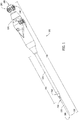
- FIG. 1 is a perspective view of an exemplary hemostatic device 100 for sealing a puncture of a vessel (not shown).
- hemostatic device 100 includes a first or inner tube 110 and a second or outer tube 120.
- hemostatic device 100 has a distal end 130, a proximal end 140, and a length 150.
- length 150 is at least approximately 12.7 cm (5 inches (in.)). More particularly, length 150 is between approximately 20.32 cm (8 in.) and approximately 30.48 cm (12 in.). Even more particularly, length 150 is approximately 25.77 cm (10.147 in.).
- hemostatic device 100 may have any length that enables the methods and systems to function as described herein.
- a distal end of inner tube 110 is tapered to facilitate traversing through subcutaneous tissue and into a lumen of the vessel.
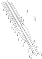
- FIG. 2 is a cross-sectional view of a first portion of hemostatic device 100 in a closed configuration
- FIG. 3 is a cross-sectional view of the first portion in a deployed configuration.
- inner tube 110 includes a sidewall 170 that defines a first or inner lumen 160 configured to channel blood or, more broadly, a fluid therethrough.
- sidewall 170 includes a first opening 180 (shown in FIG. 1 ) at a distal end of inner lumen 160, and a second opening 190 (shown in FIG. 1 ) at a proximal end of inner lumen 160.
- first opening 180 is sized to receive a guidewire (not shown), and second opening 190 is sized to channel the fluid through inner lumen 160 about the guidewire.
- First opening 180 and/or second opening 190 may have any size, shape, and/or configuration that enables inner tube 110 to function as described herein.
- a valve 200 (shown in FIG. 1 ) proximate to second opening 190 is selectively movable between an open configuration and a closed configuration. More particularly, valve 200 is actuatable towards the closed configuration to selectively restrict access to second opening 190 and/or inner lumen 160. That is, in the exemplary embodiment, valve 200 enables second opening 190 to be at least partially closed such that a flow of the fluid through inner lumen 160 is decreased. Moreover, in the exemplary embodiment, valve 200 is actuatable towards the open configuration to selectively provide access to second opening 190 and/or inner lumen 160. That is, in the exemplary embodiment, valve 200 enables second opening 190 to be at least partially opened such that a flow of the fluid through inner lumen 160 is increased.
- inner tube 110 includes a distal portion 210 and a proximal portion 220 coupled to distal portion 210 by an interference fit.
- inner tube 110 may include any number of portions, and/or the portions may be coupled in any configuration and/or using any mechanism that enables inner tube 110 to function as described herein.
- outer tube 120 houses proximal portion 220 of inner tube 110, and distal portion 210 is generally exposed, such that outer tube 120 does not house distal portion 210 of inner tube 110.
- distal portion 210 includes a side opening 230 extending through sidewall 170 that is in fluid communication with inner lumen 160 such that fluid may enter inner lumen 160 through side opening 230.
- outer tube 120 includes a sidewall 260 that at least partially defines a second or outer lumen 240 (shown in FIG. 2 ) configured to retain a hemocoagulant agent 250 therein.
- hemocoagulant agent 250 is an FDA-approved hydrogel polymer or collagen patch.
- hemocoagulant agent 250 may be any substance and/or composition that enables outer tube 120 to function as described herein.
- outer tube 120 houses at least a portion of inner tube 110.
- outer tube 120 is translatable or longitudinally moveable with respect to inner tube 110, such that hemocoagulant agent 250 is at least substantially retained within outer lumen 240 when outer tube 120 is in a first or closed position, and is at least partially exposed to the environment when outer tube 120 is in a second or open position.
- Outer tube 120 is slideable in the distal direction towards the closed position to substantially retain hemocoagulant agent 250 within outer lumen 240, and is slideable in the proximal direction towards the open position to expose hemocoagulant agent 250 to the environment.
- inner tube 110 and outer tube 120 may move in any direction that enables hemostatic device 100 to function as described herein.
- hemostatic device 100 includes a plug 270 that at least partially circumscribes inner tube 110.
- plug 270 includes a distal portion 280 having a distal apex 290 oriented towards the distal end of hemostatic device 100, and a proximal portion 300 having a step 310 and a proximal apex 320 oriented towards the proximal end of hemostatic device 100.
- plug 270 is positioned with respect to inner tube 110, such that plug 270 and/or a distal end of outer tube 120 are positionable outside and substantially adjacent an access site and/or a vessel when inner tube side opening 230 is within the lumen of the vessel.
- plug distal portion 280 is substantially cone-shaped to facilitate traversing plug 270 through subcutaneous tissue
- plug proximal portion 300 is substantially cone-shaped to facilitate channeling or directing hemocoagulant agent 250 radially outward from hemostatic device 100.
- plug proximal portion 300 is oriented and/or configured to channel or direct at least some of hemocoagulant agent 250 away from inner tube 110 and/or a center axis of hemostatic device 100 to facilitate reducing a coagulation of hemocoagulant agent 250 within outer lumen 240.
- step 310 is configured to interface and/or receive a distal end of outer tube 120, such that hemocoagulant agent 250 is at least substantially retained within outer lumen 240 when hemostatic device 100 is in a closed configuration.
- Step 310 enables outer tube 120 to be sealingly coupled to plug 270, such that hemocoagulant agent 250 is at least substantially retained within outer lumen 240.
- plug 270 is fabricated at least partially from a soft and/or pliable material that enables a seal to be provided at the plug-outer tube interface, the vessel, and/or the access site.
- plug 270 may be fabricated from, without limitation, rubber and/or a rubber-like material.
- plug 270 may have any configuration that enables plug 270 to function as described herein.
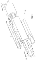
- FIGS. 4 and 5 are cross-sectional views of a second portion of hemostatic device 100 in a closed configuration
- FIG. 6 is a cross-sectional view of the second portion in a deployed configuration.
- hemostatic device 100 includes a housing 330 and an actuating mechanism 340 positioned within housing 330. More specifically, housing 330 includes a sidewall 350 that defines a cavity 360, and actuating mechanism 340 includes a first or an outer tube carrier 370 that is moveable within cavity 360 between a distal end of cavity 360 and a proximal end of cavity 360.
- outer tube carrier 370 is coupled to outer tube 120 such that outer tube 120 moves between the closed position and the open position as outer tube carrier 370 is moved between the distal end of cavity 360 and the proximal end of cavity 360, respectively.
- outer tube 120 may be moved towards the open position and/or the closed position using any mechanism that enables outer tube 120 to function as described herein.
- a distance 380 (shown in FIG. 1 ) between side opening 230 and a distal end of housing 330 is at least approximately 5.08 cm (2 in). More particularly, distance 380 is between approximately 7.62 cm (3 in.) and approximately 15.24 cm (6 in). Even more particularly, distance 380 is approximately 10.668 cm (4.2 in). Alternatively, distance 380 may be any length that enables the methods and systems to function as described herein. In the exemplary embodiment, distance 380 remains substantially constant as at least a portion of outer tube 120 is selectively retracted into and/or extended from housing 330 when outer tube 120 is moved between the closed position and the open position.
- hemostatic device 100 includes a rotating mechanism 390 coupled to outer tube carrier 370.
- rotating mechanism 390 is configured to move outer tube carrier 370 towards the distal end of cavity 360 as rotating mechanism 390 is rotated in a first direction (e.g., a counterclockwise direction when looking from proximal end 140 towards distal end 130) and move outer tube carrier 370 towards the proximal end of cavity 360 as rotating mechanism 390 is rotated in a second direction (e.g., a clockwise direction when looking from proximal end 140 towards distal end 130).
- Rotating mechanism 390 is configured to convert rotational movement into axial movement.
- rotating mechanism 390 includes a wheel 400 and a body 410 extending from wheel 400 and at least partially positioned within outer tube carrier 370.
- wheel 400 has a diameter that is greater than and/or equal to a width of housing 330.
- a peg (not shown) extending from an inner surface of outer tube carrier 370 is retained in a groove 420 (shown in FIG. 4 ) defined in an outer surface of body 410.
- groove 420 includes a first segment 430 (shown in FIG. 4 ) that extends helically about a central axis of body 410 and a second segment 440 (shown in FIG. 4 ) that at least partially circumscribes body 410.
- outer tube carrier 370 longitudinally moves with respect to rotating mechanism 390 between the distal end of cavity 360 and the proximal end of cavity 360 as wheel 400 is rotated when the peg is within first segment 430.
- outer tube carrier 370 is substantially longitudinally stationary with respect to rotating mechanism 390 as wheel 400 is rotated when the peg is within second segment 440.
- outer tube carrier 370 may be moved between the distal end of cavity 360 and the proximal end of cavity 360 using any mechanism that enables outer tube 120 to function as described herein.
- second segment 440 fully circumscribes body 410 to enable wheel 400 to be continuously rotated when the peg is within second segment 440.
- outer tube carrier 370 is at the proximal end of cavity 360 when the peg is within second segment 440.
- hemostatic device 100 includes a first retaining mechanism 450 (shown in FIG. 4 ) that facilitates preventing outer tube carrier 370 from rotating with respect to housing 330 as wheel 400 is rotated in the first direction and/or in the second direction.
- retaining mechanism 450 includes a peg (not shown) extending from an inner surface of housing 330, and a slot 460 (shown in FIG. 4 ) defined in an outer surface of outer tube carrier 370 sized to retain the peg.
- slot 460 extends substantially longitudinally along the outer surface of outer tube carrier 370, such that outer tube carrier 370 is longitudinally moveable, while substantially not rotating, with respect to housing 330 as the peg is moved between a distal end of slot 460 and a proximal end of slot 460.
- outer tube 120 may be moved and/or restricted from movement using any mechanism that enables outer tube 120 to function as described herein.
- hemostatic device 100 includes a plunging mechanism 470 (shown in FIGS. 5 and 6 ) including a plunger 480 (shown in FIGS. 2 , 3 , 5 , and 6 ) at least partially positioned within outer lumen 240 (shown in FIGS. 2 and 3 ), and a second or plunger carrier 490 (shown in FIGS. 5 and 6 ) moveable within a cavity defined by outer tube carrier 370 and/or a cavity defined by rotating mechanism body 410 to facilitate discharging hemocoagulant agent 250.
- a plunging mechanism 470 shown in FIGS. 5 and 6
- plunger 480 shown in FIGS. 2 , 3 , 5 , and 6
- second or plunger carrier 490 shown in FIGS. 5 and 6
- a peg (not shown) extending from an inner surface of rotating mechanism body 410 is retained in a groove 500 (shown in FIGS. 5 and 6 ) defined in an outer surface of plunger carrier 490.
- groove 500 extends helically about a central axis of plunger carrier 490 in a direction that is opposite the direction associated with groove 420.
- plunger 480 is longitudinally moveable, with respect to outer tube 120, in a direction that is opposite the direction outer tube carrier 370 moves with respect to housing 330 as wheel 400 is rotated.
- wheel 400 is selectively rotatable in the first direction to simultaneously move outer tube 120 towards the closed position and plunger 480 towards a retracted or proximal position, or move outer tube 120 towards the open position and plunger 480 towards a dispensing or distal position.
- Groove 420 extends at a first angle with respect to the longitudinal axis
- groove 500 extends at a second angle that is different from the first angle.
- the first angle and/or the second angle are predefined, such that outer tube 120 is configured to move a first distance with each rotation of wheel 400, and plunger 480 is configured to move a second distance with each rotation of wheel 400 that is less than the first distance.
- outer tube 120 and/or plunger 480 may be moved using any mechanism that enables hemostatic device 100 to function as described herein.
- hemostatic device 100 includes a second retaining mechanism 510 that facilitates preventing plunger carrier 490 from rotating with respect to outer tube carrier 370 as wheel 400 is rotated.
- retaining mechanism 510 includes a peg 520 (shown in FIGS. 5 and 6 ) extending from an outer surface of plunger carrier 490, and a slot 530 (shown in FIG. 4 ) defined in an inner surface of outer tube carrier 370 sized to retain peg 520.
- slot 530 extends substantially longitudinally along the inner surface of outer tube carrier 370, such that plunging mechanism 470 is longitudinally moveable, while substantially not rotating, with respect to outer tube carrier 370 as peg 520 is moved between a distal end of slot 530 and a proximal end of slot 530.
- plunging mechanism 470 may be moved and/or restricted from movement using any mechanism that enables plunging mechanism 470 to function as described herein.
- hemostatic device 100 includes a third or intermediate tube 540 (shown in FIGS. 2 and 3 ) positioned radially between inner tube 110 and outer tube 120. More specifically, intermediate tube 540 is positioned such that outer lumen 240 is defined between intermediate tube 540 and outer tube 120, and a third or intermediate lumen 550 (shown in FIGS. 2 and 3 ) configured to channel blood or, more broadly, a fluid therethrough is defined between intermediate tube 540 and inner tube 110.
- intermediate lumen 550 is in fluid communication with a first opening 560 (shown in FIGS. 1-3 ) extending through plug 270 and a second opening 570 (shown in FIG. 1 ) extending through housing 330 such that fluid may enter intermediate lumen 550 through first opening 560 and is dischargeable through second opening 570.
- FIG. 7 is a flow chart illustrating an exemplary method 600 of using hemostatic device 100 to seal a puncture of an artery or vessel with a hydrogel polymer or collagen patch hemocoagulant agent 250.
- hemocoagulant agent 250 is preloaded into hemostatic device 100, such that hemocoagulant agent is retained 610 within outer lumen 240.
- hemocoagulant agent 250 is loaded into hemostatic device 100, such that hemocoagulant agent is retained 610 within outer lumen 240, by selectively rotating wheel 400 and/or substantially enveloping or circumscribing hemocoagulant agent 250 about inner tube 110.
- inner tube 110 is aligned such that a guidewire (not shown) extends through first opening 180 and second opening 190, and inner tube 110 is advanced 620 along the guidewire through subcutaneous tissue until blood is channeled through inner lumen 160 and/or discharged from second opening 190.
- the blood discharge (i.e., reflux) from second opening 190 is a visual indication that inner tube side opening 230 is positioned within the vessel.
- plug 270 provides a tactile indication (e.g., resistance) that plug 270 is positioned outside and substantially adjacent the vessel and/or inner tube side opening 230 is positioned within the vessel.
- valve 200 is moved towards the closed configuration to restrict access to second opening 190 and/or facilitate reducing blood flow through inner lumen 160.
- hemostatic device 100 is advanced along the guidewire too far through subcutaneous tissue.
- the blood enters plug opening 560, is channeled through intermediate lumen 550, and/or is discharged from housing opening 570.
- the blood discharge from housing opening 570 is a visual indication that hemostatic device 100 is advanced too far through subcutaneous tissue and/or should be at least partially withdrawn from the subcutaneous tissue until blood does not discharge from housing opening 570.
- wheel 400 is selectively rotated in the second direction to move hemostatic device 100 towards the deployed configuration and, thus, move 630 outer tube 120 towards the open position.
- hemocoagulant agent 250 is at least partially exposed to the environment.
- plunger carrier 490 and, thus, plunger 480 is moved in the distal direction, such that hemocoagulant agent 250 is pushed at least partially in the distal direction towards plug 270.
- outer tube 120 is moved 630 towards the open position and plunger 480 is moved towards the distal direction simultaneously.
- plug proximal portion 300 channels or directs at least some of hemocoagulant agent 250 radially outward and/or away from a center axis of hemostatic device 100.
- FIG. 8 is a partial cross-sectional view of another exemplary hemostatic device 700 for sealing a puncture of a vessel (not shown).
- Hemostatic device 700 is similar to hemostatic device 100 and, in the absence of a contrary representation, the same reference numbers identify the same or similar elements.
- FIG. 9 is a perspective view of another exemplary hemostatic device 800 for sealing a puncture of a vessel (not shown) in a closed configuration
- FIG. 10 is a perspective view of hemostatic device 800 in a deployed configuration.
- Hemostatic device 800 is similar to hemostatic device 100 and 700 and, in the absence of a contrary representation, the same reference numbers identify the same or similar elements.
- outer tube 120 is longitudinally moveable with respect to inner tube 110, such that hemocoagulant agent 250 is at least substantially retained within outer lumen 240 when outer tube 120 is in the closed position (shown in FIG. 9 ), and is at least partially exposed to the environment when outer tube 120 is in the open position (shown in FIG. 10 ).
- FIG. 11 is a cross-sectional view of hemostatic device 800.
- hemostatic device 800 includes an actuating mechanism 810 that facilitates moving outer tube 120 between the closed position and the open position. More specifically, actuating mechanism 810 is rotated in a first direction (e.g., a clockwise direction when looking from proximal end 140 towards distal end 130) to move outer tube 120 towards the closed position, and is rotated in a second direction (e.g., a counterclockwise direction when looking from proximal end 140 towards distal end 130) to move outer tube 120 towards the open position.
- a first direction e.g., a clockwise direction when looking from proximal end 140 towards distal end 130
- a second direction e.g., a counterclockwise direction when looking from proximal end 140 towards distal end 130
- plunger 480 is moveable within outer lumen 240 to facilitate discharging hemocoagulant agent 250 from outer lumen 240. More specifically, plunger 480 is coupled to a handle 820 (shown in FIGS. 9 and 10 ) configured to move plunger 480 between a retracted or proximal position and a dispensing or distal position.
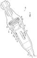
- FIG. 12 is a perspective view of another exemplary hemostatic device 900 for sealing a puncture of a vessel (not shown).
- Hemostatic device 900 is similar to hemostatic devices 100, 700, and 800 and, in the absence of a contrary representation, the same reference numbers identify the same or similar elements.
- plunging mechanism 470 includes a wheel 910 configured to move plunger 480 between a retracted or proximal position and a dispensing or distal position.
- FIGS. 13 and 14 are cross-sectional views of a portion of hemostatic device 800.
- actuating mechanism 810 includes a plurality of threads 920 that enables outer tube 120 to be moved between the closed position and the open position as actuating mechanism 810 is rotated.
- plunging mechanism 470 includes a plunger shaft 930 coupled to wheel 910, and plunger 480 is threadably coupled to plunger shaft 930.
- an inner surface of outer tube 120 and/or an outer surface of plunger 480 is keyed or otherwise not round (e.g., substantially square-shaped) to prevent plunger 480 from rotating with respect to outer tube 120 as plunger shaft 930 is rotated, such that a rotation of wheel 910 and, thus, plunger shaft 930 longitudinally moves plunger 480 with respect to outer tube 120.
- the methods and apparatus described herein relate to medical devices and, more particularly, to a hemostatic device.
- Hemostatic device described herein facilitates sealing, for example, an arterial opening.
- the exemplary hemostatic device includes a first tube defining a first lumen configured to channel a fluid therethrough, and a second tube housing at least a portion of the first tube and at least partially defining a second lumen configured to retain a hemocoagulant agent therein.
- the second tube is at least partially withdrawn to expose at least some of the hemocoagulant agent to the environment while a plunger is moved through the second lumen to facilitate discharging the hemocoagulant agent.
- the hemocoagulant agent facilitates sealing the arterial opening to reduce a time required for hemostasis and/or ambulation.
Landscapes
- Health & Medical Sciences (AREA)
- Surgery (AREA)
- Life Sciences & Earth Sciences (AREA)
- Biomedical Technology (AREA)
- Nuclear Medicine, Radiotherapy & Molecular Imaging (AREA)
- Engineering & Computer Science (AREA)
- Cardiology (AREA)
- Heart & Thoracic Surgery (AREA)
- Medical Informatics (AREA)
- Molecular Biology (AREA)
- Animal Behavior & Ethology (AREA)
- General Health & Medical Sciences (AREA)
- Public Health (AREA)
- Veterinary Medicine (AREA)
- Surgical Instruments (AREA)
Description
- The subject matter described herein relates generally to medical devices and, more particularly, to a hemostatic device configured to seal a puncture of a vessel.
- Catheter introducers are known to provide access to an artery for at least some medical procedures including, without limitation, cardiac catheterizations and peripheral endovascular procedures. After conducting such medical procedures, the catheter introducer is removed from the access site, leaving an arterial opening. At least some body fluids including, without limitation, blood are discharged from the arterial opening. Excess blood loss may endanger and/or traumatize the patient. One known method of controlling blood loss is through direct manual pressure over the arterial opening.
- A device for controlling such blood loss is disclosed in
U.S. Patent Publication No. 2009/0171282 , which describes a closure sheath insertable into a tissue tract and configured to slidably receive a vascular closure device therethrough. The vascular closure device includes a central vessel locator tube received within a carrier tube. A core wire extends through the locator tube. A handle at a proximal end of the device includes a first tube that slidably receives the carrier tube at a distal end, and slidably receives a second tube at a proximal end. The second tube is coupled to the core wire via an actuation member. The actuation member is operable to retract and extend the core wire relative to the locator tube, which in turn expands and contracts a locating member at a distal end of the device. In addition, another actuation member extends outward from the carrier tube through a slot in the first tube. The second actuation member is operable to retract and extend the carrier tube with respect to the locator tube. After the closure sheath is withdrawn, retraction of the carrier tube exposes a sealing material within the carrier tube to the tissue tract. Thus, actuation of the device is relatively complex. - In one aspect, there is provided a hemostatic device for sealing a puncture of a vessel as claimed in claim 1.
- The features, functions, and advantages described herein may be achieved independently in various embodiments of the present disclosure or may be combined in yet other embodiments, further details of which may be seen with reference to the following description and drawings.
-
-
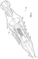
FIG. 1 is a perspective view of an exemplary hemostatic device; -
FIG. 2 is a cross-sectional view of a distal portion of the hemostatic device shown inFIG. 1 in a closed configuration; -
FIG. 3 is a cross-sectional view of the distal portion shown inFIG. 2 in a deployed configuration; -
FIG. 4 is a partial cross-sectional view of a proximal portion of the hemostatic device shown inFIG. 1 in a closed configuration; -
FIG. 5 is a cross-sectional view of the proximal portion shown inFIG. 4 ; -
FIG. 6 is a cross-sectional view of the proximal portion shown inFIG. 4 in a deployed configuration; -
FIG. 7 is a flow chart illustrating an exemplary method of using the hemostatic device shown inFIG. 1 ; -
FIG. 8 is a partial cross-sectional view of another exemplary hemostatic device; -
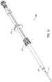
FIG. 9 is a perspective view of yet another exemplary hemostatic device in a closed configuration; -
FIG. 10 is a perspective view of the hemostatic device shown inFIG. 9 in an open configuration; -
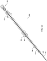
FIG. 11 is a cross-sectional view of the hemostatic device shown inFIG. 9 ; -
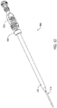
FIG. 12 is a perspective view of yet another exemplary hemostatic device; and -
FIGS. 13 and14 are cross-sectional views of a portion of the hemostatic device shown inFIG. 12 . - The methods and apparatus described herein relate to medical devices and, more particularly, to a hemostatic device for use in sealing a puncture of a vessel. The hemostatic device described herein facilitates sealing an opening of a blood vessel. More particularly, in at least one embodiment, the hemostatic device includes a first tube defining a first lumen configured to channel a fluid therethrough, and a second tube housing at least a portion of the first tube and at least partially defining a second lumen configured to retain a hemocoagulant agent therein. The second tube is moveable with respect to the first tube, such that the hemocoagulant agent is at least substantially retained within the second lumen when the second tube is in a first position, and the hemocoagulant agent is at least partially exposed when the second tube is in a second position. The hemocoagulant agent is discharged from the second lumen and seals the opening to reduce a time required for hemostasis and/or ambulation.
- As used herein, an element or step recited in the singular and preceded with the word "a" or "an" should be understood as not excluding plural said elements or steps, unless such exclusion is explicitly stated. Further, references to an "embodiment" or an "implementation" are not intended to be interpreted as excluding the existence of additional embodiments or implementations that also incorporate the recited features. Moreover, unless explicitly stated to the contrary, embodiments or implementations "comprising," "including," or "having" an element or a plurality of elements having a particular property may include additional such elements not having that property.
-
FIG. 1 is a perspective view of an exemplaryhemostatic device 100 for sealing a puncture of a vessel (not shown). In the exemplary embodiment,hemostatic device 100 includes a first orinner tube 110 and a second orouter tube 120. In the exemplary embodiment,hemostatic device 100 has adistal end 130, aproximal end 140, and alength 150. In the exemplary embodiment,length 150 is at least approximately 12.7 cm (5 inches (in.)). More particularly,length 150 is between approximately 20.32 cm (8 in.) and approximately 30.48 cm (12 in.). Even more particularly,length 150 is approximately 25.77 cm (10.147 in.). Alternatively,hemostatic device 100 may have any length that enables the methods and systems to function as described herein. In the exemplary embodiment, a distal end ofinner tube 110 is tapered to facilitate traversing through subcutaneous tissue and into a lumen of the vessel. -
FIG. 2 is a cross-sectional view of a first portion ofhemostatic device 100 in a closed configuration, andFIG. 3 is a cross-sectional view of the first portion in a deployed configuration. In the exemplary embodiment,inner tube 110 includes asidewall 170 that defines a first orinner lumen 160 configured to channel blood or, more broadly, a fluid therethrough. In the exemplary embodiment,sidewall 170 includes a first opening 180 (shown inFIG. 1 ) at a distal end ofinner lumen 160, and a second opening 190 (shown inFIG. 1 ) at a proximal end ofinner lumen 160. In the exemplary embodiment,first opening 180 is sized to receive a guidewire (not shown), andsecond opening 190 is sized to channel the fluid throughinner lumen 160 about the guidewire. First opening 180 and/orsecond opening 190 may have any size, shape, and/or configuration that enablesinner tube 110 to function as described herein. - In the exemplary embodiment, a valve 200 (shown in
FIG. 1 ) proximate tosecond opening 190 is selectively movable between an open configuration and a closed configuration. More particularly,valve 200 is actuatable towards the closed configuration to selectively restrict access tosecond opening 190 and/orinner lumen 160. That is, in the exemplary embodiment,valve 200 enablessecond opening 190 to be at least partially closed such that a flow of the fluid throughinner lumen 160 is decreased. Moreover, in the exemplary embodiment,valve 200 is actuatable towards the open configuration to selectively provide access tosecond opening 190 and/orinner lumen 160. That is, in the exemplary embodiment,valve 200 enablessecond opening 190 to be at least partially opened such that a flow of the fluid throughinner lumen 160 is increased. - In the exemplary embodiment,
inner tube 110 includes adistal portion 210 and aproximal portion 220 coupled todistal portion 210 by an interference fit. Alternatively,inner tube 110 may include any number of portions, and/or the portions may be coupled in any configuration and/or using any mechanism that enablesinner tube 110 to function as described herein. In the exemplary embodiment,outer tube 120 housesproximal portion 220 ofinner tube 110, anddistal portion 210 is generally exposed, such thatouter tube 120 does not housedistal portion 210 ofinner tube 110. In the exemplary embodiment,distal portion 210 includes aside opening 230 extending throughsidewall 170 that is in fluid communication withinner lumen 160 such that fluid may enterinner lumen 160 throughside opening 230. - In the exemplary embodiment,
outer tube 120 includes asidewall 260 that at least partially defines a second or outer lumen 240 (shown inFIG. 2 ) configured to retain ahemocoagulant agent 250 therein. In one implementation,hemocoagulant agent 250 is an FDA-approved hydrogel polymer or collagen patch. Alternatively,hemocoagulant agent 250 may be any substance and/or composition that enablesouter tube 120 to function as described herein. - In the exemplary embodiment,
outer tube 120 houses at least a portion ofinner tube 110. In the exemplary embodiment,outer tube 120 is translatable or longitudinally moveable with respect toinner tube 110, such thathemocoagulant agent 250 is at least substantially retained withinouter lumen 240 whenouter tube 120 is in a first or closed position, and is at least partially exposed to the environment whenouter tube 120 is in a second or open position.Outer tube 120 is slideable in the distal direction towards the closed position to substantially retainhemocoagulant agent 250 withinouter lumen 240, and is slideable in the proximal direction towards the open position to exposehemocoagulant agent 250 to the environment. Alternatively,inner tube 110 andouter tube 120 may move in any direction that enableshemostatic device 100 to function as described herein. - In the exemplary embodiment,
hemostatic device 100 includes aplug 270 that at least partially circumscribesinner tube 110. In the exemplary embodiment, plug 270 includes adistal portion 280 having adistal apex 290 oriented towards the distal end ofhemostatic device 100, and aproximal portion 300 having astep 310 and aproximal apex 320 oriented towards the proximal end ofhemostatic device 100. In the exemplary embodiment, plug 270 is positioned with respect toinner tube 110, such thatplug 270 and/or a distal end ofouter tube 120 are positionable outside and substantially adjacent an access site and/or a vessel when innertube side opening 230 is within the lumen of the vessel. - In the exemplary embodiment, plug
distal portion 280 is substantially cone-shaped to facilitate traversingplug 270 through subcutaneous tissue, and plugproximal portion 300 is substantially cone-shaped to facilitate channeling or directinghemocoagulant agent 250 radially outward fromhemostatic device 100. In the exemplary embodiment, plugproximal portion 300 is oriented and/or configured to channel or direct at least some ofhemocoagulant agent 250 away frominner tube 110 and/or a center axis ofhemostatic device 100 to facilitate reducing a coagulation ofhemocoagulant agent 250 withinouter lumen 240. - In the exemplary embodiment,
step 310 is configured to interface and/or receive a distal end ofouter tube 120, such thathemocoagulant agent 250 is at least substantially retained withinouter lumen 240 whenhemostatic device 100 is in a closed configuration. Step 310 enablesouter tube 120 to be sealingly coupled to plug 270, such thathemocoagulant agent 250 is at least substantially retained withinouter lumen 240. In the exemplary embodiment, plug 270 is fabricated at least partially from a soft and/or pliable material that enables a seal to be provided at the plug-outer tube interface, the vessel, and/or the access site. For example, plug 270 may be fabricated from, without limitation, rubber and/or a rubber-like material. Alternatively, plug 270 may have any configuration that enables plug 270 to function as described herein. -
FIGS. 4 and5 are cross-sectional views of a second portion ofhemostatic device 100 in a closed configuration, andFIG. 6 is a cross-sectional view of the second portion in a deployed configuration. In the exemplary embodiment,hemostatic device 100 includes ahousing 330 and anactuating mechanism 340 positioned withinhousing 330. More specifically,housing 330 includes asidewall 350 that defines acavity 360, andactuating mechanism 340 includes a first or anouter tube carrier 370 that is moveable withincavity 360 between a distal end ofcavity 360 and a proximal end ofcavity 360. In the exemplary embodiment,outer tube carrier 370 is coupled toouter tube 120 such thatouter tube 120 moves between the closed position and the open position asouter tube carrier 370 is moved between the distal end ofcavity 360 and the proximal end ofcavity 360, respectively. Alternatively,outer tube 120 may be moved towards the open position and/or the closed position using any mechanism that enablesouter tube 120 to function as described herein. - In the exemplary embodiment, a distance 380 (shown in
FIG. 1 ) between side opening 230 and a distal end ofhousing 330 is at least approximately 5.08 cm (2 in). More particularly,distance 380 is between approximately 7.62 cm (3 in.) and approximately 15.24 cm (6 in). Even more particularly,distance 380 is approximately 10.668 cm (4.2 in). Alternatively,distance 380 may be any length that enables the methods and systems to function as described herein. In the exemplary embodiment,distance 380 remains substantially constant as at least a portion ofouter tube 120 is selectively retracted into and/or extended fromhousing 330 whenouter tube 120 is moved between the closed position and the open position. - In the exemplary embodiment,
hemostatic device 100 includes arotating mechanism 390 coupled toouter tube carrier 370. In the exemplary embodiment,rotating mechanism 390 is configured to moveouter tube carrier 370 towards the distal end ofcavity 360 asrotating mechanism 390 is rotated in a first direction (e.g., a counterclockwise direction when looking fromproximal end 140 towards distal end 130) and moveouter tube carrier 370 towards the proximal end ofcavity 360 asrotating mechanism 390 is rotated in a second direction (e.g., a clockwise direction when looking fromproximal end 140 towards distal end 130).Rotating mechanism 390 is configured to
convert rotational movement into axial movement. In the exemplary embodiment,rotating mechanism 390 includes awheel 400 and abody 410 extending fromwheel 400 and at least partially positioned withinouter tube carrier 370. In the exemplary embodiment,wheel 400 has a diameter that is greater than and/or equal to a width ofhousing 330. - In the exemplary embodiment, a peg (not shown) extending from an inner surface of
outer tube carrier 370 is retained in a groove 420 (shown inFIG. 4 ) defined in an outer surface ofbody 410. In the exemplary embodiment,groove 420 includes a first segment 430 (shown inFIG. 4 ) that extends helically about a central axis ofbody 410 and a second segment 440 (shown inFIG. 4 ) that at least partially circumscribesbody 410. In the exemplary embodiment,outer tube carrier 370 longitudinally moves with respect torotating mechanism 390 between the distal end ofcavity 360 and the proximal end ofcavity 360 aswheel 400 is rotated when the peg is withinfirst segment 430. Moreover, in the exemplary embodiment,outer tube carrier 370 is substantially longitudinally stationary with respect torotating mechanism 390 aswheel 400 is rotated when the peg is withinsecond segment 440. Alternatively,outer tube carrier 370 may be moved between the distal end ofcavity 360 and the proximal end ofcavity 360 using any mechanism that enablesouter tube 120 to function as described herein. In at least some implementations,second segment 440 fully circumscribesbody 410 to enablewheel 400 to be continuously rotated when the peg is withinsecond segment 440. In at least some implementations,outer tube carrier 370 is at the proximal end ofcavity 360 when the peg is withinsecond segment 440. - In the exemplary embodiment,
hemostatic device 100 includes a first retaining mechanism 450 (shown inFIG. 4 ) that facilitates preventingouter tube carrier 370 from rotating with respect tohousing 330 aswheel 400 is rotated in the first direction and/or in the second direction. In the exemplary embodiment, retainingmechanism 450 includes a peg (not shown) extending from an inner surface ofhousing 330, and a slot 460 (shown inFIG. 4 ) defined in an outer surface ofouter tube carrier 370 sized to retain the peg. In the exemplary embodiment,slot 460 extends substantially longitudinally along the outer surface ofouter tube carrier 370, such thatouter tube carrier 370 is longitudinally moveable, while substantially not rotating, with respect tohousing 330 as the peg is moved between a distal end ofslot 460 and a proximal end ofslot 460. Alternatively,outer tube 120 may be moved and/or restricted from movement using any mechanism that enablesouter tube 120 to function as described herein. - In the exemplary embodiment,
hemostatic device 100 includes a plunging mechanism 470 (shown inFIGS. 5 and6 ) including a plunger 480 (shown inFIGS. 2 ,3 ,5 , and6 ) at least partially positioned within outer lumen 240 (shown inFIGS. 2 and3 ), and a second or plunger carrier 490 (shown inFIGS. 5 and6 ) moveable within a cavity defined byouter tube carrier 370 and/or a cavity defined by rotatingmechanism body 410 to facilitate discharginghemocoagulant agent 250. - In the exemplary embodiment, a peg (not shown) extending from an inner surface of
rotating mechanism body 410 is retained in a groove 500 (shown inFIGS. 5 and6 ) defined in an outer surface ofplunger carrier 490. In the exemplary embodiment,groove 500 extends helically about a central axis ofplunger carrier 490 in a direction that is opposite the direction associated withgroove 420. In the exemplary embodiment,plunger 480 is longitudinally moveable, with respect toouter tube 120, in a direction that is opposite the directionouter tube carrier 370 moves with respect tohousing 330 aswheel 400 is rotated. For example, in the exemplary embodiment,wheel 400 is selectively rotatable in the first direction to simultaneously moveouter tube 120 towards the closed position andplunger 480 towards a retracted or proximal position, or moveouter tube 120 towards the open position andplunger 480 towards a dispensing or distal position.Groove 420 extends at a first angle with respect to the longitudinal axis, and groove 500 extends at a second angle that is different from the first angle. The first angle and/or the second angle are predefined, such thatouter tube 120 is configured to move a first distance with each rotation ofwheel 400, andplunger 480 is configured to move a second distance with each rotation ofwheel 400 that is less than the first distance. Alternatively,outer tube 120 and/orplunger 480 may be moved using any mechanism that enableshemostatic device 100 to function as described herein. - In the exemplary embodiment,
hemostatic device 100 includes asecond retaining mechanism 510 that facilitates preventingplunger carrier 490 from rotating with respect toouter tube carrier 370 aswheel 400 is rotated. In the exemplary embodiment, retainingmechanism 510 includes a peg 520 (shown inFIGS. 5 and6 ) extending from an outer surface ofplunger carrier 490, and a slot 530 (shown inFIG. 4 ) defined in an inner surface ofouter tube carrier 370 sized to retainpeg 520. In the exemplary embodiment,slot 530 extends substantially longitudinally along the inner surface ofouter tube carrier 370, such thatplunging mechanism 470 is longitudinally moveable, while substantially not rotating, with respect toouter tube carrier 370 aspeg 520 is moved between a distal end ofslot 530 and a proximal end ofslot 530. Alternatively, plungingmechanism 470 may be moved and/or restricted from movement using any mechanism that enables plungingmechanism 470 to function as described herein. - In the exemplary embodiment,
hemostatic device 100 includes a third or intermediate tube 540 (shown inFIGS. 2 and3 ) positioned radially betweeninner tube 110 andouter tube 120. More specifically,intermediate tube 540 is positioned such thatouter lumen 240 is defined betweenintermediate tube 540 andouter tube 120, and a third or intermediate lumen 550 (shown inFIGS. 2 and3 ) configured to channel blood or, more broadly, a fluid therethrough is defined betweenintermediate tube 540 andinner tube 110. In the exemplary embodiment,intermediate lumen 550 is in fluid communication with a first opening 560 (shown inFIGS. 1-3 ) extending throughplug 270 and a second opening 570 (shown inFIG. 1 ) extending throughhousing 330 such that fluid may enterintermediate lumen 550 throughfirst opening 560 and is dischargeable throughsecond opening 570. -
FIG. 7 is a flow chart illustrating an exemplary method 600 of usinghemostatic device 100 to seal a puncture of an artery or vessel with a hydrogel polymer or collagenpatch hemocoagulant agent 250. In at least some implementations,hemocoagulant agent 250 is preloaded intohemostatic device 100, such that hemocoagulant agent is retained 610 withinouter lumen 240. Alternatively,hemocoagulant agent 250 is loaded intohemostatic device 100, such that hemocoagulant agent is retained 610 withinouter lumen 240, by selectively rotatingwheel 400 and/or substantially enveloping or circumscribinghemocoagulant agent 250 aboutinner tube 110. - During operation,
inner tube 110 is aligned such that a guidewire (not shown) extends throughfirst opening 180 andsecond opening 190, andinner tube 110 is advanced 620 along the guidewire through subcutaneous tissue until blood is channeled throughinner lumen 160 and/or discharged fromsecond opening 190. In the exemplary embodiment, the blood discharge (i.e., reflux) fromsecond opening 190 is a visual indication that innertube side opening 230 is positioned within the vessel. Moreover, plug 270 provides a tactile indication (e.g., resistance) that plug 270 is positioned outside and substantially adjacent the vessel and/or innertube side opening 230 is positioned within the vessel. - In the exemplary embodiment,
valve 200 is moved towards the closed configuration to restrict access tosecond opening 190 and/or facilitate reducing blood flow throughinner lumen 160. In at least some implementations,hemostatic device 100 is advanced along the guidewire too far through subcutaneous tissue. In such an implementation, the blood entersplug opening 560, is channeled throughintermediate lumen 550, and/or is discharged fromhousing opening 570. In such an implementation, the blood discharge fromhousing opening 570 is a visual indication thathemostatic device 100 is advanced too far through subcutaneous tissue and/or should be at least partially withdrawn from the subcutaneous tissue until blood does not discharge fromhousing opening 570. - In the exemplary embodiment,
wheel 400 is selectively rotated in the second direction to movehemostatic device 100 towards the deployed configuration and, thus, move 630outer tube 120 towards the open position. Accordingly, in the exemplary embodiment,hemocoagulant agent 250 is at least partially exposed to the environment. Aswheel 400 is selectively rotated in the second direction,plunger carrier 490 and, thus,plunger 480 is moved in the distal direction, such thathemocoagulant agent 250 is pushed at least partially in the distal direction towardsplug 270. In at least some implementations,outer tube 120 is moved 630 towards the open position andplunger 480 is moved towards the distal direction simultaneously. In the exemplary embodiment, plugproximal portion 300 channels or directs at least some ofhemocoagulant agent 250 radially outward and/or away from a center axis ofhemostatic device 100. -
FIG. 8 is a partial cross-sectional view of another exemplaryhemostatic device 700 for sealing a puncture of a vessel (not shown).Hemostatic device 700 is similar tohemostatic device 100 and, in the absence of a contrary representation, the same reference numbers identify the same or similar elements. -
FIG. 9 is a perspective view of another exemplaryhemostatic device 800 for sealing a puncture of a vessel (not shown) in a closed configuration, andFIG. 10 is a perspective view ofhemostatic device 800 in a deployed configuration.Hemostatic device 800 is similar tohemostatic device - In the exemplary embodiment,
outer tube 120 is longitudinally moveable with respect toinner tube 110, such thathemocoagulant agent 250 is at least substantially retained withinouter lumen 240 whenouter tube 120 is in the closed position (shown inFIG. 9 ), and is at least partially exposed to the environment whenouter tube 120 is in the open position (shown inFIG. 10 ). -
FIG. 11 is a cross-sectional view ofhemostatic device 800. In the exemplary embodiment,hemostatic device 800 includes anactuating mechanism 810 that facilitates movingouter tube 120 between the closed position and the open position. More specifically,actuating mechanism 810 is rotated in a first direction (e.g., a clockwise direction when looking fromproximal end 140 towards distal end 130) to moveouter tube 120 towards the closed position, and is rotated in a second direction (e.g., a counterclockwise direction when looking fromproximal end 140 towards distal end 130) to moveouter tube 120 towards the open position. - In the exemplary embodiment,
plunger 480 is moveable withinouter lumen 240 to facilitate discharginghemocoagulant agent 250 fromouter lumen 240. More specifically,plunger 480 is coupled to a handle 820 (shown inFIGS. 9 and10 ) configured to moveplunger 480 between a retracted or proximal position and a dispensing or distal position. -
FIG. 12 is a perspective view of another exemplaryhemostatic device 900 for sealing a puncture of a vessel (not shown).Hemostatic device 900 is similar tohemostatic devices mechanism 470 includes awheel 910 configured to moveplunger 480 between a retracted or proximal position and a dispensing or distal position. -
FIGS. 13 and14 are cross-sectional views of a portion ofhemostatic device 800. In the exemplary embodiment,actuating mechanism 810 includes a plurality ofthreads 920 that enablesouter tube 120 to be moved between the closed position and the open position asactuating mechanism 810 is rotated. - In the exemplary embodiment, plunging
mechanism 470 includes aplunger shaft 930 coupled towheel 910, andplunger 480 is threadably coupled toplunger shaft 930. In the exemplary embodiment, an inner surface ofouter tube 120 and/or an outer surface ofplunger 480 is keyed or otherwise not round (e.g., substantially square-shaped) to preventplunger 480 from rotating with respect toouter tube 120 asplunger shaft 930 is rotated, such that a rotation ofwheel 910 and, thus,plunger shaft 930 longitudinally moves plunger 480 with respect toouter tube 120. - The methods and apparatus described herein relate to medical devices and, more particularly, to a hemostatic device. Hemostatic device described herein facilitates sealing, for example, an arterial opening. The exemplary hemostatic device includes a first tube defining a first lumen configured to channel a fluid therethrough, and a second tube housing at least a portion of the first tube and at least partially defining a second lumen configured to retain a hemocoagulant agent therein. The second tube is at least partially withdrawn to expose at least some of the hemocoagulant agent to the environment while a plunger is moved through the second lumen to facilitate discharging the hemocoagulant agent. The hemocoagulant agent facilitates sealing the arterial opening to reduce a time required for hemostasis and/or ambulation.
- Exemplary embodiments of medical devices are described above in detail. The methods and systems are not limited to the specific embodiments described herein, but rather, operations of the methods and components of the systems may be utilized independently and separately from other operations and/or components described herein. For example, the methods and apparatus described herein may have other industrial and/or consumer applications and are not limited to practice with medical devices as described herein. Rather, one or more embodiments may be implemented and utilized in connection with other industries.
- This written description uses examples to disclose the invention, including the best mode, and also to enable any person skilled in the art to practice the invention, including making and using any devices or systems and performing any incorporated methods. The patentable scope of the invention is defined by the claims, and may include other examples that occur to those skilled in the art.
Claims (8)
- A hemostatic device (100) for sealing a puncture of a vessel, said hemostatic device comprising:a housing (330) comprising a proximal end and a distal end and defining a housing cavity (360) therein, said housing cavity extending between said proximal end and said distal end;an outer tube carrier (370) disposed within said housing cavity, said outer tube carrier moveable within said housing cavity between said housing distal and proximal ends, said outer tube carrier (370) defining an outer tube carrier cavity;a first tube (110) defining a first lumen (160) configured to channel a fluid therethrough, said first tube coupled to said housing;a second tube (120) extending from said housing distal end, said second tube housing at least a portion of the first tube and at least partially defining a second lumen (240) configured to retain a hemocoagulant agent (250) therein, said second tube coupled to said outer tube carrier and moveable therewith relative to said first tube between (i) a closed position configured to substantially retain the hemocoagulant agent within said second lumen when said outer tube carrier is positioned adjacent said housing distal end, and (ii) an open position configured to at least partially expose the hemocoagulant agent when said outer tube carrier is positioned adjacent said housing proximal end;a plunger carrier (490) disposed within said outer tube carrier cavity, said plunger carrier moveable within said outer tube carrier cavity between said housing distal and proximal ends;a plunger (480) coupled to said plunger carrier for movement with said plunger carrier, wherein said plunger is longitudinally moveable within said second lumen in response to movement of said plunger carrier within said outer tube carrier cavity; andan actuating member (400, 410) coupled to, and rotatable with respect to, said housing, said actuating member extending at least partially through said housing, said outer tube carrier and said plunger carrier coupled to said actuating member such that said plunger carrier and said outer tube carrier simultaneously move in opposite directions in response to rotation of said actuating member.
- A hemostatic device in accordance with Claim 1 wherein said outer tube carrier (370) is moveable between said housing (330) proximal and distal ends in response to rotation of said actuating member (400, 410).
- A hemostatic device in accordance with Claim 1 or 2 wherein said actuating member (400, 410) comprises a helical groove (420), and said outer tube carrier comprises a peg received in said helical groove, said peg and said helical groove cooperative to transform rotational motion of said actuating member into longitudinal translation of said outer tube carrier (370).
- A hemostatic device in accordance with any of Claims 1-3 wherein said outer tube carrier (370) comprises a longitudinally extending slot (460), and said housing (330) comprises a retaining peg received in said longitudinally extending slot, said retaining peg and said longitudinally extending slot cooperative to prevent said outer tube carrier from rotating with respect to said housing.
- A hemostatic device in accordance with any of Claims 2-4 wherein said plunger (480) is longitudinally moveable within said second lumen (240) in response to movement of said plunger carrier (490) within said outer tube carrier cavity from adjacent said housing (330) proximal end to adjacent said housing distal to facilitate discharging the hemocoagulant agent (250).
- A hemostatic device in accordance with any of Claims 3-5 wherein said plunger carrier (490) comprises a helical groove (500) and said actuating member (400, 410) comprises a peg received in said helical groove, said peg and said helical groove cooperative to transform rotational motion of said actuating member into longitudinal translation of said plunger carrier, said helical groove of said plunger carrier angled oppositely to said helical groove (420) of said actuating member.
- A hemostatic device in accordance with any of Claims 1-6, wherein said outer tube carrier (370) comprises a longitudinally extending slot (530), and said plunger carrier (490) comprises a retaining peg (520) received in said longitudinally extending slot, said retaining peg and said longitudinally extending slot cooperative to prevent said plunger carrier from rotating with respect to said outer tube carrier.
- A hemostatic device in accordance with any of Claims 1-7 wherein said first tube (110) further comprises a first side opening (230) in fluid communication with said first lumen (160), wherein a distance (380) between said first side opening and said housing (330) remains constant as said outer tube carrier (370) is moved within said outer tube carrier cavity between said distal and proximal ends of said housing cavity (360).
Applications Claiming Priority (2)
| Application Number | Priority Date | Filing Date | Title |
|---|---|---|---|
| US13/940,766 US9839416B2 (en) | 2013-07-12 | 2013-07-12 | Hemostatic device and its methods of use |
| PCT/US2014/046260 WO2015006633A2 (en) | 2013-07-12 | 2014-07-11 | Hemostatic device and its methods of use |
Publications (3)
| Publication Number | Publication Date |
|---|---|
| EP3019089A2 EP3019089A2 (en) | 2016-05-18 |
| EP3019089A4 EP3019089A4 (en) | 2017-03-29 |
| EP3019089B1 true EP3019089B1 (en) | 2019-07-10 |
Family
ID=52277706
Family Applications (1)
| Application Number | Title | Priority Date | Filing Date |
|---|---|---|---|
| EP14822893.5A Not-in-force EP3019089B1 (en) | 2013-07-12 | 2014-07-11 | Hemostatic device |
Country Status (6)
| Country | Link |
|---|---|
| US (2) | US9839416B2 (en) |
| EP (1) | EP3019089B1 (en) |
| AU (1) | AU2014287078A1 (en) |
| CA (1) | CA2914580A1 (en) |
| ES (1) | ES2738278T3 (en) |
| WO (1) | WO2015006633A2 (en) |
Families Citing this family (6)
| Publication number | Priority date | Publication date | Assignee | Title |
|---|---|---|---|---|
| US9131932B2 (en) * | 2013-02-01 | 2015-09-15 | St. Jude Medical Puerto Rico Llc | Dual lumen carrier tube with retractable sleeve and methods |
| US9839416B2 (en) * | 2013-07-12 | 2017-12-12 | Phillips Medical, LLC | Hemostatic device and its methods of use |
| US10085730B2 (en) | 2013-07-12 | 2018-10-02 | Phillips Medical, LLC | Hemostatic device and its methods of use |
| US9628116B2 (en) | 2015-07-14 | 2017-04-18 | At&T Intellectual Property I, L.P. | Apparatus and methods for transmitting wireless signals |
| CN109999316B (en) * | 2019-04-29 | 2021-05-28 | 南通伊诺精密塑胶导管有限公司 | Blood vessel micro-catheter with developing and marking functions |
| WO2024251919A1 (en) * | 2023-06-07 | 2024-12-12 | Vivasure Medical Limited | Delivery system and method for vascular closure implant |
Family Cites Families (89)
| Publication number | Priority date | Publication date | Assignee | Title |
|---|---|---|---|---|
| US4608965A (en) | 1985-03-27 | 1986-09-02 | Anspach Jr William E | Endoscope retainer and tissue retracting device |
| US4738658A (en) * | 1986-09-19 | 1988-04-19 | Aries Medical Incorporated | Tapered hemostatic device for use in conjunction with a catheter for alleviating blood leakage and method for using same |
| USRE34866E (en) | 1987-02-17 | 1995-02-21 | Kensey Nash Corporation | Device for sealing percutaneous puncture in a vessel |
| US4890612A (en) | 1987-02-17 | 1990-01-02 | Kensey Nash Corporation | Device for sealing percutaneous puncture in a vessel |
| US4850960A (en) | 1987-07-08 | 1989-07-25 | Joseph Grayzel | Diagonally tapered, bevelled tip introducing catheter and sheath and method for insertion |
| US4895564A (en) | 1988-06-08 | 1990-01-23 | Farrell Edward M | Percutaneous femoral bypass system |
| US4929246A (en) | 1988-10-27 | 1990-05-29 | C. R. Bard, Inc. | Method for closing and sealing an artery after removing a catheter |
| US5061274A (en) | 1989-12-04 | 1991-10-29 | Kensey Nash Corporation | Plug device for sealing openings and method of use |
| US5391183A (en) | 1990-09-21 | 1995-02-21 | Datascope Investment Corp | Device and method sealing puncture wounds |
| US5108421A (en) | 1990-10-01 | 1992-04-28 | Quinton Instrument Company | Insertion assembly and method of inserting a vessel plug into the body of a patient |
| US6325789B1 (en) | 1990-12-27 | 2001-12-04 | Datascope Investment Corporation | Device and method for sealing puncture wounds |
| US5290310A (en) | 1991-10-30 | 1994-03-01 | Howmedica, Inc. | Hemostatic implant introducer |
| US5411520A (en) * | 1991-11-08 | 1995-05-02 | Kensey Nash Corporation | Hemostatic vessel puncture closure system utilizing a plug located within the puncture tract spaced from the vessel, and method of use |
| US5282827A (en) | 1991-11-08 | 1994-02-01 | Kensey Nash Corporation | Hemostatic puncture closure system and method of use |
| US5222974A (en) | 1991-11-08 | 1993-06-29 | Kensey Nash Corporation | Hemostatic puncture closure system and method of use |
| US5676689A (en) * | 1991-11-08 | 1997-10-14 | Kensey Nash Corporation | Hemostatic puncture closure system including vessel location device and method of use |
| US6699261B1 (en) | 1992-01-07 | 2004-03-02 | Cch Associates, Inc. | Blood vessel sealing system |
| US6056768A (en) | 1992-01-07 | 2000-05-02 | Cates; Christopher U. | Blood vessel sealing system |
| US6818008B1 (en) * | 1992-01-07 | 2004-11-16 | Cch Associates, Inc. | Percutaneous puncture sealing method |
| US5326350A (en) | 1992-05-11 | 1994-07-05 | Li Shu Tung | Soft tissue closure systems |
| US5443481A (en) | 1992-07-27 | 1995-08-22 | Lee; Benjamin I. | Methods and device for percutaneous sealing of arterial puncture sites |
| US5306254A (en) | 1992-10-01 | 1994-04-26 | Kensey Nash Corporation | Vessel position locating device and method of use |
| US5415657A (en) | 1992-10-13 | 1995-05-16 | Taymor-Luria; Howard | Percutaneous vascular sealing method |
| US5951583A (en) | 1993-05-25 | 1999-09-14 | Vascular Solutions, Inc. | Thrombin and collagen procoagulant and process for making the same |
| US5486195A (en) | 1993-07-26 | 1996-01-23 | Myers; Gene | Method and apparatus for arteriotomy closure |
| US5431639A (en) * | 1993-08-12 | 1995-07-11 | Boston Scientific Corporation | Treating wounds caused by medical procedures |
| NL9301526A (en) | 1993-09-03 | 1995-04-03 | Cordis Europ | Device for hemostasis treatment after catheter surgery. |
| US5653730A (en) | 1993-09-28 | 1997-08-05 | Hemodynamics, Inc. | Surface opening adhesive sealer |
| US5843124A (en) | 1993-09-28 | 1998-12-01 | Hemodynamics, Inc. | Surface opening adhesive sealer |
| US5437292A (en) | 1993-11-19 | 1995-08-01 | Bioseal, Llc | Method for sealing blood vessel puncture sites |
| US6302898B1 (en) * | 1994-06-24 | 2001-10-16 | Advanced Closure Systems, Inc. | Devices for sealing punctures in body vessels |
| US5766157A (en) | 1995-03-17 | 1998-06-16 | Tilton, Jr.; Eugene B. | Instrumentation for surgical endoscopic insertion and application of liquid and gel material |
| US6071300A (en) | 1995-09-15 | 2000-06-06 | Sub-Q Inc. | Apparatus and method for percutaneous sealing of blood vessel punctures |
| US5645566A (en) | 1995-09-15 | 1997-07-08 | Sub Q Inc. | Apparatus and method for percutaneous sealing of blood vessel punctures |
| US6162192A (en) | 1998-05-01 | 2000-12-19 | Sub Q, Inc. | System and method for facilitating hemostasis of blood vessel punctures with absorbable sponge |
| US5827304A (en) | 1995-11-16 | 1998-10-27 | Applied Medical Resources Corporation | Intraluminal extraction catheter |
| US6254571B1 (en) | 1996-04-18 | 2001-07-03 | Applied Medical Resources Corporation | Remote clot management |
| US6743248B2 (en) * | 1996-12-18 | 2004-06-01 | Neomend, Inc. | Pretreatment method for enhancing tissue adhesion |
| US5782861A (en) | 1996-12-23 | 1998-07-21 | Sub Q Inc. | Percutaneous hemostasis device |
| US6045570A (en) | 1997-02-11 | 2000-04-04 | Biointerventional Corporation | Biological sealant mixture and system for use in percutaneous occlusion of puncture sites and tracts in the human body and method |
| US6371975B2 (en) | 1998-11-06 | 2002-04-16 | Neomend, Inc. | Compositions, systems, and methods for creating in situ, chemically cross-linked, mechanical barriers |
| US5868762A (en) | 1997-09-25 | 1999-02-09 | Sub-Q, Inc. | Percutaneous hemostatic suturing device and method |
| US6315753B1 (en) | 1998-05-01 | 2001-11-13 | Sub-Q, Inc. | System and method for facilitating hemostasis of blood vessel punctures with absorbable sponge |
| US6610026B2 (en) * | 1998-05-01 | 2003-08-26 | Sub-Q, Inc. | Method of hydrating a sponge material for delivery to a body |
| US7625352B1 (en) | 1998-05-01 | 2009-12-01 | Sub-Q, Inc. | Depth and puncture control for system for hemostasis of blood vessel |
| CA2334803C (en) | 1998-07-02 | 2007-08-28 | White Spot Ag | Device for introducing fibrin adhesive into a puncture channel |
| AU5247799A (en) | 1998-08-04 | 2000-02-28 | Fusion Medical Technologies, Inc. | Percutaneous tissue track closure assembly and method |
| US6296657B1 (en) | 1998-10-07 | 2001-10-02 | Gregory G. Brucker | Vascular sealing device and method |
| US6830756B2 (en) | 1998-11-06 | 2004-12-14 | Neomend, Inc. | Systems, methods, and compositions for achieving closure of vascular puncture sites |
| US7279001B2 (en) | 1998-11-06 | 2007-10-09 | Neomend, Inc. | Systems, methods, and compositions for achieving closure of vascular puncture sites |
| JP4271375B2 (en) | 1999-02-10 | 2009-06-03 | サブ−キュー・インコーポレーテッド | Device and method for facilitating hemostasis in a biopsy duct |
| US6190360B1 (en) | 1999-04-09 | 2001-02-20 | Endotex Interventional System | Stent delivery handle |
| US6984219B2 (en) | 1999-09-23 | 2006-01-10 | Mark Ashby | Depth and puncture control for blood vessel hemostasis system |
| US7842068B2 (en) | 2000-12-07 | 2010-11-30 | Integrated Vascular Systems, Inc. | Apparatus and methods for providing tactile feedback while delivering a closure device |
| US6547806B1 (en) | 2000-02-04 | 2003-04-15 | Ni Ding | Vascular sealing device and method of use |
| US7201725B1 (en) | 2000-09-25 | 2007-04-10 | Sub-Q, Inc. | Device and method for determining a depth of an incision |
| US20090143808A1 (en) | 2001-04-24 | 2009-06-04 | Houser Russell A | Guided Tissue Cutting Device, Method of Use and Kits Therefor |
| US7029489B1 (en) | 2001-05-18 | 2006-04-18 | Sub-Q, Inc. | System and method for delivering hemostasis promoting material to a blood vessel puncture site |
| US7008440B2 (en) | 2001-11-08 | 2006-03-07 | Sub-Q, Inc. | System and method for delivering hemostasis promoting material to a blood vessel puncture site by fluid pressure |
| US6863680B2 (en) | 2001-11-08 | 2005-03-08 | Sub-Q, Inc. | System and method for delivering hemostasis promoting material to a blood vessel puncture site by fluid pressure |
| US20060004408A1 (en) | 2001-06-08 | 2006-01-05 | Morris Edward J | Method and apparatus for sealing access |
| US6866669B2 (en) | 2001-10-12 | 2005-03-15 | Cordis Corporation | Locking handle deployment mechanism for medical device and method |
| US6939352B2 (en) | 2001-10-12 | 2005-09-06 | Cordis Corporation | Handle deployment mechanism for medical device and method |
| US7037322B1 (en) * | 2001-11-08 | 2006-05-02 | Sub-Q, Inc. | System and method for delivering hemostasis promoting material to a blood vessel puncture with a staging tube |
| US6953465B2 (en) | 2002-03-25 | 2005-10-11 | Concentric Medical, Inc. | Containers and methods for delivering vaso-occluding filaments and particles |
| US7052511B2 (en) * | 2002-04-04 | 2006-05-30 | Scimed Life Systems, Inc. | Delivery system and method for deployment of foreshortening endoluminal devices |
| US20040102730A1 (en) | 2002-10-22 | 2004-05-27 | Davis Thomas P. | System and method for facilitating hemostasis of blood vessel punctures with absorbable sponge |
| US7455680B1 (en) | 2002-11-04 | 2008-11-25 | Boston Scientific Scimed, Inc. | Apparatus and method for inhibiting blood loss |
| JP5113386B2 (en) | 2003-10-27 | 2013-01-09 | ペトルス・アー・ベッセリンク | Self-activating intraluminal device |
| US20080154303A1 (en) | 2006-12-21 | 2008-06-26 | Cardiva Medical, Inc. | Hemostasis-enhancing device and method for its use |
| US8382786B2 (en) | 2004-10-27 | 2013-02-26 | Petrus A. Besselink | Self-activating endoluminal device |
| US8262693B2 (en) | 2004-11-05 | 2012-09-11 | Accessclosure, Inc. | Apparatus and methods for sealing a vascular puncture |
| WO2006074044A2 (en) * | 2004-12-30 | 2006-07-13 | Neomend, Inc. | Method and apparatus for percutaneous wound sealing |
| US8882787B2 (en) | 2005-03-02 | 2014-11-11 | St. Jude Medical, Cardiology Division, Inc. | Tissue anchor apparatus |
| US20060276838A1 (en) * | 2005-06-07 | 2006-12-07 | Wensel Jeffrey P | Vascular puncture sealing method, apparatus, and system |
| US8088145B2 (en) * | 2005-10-05 | 2012-01-03 | Loma Linda University Medical Center | Vascular wound closure device and method |
| US8870914B2 (en) | 2006-09-12 | 2014-10-28 | Cook Medical Technologies Llc | Medical device and a method for sealing a puncture or an opening |
| WO2008033964A2 (en) | 2006-09-13 | 2008-03-20 | Accessclosure, Inc. | Apparatus for sealing a vascular puncture |
| US8333787B2 (en) * | 2007-12-31 | 2012-12-18 | St. Jude Medical Puerto Rico Llc | Vascular closure device having a flowable sealing material |
| US8568445B2 (en) | 2007-08-21 | 2013-10-29 | St. Jude Medical Puerto Rico Llc | Extra-vascular sealing device and method |
| US7993367B2 (en) | 2007-09-28 | 2011-08-09 | Accessclosure, Inc. | Apparatus and methods for sealing a vascular puncture |
| US20090312748A1 (en) * | 2008-06-11 | 2009-12-17 | Johnson Kirk L | Rotational detachment mechanism |
| AU2009288440B2 (en) * | 2008-08-26 | 2015-04-23 | St Jude Medical, Inc. | Device and sealing component for sealing punctures |
| US9179900B2 (en) * | 2009-12-08 | 2015-11-10 | Phillips Medical Llc | Hemostatic device and its methods of use |
| CA2794606A1 (en) * | 2010-04-19 | 2011-10-27 | Phillips Medical Llc | A hemostatic device and its methods of use |
| US20130060279A1 (en) | 2011-09-02 | 2013-03-07 | Cardiva Medical, Inc. | Catheter with sealed hydratable hemostatic occlusion element |
| US8721680B2 (en) * | 2012-03-23 | 2014-05-13 | Accessclosure, Inc. | Apparatus and methods for sealing a vascular puncture |
| WO2014172492A1 (en) | 2013-04-17 | 2014-10-23 | DePuy Synthes Products, LLC | Expandable dilator |
| US9839416B2 (en) * | 2013-07-12 | 2017-12-12 | Phillips Medical, LLC | Hemostatic device and its methods of use |
-
2013
- 2013-07-12 US US13/940,766 patent/US9839416B2/en not_active Expired - Fee Related
-
2014
- 2014-07-11 EP EP14822893.5A patent/EP3019089B1/en not_active Not-in-force
- 2014-07-11 CA CA2914580A patent/CA2914580A1/en not_active Abandoned
- 2014-07-11 AU AU2014287078A patent/AU2014287078A1/en not_active Abandoned
- 2014-07-11 WO PCT/US2014/046260 patent/WO2015006633A2/en not_active Ceased
- 2014-07-11 ES ES14822893T patent/ES2738278T3/en active Active
-
2017
- 2017-11-08 US US15/807,136 patent/US10772615B2/en not_active Expired - Fee Related
Non-Patent Citations (1)
| Title |
|---|
| None * |
Also Published As
| Publication number | Publication date |
|---|---|
| US20180064429A1 (en) | 2018-03-08 |
| WO2015006633A3 (en) | 2015-12-10 |
| AU2014287078A1 (en) | 2015-12-24 |
| US20150018871A1 (en) | 2015-01-15 |
| CA2914580A1 (en) | 2015-01-15 |
| EP3019089A4 (en) | 2017-03-29 |
| EP3019089A2 (en) | 2016-05-18 |
| US10772615B2 (en) | 2020-09-15 |
| WO2015006633A2 (en) | 2015-01-15 |
| ES2738278T3 (en) | 2020-01-21 |
| US9839416B2 (en) | 2017-12-12 |
Similar Documents
| Publication | Publication Date | Title |
|---|---|---|
| US10772615B2 (en) | Hemostatic device and its methods of use | |
| US10722226B2 (en) | Hemostatic device and its methods of use | |
| EP1703845B1 (en) | Apparatus for delivering haemostatic sealing materials | |
| US9179900B2 (en) | Hemostatic device and its methods of use | |
| EP1371333A1 (en) | Closure device | |
| US8088143B2 (en) | Closure device | |
| US8876862B2 (en) | Hemostatic device and its methods of use | |
| US10765415B2 (en) | Hemostatic device and its methods of use | |
| US9498364B2 (en) | Medical device delivery system and method of flushing same | |
| US9642604B2 (en) | Hemostatic system and its methods of use | |
| WO2017011018A1 (en) | A hemostatic device for sealing a puncture of a vessel | |
| EP1658811B1 (en) | Closure device for sealing a puncture in a blood vessel | |
| CA2979670A1 (en) | Hemostatic device and its methods of use | |
| JP2016140659A (en) | Stent delivery system | |
| US9724081B2 (en) | Hemostatic system and its methods of use | |
| US9468428B2 (en) | Hemostatic device and its methods of use | |
| CN115553833A (en) | Blood vessel closer and method for closing blood vessel puncture by using same |
Legal Events
| Date | Code | Title | Description |
|---|---|---|---|
| PUAI | Public reference made under article 153(3) epc to a published international application that has entered the european phase |
Free format text: ORIGINAL CODE: 0009012 |
|
| 17P | Request for examination filed |
Effective date: 20151223 |
|
| AK | Designated contracting states |
Kind code of ref document: A2 Designated state(s): AL AT BE BG CH CY CZ DE DK EE ES FI FR GB GR HR HU IE IS IT LI LT LU LV MC MK MT NL NO PL PT RO RS SE SI SK SM TR |
|
| AX | Request for extension of the european patent |
Extension state: BA ME |
|
| DAX | Request for extension of the european patent (deleted) | ||
| REG | Reference to a national code |
Ref country code: DE Ref legal event code: R079 Ref document number: 602014049932 Country of ref document: DE Free format text: PREVIOUS MAIN CLASS: A61B0017030000 Ipc: A61B0017000000 |
|
| A4 | Supplementary search report drawn up and despatched |
Effective date: 20170301 |
|
| RIC1 | Information provided on ipc code assigned before grant |
Ipc: A61B 90/00 20160101ALI20170223BHEP Ipc: A61B 17/00 20060101AFI20170223BHEP |
|
| STAA | Information on the status of an ep patent application or granted ep patent |
Free format text: STATUS: EXAMINATION IS IN PROGRESS |
|
| 17Q | First examination report despatched |
Effective date: 20180108 |
|
| GRAP | Despatch of communication of intention to grant a patent |
Free format text: ORIGINAL CODE: EPIDOSNIGR1 |
|
| STAA | Information on the status of an ep patent application or granted ep patent |
Free format text: STATUS: GRANT OF PATENT IS INTENDED |
|
| INTG | Intention to grant announced |
Effective date: 20181206 |
|
| GRAJ | Information related to disapproval of communication of intention to grant by the applicant or resumption of examination proceedings by the epo deleted |
Free format text: ORIGINAL CODE: EPIDOSDIGR1 |
|
| STAA | Information on the status of an ep patent application or granted ep patent |
Free format text: STATUS: EXAMINATION IS IN PROGRESS |
|
| GRAR | Information related to intention to grant a patent recorded |
Free format text: ORIGINAL CODE: EPIDOSNIGR71 |
|
| GRAS | Grant fee paid |
Free format text: ORIGINAL CODE: EPIDOSNIGR3 |
|
| INTC | Intention to grant announced (deleted) | ||
| STAA | Information on the status of an ep patent application or granted ep patent |
Free format text: STATUS: GRANT OF PATENT IS INTENDED |
|
| GRAA | (expected) grant |
Free format text: ORIGINAL CODE: 0009210 |
|
| STAA | Information on the status of an ep patent application or granted ep patent |
Free format text: STATUS: THE PATENT HAS BEEN GRANTED |
|
| INTG | Intention to grant announced |
Effective date: 20190522 |
|
| AK | Designated contracting states |
Kind code of ref document: B1 Designated state(s): AL AT BE BG CH CY CZ DE DK EE ES FI FR GB GR HR HU IE IS IT LI LT LU LV MC MK MT NL NO PL PT RO RS SE SI SK SM TR |
|
| REG | Reference to a national code |
Ref country code: GB Ref legal event code: FG4D |
|
| REG | Reference to a national code |
Ref country code: CH Ref legal event code: EP Ref country code: CH Ref legal event code: NV Representative=s name: VALIPAT S.A. C/O BOVARD SA NEUCHATEL, CH Ref country code: AT Ref legal event code: REF Ref document number: 1152705 Country of ref document: AT Kind code of ref document: T Effective date: 20190715 |
|
| REG | Reference to a national code |
Ref country code: DE Ref legal event code: R096 Ref document number: 602014049932 Country of ref document: DE |
|
| REG | Reference to a national code |
Ref country code: IE Ref legal event code: FG4D |
|
| REG | Reference to a national code |
Ref country code: NL Ref legal event code: FP |
|
| PGFP | Annual fee paid to national office [announced via postgrant information from national office to epo] |
Ref country code: NL Payment date: 20190726 Year of fee payment: 6 |
|
| PGFP | Annual fee paid to national office [announced via postgrant information from national office to epo] |
Ref country code: ES Payment date: 20190801 Year of fee payment: 6 Ref country code: IT Payment date: 20190826 Year of fee payment: 6 Ref country code: FR Payment date: 20190725 Year of fee payment: 6 Ref country code: DE Payment date: 20190729 Year of fee payment: 6 Ref country code: IE Payment date: 20190729 Year of fee payment: 6 |
|
| REG | Reference to a national code |
Ref country code: LT Ref legal event code: MG4D |
|
| PGFP | Annual fee paid to national office [announced via postgrant information from national office to epo] |
Ref country code: GB Payment date: 20190729 Year of fee payment: 6 |
|
| REG | Reference to a national code |
Ref country code: AT Ref legal event code: MK05 Ref document number: 1152705 Country of ref document: AT Kind code of ref document: T Effective date: 20190710 |
|
| REG | Reference to a national code |
Ref country code: ES Ref legal event code: FG2A Ref document number: 2738278 Country of ref document: ES Kind code of ref document: T3 Effective date: 20200121 |
|
| PG25 | Lapsed in a contracting state [announced via postgrant information from national office to epo] |
Ref country code: NO Free format text: LAPSE BECAUSE OF FAILURE TO SUBMIT A TRANSLATION OF THE DESCRIPTION OR TO PAY THE FEE WITHIN THE PRESCRIBED TIME-LIMIT Effective date: 20191010 Ref country code: PT Free format text: LAPSE BECAUSE OF FAILURE TO SUBMIT A TRANSLATION OF THE DESCRIPTION OR TO PAY THE FEE WITHIN THE PRESCRIBED TIME-LIMIT Effective date: 20191111 Ref country code: AT Free format text: LAPSE BECAUSE OF FAILURE TO SUBMIT A TRANSLATION OF THE DESCRIPTION OR TO PAY THE FEE WITHIN THE PRESCRIBED TIME-LIMIT Effective date: 20190710 Ref country code: BG Free format text: LAPSE BECAUSE OF FAILURE TO SUBMIT A TRANSLATION OF THE DESCRIPTION OR TO PAY THE FEE WITHIN THE PRESCRIBED TIME-LIMIT Effective date: 20191010 Ref country code: FI Free format text: LAPSE BECAUSE OF FAILURE TO SUBMIT A TRANSLATION OF THE DESCRIPTION OR TO PAY THE FEE WITHIN THE PRESCRIBED TIME-LIMIT Effective date: 20190710 Ref country code: LT Free format text: LAPSE BECAUSE OF FAILURE TO SUBMIT A TRANSLATION OF THE DESCRIPTION OR TO PAY THE FEE WITHIN THE PRESCRIBED TIME-LIMIT Effective date: 20190710 Ref country code: HR Free format text: LAPSE BECAUSE OF FAILURE TO SUBMIT A TRANSLATION OF THE DESCRIPTION OR TO PAY THE FEE WITHIN THE PRESCRIBED TIME-LIMIT Effective date: 20190710 Ref country code: SE Free format text: LAPSE BECAUSE OF FAILURE TO SUBMIT A TRANSLATION OF THE DESCRIPTION OR TO PAY THE FEE WITHIN THE PRESCRIBED TIME-LIMIT Effective date: 20190710 |
|
| PGFP | Annual fee paid to national office [announced via postgrant information from national office to epo] |
Ref country code: CH Payment date: 20190801 Year of fee payment: 6 |
|
| PG25 | Lapsed in a contracting state [announced via postgrant information from national office to epo] |
Ref country code: AL Free format text: LAPSE BECAUSE OF FAILURE TO SUBMIT A TRANSLATION OF THE DESCRIPTION OR TO PAY THE FEE WITHIN THE PRESCRIBED TIME-LIMIT Effective date: 20190710 Ref country code: RS Free format text: LAPSE BECAUSE OF FAILURE TO SUBMIT A TRANSLATION OF THE DESCRIPTION OR TO PAY THE FEE WITHIN THE PRESCRIBED TIME-LIMIT Effective date: 20190710 Ref country code: GR Free format text: LAPSE BECAUSE OF FAILURE TO SUBMIT A TRANSLATION OF THE DESCRIPTION OR TO PAY THE FEE WITHIN THE PRESCRIBED TIME-LIMIT Effective date: 20191011 Ref country code: IS Free format text: LAPSE BECAUSE OF FAILURE TO SUBMIT A TRANSLATION OF THE DESCRIPTION OR TO PAY THE FEE WITHIN THE PRESCRIBED TIME-LIMIT Effective date: 20191110 Ref country code: LV Free format text: LAPSE BECAUSE OF FAILURE TO SUBMIT A TRANSLATION OF THE DESCRIPTION OR TO PAY THE FEE WITHIN THE PRESCRIBED TIME-LIMIT Effective date: 20190710 |
|
| PG25 | Lapsed in a contracting state [announced via postgrant information from national office to epo] |
Ref country code: TR Free format text: LAPSE BECAUSE OF FAILURE TO SUBMIT A TRANSLATION OF THE DESCRIPTION OR TO PAY THE FEE WITHIN THE PRESCRIBED TIME-LIMIT Effective date: 20190710 |
|
| REG | Reference to a national code |
Ref country code: BE Ref legal event code: MM Effective date: 20190731 |
|
| PG25 | Lapsed in a contracting state [announced via postgrant information from national office to epo] |
Ref country code: DK Free format text: LAPSE BECAUSE OF FAILURE TO SUBMIT A TRANSLATION OF THE DESCRIPTION OR TO PAY THE FEE WITHIN THE PRESCRIBED TIME-LIMIT Effective date: 20190710 Ref country code: PL Free format text: LAPSE BECAUSE OF FAILURE TO SUBMIT A TRANSLATION OF THE DESCRIPTION OR TO PAY THE FEE WITHIN THE PRESCRIBED TIME-LIMIT Effective date: 20190710 Ref country code: EE Free format text: LAPSE BECAUSE OF FAILURE TO SUBMIT A TRANSLATION OF THE DESCRIPTION OR TO PAY THE FEE WITHIN THE PRESCRIBED TIME-LIMIT Effective date: 20190710 Ref country code: RO Free format text: LAPSE BECAUSE OF FAILURE TO SUBMIT A TRANSLATION OF THE DESCRIPTION OR TO PAY THE FEE WITHIN THE PRESCRIBED TIME-LIMIT Effective date: 20190710 |
|
| PG25 | Lapsed in a contracting state [announced via postgrant information from national office to epo] |
Ref country code: MC Free format text: LAPSE BECAUSE OF FAILURE TO SUBMIT A TRANSLATION OF THE DESCRIPTION OR TO PAY THE FEE WITHIN THE PRESCRIBED TIME-LIMIT Effective date: 20190710 Ref country code: BE Free format text: LAPSE BECAUSE OF NON-PAYMENT OF DUE FEES Effective date: 20190731 Ref country code: CZ Free format text: LAPSE BECAUSE OF FAILURE TO SUBMIT A TRANSLATION OF THE DESCRIPTION OR TO PAY THE FEE WITHIN THE PRESCRIBED TIME-LIMIT Effective date: 20190710 Ref country code: LU Free format text: LAPSE BECAUSE OF NON-PAYMENT OF DUE FEES Effective date: 20190711 Ref country code: SK Free format text: LAPSE BECAUSE OF FAILURE TO SUBMIT A TRANSLATION OF THE DESCRIPTION OR TO PAY THE FEE WITHIN THE PRESCRIBED TIME-LIMIT Effective date: 20190710 Ref country code: IS Free format text: LAPSE BECAUSE OF FAILURE TO SUBMIT A TRANSLATION OF THE DESCRIPTION OR TO PAY THE FEE WITHIN THE PRESCRIBED TIME-LIMIT Effective date: 20200224 Ref country code: SM Free format text: LAPSE BECAUSE OF FAILURE TO SUBMIT A TRANSLATION OF THE DESCRIPTION OR TO PAY THE FEE WITHIN THE PRESCRIBED TIME-LIMIT Effective date: 20190710 |
|
| REG | Reference to a national code |
Ref country code: DE Ref legal event code: R097 Ref document number: 602014049932 Country of ref document: DE |
|
| PLBE | No opposition filed within time limit |
Free format text: ORIGINAL CODE: 0009261 |
|
| STAA | Information on the status of an ep patent application or granted ep patent |
Free format text: STATUS: NO OPPOSITION FILED WITHIN TIME LIMIT |
|
| PG2D | Information on lapse in contracting state deleted |
Ref country code: IS |
|
| 26N | No opposition filed |
Effective date: 20200603 |
|
| PG25 | Lapsed in a contracting state [announced via postgrant information from national office to epo] |
Ref country code: SI Free format text: LAPSE BECAUSE OF FAILURE TO SUBMIT A TRANSLATION OF THE DESCRIPTION OR TO PAY THE FEE WITHIN THE PRESCRIBED TIME-LIMIT Effective date: 20190710 |
|
| REG | Reference to a national code |
Ref country code: DE Ref legal event code: R119 Ref document number: 602014049932 Country of ref document: DE |
|
| REG | Reference to a national code |
Ref country code: CH Ref legal event code: PL |
|
| REG | Reference to a national code |
Ref country code: NL Ref legal event code: MM Effective date: 20200801 |
|
| GBPC | Gb: european patent ceased through non-payment of renewal fee |
Effective date: 20200711 |
|
| PG25 | Lapsed in a contracting state [announced via postgrant information from national office to epo] |
Ref country code: CH Free format text: LAPSE BECAUSE OF NON-PAYMENT OF DUE FEES Effective date: 20200731 Ref country code: GB Free format text: LAPSE BECAUSE OF NON-PAYMENT OF DUE FEES Effective date: 20200711 Ref country code: FR Free format text: LAPSE BECAUSE OF NON-PAYMENT OF DUE FEES Effective date: 20200731 Ref country code: NL Free format text: LAPSE BECAUSE OF NON-PAYMENT OF DUE FEES Effective date: 20200801 Ref country code: LI Free format text: LAPSE BECAUSE OF NON-PAYMENT OF DUE FEES Effective date: 20200731 |
|
| PG25 | Lapsed in a contracting state [announced via postgrant information from national office to epo] |
Ref country code: CY Free format text: LAPSE BECAUSE OF FAILURE TO SUBMIT A TRANSLATION OF THE DESCRIPTION OR TO PAY THE FEE WITHIN THE PRESCRIBED TIME-LIMIT Effective date: 20190710 Ref country code: DE Free format text: LAPSE BECAUSE OF NON-PAYMENT OF DUE FEES Effective date: 20210202 |
|
| PG25 | Lapsed in a contracting state [announced via postgrant information from national office to epo] |
Ref country code: MT Free format text: LAPSE BECAUSE OF FAILURE TO SUBMIT A TRANSLATION OF THE DESCRIPTION OR TO PAY THE FEE WITHIN THE PRESCRIBED TIME-LIMIT Effective date: 20190710 Ref country code: HU Free format text: LAPSE BECAUSE OF FAILURE TO SUBMIT A TRANSLATION OF THE DESCRIPTION OR TO PAY THE FEE WITHIN THE PRESCRIBED TIME-LIMIT; INVALID AB INITIO Effective date: 20140711 |
|
| PG25 | Lapsed in a contracting state [announced via postgrant information from national office to epo] |
Ref country code: IE Free format text: LAPSE BECAUSE OF NON-PAYMENT OF DUE FEES Effective date: 20200711 |
|
| PG25 | Lapsed in a contracting state [announced via postgrant information from national office to epo] |
Ref country code: IT Free format text: LAPSE BECAUSE OF NON-PAYMENT OF DUE FEES Effective date: 20200711 |
|
| REG | Reference to a national code |
Ref country code: ES Ref legal event code: FD2A Effective date: 20211229 |
|
| PG25 | Lapsed in a contracting state [announced via postgrant information from national office to epo] |
Ref country code: ES Free format text: LAPSE BECAUSE OF NON-PAYMENT OF DUE FEES Effective date: 20200712 |
|
| PG25 | Lapsed in a contracting state [announced via postgrant information from national office to epo] |
Ref country code: MK Free format text: LAPSE BECAUSE OF FAILURE TO SUBMIT A TRANSLATION OF THE DESCRIPTION OR TO PAY THE FEE WITHIN THE PRESCRIBED TIME-LIMIT Effective date: 20190710 |