EP3018978B1 - Method for setting up and operating a network of luminaires - Google Patents
Method for setting up and operating a network of luminaires Download PDFInfo
- Publication number
- EP3018978B1 EP3018978B1 EP14192579.2A EP14192579A EP3018978B1 EP 3018978 B1 EP3018978 B1 EP 3018978B1 EP 14192579 A EP14192579 A EP 14192579A EP 3018978 B1 EP3018978 B1 EP 3018978B1
- Authority
- EP
- European Patent Office
- Prior art keywords
- control modules
- group
- network
- control
- server
- Prior art date
- Legal status (The legal status is an assumption and is not a legal conclusion. Google has not performed a legal analysis and makes no representation as to the accuracy of the status listed.)
- Active
Links
Images


Classifications
-
- H—ELECTRICITY
- H05—ELECTRIC TECHNIQUES NOT OTHERWISE PROVIDED FOR
- H05B—ELECTRIC HEATING; ELECTRIC LIGHT SOURCES NOT OTHERWISE PROVIDED FOR; CIRCUIT ARRANGEMENTS FOR ELECTRIC LIGHT SOURCES, IN GENERAL
- H05B47/00—Circuit arrangements for operating light sources in general, i.e. where the type of light source is not relevant
- H05B47/10—Controlling the light source
- H05B47/175—Controlling the light source by remote control
- H05B47/19—Controlling the light source by remote control via wireless transmission
-
- H—ELECTRICITY
- H05—ELECTRIC TECHNIQUES NOT OTHERWISE PROVIDED FOR
- H05B—ELECTRIC HEATING; ELECTRIC LIGHT SOURCES NOT OTHERWISE PROVIDED FOR; CIRCUIT ARRANGEMENTS FOR ELECTRIC LIGHT SOURCES, IN GENERAL
- H05B47/00—Circuit arrangements for operating light sources in general, i.e. where the type of light source is not relevant
- H05B47/10—Controlling the light source
- H05B47/175—Controlling the light source by remote control
- H05B47/196—Controlling the light source by remote control characterised by user interface arrangements
-
- H—ELECTRICITY
- H05—ELECTRIC TECHNIQUES NOT OTHERWISE PROVIDED FOR
- H05B—ELECTRIC HEATING; ELECTRIC LIGHT SOURCES NOT OTHERWISE PROVIDED FOR; CIRCUIT ARRANGEMENTS FOR ELECTRIC LIGHT SOURCES, IN GENERAL
- H05B47/00—Circuit arrangements for operating light sources in general, i.e. where the type of light source is not relevant
- H05B47/10—Controlling the light source
- H05B47/175—Controlling the light source by remote control
- H05B47/198—Grouping of control procedures or address assignation to light sources
- H05B47/199—Commissioning of light sources
-
- H—ELECTRICITY
- H04—ELECTRIC COMMUNICATION TECHNIQUE
- H04L—TRANSMISSION OF DIGITAL INFORMATION, e.g. TELEGRAPHIC COMMUNICATION
- H04L67/00—Network arrangements or protocols for supporting network services or applications
- H04L67/01—Protocols
- H04L67/12—Protocols specially adapted for proprietary or special-purpose networking environments, e.g. medical networks, sensor networks, networks in vehicles or remote metering networks
-
- H—ELECTRICITY
- H04—ELECTRIC COMMUNICATION TECHNIQUE
- H04W—WIRELESS COMMUNICATION NETWORKS
- H04W40/00—Communication routing or communication path finding
- H04W40/24—Connectivity information management, e.g. connectivity discovery or connectivity update
- H04W40/246—Connectivity information discovery
-
- H—ELECTRICITY
- H04—ELECTRIC COMMUNICATION TECHNIQUE
- H04W—WIRELESS COMMUNICATION NETWORKS
- H04W84/00—Network topologies
- H04W84/18—Self-organising networks, e.g. ad-hoc networks or sensor networks
-
- Y—GENERAL TAGGING OF NEW TECHNOLOGICAL DEVELOPMENTS; GENERAL TAGGING OF CROSS-SECTIONAL TECHNOLOGIES SPANNING OVER SEVERAL SECTIONS OF THE IPC; TECHNICAL SUBJECTS COVERED BY FORMER USPC CROSS-REFERENCE ART COLLECTIONS [XRACs] AND DIGESTS
- Y02—TECHNOLOGIES OR APPLICATIONS FOR MITIGATION OR ADAPTATION AGAINST CLIMATE CHANGE
- Y02B—CLIMATE CHANGE MITIGATION TECHNOLOGIES RELATED TO BUILDINGS, e.g. HOUSING, HOUSE APPLIANCES OR RELATED END-USER APPLICATIONS
- Y02B20/00—Energy efficient lighting technologies, e.g. halogen lamps or gas discharge lamps
- Y02B20/40—Control techniques providing energy savings, e.g. smart controller or presence detection
Definitions
- the present invention relates to a method for setting up and operating, particularly for controlling a network of luminaires, in which case the latter are in particular street lights.
- networks of luminaires have an increasingly more intelligent controller.
- telemanagement systems for operating networks of luminaires are known, in which a so-called segment controller connected to a management console on a PC controls a number of luminaires via their control module.
- the segment controller which is too large to be integrated in a luminaire should be erected in such a manner that the luminaires to be controlled can communicate with it using a short-range communication module. Failure of the segment controller leads to a loss in the ability to control the network of luminaires.
- the known systems are expensive to start up since the GPS-assisted assignment of the controllers to a luminaire must be manually carried out, in particular.
- the latency in the network is comparatively high on account of the large number of luminaires which can be controlled by a segment controller.
- Document EP 2 262 350 A1 describes a network of lighting unit.
- the object of the present invention is to provide a method for operating a network of luminaires which is easier to start up, ensures a higher degree of failure safety and is also more favourable during operation.
- a plurality of control modules are provided in a method according to the invention, wherein each of the control modules can be respectively assigned or is assigned to one luminaire, and wherein the respective control module respectively has a long-range communication module (for example GSM, GPRS, Iridium or another cellular network or an Ethernet connection), a short-range communication module (ZigBee, 6 LoWPAN or the like), preferably a near-field communication module (especially with a near field sensor), a geocoordinates module to determine the position of the control module based on GPS, GLONASS Galileo or other in particular satellite based positioning systems, a controller, preferably at least one sensor and also a control output (for example based on DALI or 0 resp.
- a long-range communication module for example GSM, GPRS, Iridium or another cellular network or an Ethernet connection
- ZigBee, 6 LoWPAN or the like preferably a near-field communication module (especially with a near field sensor)
- Control signals can be output to a driver of a luminous means of the luminaire, a street light, via the control output.
- the network also has at least one server which can be reached via the long-range communication module and on which associated telemanagement software can run.
- the control modules are divided into one or more groups of control modules, in which case this division is carried out on the basis of environmental, luminaire and/or control module information provided by the control modules.
- the long-distance communication module can be based on different techniques. For example it could be a cellular network, an ip-network or a long range peer to peer network.
- possible environmental information is also, in particular, information relating to adjacent control modules in the short-range network (e.g. connection quality and other RF characteristics or neighbourhood tables) and/or environment-specific information (for example ambient brightness).
- the luminaire information may be information relating to the luminous means used, their drivers and/or further details of the assigned luminaire, for example the current luminosity or dimming.
- the control module information is, in particular, information relating to the unique identification of the control module, for example its IP address or another UID (Unique IDentifier). According to the invention, one of the control modules in each group or, in the case of one group, only in that group is selected as the group controller on the server side.
- the further control modules in the associated group can communicate with this group controller using their short-range communication modules. That is to say, the intra-group communication is carried out using the respective short-range communication modules.
- the control modules in a group form a short-range network, preferably in the form of a mesh network, inside the group via the respective short-range communication modules.
- normal operating mode is understood as meaning a control mode of the network, in which control modules in the network are each assigned to a group and perform their actual task, the control of the luminaire.
- information is always transmitted by transmitting corresponding data on the basis of particular communication protocols.
- Such a network set-up is more failsafe during operation than the previous network systems.
- a new group controller can be readily determined on the server side if a group controller fails.
- PAN Personal Area Network
- the connection is set up for those further control modules which were not defined as group controllers precisely by said group controller. This makes it possible to continue to maintain control of the system on the server side and monitoring of the system on the server side.
- the costs are considerably lower on account of the one active control module (group controller) per group than if all control modules communicate separately with the server via their respective long-range module.
- the failure safety and communication at the PAN level are likewise more failsafe.
- the operation of starting up the network is also facilitated if the control module acquires geoinformation in an automated manner when the control module is started up for the first time in particular, preferably caused by voltage being applied for the first time, and therefore by an automatic sequence after the control module is switched on.
- the geoinformation is location data, that is to say coordinates, and an exact time stamp.
- the geoinformation is acquired using the geocoordinates module.
- registration with a network provider is carried out via the long-range communication module.
- Said network provider is preferably a provider of communication lines, for example a cellular network provider.
- a long distance communication network usually would be at least a cellular network.
- the registration can be effected, in particular, under roaming conditions, with the result that only the same registration information always has to be predefined in the factory irrespective of where the respective control modules are subsequently set up.
- the controller and/or the long-range communication module therefore has/have consistent access data.
- the geoinformation can then be transmitted to the server together with control module-specific and/or luminaire-specific information.
- the automated storage of the data on the server side in an associated database makes it possible to erect street lights in an uncomplicated manner.
- provider access data specific to a locally present long-range network can be transmitted to said control module.
- the provider access data can be made available via firmware to those control modules which have an electronic SIM.
- the new firmware is installed on the controller or the long-range communication module, with the result that it is possible to start up the control module with low costs under local conditions.
- flexible communication and installation of the associated control modules can be achieved by the provision of firmware on the server side without the control modules having to be equipped differently in the factory.
- a server need not be understood as meaning isolated, separate EDP means on the hardware side, but may also be only project-related isolation inside a telemanagement program.
- a server may also be virtual servers on the same hardware or in a cloud.
- the project server can preferably receive information relating to the activated devices, i.e. control modules, from the logon server.
- information relating to the active control modules to be suspended and/or deactivated in terms of their long-range communication is preferably transmitted to the long-range network provider or the network provider from the server via an interface. It is therefore ensured on the provider side that only a small number of control modules (one control module per group) is active.
- the other control modules can communicate with the server only via the communication path inside the mesh network, and then can communicate further with the server via the group controller. Suspension of an electronic SIM in particular results in the latter being able to be activated at short notice in case of doubt, for example if the group controller fails.
- the network preferably compensates for the failure of a communication path automatically and therefore only with a minimal delay and establishes a new communication path. The new communication can be initiated using a corresponding request from the server or using a time-based query and the attempt to access the provider network by the control module.
- An item of information can then be transmitted to the further control modules by the server, according to which information these further control modules communicate with the new group controller in the normal operating state.
- the server may be advantageous if data relating to the respective members of the group are transmitted to the respective group controller by the server and the respective group controller is determined as the group controller with respect to the further members of the group.
- the further members of the group may be provided with data relating to the communication path or relating to the desired group controller so that communication with the server can be effected in a trouble-free manner.
- the information provided by the server may be information for the control modules, in the case of which said control modules are informed of adjacent control modules in the same group.
- Said data may be extracted on the server side from a consideration of the geocoordinates of the respective control modules, for example.
- the group controller transmits this message to the server.
- the server can then guide the group to the control mode or can start the control mode.
- control module can operate the luminaire with different brightnesses after reaching the desired state over predefined or predefinable intervals of time.
- At least one of the control modules preferably receives a parameter set for operating the luminaire from the server. This may be dimming curves, for example.
- the operation of a network of luminaires is also improved if the control modules in a group can be supplied with software updates via software transmitted to the group controller by the server. This makes it possible to achieve or possibly also enable new functionalities of the luminaire, for example.
- a control module may receive new controller software, in particular firmware, directly from the server while circumventing the group controller. However, the respective control module first of all needs to be activated again at the provider for this purpose.
- control modules can automatically scan the short-range network for further control modules and, as a result, can internally generate a neighbourhood table containing the closest neighbours in the short-range network.
- the list can subsequently be transmitted to a server.
- this neighbourhood information can be transmitted to the server together with further luminaire-specific and control module-specific information.
- control modules can possibly change to another PAN-internal communication mode and can make contact with adjacent control modules via the respective short-range communication module, can record said control modules and can receive the quality of the connection to the latter.
- this information can be transmitted, possibly together with further geospecific and/or luminaire-specific or control module-specific information, to the group controller via the respective short-range communication module or to the server via the long-range communication module when the connection is activated.
- the division of the groups and determination the group controller can be checked, changed and/or possibly carried out again on the server side.
- a method in which, in order to transmit luminaire-specific information, an information carrier which is arranged on a part of the luminaire and is intended to receive luminaire-specific information is read in an automated manner and/or in a manner triggered by the control module is particularly advantageous for installing the network.
- the information carrier may be a chip, a memory card, an RFID tag or similar information carriers which can be contactlessly read.
- the information carrier is preferably contactlessly read using a near-field sensor of the control module. This is, for example, an RFID reader which communicates with an RFID transponder or an RFID tag.
- the information read may be used to select particular operating parameters on the control module side, but may also be used only for transmission to the server in order to receive operating parameters transmitted from the latter, for example.
- the maintenance of a network of luminaires according to the invention is also improved if the luminaire-specific information is linked, on the server side, after transmission to the server, to an inventory list, the content of which can preferably be at least partially displayed if one of the parts of the luminaire fails.
- the individual parts of the luminaire may be provided with a web shop or another ordering option via a link, with the result that possibly non-functional parts can be newly purchased without a time delay.
- the latter can preferably observe information relating to their short-range network-based environment at a predefined time and/or on account of server initialization. For this purpose, it may be useful to restrict communication inside the mesh network at short notice in the direction of the server via the group controller and to allow only observation and communication with the closest neighbours in the mesh network on the basis of the short-range module and the respective protocol. This is used to generate neighbourhood tables or lists, in which case information relating to the signal strength and/or the connection quality to the respective neigh-bours can be included at the same time. This information can be (temporarily) stored and can then be transmitted to the server either via the group controller or directly if all long-range communication modules of the control modules are activated.
- control modules In order to deliberately inspect or check the status of a number of control modules, they may be preferably selected on the server side before an above-described query, in which case a control module density is determined and is checked using a predefined or predefinable limit value, for example. New inclusion of the environment-specific, luminaire-specific and/or control module-specific information can then be initialized on the basis of the limit value being exceeded.
- the respective control modules receive and store, during a scanning operation, data relating to their UID in the short-range network, their IP address in the long-range network, their UID in the short-range radio network, luminaire-specific information, data of a number of neighbours in the short-distance network, particularly of up to 50, preferably of up to 10 adjacent control modules in the short-range network, including associated UIDs, and/or the connection quality belonging to the adjacent control modules and to then have this information (data) transmitted to the server via the group controller at a given time. If the control module is active, that is to say is provided with activated long-range network access, the server can also directly receive the information from the control module.
- the commissioning of the network and the division of the groups and/or group controllers on the server are preferably carried out in an automated manner.
- the division of the groups and/or group controllers can be kept variable by means of user inputs. This is advantageous, for example, when a group controller is not uniquely selected on account of a program running on the server.
- each group is preferably assigned a maximum of a predefinable number of control modules on the server side, in which case 200 control modules potentially constitute an upper limit. Testing and simulation with up to 2000 luminaires have shown that the latency of larger network groups becomes too great in order to ensure organized operation and regular checking of the network state.
- the number is preferably fewer than 200 control modules per group, in particular fewer than 50 control modules.
- a controller is selected as the group controller in an automated manner particularly on the basis of fuzzy control strategies. Accordingly, a control module can also be suspended or deactivated in an automated manner on the basis of fuzzy control strategies.
- the group controller can be selected and/or the control modules can be assigned to respective groups taking into account at least one of the rules for:
- the rules are mapped and linked by an Al system.
- a simple combination of these rules can be based on logic operations, e.g. AND/OR/NOR combinations.
- the failure strategy is also increased if a substitute group controller is at least defined on the server side using the control strategies, which substitute group controller changes from the suspended state to the active mode if the actual group controller fails.
- the associated communication in the short-range network is carried out in different frequency bands of the network.
- the same antennas can preferably be used for this purpose (multiplex operation).
- information of cross-group relevance can be interchanged between adjacent groups.
- the corresponding information is directly transmitted, while circumventing the server, to a control module in an adjacent group via the long-range network.
- this information may directly emanate from the control module whose sensor has produced the information.
- Communication can accordingly be carried out via the long-range network provider but need not run via the server.
- the server can be informed of the corresponding information.
- the information is provided here using the relaying of the group controllers known in the long-range network.
- data based on sensor information and with cross-group relevance can be directly transmitted, while circumventing the server, to a control module in an adjacent group via the short-range network, wherein the data are preferably transmitted in a different frequency band to intra-group normal operation.
- multiplex operation of the short-range module may likewise be advantageous again.
- control modules for interchanging data with cross-group relevance
- This may be graphically supported by marking those control modules which are intended to interchange their sensor information with one another on an outline map, for example. For example, extensive intersections which, on the boundary of adjacent groups, are fitted with control modules respectively belonging to different groups may be marked in order to be able to quickly increase the light volume in the direction of travel of an approaching car.
- a network according to the invention which is formed as described above or below likewise benefits from the corresponding advantages.
- a multiplicity of control modules 1 are each assigned to a group controller 2 according to Fig. 1 .
- the group controller 2 has an identical structure to the control modules 1. However, only the respective group controller 2 is able to interact with a server 4 via a long-range connection 3. This is typically access to a local cellular network provider, via which the server is then kept reachable based on IP-WAN. Communication between the server and the group controllers can be carried out using a common Internet protocol (TCP/IP), for example.
- TCP/IP common Internet protocol
- control modules communicate with one another via short-range connections 6. This is preferably communication based on a mesh network on the IEEE 802.15.4 standard, for example ZigBee.
- control modules 1, 2 generally cannot see one another across the groups and therefore cannot hinder one another.
- provision may be made for spatially adjacent control modules to be able to share or interchange data from sensors with one another in a cross-group manner or to forward said data or corresponding information via a short-range connection 8.
- Actions for example increasing the luminosity, may then be derived therefrom.
- this communication can also be carried out using the associated group controllers 2 which can see one another via their IP address on the Internet.
- the information relating to which control module can communicate with which control module and how this module can communicate is stipulated on the server side and is achieved in a cross-group manner, for example for the case of short-range communication, by means of a multiplexing unit of each control module, in particular.
- a server for operating a network according to the invention can also, in addition to connecting one or more groups 7 of control modules 1, 2 which set up a PAN, control a network according to the known prior art with a segment controller 8 ( Fig. 2 ).
- the latter in turn manages a number of luminaire controllers 9.
- the segment controller 8 is connected via an interface 11 which can be used to interchange data with the server 4.
- the server 4 may operate data interchange with a long-range network operator 14 again via a further interface (API) 13.
- a database 16 which interacts with different operating modules (clients) 17 generally runs on the server itself.
- clients operating modules
- a user can access the server and its programs for operating and controlling the luminaire groups via a graphical user interface 18.
- Fig. 3 gives a shortened description of the sequence of setting up a network of street lights.
- the control modules will scan their environment in a second phase 20 which is either started on the server side or starts independently and will transmit the respective environmental information and any further luminaire-specific and control module-specific information to the server. This can be carried out either directly under roaming conditions with a first provider or possibly with a further local network provider predefined by the server after the respective control modules have been registered for the first time.
- the control modules are determined and allocated (phase 21) in groups and the group controller is determined and allocated.
- the network can be set up on the basis of the standard used, for example dynamically. After the respective group controllers have transmitted a data signal to the server relating to the successful realization of internal group communication, the system will change to a control mode 22.
- the process can be carried out again according to the feedback loop 23.
- a plurality of luminaires with respective control modules 23 and 23' are arranged along a road 24.
- the luminaires belong to a group of luminaires or control modules A which was predefined on the server side.
- the group A is marked by dashed lines 26 and 27, respectively.
- Luminaires with associated control modules 28 and 28' which line a cross street 29 opening into the road 24 belong to group B.
- Inner black circles 31 and 32 indicate a luminaire with an active control module, a group controller.
- Sensors S1 and S2 are assigned to respective control modules 23 and 28.
- radar sensors infrared sensors (in particular passive infrared sensors) or else induction loops in the road 24 and 29 are possible here as sensors.
- Said sensors detect an approaching object, whereupon the control modules adapt the light from the respective street lights in the group to the situation both within the groups and across the groups.
- the control module 23 of a street light which is provided with the sensor S1
- the information is shared in group A
- the light in group A is turned up using control modules 23 and 23' and this information or the information relating to the approaching car is transmitted to the group controller 28' in group B via the group controller 23'.
- the brightness is then also adapted in the relevant luminaires of control modules 28 and 28', that is to say the luminaires selected on the server side, in group B.
- control module 23 provided with the sensor S1 could also communicate directly with the group controller 28' in group B or with a further control module 28 which is assigned to said controller 28' and belongs to one of the street lights, whereupon the information is shared in the network and a corresponding reaction is given in group B.
- the respective control modules and therefore the associated street light lights can be assigned on the server side to a first group which is intended to be supplied with an item of sensor information from a sensor in an adjacent group and which is then used to forward information in a cross-group manner.
- Corresponding input masks are available for this purpose on the server side, in particular.
- a control module according to the invention which can be used to implement the method described above can preferably be placed onto a luminaire head, for example of a street light, as a separate unit (cf. Fig. 7 ).
- the control module comprises an upper housing part 33 and a lower housing part 34.
- the lower housing part can be fastened to a base to be arranged on the top side of the light via a seal 35.
- the connection to the base is effected using contacts 37 to be twisted in a bayonet-like manner.
- the contacts 37 are fastened in the housing 34, on the one hand, and bear a central printed circuit board unit 38, on the other hand.
- a controller 39, short-range and long-range communication modules and an acceleration sensor unit 41 for detecting seismic waves, in particular, are present, inter alia, on said printed circuit board unit.
- An RFID reader which can be introduced into a base on the luminaire housing side in order to be able to receive luminaire-specific data from an RFID transponder in the near field is not illustrated.
- the depiction according to Fig. 6 illustrates a road system having a plurality of roads 42 of a length of several hundred metres. These roads are lined by a multiplicity of street light lights 43 with respective control modules.
- the control modules are each provided with sensors for detecting seismic waves. These may be simple acceleration sensors, on the one hand. Alternatively, more complicated seismometers may also be used in a manner integrated in the street light.
- the data emanating from the acceleration sensors which are preferably integrated in the control module directly inside the housing, can be transmitted to the server via the group controller and its long-range communication module.
- a foundation pipe 45 and dense filling material 46 for example, acceleration sensors arranged in the control module in or on the luminaire head 48 can effectively pick up the seismic waves propagating in the soil or along its surface via the mast 49.
- a more finely resolving seismometer 52 may also be arranged in the base of the mast 49, which seismometer is connected to the control module 2 via a data line (not shown).
- a great advantage of the system is the evaluation of a multiplicity of sensors which are distributed over a large area, which evaluation can be carried out virtually at the same time and enables an analysis in order to detect seismic waves 50 illustrated using dashed lines in Fig. 6 .
- an information system which can be used to simultaneously inform a multiplicity of road users is possible.
Landscapes
- Engineering & Computer Science (AREA)
- Computer Networks & Wireless Communication (AREA)
- Signal Processing (AREA)
- Circuit Arrangement For Electric Light Sources In General (AREA)
Description
- The present invention relates to a method for setting up and operating, particularly for controlling a network of luminaires, in which case the latter are in particular street lights.
- It is known from the prior art that networks of luminaires have an increasingly more intelligent controller. For example, telemanagement systems for operating networks of luminaires are known, in which a so-called segment controller connected to a management console on a PC controls a number of luminaires via their control module. The segment controller which is too large to be integrated in a luminaire should be erected in such a manner that the luminaires to be controlled can communicate with it using a short-range communication module. Failure of the segment controller leads to a loss in the ability to control the network of luminaires.
- It is likewise known practice to equip all control modules of the luminaires in a network to be controlled with a long-range communication module, for example based on GSM, via which the control modules communicate with a central server. Appreciable communication costs arise in this network as a result of the large number of control modules actively incorporated in a provider or long-range communication network.
- Furthermore, the known systems are expensive to start up since the GPS-assisted assignment of the controllers to a luminaire must be manually carried out, in particular. Finally, the latency in the network is comparatively high on account of the large number of luminaires which can be controlled by a segment controller.
- Document
WO2015/000803 A1 , which falls under Article 54(3) EPC, describes a method for operating a communication device within a lighting network. - Document
US2013/0057158 A1 describes a method and apparatus for controlling a streetlight. -
Document EP 2 262 350 A1 describes a network of lighting unit. - Document
US2012/147604 A1 discloses an installation of a lighting system comprising four lighting fixtures along a roadway. - Document Cimcon Software India: "LightingGale - Remotely Monitor and Control Street Lights", 1 January 2009 (2009-01-01), pages 1-2, XP055204539, Retrieved from the Internet: URL:http.llwww.cimconautomation.com/power/street light cm.htm [retrieved on 2015-07-24 ] ; & discloses remotely monitor and control street lights.
- The object of the present invention is to provide a method for operating a network of luminaires which is easier to start up, ensures a higher degree of failure safety and is also more favourable during operation.
- The object is achieved by means of a method according to
Claim 1 and by means of a subject matter according toClaim 31. Advantageous refinements of the invention can be gathered from the subclaims which refer back thereto and from the following description. - The method according to the invention makes it possible to operate a network of luminaires in a more failsafe and cost-effective manner and simultaneously simplifies installation. A plurality of control modules are provided in a method according to the invention, wherein each of the control modules can be respectively assigned or is assigned to one luminaire, and wherein the respective control module respectively has a long-range communication module (for example GSM, GPRS, Iridium or another cellular network or an Ethernet connection), a short-range communication module (ZigBee, 6 LoWPAN or the like), preferably a near-field communication module (especially with a near field sensor), a geocoordinates module to determine the position of the control module based on GPS, GLONASS Galileo or other in particular satellite based positioning systems, a controller, preferably at least one sensor and also a control output (for example based on DALI or 0 resp. 1 to 10 volts). Control signals can be output to a driver of a luminous means of the luminaire, a street light, via the control output. The network also has at least one server which can be reached via the long-range communication module and on which associated telemanagement software can run. In order to set up the network, the control modules are divided into one or more groups of control modules, in which case this division is carried out on the basis of environmental, luminaire and/or control module information provided by the control modules. The long-distance communication module can be based on different techniques. For example it could be a cellular network, an ip-network or a long range peer to peer network.
- In this case, in addition to the geocoordinates, possible environmental information is also, in particular, information relating to adjacent control modules in the short-range network (e.g. connection quality and other RF characteristics or neighbourhood tables) and/or environment-specific information (for example ambient brightness). The luminaire information may be information relating to the luminous means used, their drivers and/or further details of the assigned luminaire, for example the current luminosity or dimming. The control module information is, in particular, information relating to the unique identification of the control module, for example its IP address or another UID (Unique IDentifier). According to the invention, one of the control modules in each group or, in the case of one group, only in that group is selected as the group controller on the server side. The further control modules in the associated group can communicate with this group controller using their short-range communication modules. That is to say, the intra-group communication is carried out using the respective short-range communication modules. The control modules in a group form a short-range network, preferably in the form of a mesh network, inside the group via the respective short-range communication modules.
- In the normal operating state of the network, only the group controller can transmit its own environmental, luminaire and/or control module information and the environmental, luminaire and/or control module information received from its further control modules via the short-range network to the server via the long-range communication module. In this case, normal operating mode is understood as meaning a control mode of the network, in which control modules in the network are each assigned to a group and perform their actual task, the control of the luminaire. Above and below, information is always transmitted by transmitting corresponding data on the basis of particular communication protocols.
- Such a network set-up is more failsafe during operation than the previous network systems. On account of the redundant structure of the respective control modules inside a group, a new group controller can be readily determined on the server side if a group controller fails. After the new group controller has been made known inside the group, that is to say at the level of the short-range communication network (PAN = Personal Area Network), the connection is set up for those further control modules which were not defined as group controllers precisely by said group controller. This makes it possible to continue to maintain control of the system on the server side and monitoring of the system on the server side. At the same time, the costs are considerably lower on account of the one active control module (group controller) per group than if all control modules communicate separately with the server via their respective long-range module.
- As a result of the intra-group network being set up as a mesh network, the failure safety and communication at the PAN level are likewise more failsafe.
- If "wherein" is used above or below to explain method steps, this does not necessarily mean simultaneity of the linked method steps. Rather, these method steps can (but need not) take place at the same time.
- The operation of starting up the network is also facilitated if the control module acquires geoinformation in an automated manner when the control module is started up for the first time in particular, preferably caused by voltage being applied for the first time, and therefore by an automatic sequence after the control module is switched on. The geoinformation is location data, that is to say coordinates, and an exact time stamp. The geoinformation is acquired using the geocoordinates module. At the same time or subsequently, registration with a network provider is carried out via the long-range communication module. Said network provider is preferably a provider of communication lines, for example a cellular network provider. A long distance communication network usually would be at least a cellular network.. The registration can be effected, in particular, under roaming conditions, with the result that only the same registration information always has to be predefined in the factory irrespective of where the respective control modules are subsequently set up. On the control module side, the controller and/or the long-range communication module therefore has/have consistent access data.
- After registration with the network provider, the geoinformation can then be transmitted to the server together with control module-specific and/or luminaire-specific information. The automated storage of the data on the server side in an associated database makes it possible to erect street lights in an uncomplicated manner. In order to reduce the communication costs, after the information relating to a control module has been transmitted, provider access data specific to a locally present long-range network can be transmitted to said control module.
- In particular, the provider access data can be made available via firmware to those control modules which have an electronic SIM. In this case, the new firmware is installed on the controller or the long-range communication module, with the result that it is possible to start up the control module with low costs under local conditions. At the same time, flexible communication and installation of the associated control modules can be achieved by the provision of firmware on the server side without the control modules having to be equipped differently in the factory.
- In order to simplify the management of a multiplicity of networks of street lights in particular, it is advantageous, after a control module has been started up for the first time and it has been registered on a logon server for the first time, to then assign the groups and interchange data with said groups by a server in the form of a project server.
- A server need not be understood as meaning isolated, separate EDP means on the hardware side, but may also be only project-related isolation inside a telemanagement program. A server may also be virtual servers on the same hardware or in a cloud.
- For a trouble-free sequence after registration for the first time, the project server can preferably receive information relating to the activated devices, i.e. control modules, from the logon server.
- For the purpose of reducing the costs, information relating to the active control modules to be suspended and/or deactivated in terms of their long-range communication is preferably transmitted to the long-range network provider or the network provider from the server via an interface. It is therefore ensured on the provider side that only a small number of control modules (one control module per group) is active. The other control modules can communicate with the server only via the communication path inside the mesh network, and then can communicate further with the server via the group controller. Suspension of an electronic SIM in particular results in the latter being able to be activated at short notice in case of doubt, for example if the group controller fails. The network preferably compensates for the failure of a communication path automatically and therefore only with a minimal delay and establishes a new communication path. The new communication can be initiated using a corresponding request from the server or using a time-based query and the attempt to access the provider network by the control module.
- An item of information can then be transmitted to the further control modules by the server, according to which information these further control modules communicate with the new group controller in the normal operating state.
- In order to set up the mesh network, it may be advantageous if data relating to the respective members of the group are transmitted to the respective group controller by the server and the respective group controller is determined as the group controller with respect to the further members of the group. Alternatively or additionally, the further members of the group may be provided with data relating to the communication path or relating to the desired group controller so that communication with the server can be effected in a trouble-free manner.
- Accordingly, the information provided by the server may be information for the control modules, in the case of which said control modules are informed of adjacent control modules in the same group. Said data may be extracted on the server side from a consideration of the geocoordinates of the respective control modules, for example.
- According to the invention, after the short-range network, preferably in the form of a mesh network, has been initialized and successfully set up, the group controller transmits this message to the server. The server can then guide the group to the control mode or can start the control mode.
- In order to signal successful start-up, for example successful integration of a control module in the group network or successful contact with a server, to the operating personnel when installing a new luminaire, a new control module and/or after maintenance work on the respective luminaire, the control module can operate the luminaire with different brightnesses after reaching the desired state over predefined or predefinable intervals of time.
- After being installed for the first time and/or installed again, at least one of the control modules preferably receives a parameter set for operating the luminaire from the server. This may be dimming curves, for example.
- The operation of a network of luminaires is also improved if the control modules in a group can be supplied with software updates via software transmitted to the group controller by the server. This makes it possible to achieve or possibly also enable new functionalities of the luminaire, for example.
- Alternatively, a control module may receive new controller software, in particular firmware, directly from the server while circumventing the group controller. However, the respective control module first of all needs to be activated again at the provider for this purpose.
- In order to make it possible to set up the network as quickly as possible without delay, after being switched on for the first time, the control modules can automatically scan the short-range network for further control modules and, as a result, can internally generate a neighbourhood table containing the closest neighbours in the short-range network. The list can subsequently be transmitted to a server. In particular, after the mesh network has been set up and the group controller has been allocated, this neighbourhood information can be transmitted to the server together with further luminaire-specific and control module-specific information.
- For more failsafe operation, it is also advantageous if, on the basis of a frequency of disturbing events and/or a particular number of control modules which have been replaced and/or newly installed, a server instruction for the temporally limited renewed reception of neighbourhood information can be output or transmitted. For this purpose, the control modules can possibly change to another PAN-internal communication mode and can make contact with adjacent control modules via the respective short-range communication module, can record said control modules and can receive the quality of the connection to the latter. After a particular period of time has elapsed and/or after a predefined number of closest neighbours has been identified, this information can be transmitted, possibly together with further geospecific and/or luminaire-specific or control module-specific information, to the group controller via the respective short-range communication module or to the server via the long-range communication module when the connection is activated. On the basis of this information, the division of the groups and determination the group controller can be checked, changed and/or possibly carried out again on the server side.
- A method in which, in order to transmit luminaire-specific information, an information carrier which is arranged on a part of the luminaire and is intended to receive luminaire-specific information is read in an automated manner and/or in a manner triggered by the control module is particularly advantageous for installing the network. The information carrier may be a chip, a memory card, an RFID tag or similar information carriers which can be contactlessly read. In particular, the information carrier is preferably contactlessly read using a near-field sensor of the control module. This is, for example, an RFID reader which communicates with an RFID transponder or an RFID tag. The information read may be used to select particular operating parameters on the control module side, but may also be used only for transmission to the server in order to receive operating parameters transmitted from the latter, for example.
- The maintenance of a network of luminaires according to the invention is also improved if the luminaire-specific information is linked, on the server side, after transmission to the server, to an inventory list, the content of which can preferably be at least partially displayed if one of the parts of the luminaire fails. The individual parts of the luminaire may be provided with a web shop or another ordering option via a link, with the result that possibly non-functional parts can be newly purchased without a time delay.
- Instead of querying the control modules in a group on the basis of disturbances or on the basis of a number of new control modules, the latter can preferably observe information relating to their short-range network-based environment at a predefined time and/or on account of server initialization. For this purpose, it may be useful to restrict communication inside the mesh network at short notice in the direction of the server via the group controller and to allow only observation and communication with the closest neighbours in the mesh network on the basis of the short-range module and the respective protocol. This is used to generate neighbourhood tables or lists, in which case information relating to the signal strength and/or the connection quality to the respective neigh-bours can be included at the same time. This information can be (temporarily) stored and can then be transmitted to the server either via the group controller or directly if all long-range communication modules of the control modules are activated.
- In order to deliberately inspect or check the status of a number of control modules, they may be preferably selected on the server side before an above-described query, in which case a control module density is determined and is checked using a predefined or predefinable limit value, for example. New inclusion of the environment-specific, luminaire-specific and/or control module-specific information can then be initialized on the basis of the limit value being exceeded.
- In order to make it possible for the server to make a good selection of the group controller, it may be advantageous to have the respective control modules receive and store, during a scanning operation, data relating to their UID in the short-range network, their IP address in the long-range network, their UID in the short-range radio network, luminaire-specific information, data of a number of neighbours in the short-distance network, particularly of up to 50, preferably of up to 10 adjacent control modules in the short-range network, including associated UIDs, and/or the connection quality belonging to the adjacent control modules and to then have this information (data) transmitted to the server via the group controller at a given time. If the control module is active, that is to say is provided with activated long-range network access, the server can also directly receive the information from the control module.
- The commissioning of the network and the division of the groups and/or group controllers on the server are preferably carried out in an automated manner. Alternatively or additionally, the division of the groups and/or group controllers can be kept variable by means of user inputs. This is advantageous, for example, when a group controller is not uniquely selected on account of a program running on the server.
- In order to keep the latency in the network below a desired level, each group is preferably assigned a maximum of a predefinable number of control modules on the server side, in which case 200 control modules potentially constitute an upper limit. Testing and simulation with up to 2000 luminaires have shown that the latency of larger network groups becomes too great in order to ensure organized operation and regular checking of the network state.
- The number is preferably fewer than 200 control modules per group, in particular fewer than 50 control modules.
- The failure safety of a system is also sufficiently improved if a controller is selected as the group controller in an automated manner particularly on the basis of fuzzy control strategies. Accordingly, a control module can also be suspended or deactivated in an automated manner on the basis of fuzzy control strategies.
- In particular, the group controller can be selected and/or the control modules can be assigned to respective groups taking into account at least one of the rules for:
- the ratio of active to inactive control modules,
- the availability of neighbours in the short-range network,
- the number of network disturbances,
- the network changes (new vs. deleted control modules),
- the changes in the connection quality in the short-range network,
- the estimated connection costs to the long-range network provider,
- the communication of sensor data between adjacent groups,
- the intra-group latency (also a delay on the basis of the distance),
- fallback options (replacement of failed group controllers) and/or
- a stabilization module for taking into account time-based attenuation.
- Preferably the rules are mapped and linked by an Al system. A simple combination of these rules can be based on logic operations, e.g. AND/OR/NOR combinations.
- The failure strategy is also increased if a substitute group controller is at least defined on the server side using the control strategies, which substitute group controller changes from the suspended state to the active mode if the actual group controller fails.
- In order to make the acquisition of environmental information relating to the short-range network and communication in the short-range network for the purpose of normal operation (communication with the server) more trouble-free, it may be advantageous if the associated communication in the short-range network is carried out in different frequency bands of the network. The same antennas can preferably be used for this purpose (multiplex operation).
- According to another development of the method according to the invention, information of cross-group relevance can be interchanged between adjacent groups. In order to be able to quickly forward, in particular, sensor information or data based on sensor information with cross-group relevance, for example if the illumination situation of a travelling car or a pedestrian is involved, it is advantageous if the corresponding information is directly transmitted, while circumventing the server, to a control module in an adjacent group via the long-range network. In particular, this information may directly emanate from the control module whose sensor has produced the information. Communication can accordingly be carried out via the long-range network provider but need not run via the server. For protocol purposes, the server can be informed of the corresponding information. In particular, the information is provided here using the relaying of the group controllers known in the long-range network.
- Alternatively, data based on sensor information and with cross-group relevance can be directly transmitted, while circumventing the server, to a control module in an adjacent group via the short-range network, wherein the data are preferably transmitted in a different frequency band to intra-group normal operation. In this case, multiplex operation of the short-range module may likewise be advantageous again.
- On the server side, it is advantageous if a group-independent selection of control modules for interchanging data with cross-group relevance can be made in the associated software. This may be graphically supported by marking those control modules which are intended to interchange their sensor information with one another on an outline map, for example. For example, extensive intersections which, on the boundary of adjacent groups, are fitted with control modules respectively belonging to different groups may be marked in order to be able to quickly increase the light volume in the direction of travel of an approaching car.
- A network according to the invention which is formed as described above or below likewise benefits from the corresponding advantages.
- Further advantages and details of the invention can be gathered from the following description of the figures. In the schematically illustrated figures:
-
Fig. 1 shows a network according to the invention, -
Fig. 2 shows a further subject matter according to the invention, -
Fig. 3 shows a simplified flowchart for a method according to the invention, -
Fig. 4 shows a further subject matter according to the invention, -
Fig. 5 shows a part of a subject matter according to the invention, -
Fig. 6 shows a further subject matter according to the invention, -
Fig. 7 shows a part of a subject matter according to the invention according toFig. 6 . - Individual technical features of the exemplary embodiments described below can also be combined, in combination with above-described exemplary embodiments and the features of the independent claims and any further claims, to form subject matters according to the invention. If useful, functionally identically acting elements are provided with identical reference numerals.
- According to the method according to the invention, a multiplicity of
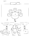
control modules 1 are each assigned to agroup controller 2 according toFig. 1 . In terms of hardware, thegroup controller 2 has an identical structure to thecontrol modules 1. However, only therespective group controller 2 is able to interact with aserver 4 via a long-range connection 3. This is typically access to a local cellular network provider, via which the server is then kept reachable based on IP-WAN. Communication between the server and the group controllers can be carried out using a common Internet protocol (TCP/IP), for example. - Inside a
group 7, the control modules communicate with one another via short-range connections 6. This is preferably communication based on a mesh network on the IEEE 802.15.4 standard, for example ZigBee. - The
respective groups 7 ofcontrol modules group controllers 2 which can see one another via their IP address on the Internet. The information relating to which control module can communicate with which control module and how this module can communicate is stipulated on the server side and is achieved in a cross-group manner, for example for the case of short-range communication, by means of a multiplexing unit of each control module, in particular. - A server for operating a network according to the invention can also, in addition to connecting one or
more groups 7 ofcontrol modules Fig. 2 ). The latter in turn manages a number of luminaire controllers 9. The segment controller 8 is connected via aninterface 11 which can be used to interchange data with theserver 4. In addition to connecting the plurality ofgroups 7 via possibly afurther interface 12, theserver 4 may operate data interchange with a long-range network operator 14 again via a further interface (API) 13. - A
database 16 which interacts with different operating modules (clients) 17 generally runs on the server itself. A user can access the server and its programs for operating and controlling the luminaire groups via agraphical user interface 18. -
Fig. 3 gives a shortened description of the sequence of setting up a network of street lights. After a number of control modules have been installed in afirst phase 19 on street lights, the control modules will scan their environment in asecond phase 20 which is either started on the server side or starts independently and will transmit the respective environmental information and any further luminaire-specific and control module-specific information to the server. This can be carried out either directly under roaming conditions with a first provider or possibly with a further local network provider predefined by the server after the respective control modules have been registered for the first time. After the environmental information and further information has been transmitted by the respective control modules of the street lights, the control modules are determined and allocated (phase 21) in groups and the group controller is determined and allocated. At the PAN level, the network can be set up on the basis of the standard used, for example dynamically. After the respective group controllers have transmitted a data signal to the server relating to the successful realization of internal group communication, the system will change to acontrol mode 22. - Assuming that a further number of new control modules, which can be predefined on the server side, have been installed, the process can be carried out again according to the
feedback loop 23. - According to another exemplary embodiment of the invention according to
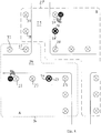
Fig. 4 , a plurality of luminaires withrespective control modules 23 and 23' are arranged along aroad 24. The luminaires belong to a group of luminaires or control modules A which was predefined on the server side. Like a group B, the group A is marked by dashedlines 26 and 27, respectively. Luminaires with associatedcontrol modules 28 and 28' which line across street 29 opening into theroad 24 belong to group B. Innerblack circles respective control modules road - For example, if an approaching car is detected using the
control module 23 of a street light, which is provided with the sensor S1, the information is shared in group A, the light in group A is turned up usingcontrol modules 23 and 23' and this information or the information relating to the approaching car is transmitted to the group controller 28' in group B via the group controller 23'. The brightness is then also adapted in the relevant luminaires ofcontrol modules 28 and 28', that is to say the luminaires selected on the server side, in group B. Alternatively, thecontrol module 23 provided with the sensor S1 could also communicate directly with the group controller 28' in group B or with afurther control module 28 which is assigned to said controller 28' and belongs to one of the street lights, whereupon the information is shared in the network and a corresponding reaction is given in group B. - The respective control modules and therefore the associated street light lights can be assigned on the server side to a first group which is intended to be supplied with an item of sensor information from a sensor in an adjacent group and which is then used to forward information in a cross-group manner. Corresponding input masks are available for this purpose on the server side, in particular.
- A control module according to the invention which can be used to implement the method described above can preferably be placed onto a luminaire head, for example of a street light, as a separate unit (cf.
Fig. 7 ). The important parts of a control module which can be externally attached are disclosed in more detail inFig. 5 . In the exploded illustration illustrated there, the control module comprises anupper housing part 33 and alower housing part 34. The lower housing part can be fastened to a base to be arranged on the top side of the light via a seal 35. The connection to the base is effected usingcontacts 37 to be twisted in a bayonet-like manner. Thecontacts 37 are fastened in thehousing 34, on the one hand, and bear a central printedcircuit board unit 38, on the other hand. A controller 39, short-range and long-range communication modules and anacceleration sensor unit 41 for detecting seismic waves, in particular, are present, inter alia, on said printed circuit board unit. - An RFID reader which can be introduced into a base on the luminaire housing side in order to be able to receive luminaire-specific data from an RFID transponder in the near field is not illustrated.
- The depiction according to
Fig. 6 illustrates a road system having a plurality ofroads 42 of a length of several hundred metres. These roads are lined by a multiplicity of street light lights 43 with respective control modules. The control modules are each provided with sensors for detecting seismic waves. These may be simple acceleration sensors, on the one hand. Alternatively, more complicated seismometers may also be used in a manner integrated in the street light. The data emanating from the acceleration sensors, which are preferably integrated in the control module directly inside the housing, can be transmitted to the server via the group controller and its long-range communication module. As a result, it is possible to detect seismic waves even in the case of relatively inaccurate sensors on account of the multiplicity of signals transmitted by said sensors and to analyse them in a spatially and temporally resolved manner in the server on the basis of the geocoordinates to be concomitantly transmitted by the control modules and the group controller. This results in a comparatively accurate depiction of the earthquake progress even with a poor resolution of the P waves and/or S waves. Accordingly, information relating to the epicentre of the earthquake can also be extracted from the information. This can happen either on the server of the network or on a special server assigned to an earthquake centre. Accordingly, a subsequent tsunami warning or else an earthquake warning may also result via control of the luminaires, for example by emitting light signals previously disclosed to the population. These may be, for example, wave-like light signals of alternating and propagating luminosi-ties which run along the road. - By integrating a street light according to
Fig. 7 in the ground and permanently arranging and connecting said street light to the ground using a layer of lean concrete 44, afoundation pipe 45 anddense filling material 46, for example, acceleration sensors arranged in the control module in or on theluminaire head 48 can effectively pick up the seismic waves propagating in the soil or along its surface via the mast 49. Alternatively or additionally, a more finely resolvingseismometer 52 may also be arranged in the base of the mast 49, which seismometer is connected to thecontrol module 2 via a data line (not shown). A great advantage of the system is the evaluation of a multiplicity of sensors which are distributed over a large area, which evaluation can be carried out virtually at the same time and enables an analysis in order to detectseismic waves 50 illustrated using dashed lines inFig. 6 . At the same time, an information system which can be used to simultaneously inform a multiplicity of road users is possible.
Claims (31)
- Method for operating a network of luminaires, wherein the network of luminaires comprises a plurality of luminaires, in particular street lights, a plurality of control modules (1, 2, 23, 23', 28, 28') and a server (4), wherein each of said plurality of control modules is assigned to a respective one of said plurality of luminaires and comprises:- a long-range communication module,- a short-range communication module,- a geocoordinates module,- a controller (39), and- a control output for controlling a driver of the respective luminaire,the control output being adapted to output control signals for the driver of a luminous means of the respective luminaire,
wherein the respective long-range communication module of each control module is adapted to reach said server (4),
the method including the step of dividing the plurality of control modules (1, 2, 23, 23', 28, 28') into at least one group (A, B) of control modules,
characterized in that said division into at least one group (A,B) of control modules is done in order to set up the network on the basis of environmental, luminaire and/or control module information provided by the control modules,
characterized in that the method further comprises the following steps:• selecting by the server (4) one of the control modules in each of said at least one group (A, B) of control modules as the group controller (2, 23', 28'),• forming a short-range network of control modules (1, 23, 28) within each of said at least one group (A, B) via the respective short-range communication modules,the control modules in each of said at least one group (A, B) communicating by means of their short-range communication modules,
wherein in the normal operating state of the network of luminaires, only each group controller (2, 23', 28') transmits via the respective long-range communication module to the server (4), at least one of its own environmental, luminaire and control module information, and at least one of the environmental, luminaire and control module information received from the control modules (1, 23, 28) of its respective group via their short-range communication module,
wherein said normal operating state is a control mode of the network of luminaires, in which each of said plurality of control modules is assigned to a respective one of said at least one group (A, B) of control modules and perform the control of the respective luminaire, and
wherein, after successfully setting up the short-range network inside a respective one of the at least one group (A, B) of control modules, the respective group controller (2, 23', 28') reports the successful set up to the server (4). - Method according to claim 1, wherein each of the plurality of control modules further comprises a near-field communication module.
- Method according to claim 1 or 2, wherein at least one of the plurality of control modules further comprises at least one sensor (41).
- Method according to any one of the preceding claims, wherein said short-range network is a mesh network.
- Method according to one of the preceding claims, wherein when any of the plurality of control modules (1, 2, 23, 23', 28, 28') starts up for the first time the following steps are carried out by said respective control module:• acquiring geoinformation using the geocoordinates module,• registering with a network provider (14) via the respective long-range communication module of said respective control module, and• transmitting the acquired geoinformation to the server (4) with at least one of control module and luminaire information.
- Method according to claim 5, wherein to start up a control module for the first time a voltage is applied to said control module.
- Method according to claim 5 or 6, wherein registering with the network provider (14) is done under roaming conditions.
- Method according to any one of the claims 5 to 7, further comprising, after transmitting said acquired geoinformation with at least one of control module and luminaire information relating to said respective control module to the server (4), transmitting to said respective control module network provider access data specific to a locally present long-range network.
- Method according to any of claims 5 to 8, further comprising the step of: activating, suspending or deactivating individual control modules (1, 2, 23, 23', 28, 28') on the server side via an application programming interface (13) to the network provider (14).
- Method according to any of claims 1 to 4, further comprising the step of: activating, suspending or deactivating individual control modules (1, 2, 23, 23', 28, 28') on the server side via an application programming interface (13) to a network provider (14).
- Method according to any one of claims 5 to 10, further comprising the step of: transmitting, to the network provider (14) via an interface, information relating to the control modules other than the group controllers to be suspended or deactivated in terms of their long-range communication.
- Method according to any one of the preceding claims, wherein at least some of the plurality of control modules (1, 2, 23, 23', 28, 28') have an electronic SIM wherein the method further comprises making provider access data available via firmware to those control modules which have an electronic SIM.
- Method according to any one of the preceding claims, further comprising the step of: transmitting an item of information from the server (4) to the control modules other that the group controllers, and wherein, in accordance with said item of information, these control modules (1, 2, 23, 23', 28, 28') do not carry out any long-range communication in the normal operating state.
- Method according to any one of the preceding claims, further comprising the step of: providing, using the server (4), the control modules (1, 2, 23, 23', 28, 28') in a respective group of said at least one group (A, B) of control modules with information relating to adjacent control modules in the same respective group.
- Method according to any one of the preceding claims, wherein, after voltage is applied to a respective one of said plurality of control modules said respective control module operates its respective luminaire with different brightnesses over predefined intervals of time.
- Method according to any one of the preceding claims, further comprising the step of: receiving, in at least one of said plurality of control modules (1, 2, 23, 23', 28, 28') from the server (4), a parameter set for operating the respective luminaire of said at least one control module after said at least one control module has been installed for the first time or installed again.
- Method according to any one of the preceding claims, wherein the control modules (1,2,23,23',28,28') in each group of said at least one group (A,B) of control modules are supplied with software updates via software transmitted to the respective group controller of each respective group by the server (4).
- Method according to any one of the preceding claims, further comprising the step of receiving, in at least one of said plurality of control modules (1, 2, 23, 23', 28, 28') from the server (4), new controller firmware.
- Method according to any one of the preceding claims, wherein, after being switched on for the first time, the control modules (1,2,23,23',28,28') of a respective one of the at least one group (A, B) of control modules automatically scan the respective short-range network for further control modules.
- Method according to any one of the preceding claims, further comprising the steps of:• providing an information carrier arranged on a part of one of the plurality of luminaires,• receiving luminaire information at said information carrier, and• reading said information carrier in an automated and/or triggered manner.
- Method according to claim 20, further comprising reading said information carrier using a near-field sensor of the respective control module of said one of the plurality of luminaires.
- Method according to claim 20 or 21, further comprising linking, on the server side, the luminaire information of said one of the plurality of luminaires to an inventory list, the content of which can at least partially be displayed if one of the parts of said one of the plurality of luminaires fails.
- Method according to any one of the preceding claims, wherein each control module of said plurality of control modules (1, 2, 23, 23', 28, 28') transmits to the server (4) at least one of: data relating to its respective unique identifier in the respective short-range network, its respective IP address in a long-range network, respective luminaire information, data relating to up to 50 adjacent control modules in the respective short-range network, including any unique identifier, and the connection quality belonging to the adjacent control modules.
- Method according to any one of the preceding claims, wherein each group of the at least one group (A, B) of control modules is assigned the same number as or fewer than a predefinable number of control modules, the predefinable number being preferably 200.
- Method according to any one of the preceding claims, wherein said selection by the server (4) of one of the control modules in each of said at least one group (A, B) as the respective group controller is made in an automated manner on the basis of fuzzy control strategies.
- Method according to claim 25, wherein said selection is made taking into account rules for at least one of:• the ratio of active to inactive control modules,• a number of network disturbances,• network changes,• change in the connection quality in the respective short-range network, and• the failure and replacement of active group controllers.
- Method according to claim 26, wherein said rules are mapped and linked using an artificial intelligence, Al, system.
- Method according to any one of the preceding claims, further comprising performing one of: suspending and deactivating a control module of said plurality of control modules (1, 2, 23, 23', 28, 28') in an automated manner on the basis of fuzzy control strategies.
- Method according to any one of the preceding claims, comprising a step of acquisition of environmental information relating to a respective short-range network and wherein the acquisition of environmental information relating to a respective short-range network and communication in said respective short-range network for the purpose of normal operation are carried out in different frequency bands of said respective short-range network.
- Method according to claim 29, wherein the same antenna is used for said different frequency bands.
- Network of luminaires comprising a plurality of luminaires, in particular street lights, a plurality of control modules (1, 2, 23, 23', 28, 28') and a server (4), wherein each of said plurality of control modules is assigned to a respective one of said plurality of luminaires and comprises:- a long-range communication module,- a short-range communication module,- a geocoordinates module,- a controller (39), and- a control output for controlling a driver of the respective luminaire, the control output being configured to output control signals for the driver of a luminous means of the respective luminaire,
wherein the respective long-range communication module of each control module is adapted to reach said server (4),
the network of luminaires being characterized in that- said plurality of control modules is divided in at least one group (A, B) of control modules in order to set up the network on the basis of at least one of environmental, luminaire and control module information provided by the control modules;- the server (4) is adapted to select one of the control modules in each group (A, B) as the group controller (2, 23', 28');- the respective short-range communication modules form a short-range network within each of said at least one group (A, B) of control modules (1, 2, 23, 23', 28, 28'), the respective control modules within each group (A, B) being configured to communicate with one another via their respective short-range communication modules,- each of said at least one group (A, B) of control modules comprising a respective group controller (2, 23', 28'), each group controller (2, 23', 28') being configured to communicate with other control modules (1, 23, 28) in the respective group (A, B) by means of its respective short-range communication module,the control modules in a respective group other than the respective group controller (2, 23', 28') being configured to transmit, to the respective group controller (2, 23', 28') of their group, via their short-range communication modules, at least one of their own environmental, luminaire and control module information,
wherein, in the normal operating state of the network of luminaires, only the respective group controller (2, 23', 28') of each of said at least one group (A, B) is configured to transmit via the respective long-range communication module to the server (4), at least one of its own environmental, luminaire and control module information, and at least one of environmental, luminaire and control module information received from the other control modules (1, 23, 28) of the respective group via their short-range communication module,
said normal operating state being a control mode of the network of luminaires, in which each of said plurality of modules is assigned to a respective one of said at least one group and perform the control of the respective luminaire,
wherein each group controller (2, 23', 28') is configured for, after successfully set up of the respective short-range network inside its respective group, reporting this successful set up to the server (4).
Priority Applications (15)
| Application Number | Priority Date | Filing Date | Title |
|---|---|---|---|
| PL14192579T PL3018978T3 (en) | 2014-11-10 | 2014-11-10 | METHOD OF CONFIGURING AND ACTIVATING NETWORKS OF LUMINAIRES |
| PT141925792T PT3018978T (en) | 2014-11-10 | 2014-11-10 | METHOD FOR CONFIGURING AND OPERATING A NETWORK OF PUBLIC LIGHTING POINTS |
| EP14192579.2A EP3018978B1 (en) | 2014-11-10 | 2014-11-10 | Method for setting up and operating a network of luminaires |
| ES14192579T ES2863728T3 (en) | 2014-11-10 | 2014-11-10 | Method to configure and operate a network of luminaires |
| BE2015/5020A BE1023601B1 (en) | 2014-11-10 | 2015-01-13 | Method for establishing and managing a lamp network |
| PCT/EP2015/076144 WO2016075105A1 (en) | 2014-11-10 | 2015-11-10 | Method for setting up and operating a network of luminaires |
| KR1020177015499A KR20170092569A (en) | 2014-11-10 | 2015-11-10 | Method for setting up and operating a network of luminaires |
| AU2015345208A AU2015345208B2 (en) | 2014-11-10 | 2015-11-10 | Method for setting up and operating a network of luminaires |
| JP2017524463A JP2017533565A (en) | 2014-11-10 | 2015-11-10 | Method for configuring and operating a luminaire network |
| CN201580066264.XA CN107006106B (en) | 2014-11-10 | 2015-11-10 | Method for establishing and operating a lighting device network |
| US15/525,265 US10212789B2 (en) | 2014-11-10 | 2015-11-10 | Method for setting up and operating a network of luminaires |
| ZA2017/03844A ZA201703844B (en) | 2014-11-10 | 2017-06-05 | Method for setting up and operating a network of luminaires |
| US16/275,454 US10806012B2 (en) | 2014-11-10 | 2019-02-14 | Method for setting up and operating a network of luminaires |
| US17/068,680 US11497105B2 (en) | 2014-11-10 | 2020-10-12 | Method for setting up and operating a network of luminaires |
| US17/813,250 US11723139B2 (en) | 2014-11-10 | 2022-07-18 | Method for setting up and operating a network of luminaires |
Applications Claiming Priority (1)
| Application Number | Priority Date | Filing Date | Title |
|---|---|---|---|
| EP14192579.2A EP3018978B1 (en) | 2014-11-10 | 2014-11-10 | Method for setting up and operating a network of luminaires |
Publications (2)
| Publication Number | Publication Date |
|---|---|
| EP3018978A1 EP3018978A1 (en) | 2016-05-11 |
| EP3018978B1 true EP3018978B1 (en) | 2021-01-20 |
Family
ID=51870906
Family Applications (1)
| Application Number | Title | Priority Date | Filing Date |
|---|---|---|---|
| EP14192579.2A Active EP3018978B1 (en) | 2014-11-10 | 2014-11-10 | Method for setting up and operating a network of luminaires |
Country Status (12)
| Country | Link |
|---|---|
| US (4) | US10212789B2 (en) |
| EP (1) | EP3018978B1 (en) |
| JP (1) | JP2017533565A (en) |
| KR (1) | KR20170092569A (en) |
| CN (1) | CN107006106B (en) |
| AU (1) | AU2015345208B2 (en) |
| BE (1) | BE1023601B1 (en) |
| ES (1) | ES2863728T3 (en) |
| PL (1) | PL3018978T3 (en) |
| PT (1) | PT3018978T (en) |
| WO (1) | WO2016075105A1 (en) |
| ZA (1) | ZA201703844B (en) |
Families Citing this family (19)
| Publication number | Priority date | Publication date | Assignee | Title |
|---|---|---|---|---|
| ES2863728T3 (en) * | 2014-11-10 | 2021-10-11 | Schreder | Method to configure and operate a network of luminaires |
| EP3412117B1 (en) * | 2016-02-05 | 2020-08-19 | Schreder | Lamp control module consisting of base and control parts, communicating via nfc |
| JP6921546B2 (en) * | 2017-02-16 | 2021-08-18 | キヤノン株式会社 | Management devices, mobile terminals, their methods, and programs |
| JP7241076B2 (en) * | 2017-12-05 | 2023-03-16 | シグニファイ ホールディング ビー ヴィ | Systems, methods and apparatus for distributed detection of luminaire anomalies |
| US12108327B2 (en) | 2018-01-09 | 2024-10-01 | Signify Holding, B.V. | Dual-mode electronic device |
| AU2019200218B2 (en) * | 2018-01-26 | 2020-11-19 | Techtronic Cordless Gp | An electrical apparatus, a power system, a power tool, a network of power tools and a power tool controller |
| US11159614B2 (en) | 2019-01-23 | 2021-10-26 | Samsung Electronics Co., Ltd. | Method and apparatus for managing data in a network based on swarm intelligence |
| ES2935794T3 (en) * | 2019-03-18 | 2023-03-10 | Signify Holding Bv | Diagnosing a problem that occurs when controlling a lighting fixture based on lighting fixture grouping information |
| NL2023556B1 (en) | 2019-07-23 | 2021-02-10 | Schreder Sa | Communication device |
| US11295253B2 (en) | 2019-12-03 | 2022-04-05 | Copperleaf Technologies Inc. | Method and apparatus for asset management |
| NL2025706B1 (en) | 2020-05-29 | 2022-01-13 | Schreder Sa | Luminaire system and network of luminaire systems for disinfecting areas |
| NL2025801B1 (en) | 2020-06-10 | 2022-02-16 | Schreder Sa | Power cutoff message handling |
| WO2022017908A1 (en) * | 2020-07-23 | 2022-01-27 | Signify Holding B.V. | Intelligent lighting control system |
| EP4211906B1 (en) | 2020-09-07 | 2024-08-07 | Signify Holding B.V. | A method of and a system for transmitting a trigger message in a network of operatively interconnected node devices |
| JP7565497B2 (en) * | 2020-10-23 | 2024-10-11 | パナソニックIpマネジメント株式会社 | Equipment Control System |
| US20240107419A1 (en) | 2020-11-02 | 2024-03-28 | Signify Holding B.V. | A method of and a node device for relaying a message in a network of operatively interconnected node devices |
| CN116458111A (en) | 2020-11-05 | 2023-07-18 | 昕诺飞控股有限公司 | Method, configurator and system for configuring a plurality of operatively interconnected node devices in a network |
| WO2022266522A1 (en) * | 2021-06-18 | 2022-12-22 | Lutron Technology Company Llc | Sensor for measuring environmental conditions in a user environment |
| NL2029131B1 (en) * | 2021-09-06 | 2023-03-21 | Summa Ip B V | Illumination assembly communication |
Citations (10)
| Publication number | Priority date | Publication date | Assignee | Title |
|---|---|---|---|---|
| EP2262350A1 (en) | 2009-06-10 | 2010-12-15 | iLEDs GmbH | Lighting unit, network of lighting units and method for controlling the light intensity of a lighting network comprising at least one lighting unit |
| US8010319B2 (en) | 2005-09-12 | 2011-08-30 | Abl Ip Holding Llc | Light management system having networked intelligent luminaire managers |
| WO2011123920A1 (en) | 2010-04-07 | 2011-10-13 | Carmanah Technologies Corp. | Distributed control intelligent lighting array |
| US20120143383A1 (en) | 2007-02-02 | 2012-06-07 | Inovus Solar, Inc. | Energy-efficient utility system utilizing solar-power |
| US20120147604A1 (en) * | 2010-12-14 | 2012-06-14 | Todd Farmer | Gimbaled LED Array Module |
| US20120286770A1 (en) | 2011-05-11 | 2012-11-15 | Schreder | Lighting systems |
| US20130044488A1 (en) | 2011-08-17 | 2013-02-21 | G. Albert Hreish | Combination Lamp and Wireless Network Access System |
| US20130057158A1 (en) | 2010-03-01 | 2013-03-07 | Led Roadway Lighting Ltd. | Gps-based streetlight wireless command and control system |
| US8820952B2 (en) | 2012-01-17 | 2014-09-02 | Cimcon Lighting, Inc. | Streetlight controllers |
| WO2015000803A1 (en) | 2013-07-05 | 2015-01-08 | Koninklijke Philips N.V. | A method for operating a communication device in a communication network, a communication device, a luminaire equipped with such communication device |
Family Cites Families (25)
| Publication number | Priority date | Publication date | Assignee | Title |
|---|---|---|---|---|
| JP4177547B2 (en) * | 2000-11-27 | 2008-11-05 | 松下電工株式会社 | Environmental control system |
| CN101505569A (en) * | 2009-03-25 | 2009-08-12 | 李刚 | LED road lamp computer management system and apparatus |
| US10429869B2 (en) * | 2011-02-16 | 2019-10-01 | Kortek Industries Pty Ltd | Wireless power, light and automation control |
| JP2012230780A (en) * | 2011-04-25 | 2012-11-22 | Sharp Corp | Sensor system |
| US9801261B2 (en) * | 2012-01-05 | 2017-10-24 | Bright Light Systems, Inc. | Systems and methods for providing high-mast lighting |
| JP2013120749A (en) * | 2012-02-15 | 2013-06-17 | Sharp Corp | Lighting system, remote controller, lighting control system, control method, program, and recording medium |
| US8755039B2 (en) * | 2012-05-03 | 2014-06-17 | Abl Ip Holding Llc | Lighting devices with sensors for detecting one or more external conditions and networked system using such devices |
| US9125255B2 (en) * | 2012-05-03 | 2015-09-01 | Abl Ip Holding Llc | Networked architecture for system of lighting devices having sensors, for intelligent applications |
| US20150213415A1 (en) * | 2012-07-10 | 2015-07-30 | Koninklijke Philips N.V | System and method for providing adaptive measurement and coordinated maintenance of outdoor lighting systems |
| US9137879B2 (en) * | 2012-08-01 | 2015-09-15 | Abl Ip Holding Llc | Networked system of intelligent lighting devices with sharing of processing resources of the devices with other entities |
| US9832833B1 (en) * | 2015-05-27 | 2017-11-28 | Kuna Systems Corporation | Smart lighting by outdoor wall-mounted or ceiling mounted light fixtures and/or connected light bulbs |
| US9208676B2 (en) * | 2013-03-14 | 2015-12-08 | Google Inc. | Devices, methods, and associated information processing for security in a smart-sensored home |
| TW201436642A (en) * | 2013-03-06 | 2014-09-16 | Wavien Inc | Wireless control light source |
| EP3664583B1 (en) * | 2013-03-18 | 2024-11-27 | Signify Holding B.V. | Methods and apparatus for information management and control of outdoor lighting networks |
| US8928232B2 (en) * | 2013-05-28 | 2015-01-06 | Abl Ip Holding Llc | Lighting network with autonomous commissioning |
| US9629220B2 (en) * | 2013-08-05 | 2017-04-18 | Peter Panopoulos | Sensor-based controllable LED lighting system with repositionable components and method |
| JP6359103B2 (en) * | 2013-09-04 | 2018-07-18 | コーニンクレッカ フィリップス エヌ ヴェKoninklijke Philips N.V. | System for remote control of controllable devices |
| WO2015054225A1 (en) * | 2013-10-07 | 2015-04-16 | Google Inc. | Smart-home hazard detector providing non-alarm status signals at opportune moments |
| US9560727B2 (en) * | 2014-10-06 | 2017-01-31 | Fabriq, Ltd. | Apparatus and method for creating functional wireless lighting groups |
| ES2863728T3 (en) * | 2014-11-10 | 2021-10-11 | Schreder | Method to configure and operate a network of luminaires |
| US9532434B2 (en) * | 2014-12-30 | 2016-12-27 | Google Inc. | Systems and methods of determining a type and feature set of a light source, and the control thereof |
| WO2016155021A1 (en) * | 2015-04-03 | 2016-10-06 | 绿仕科技控股有限公司 | Environmental control system |
| US10314146B1 (en) * | 2015-08-28 | 2019-06-04 | Steven P Wilburn | Mesh network of lighting devices having communication and control functions |
| US10211660B2 (en) * | 2016-02-08 | 2019-02-19 | Cree, Inc. | LED lighting device with adaptive profiles for controlling power consumption |
| CA3017063C (en) * | 2016-03-08 | 2021-05-18 | Eaton Intelligent Power Limited | Controllers for interconnected lighting devices |
-
2014
- 2014-11-10 ES ES14192579T patent/ES2863728T3/en active Active
- 2014-11-10 PT PT141925792T patent/PT3018978T/en unknown
- 2014-11-10 EP EP14192579.2A patent/EP3018978B1/en active Active
- 2014-11-10 PL PL14192579T patent/PL3018978T3/en unknown
-
2015
- 2015-01-13 BE BE2015/5020A patent/BE1023601B1/en active
- 2015-11-10 WO PCT/EP2015/076144 patent/WO2016075105A1/en not_active Ceased
- 2015-11-10 US US15/525,265 patent/US10212789B2/en active Active
- 2015-11-10 CN CN201580066264.XA patent/CN107006106B/en active Active
- 2015-11-10 KR KR1020177015499A patent/KR20170092569A/en not_active Withdrawn
- 2015-11-10 JP JP2017524463A patent/JP2017533565A/en not_active Ceased
- 2015-11-10 AU AU2015345208A patent/AU2015345208B2/en active Active
-
2017
- 2017-06-05 ZA ZA2017/03844A patent/ZA201703844B/en unknown
-
2019
- 2019-02-14 US US16/275,454 patent/US10806012B2/en active Active
-
2020
- 2020-10-12 US US17/068,680 patent/US11497105B2/en active Active
-
2022
- 2022-07-18 US US17/813,250 patent/US11723139B2/en active Active
Patent Citations (10)
| Publication number | Priority date | Publication date | Assignee | Title |
|---|---|---|---|---|
| US8010319B2 (en) | 2005-09-12 | 2011-08-30 | Abl Ip Holding Llc | Light management system having networked intelligent luminaire managers |
| US20120143383A1 (en) | 2007-02-02 | 2012-06-07 | Inovus Solar, Inc. | Energy-efficient utility system utilizing solar-power |
| EP2262350A1 (en) | 2009-06-10 | 2010-12-15 | iLEDs GmbH | Lighting unit, network of lighting units and method for controlling the light intensity of a lighting network comprising at least one lighting unit |
| US20130057158A1 (en) | 2010-03-01 | 2013-03-07 | Led Roadway Lighting Ltd. | Gps-based streetlight wireless command and control system |
| WO2011123920A1 (en) | 2010-04-07 | 2011-10-13 | Carmanah Technologies Corp. | Distributed control intelligent lighting array |
| US20120147604A1 (en) * | 2010-12-14 | 2012-06-14 | Todd Farmer | Gimbaled LED Array Module |
| US20120286770A1 (en) | 2011-05-11 | 2012-11-15 | Schreder | Lighting systems |
| US20130044488A1 (en) | 2011-08-17 | 2013-02-21 | G. Albert Hreish | Combination Lamp and Wireless Network Access System |
| US8820952B2 (en) | 2012-01-17 | 2014-09-02 | Cimcon Lighting, Inc. | Streetlight controllers |
| WO2015000803A1 (en) | 2013-07-05 | 2015-01-08 | Koninklijke Philips N.V. | A method for operating a communication device in a communication network, a communication device, a luminaire equipped with such communication device |
Non-Patent Citations (11)
| Title |
|---|
| ANONYMOUS: "CIMCON Lighting Announces GPS Support for Its Wireless Outdoor Lighting Controllers", CIMCON, 11 March 2014 (2014-03-11), pages 1, XP055194551 |
| ANONYMOUS: "Grafische Oberfläche V3.7 - LUXMATE-Windows-Software zur Visualisierung, Überwachung und Verwaltung einer LUXMATE-Anlage", ZUMTOBEL, 2006, pages 1 - 112, XP055860855 |
| ANONYMOUS: "LightinGale-Remotely Monitor and Control Street Lights", CIMCON SOFTWARE INDIA, 1 January 2009 (2009-01-01), pages 1 - 2, XP055204539 |
| ANONYMOUS: "LUXMATE LITENET", ZUMTOBEL, June 2012 (2012-06-01), pages 1 - 44, XP055665817 |
| ANONYMOUS: "Manual TELEA Central Management", THORN LIGHTING, pages 1 - 44, XP055860875 |
| ANONYMOUS: "Telea Outdoor Lighting Controls", THORN LIGHTING, June 2009 (2009-06-01), pages 1 - 24, XP055860704 |
| ANONYMOUS: "Telea Outdoor Lighting Controls, Wide area management for ultimate efficiency", THORN LIGHTING, April 2006 (2006-04-01), pages 1 - 28, XP055860711 |
| ANONYMOUS: "TELEA-CMEG Zentraler Server mit GSM-Modem", THORN LIGHTING |
| ANONYMOUS: "User Manual TELEACombox Controller Software Thorn Lighting", USER MANUAL TELEACOMBOX CONTROLLER SOFTWARE THORN LIGHTING, pages 1 - 86, XP055860868 |
| CIMCON SOFTWARE INDIA: "LightingGale - Remotely Monitor and Control Street Lights", 1 January 2009 (2009-01-01), pages 1 - 2, XP055204539, Retrieved from the Internet <URL:http://www.cimconautomation.com/power/street_light_cm.htm> [retrieved on 20150724] * |
| CIMCON: "CIMCON Lighting Announces GPS Support for Its Wireless Outdoor Lighting Controllers", PRESS RELEASES | WIRELESS LIGHTING | CIMCON LIGHTING, INC, 11 March 2014 (2014-03-11), XP055194551, Retrieved from the Internet <URL:http://www.cimconlighting.com/03112014.htm> [retrieved on 20150609] * |
Also Published As
| Publication number | Publication date |
|---|---|
| CN107006106A (en) | 2017-08-01 |
| BE1023601A1 (en) | 2017-05-12 |
| US10806012B2 (en) | 2020-10-13 |
| JP2017533565A (en) | 2017-11-09 |
| WO2016075105A1 (en) | 2016-05-19 |
| AU2015345208A1 (en) | 2017-06-29 |
| PL3018978T3 (en) | 2021-09-27 |
| ES2863728T3 (en) | 2021-10-11 |
| PT3018978T (en) | 2021-04-20 |
| ZA201703844B (en) | 2019-09-25 |
| US20190182938A1 (en) | 2019-06-13 |
| KR20170092569A (en) | 2017-08-11 |
| US20220353977A1 (en) | 2022-11-03 |
| US20180288855A1 (en) | 2018-10-04 |
| US10212789B2 (en) | 2019-02-19 |
| BE1023601B1 (en) | 2017-05-12 |
| US11497105B2 (en) | 2022-11-08 |
| AU2015345208B2 (en) | 2021-05-13 |
| US11723139B2 (en) | 2023-08-08 |
| US20210045222A1 (en) | 2021-02-11 |
| CN107006106B (en) | 2019-03-22 |
| EP3018978A1 (en) | 2016-05-11 |
Similar Documents
| Publication | Publication Date | Title |
|---|---|---|
| US11723139B2 (en) | Method for setting up and operating a network of luminaires | |
| AU2021203024B2 (en) | Control module for controlling a light, particularly a street light, and network of lights | |
| US11552826B2 (en) | Method for the operation and expansion of a network of lights | |
| EP3018497B1 (en) | Method for detecting earthquakes and locating epicentres by means of a network of lights. | |
| EP3018980B1 (en) | Method for operating and controlling a network of lights |
Legal Events
| Date | Code | Title | Description |
|---|---|---|---|
| PUAI | Public reference made under article 153(3) epc to a published international application that has entered the european phase |
Free format text: ORIGINAL CODE: 0009012 |
|
| AK | Designated contracting states |
Kind code of ref document: A1 Designated state(s): AL AT BE BG CH CY CZ DE DK EE ES FI FR GB GR HR HU IE IS IT LI LT LU LV MC MK MT NL NO PL PT RO RS SE SI SK SM TR |
|
| AX | Request for extension of the european patent |
Extension state: BA ME |
|
| STAA | Information on the status of an ep patent application or granted ep patent |
Free format text: STATUS: REQUEST FOR EXAMINATION WAS MADE |
|
| 17P | Request for examination filed |
Effective date: 20161031 |
|
| RBV | Designated contracting states (corrected) |
Designated state(s): AL AT BE BG CH CY CZ DE DK EE ES FI FR GB GR HR HU IE IS IT LI LT LU LV MC MK MT NL NO PL PT RO RS SE SI SK SM TR |
|
| STAA | Information on the status of an ep patent application or granted ep patent |
Free format text: STATUS: EXAMINATION IS IN PROGRESS |
|
| 17Q | First examination report despatched |
Effective date: 20180821 |
|
| GRAP | Despatch of communication of intention to grant a patent |
Free format text: ORIGINAL CODE: EPIDOSNIGR1 |
|
| STAA | Information on the status of an ep patent application or granted ep patent |
Free format text: STATUS: GRANT OF PATENT IS INTENDED |
|
| INTG | Intention to grant announced |
Effective date: 20190621 |
|
| GRAJ | Information related to disapproval of communication of intention to grant by the applicant or resumption of examination proceedings by the epo deleted |
Free format text: ORIGINAL CODE: EPIDOSDIGR1 |
|
| STAA | Information on the status of an ep patent application or granted ep patent |
Free format text: STATUS: EXAMINATION IS IN PROGRESS |
|
| GRAP | Despatch of communication of intention to grant a patent |
Free format text: ORIGINAL CODE: EPIDOSNIGR1 |
|
| STAA | Information on the status of an ep patent application or granted ep patent |
Free format text: STATUS: GRANT OF PATENT IS INTENDED |
|
| INTC | Intention to grant announced (deleted) | ||
| INTG | Intention to grant announced |
Effective date: 20191122 |
|
| GRAJ | Information related to disapproval of communication of intention to grant by the applicant or resumption of examination proceedings by the epo deleted |
Free format text: ORIGINAL CODE: EPIDOSDIGR1 |
|
| STAA | Information on the status of an ep patent application or granted ep patent |
Free format text: STATUS: EXAMINATION IS IN PROGRESS |
|
| REG | Reference to a national code |
Ref country code: DE Ref legal event code: R079 Ref document number: 602014074349 Country of ref document: DE Free format text: PREVIOUS MAIN CLASS: H05B0037020000 Ipc: H05B0047190000 |
|
| INTC | Intention to grant announced (deleted) | ||
| GRAP | Despatch of communication of intention to grant a patent |
Free format text: ORIGINAL CODE: EPIDOSNIGR1 |
|
| STAA | Information on the status of an ep patent application or granted ep patent |
Free format text: STATUS: GRANT OF PATENT IS INTENDED |
|
| RIC1 | Information provided on ipc code assigned before grant |
Ipc: H05B 47/19 20200101AFI20200504BHEP Ipc: H04W 84/18 20090101ALN20200504BHEP Ipc: H04W 40/24 20090101ALN20200504BHEP |
|
| INTG | Intention to grant announced |
Effective date: 20200519 |
|
| GRAS | Grant fee paid |
Free format text: ORIGINAL CODE: EPIDOSNIGR3 |
|
| GRAA | (expected) grant |
Free format text: ORIGINAL CODE: 0009210 |
|
| STAA | Information on the status of an ep patent application or granted ep patent |
Free format text: STATUS: THE PATENT HAS BEEN GRANTED |
|
| AK | Designated contracting states |
Kind code of ref document: B1 Designated state(s): AL AT BE BG CH CY CZ DE DK EE ES FI FR GB GR HR HU IE IS IT LI LT LU LV MC MK MT NL NO PL PT RO RS SE SI SK SM TR |
|
| REG | Reference to a national code |
Ref country code: GB Ref legal event code: FG4D |
|
| REG | Reference to a national code |
Ref country code: CH Ref legal event code: EP |
|
| REG | Reference to a national code |
Ref country code: DE Ref legal event code: R096 Ref document number: 602014074349 Country of ref document: DE |
|
| REG | Reference to a national code |
Ref country code: AT Ref legal event code: REF Ref document number: 1357471 Country of ref document: AT Kind code of ref document: T Effective date: 20210215 |
|
| REG | Reference to a national code |
Ref country code: IE Ref legal event code: FG4D |
|
| REG | Reference to a national code |
Ref country code: PT Ref legal event code: SC4A Ref document number: 3018978 Country of ref document: PT Date of ref document: 20210420 Kind code of ref document: T Free format text: AVAILABILITY OF NATIONAL TRANSLATION Effective date: 20210412 |
|
| REG | Reference to a national code |
Ref country code: NL Ref legal event code: FP |
|
| REG | Reference to a national code |
Ref country code: LT Ref legal event code: MG9D |
|
| REG | Reference to a national code |
Ref country code: AT Ref legal event code: MK05 Ref document number: 1357471 Country of ref document: AT Kind code of ref document: T Effective date: 20210120 |
|
| PG25 | Lapsed in a contracting state [announced via postgrant information from national office to epo] |
Ref country code: BG Free format text: LAPSE BECAUSE OF FAILURE TO SUBMIT A TRANSLATION OF THE DESCRIPTION OR TO PAY THE FEE WITHIN THE PRESCRIBED TIME-LIMIT Effective date: 20210420 Ref country code: NO Free format text: LAPSE BECAUSE OF FAILURE TO SUBMIT A TRANSLATION OF THE DESCRIPTION OR TO PAY THE FEE WITHIN THE PRESCRIBED TIME-LIMIT Effective date: 20210420 Ref country code: LT Free format text: LAPSE BECAUSE OF FAILURE TO SUBMIT A TRANSLATION OF THE DESCRIPTION OR TO PAY THE FEE WITHIN THE PRESCRIBED TIME-LIMIT Effective date: 20210120 Ref country code: HR Free format text: LAPSE BECAUSE OF FAILURE TO SUBMIT A TRANSLATION OF THE DESCRIPTION OR TO PAY THE FEE WITHIN THE PRESCRIBED TIME-LIMIT Effective date: 20210120 Ref country code: FI Free format text: LAPSE BECAUSE OF FAILURE TO SUBMIT A TRANSLATION OF THE DESCRIPTION OR TO PAY THE FEE WITHIN THE PRESCRIBED TIME-LIMIT Effective date: 20210120 Ref country code: GR Free format text: LAPSE BECAUSE OF FAILURE TO SUBMIT A TRANSLATION OF THE DESCRIPTION OR TO PAY THE FEE WITHIN THE PRESCRIBED TIME-LIMIT Effective date: 20210421 |
|
| PG25 | Lapsed in a contracting state [announced via postgrant information from national office to epo] |
Ref country code: RS Free format text: LAPSE BECAUSE OF FAILURE TO SUBMIT A TRANSLATION OF THE DESCRIPTION OR TO PAY THE FEE WITHIN THE PRESCRIBED TIME-LIMIT Effective date: 20210120 Ref country code: LV Free format text: LAPSE BECAUSE OF FAILURE TO SUBMIT A TRANSLATION OF THE DESCRIPTION OR TO PAY THE FEE WITHIN THE PRESCRIBED TIME-LIMIT Effective date: 20210120 Ref country code: AT Free format text: LAPSE BECAUSE OF FAILURE TO SUBMIT A TRANSLATION OF THE DESCRIPTION OR TO PAY THE FEE WITHIN THE PRESCRIBED TIME-LIMIT Effective date: 20210120 Ref country code: SE Free format text: LAPSE BECAUSE OF FAILURE TO SUBMIT A TRANSLATION OF THE DESCRIPTION OR TO PAY THE FEE WITHIN THE PRESCRIBED TIME-LIMIT Effective date: 20210120 |
|
| PG25 | Lapsed in a contracting state [announced via postgrant information from national office to epo] |
Ref country code: IS Free format text: LAPSE BECAUSE OF FAILURE TO SUBMIT A TRANSLATION OF THE DESCRIPTION OR TO PAY THE FEE WITHIN THE PRESCRIBED TIME-LIMIT Effective date: 20210520 |
|
| REG | Reference to a national code |
Ref country code: ES Ref legal event code: FG2A Ref document number: 2863728 Country of ref document: ES Kind code of ref document: T3 Effective date: 20211011 |
|
| REG | Reference to a national code |
Ref country code: DE Ref legal event code: R026 Ref document number: 602014074349 Country of ref document: DE |
|
| PG25 | Lapsed in a contracting state [announced via postgrant information from national office to epo] |
Ref country code: CZ Free format text: LAPSE BECAUSE OF FAILURE TO SUBMIT A TRANSLATION OF THE DESCRIPTION OR TO PAY THE FEE WITHIN THE PRESCRIBED TIME-LIMIT Effective date: 20210120 Ref country code: EE Free format text: LAPSE BECAUSE OF FAILURE TO SUBMIT A TRANSLATION OF THE DESCRIPTION OR TO PAY THE FEE WITHIN THE PRESCRIBED TIME-LIMIT Effective date: 20210120 Ref country code: SM Free format text: LAPSE BECAUSE OF FAILURE TO SUBMIT A TRANSLATION OF THE DESCRIPTION OR TO PAY THE FEE WITHIN THE PRESCRIBED TIME-LIMIT Effective date: 20210120 |
|
| PLBI | Opposition filed |
Free format text: ORIGINAL CODE: 0009260 |
|
| PLAX | Notice of opposition and request to file observation + time limit sent |
Free format text: ORIGINAL CODE: EPIDOSNOBS2 |
|
| PG25 | Lapsed in a contracting state [announced via postgrant information from national office to epo] |
Ref country code: SK Free format text: LAPSE BECAUSE OF FAILURE TO SUBMIT A TRANSLATION OF THE DESCRIPTION OR TO PAY THE FEE WITHIN THE PRESCRIBED TIME-LIMIT Effective date: 20210120 Ref country code: RO Free format text: LAPSE BECAUSE OF FAILURE TO SUBMIT A TRANSLATION OF THE DESCRIPTION OR TO PAY THE FEE WITHIN THE PRESCRIBED TIME-LIMIT Effective date: 20210120 Ref country code: DK Free format text: LAPSE BECAUSE OF FAILURE TO SUBMIT A TRANSLATION OF THE DESCRIPTION OR TO PAY THE FEE WITHIN THE PRESCRIBED TIME-LIMIT Effective date: 20210120 |
|
| 26 | Opposition filed |
Opponent name: ZUMTOBEL LIGHTING GMBH Effective date: 20211020 |
|
| PG25 | Lapsed in a contracting state [announced via postgrant information from national office to epo] |
Ref country code: AL Free format text: LAPSE BECAUSE OF FAILURE TO SUBMIT A TRANSLATION OF THE DESCRIPTION OR TO PAY THE FEE WITHIN THE PRESCRIBED TIME-LIMIT Effective date: 20210120 |
|
| PG25 | Lapsed in a contracting state [announced via postgrant information from national office to epo] |
Ref country code: SI Free format text: LAPSE BECAUSE OF FAILURE TO SUBMIT A TRANSLATION OF THE DESCRIPTION OR TO PAY THE FEE WITHIN THE PRESCRIBED TIME-LIMIT Effective date: 20210120 |
|
| PLBB | Reply of patent proprietor to notice(s) of opposition received |
Free format text: ORIGINAL CODE: EPIDOSNOBS3 |
|
| PG25 | Lapsed in a contracting state [announced via postgrant information from national office to epo] |
Ref country code: IS Free format text: LAPSE BECAUSE OF FAILURE TO SUBMIT A TRANSLATION OF THE DESCRIPTION OR TO PAY THE FEE WITHIN THE PRESCRIBED TIME-LIMIT Effective date: 20210520 |
|
| PG25 | Lapsed in a contracting state [announced via postgrant information from national office to epo] |
Ref country code: MC Free format text: LAPSE BECAUSE OF FAILURE TO SUBMIT A TRANSLATION OF THE DESCRIPTION OR TO PAY THE FEE WITHIN THE PRESCRIBED TIME-LIMIT Effective date: 20210120 |
|
| REG | Reference to a national code |
Ref country code: CH Ref legal event code: PL |
|
| PG25 | Lapsed in a contracting state [announced via postgrant information from national office to epo] |
Ref country code: LU Free format text: LAPSE BECAUSE OF NON-PAYMENT OF DUE FEES Effective date: 20211110 Ref country code: BE Free format text: LAPSE BECAUSE OF NON-PAYMENT OF DUE FEES Effective date: 20211130 |
|
| REG | Reference to a national code |
Ref country code: BE Ref legal event code: MM Effective date: 20211130 |
|
| PG25 | Lapsed in a contracting state [announced via postgrant information from national office to epo] |
Ref country code: IE Free format text: LAPSE BECAUSE OF NON-PAYMENT OF DUE FEES Effective date: 20211110 |
|
| PG25 | Lapsed in a contracting state [announced via postgrant information from national office to epo] |
Ref country code: HU Free format text: LAPSE BECAUSE OF FAILURE TO SUBMIT A TRANSLATION OF THE DESCRIPTION OR TO PAY THE FEE WITHIN THE PRESCRIBED TIME-LIMIT; INVALID AB INITIO Effective date: 20141110 |
|
| P01 | Opt-out of the competence of the unified patent court (upc) registered |
Effective date: 20230516 |
|
| PG25 | Lapsed in a contracting state [announced via postgrant information from national office to epo] |
Ref country code: CY Free format text: LAPSE BECAUSE OF FAILURE TO SUBMIT A TRANSLATION OF THE DESCRIPTION OR TO PAY THE FEE WITHIN THE PRESCRIBED TIME-LIMIT Effective date: 20210120 |
|
| PG25 | Lapsed in a contracting state [announced via postgrant information from national office to epo] |
Ref country code: LI Free format text: LAPSE BECAUSE OF NON-PAYMENT OF DUE FEES Effective date: 20220701 Ref country code: CH Free format text: LAPSE BECAUSE OF NON-PAYMENT OF DUE FEES Effective date: 20220701 |
|
| PG25 | Lapsed in a contracting state [announced via postgrant information from national office to epo] |
Ref country code: MK Free format text: LAPSE BECAUSE OF FAILURE TO SUBMIT A TRANSLATION OF THE DESCRIPTION OR TO PAY THE FEE WITHIN THE PRESCRIBED TIME-LIMIT Effective date: 20210120 |
|
| PLCK | Communication despatched that opposition was rejected |
Free format text: ORIGINAL CODE: EPIDOSNREJ1 |
|
| APBP | Date of receipt of notice of appeal recorded |
Free format text: ORIGINAL CODE: EPIDOSNNOA2O |
|
| APAH | Appeal reference modified |
Free format text: ORIGINAL CODE: EPIDOSCREFNO |
|
| APAW | Appeal reference deleted |
Free format text: ORIGINAL CODE: EPIDOSDREFNO |
|
| APBQ | Date of receipt of statement of grounds of appeal recorded |
Free format text: ORIGINAL CODE: EPIDOSNNOA3O |
|
| PG25 | Lapsed in a contracting state [announced via postgrant information from national office to epo] |
Ref country code: MT Free format text: LAPSE BECAUSE OF FAILURE TO SUBMIT A TRANSLATION OF THE DESCRIPTION OR TO PAY THE FEE WITHIN THE PRESCRIBED TIME-LIMIT Effective date: 20210120 |
|
| PGFP | Annual fee paid to national office [announced via postgrant information from national office to epo] |
Ref country code: NL Payment date: 20251022 Year of fee payment: 12 |
|
| PGFP | Annual fee paid to national office [announced via postgrant information from national office to epo] |
Ref country code: PT Payment date: 20251024 Year of fee payment: 12 |
|
| PG25 | Lapsed in a contracting state [announced via postgrant information from national office to epo] |
Ref country code: TR Free format text: LAPSE BECAUSE OF FAILURE TO SUBMIT A TRANSLATION OF THE DESCRIPTION OR TO PAY THE FEE WITHIN THE PRESCRIBED TIME-LIMIT Effective date: 20210120 |
|
| PGFP | Annual fee paid to national office [announced via postgrant information from national office to epo] |
Ref country code: DE Payment date: 20251022 Year of fee payment: 12 |
|
| PGFP | Annual fee paid to national office [announced via postgrant information from national office to epo] |
Ref country code: GB Payment date: 20251023 Year of fee payment: 12 |
|
| PGFP | Annual fee paid to national office [announced via postgrant information from national office to epo] |
Ref country code: IT Payment date: 20251022 Year of fee payment: 12 |
|
| PGFP | Annual fee paid to national office [announced via postgrant information from national office to epo] |
Ref country code: FR Payment date: 20251022 Year of fee payment: 12 |
|
| PGFP | Annual fee paid to national office [announced via postgrant information from national office to epo] |
Ref country code: PL Payment date: 20251023 Year of fee payment: 12 |
|
| PGFP | Annual fee paid to national office [announced via postgrant information from national office to epo] |
Ref country code: ES Payment date: 20251201 Year of fee payment: 12 |