EP3018951A1 - Method and apparatus to handle multi-carrier operation in case of cellular service communication and proximity service communication - Google Patents
Method and apparatus to handle multi-carrier operation in case of cellular service communication and proximity service communication Download PDFInfo
- Publication number
- EP3018951A1 EP3018951A1 EP14306787.4A EP14306787A EP3018951A1 EP 3018951 A1 EP3018951 A1 EP 3018951A1 EP 14306787 A EP14306787 A EP 14306787A EP 3018951 A1 EP3018951 A1 EP 3018951A1
- Authority
- EP
- European Patent Office
- Prior art keywords
- power
- user equipment
- service communication
- mpr
- proximity service
- Prior art date
- Legal status (The legal status is an assumption and is not a legal conclusion. Google has not performed a legal analysis and makes no representation as to the accuracy of the status listed.)
- Withdrawn
Links
- 230000001413 cellular effect Effects 0.000 title claims abstract description 42
- 238000000034 method Methods 0.000 title claims abstract description 25
- 230000009467 reduction Effects 0.000 claims abstract description 54
- 230000005540 biological transmission Effects 0.000 claims description 43
- 238000007726 management method Methods 0.000 claims description 26
- 230000001960 triggered effect Effects 0.000 claims description 6
- 238000013468 resource allocation Methods 0.000 claims description 3
- 230000010267 cellular communication Effects 0.000 abstract description 2
- 230000002776 aggregation Effects 0.000 description 9
- 238000004220 aggregation Methods 0.000 description 9
- 230000006870 function Effects 0.000 description 4
- 230000008901 benefit Effects 0.000 description 2
- 230000007423 decrease Effects 0.000 description 2
- 230000011664 signaling Effects 0.000 description 2
- 230000004913 activation Effects 0.000 description 1
- 230000008859 change Effects 0.000 description 1
- 230000009977 dual effect Effects 0.000 description 1
- 230000008054 signal transmission Effects 0.000 description 1
Images


Classifications
-
- H—ELECTRICITY
- H04—ELECTRIC COMMUNICATION TECHNIQUE
- H04W—WIRELESS COMMUNICATION NETWORKS
- H04W52/00—Power management, e.g. Transmission Power Control [TPC] or power classes
- H04W52/04—Transmission power control [TPC]
- H04W52/30—Transmission power control [TPC] using constraints in the total amount of available transmission power
- H04W52/34—TPC management, i.e. sharing limited amount of power among users or channels or data types, e.g. cell loading
-
- H—ELECTRICITY
- H04—ELECTRIC COMMUNICATION TECHNIQUE
- H04W—WIRELESS COMMUNICATION NETWORKS
- H04W52/00—Power management, e.g. Transmission Power Control [TPC] or power classes
- H04W52/04—Transmission power control [TPC]
- H04W52/06—TPC algorithms
- H04W52/14—Separate analysis of uplink or downlink
- H04W52/146—Uplink power control
-
- H—ELECTRICITY
- H04—ELECTRIC COMMUNICATION TECHNIQUE
- H04W—WIRELESS COMMUNICATION NETWORKS
- H04W52/00—Power management, e.g. Transmission Power Control [TPC] or power classes
- H04W52/04—Transmission power control [TPC]
- H04W52/30—Transmission power control [TPC] using constraints in the total amount of available transmission power
- H04W52/36—Transmission power control [TPC] using constraints in the total amount of available transmission power with a discrete range or set of values, e.g. step size, ramping or offsets
- H04W52/365—Power headroom reporting
-
- H—ELECTRICITY
- H04—ELECTRIC COMMUNICATION TECHNIQUE
- H04W—WIRELESS COMMUNICATION NETWORKS
- H04W52/00—Power management, e.g. Transmission Power Control [TPC] or power classes
- H04W52/04—Transmission power control [TPC]
- H04W52/30—Transmission power control [TPC] using constraints in the total amount of available transmission power
- H04W52/36—Transmission power control [TPC] using constraints in the total amount of available transmission power with a discrete range or set of values, e.g. step size, ramping or offsets
- H04W52/367—Power values between minimum and maximum limits, e.g. dynamic range
-
- H—ELECTRICITY
- H04—ELECTRIC COMMUNICATION TECHNIQUE
- H04W—WIRELESS COMMUNICATION NETWORKS
- H04W52/00—Power management, e.g. Transmission Power Control [TPC] or power classes
- H04W52/04—Transmission power control [TPC]
- H04W52/38—TPC being performed in particular situations
- H04W52/383—TPC being performed in particular situations power control in peer-to-peer links
-
- H—ELECTRICITY
- H04—ELECTRIC COMMUNICATION TECHNIQUE
- H04W—WIRELESS COMMUNICATION NETWORKS
- H04W72/00—Local resource management
- H04W72/50—Allocation or scheduling criteria for wireless resources
- H04W72/54—Allocation or scheduling criteria for wireless resources based on quality criteria
- H04W72/542—Allocation or scheduling criteria for wireless resources based on quality criteria using measured or perceived quality
Definitions
- the present invention relates to a method, User Equipment and Scheduler for Power Headroom reporting for cellular service communication and proximity service communications.
- 3GPP launched a feasibility study for proximity services which is published in 3GPP TR22.803.
- a User Equipment is required to communicate to multiple public safety user groups via proximity service communication and to access cellular communication services at the same time.
- Multi-carrier operation is supported for proximity service communication and cellular service communication.
- the User Equipment either operates on different frequencies for cellular service communication and proximity service communication or shares the same frequency for proximity service communication and cellular service communication.
- cellular service communication is understood as communication between the User Equipment and the eNodeB and the network.
- Proximity service communication is understood as communication between two proximity service enabled User Equipments without sending user data through the network and without including an eNodeB (direct mode). Further, proximity service communication may take place between two proximity service enabled User Equipments locally routed via one eNodeB but without using the network (locally routed mode).
- cellular service communication and proximity service communication have different destination points even though they originate from the same User Equipment. This results in power control issues especially if the User Equipment performs simultaneous transmission for cellular service communication and proximity service communication.
- a Scheduler receives information about the User Equipment's power situation via the User Equipment's Power Headroom Report (3GPP TS 36.321). Based on this information, the Scheduler schedules an appropriate data size and Modulation and Coding Scheme for the uplink transmission by the User Equipment.
- the Power Headroom Report is calculated by the User Equipment based on the path loss, the transmission power and other parameters at the time of Power Headroom Report transmission.
- the Scheduler of the network may schedule the User Equipment for higher transmission power for cellular service communication and the User Equipment may fail to deliver such transmission power. This negatively impacts the system performance.
- there is a possibility for miss-match between the network and the User Equipment on the power control of the sounding reference signal transmission which leads to inaccuracy in channel estimation at the network and penetrates overall system performance.
- a method for power management in a cellular network is disclosed. At least some User Equipments in the cellular network are capable of cellular service communication and proximity service communication.
- a User Equipment sends a Power Headroom Report to a Scheduler.
- the Scheduler is integrated in an eNodeB or is located somewhere in the network for serving multiple eNodesBs.
- the Power Headroom Report at least contains a power reduction measure reflecting a power reduction if the User Equipment performs proximity service communication.
- the Scheduler is informed about the User Equipment's simultaneous cellular service communication and proximity service communication and about power sharing information corresponding to these simultaneous communications.
- Proximity service communication and cellular service communication are understood as defined in the background section above. This has the advantage that the knowledge of the Scheduler about power sharing between cellular service communication and proximity service communication in the User Equipment when generating the Power Headroom Report improves the accuracy in channel estimation in the network and improves the overall system performance.
- the Power Headroom Report contains an index indicating if the User Equipment applies power sharing between cellular service communication and proximity service communication. Thus, from this index the Scheduler determines if the power given in the Power Headroom Report is affected by proximity service communication or not.
- P_pro-se is a parameter for the power reduction in case proximity service communication takes place in the User Equipment.
- the power reduction in case of proximity service communication P-pro_se is defined in a lookup table for different combinations of at least one of band combinations of proximity service transmissions, operating frequency bands and resource allocation.
- the power reduction in case of proximity service communication P-pro_se is defined as a single value for maximum power reduction independent of the operating band.
- the power reduction in case of proximity service communication is included in the Power Management Maximum Power Reduction parameter for serving a cell P-MPR c .
- the Power Headroom Report there is no special value for power reduction communicated with the Power Headroom Report.
- an index gives the information if the Power Management Maximum Power Reduction parameter was altered to reflect the power reduction caused by proximity service communication.
- a reserved bit in the Power Headroom Report is used to indicate if power reduction due to proximity service communication is applied to the corresponding Power Headroom Report.
- sending a Power Headroom Report by the User Equipment is triggered if a timer expires or has expired and the power reduction due to proximity service communication for this cell has changed more than a specified threshold value.
- a method for power management in a cellular network is proposed. At least some User Equipments in the cellular network are capable of cellular service communication and proximity service communication.
- the method comprises a receiving step for receiving a Power Headroom Report by a Scheduler from at least one User Equipment.
- the Scheduler is integrated in an eNodeB or is located somewhere in the network for serving multiple eNodesBs.
- the Power Headroom Report at least contains a power reduction measure reflecting a power reduction if the User Equipment performs proximity service communication.
- the Scheduler is informed about the User Equipments simultaneous cellular service communication and proximity service communication and about power sharing information corresponding to these simultaneous communications at the time of generating the Power Headroom Report.
- Proximity service communication and cellular service communication are understood as defined in the background section. This has the advantage that the knowledge of the Scheduler about power sharing between cellular service communication and proximity service communication in the User Equipment when generating the Power Headroom Report improves the accuracy in channel estimation in the network and improves the overall system performance.
- the Power Headroom Report contains an index indicating if the User Equipment applies power sharing between cellular service communication and proximity service communication.
- a Scheduler in a cellular network comprises a receiver for receiving at least one Power Headroom Report.
- the Scheduler further comprises a scheduling entity for scheduling radio resources for at least one User Equipment.
- the Power Headroom Report at least contains a power reduction measure reflecting a power reduction if the at least one User Equipment performs proximity service communication.
- the scheduling entity uses the information received about power reduction for scheduling the radio resources.
- a User Equipment in a cellular network performing the above mentioned method is proposed.
- a Base Station in a cellular network performing the above mentioned method is proposed.
- a Base Station in a cellular network which comprises a Scheduler as described above is proposed.
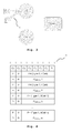
- Fig. 1 schematically depicts a cellular service communication scenario. Even if two User Equipments UE1, UE2 are in close proximity and communicate with each other, their data path 1 in the user plane goes via the operator network eNB, SGW/PGW.
- the typical data path 1 for this type of communication as shown in Fig. 1 involves the eNodeBs eNB and the Serving Gateways/Packet data network Gateways SGW/PGW.
- Fig. 2 schematically depicts a first proximity service communication scenario. If two or more User Equipments UE1, UE2 are in proximity to each other, they communicate by proximity service communication in direct mode with each other. For example, in LTE, the operator is able to move the data path 2 in the user plane off the access and core networks eNB, SGW/PGW onto direct links between the User Equipments UE1, UE2. The User Equipments communicate by a direct connection with each other. With regard to the data path 2, the eNodeBs eNB and the Serving Gateways/Packet data network Gateways SGW/PGW are not involved in a direct mode proximity service communication.
- Fig. 3 schematically depicts a second proximity service communication scenario. If two or more User Equipments UE1, UE2 are in proximity to each other, they communicate locally-routed by proximity service communication with each other. Locally-routed means that the data path 3 in the user plane is routed via an eNodeB eNB, which is shared by both User Equipments UE1, UE2.
- the data path 3 does not include the core network, e.g. the Serving Gateways/Packet data network Gateways SGW/PGW are not involved in a locally routed proximity service communication.
- Another mode of a proximity service communication scenario is that two User Equipments UE1, UE2 perform direct communication between each other. However the transmission grant for communication between the two User Equipments UE1, UE2 is allocated by the eNodeB eNB. This is a variation of locally routed proximity service communication, even though the data path for the proximity service communication is directly from one User Equipment UE1, UE2 to the other User Equipment UE2, UE1 and is not via the eNodeB eNB.
- a Power Headroom reporting procedure is defined in 3GPP TS 36.321 - 5.4.6.
- the Power Headroom reporting procedure is used to provide the scheduling eNodeB eNB with information about the difference between the nominal User Equipment maximum transmit power and the estimated power for UL-SCH transmission per activated Serving Cell and also with information about the difference between the nominal User Equipment maximum power and the estimated power for UL-SCH and PUCCH transmission on PCell.
- RRC controls Power Headroom reporting by configuring two timers periodicPHR-Timer and prohibitPHR-Timer, and by signaling dl-PathlossChange which sets the change in measured downlink pathloss and the required power backoff due to power management to trigger a Power Headroom Report.
- a Power Headroom Report is triggered if any of the following events occur:
- the User Equipment UE1, UE2 avoids triggering a Power Headroom Report when the required power backoff due to power management decreases only temporarily (e.g. for up to a few tens of milliseconds) and it should avoid reflecting such temporary decrease in the values of P CMAX,c /PH when a Power Headroom Report is triggered by other triggering conditions.
- the estimated power of UL-SCH transmission depends on the transport block format, downlink pathloss estimation, allocated resources for the UL-SCH transmission, etc.
- P CMAX,c is defined as a value range where P CMAX,c is set at the User Equipment to be a value within the specified range.
- the value range depends on User Equipment power class, the maximum transmit power signalled by the network, P EMAX , maximum power reduction, MPR, additional maximum power reduction, A-MPR, and the transmission bandwidth.
- P CMAX,c and the value range are defined in 3GPP TS 36.101 as follows:
- the User Equipment sets its P CMAX,c .
- the configured maximum output power P CMAX,c on serving cell c is set within the following bounds: P CMAX_L , c ⁇ P CMAX , c ⁇ P CMAX_H , c
- P CMAX_L , c MIN P EMAX , c - ⁇ T C , c , P PowerClass - MAX MPR c + A - MPR c , P - MPR c , P - pro_se - ⁇ T C , c
- P CMAX_L , c MIN P EMAX , c - ⁇ T C , c , P PowerClass - MAX MPR c + A - MPR c , P - MPR c , P - pro_se - ⁇ T C , c .
- P CMAX_H , c MIN P EMAX , c P PowerClass
- P EMAX,c is the value given by IE P-Max for serving cell c.
- P PowerClass is the maximum User Equipment power specified in Table 6.2.2-1 of 3GPP TS 36.101 without taking into account the tolerance specified in the Table 6.2.2-1 of 3GPP TS 36.101.
- ⁇ T IB,c is the additional tolerance for serving cell c as specified in Table 6.2.5A-3 of 3GPP TS 36.101.
- MPR c and A-MPR c apply per serving cell c.
- P-MPR c accounts for power management for serving cell c.
- P-MPR power management for serving cell c.
- P-MPR c P-MPR.
- ⁇ T C,c 1.5 dB when Note 2 in Table 6.2.2-1 of 3GPP TS 36.101 applies to the serving cell c.
- ⁇ T C,c 0 dB when Note 2 in Table 6.2.2-1 of 3GPP TS 36.101 does not apply to the serving cell c.
- P CMAX_L P CMAX_L , c
- P CMAX_H P CMAX_H , c .
- the measured maximum output power P UMAX shall be within the following bounds: P CMAX_L - T P CMAX_L ⁇ P UMAX ⁇ P CMAX_H + T P CMAX_H
- the configured maximum output power P CMAX,c on serving cell depends on the frequency band combination used, A-MPR, MPR (addresses the regional band values which are specified in the standard) and P-MPR (accounts for power management when power backoff is applied).
- Fig. 4 depicts an Extended Power Headroom MAC control element 4 according to 3GPP TS 36.321 for transmitting a Power Headroom Report.
- the Extended Power Headroom MAC Control Element 4 is defined as follows:
- Fig. 5 depicts an Extended Power Headroom MAC control element 5 according to one embodiment of the invention.
- sufficient information on the available User Equipment UE1, UE2 transmission power is provided to the network, e.g. the Scheduler which is included in the eNodeB eNB or is a separate Scheduler for multiple eNodeBs eNB. This is realized by signaling the nominal User Equipment maximum transmission power and/or the power reduction imposed due to the proximity service communication together with the Power Headroom Report.
- the Power Headroom report is provided to the Scheduler by the Extended Power Headroom MAC control element 5.
- the calculation of the Power Headroom report takes into account the power used in proximity service communication.
- the value range for the nominal User Equipment maximum transmission power which is communicated takes into account the possible power variation caused by proximity service communication. Therefore, the calculation of nominal User Equipment maximum transmission power and the power headroom reporting also reflects the power reduction due to proximity service communication.
- the Power Headroom Report information to indicate whether the User Equipment applies power sharing between cellular service communication and proximity service communication is included.
- the User Equipment informs the network, i.e. the Scheduler if the calculated Power Headroom Report would have different values if the User Equipment did not perform proximity service communication and cellular service communication simultaneously at the time of the Power Headroom Report calculation.
- the "P" bit is used to indicate whether the power management due to power backoff is applied for Power Headroom Report calculation for the concerning service cell.
- the "R" (reserved) bits in Extended Power Headroom MAC control element is used for indicating if power reduction due to proximity service communication was considered when calculating the corresponding Power Headroom Report. These bits are indicated as "PR" in Fig. 5 . If the "PR" bit is set to 1, the power reduction due to proximity service communication is applied for the corresponding Power Headroom.
- the network i.e. the Scheduler is informed of the power reduction caused by proximity service communication.
- the value range for P CMAX,C is defined taking into account the possible proximity service communication.
- P CMAX,C is: P CMAX_L ⁇ P CMAX , c ⁇ P CMAX_H
- P-pro_se defines the maximum power reduction due to proximity service communication in the corresponding band.
- the value for P-pro_se is defined for different band combinations of proximity service communication, operating frequency bands and resource allocation. The embodiment is described for intra-band contiguous carrier aggregation. In one embodiment, similar definition is proposed for other band combinations as well as non-carrier aggregation scenarios.
- P-pro_se is defined as the total maximum power reduction due to the proximity service communication independent of the operating band of proximity service communication.
- the transmission power reduction is included within P-MPR C
- the value range defined for P-MPR c is adapted to reflect the possible power reduction due to the proximity service communication.
- the network is not aware if the power reduction is caused by the power backoff resulting from legacy dual transmission on multiple radio networks or by to the proximity service communication.
- a frequent Power Headroom Report and P CMAX,C transmission due to the reduction of power due to proximity service communication is controlled by a prohibitPHRPpro_se-Timer.
- a Power Headroom Report is triggered in addition to the triggering as described in 3GPP TS 36.321 if the following events occur:
- the corresponding Power Headroom Report for the uplink transmission and the corresponding P CMAX,C are signaled to the network in the next available uplink transmission.
- the prohibitPHRPpro_se-Timer is restarted after transmission of Power Headroom Report and P CMAX,C .
- a frequent Power Headroom Report and P CMAX,C transmission due to the reduction of power due to proximity service communication is controlled by a timer prohibitPHRP-Timer.
- a Power Headroom Report is triggered in addition to the triggering as described above, if the following events occur:
- prohibitPHR-Timer and dl-PathlossChange are used in known systems and are further used according to this embodiment to reflect power reduction due to proximity service communication.
- the corresponding Power Headroom Report for the uplink transmission and the corresponding P CMAX,C are signalled to the network in the next available uplink transmission.
- prohibitPHR-Timer is restarted after the transmission of the Power Headroom Report and the P CMAX, C .
- DSP digital signal processor
- ASIC application specific integrated circuit
- FPGA field programmable gate array
- ROM read only memory
- RAM random access memory
Landscapes
- Engineering & Computer Science (AREA)
- Computer Networks & Wireless Communication (AREA)
- Signal Processing (AREA)
- Quality & Reliability (AREA)
- Mobile Radio Communication Systems (AREA)
Abstract
Description
- The present invention relates to a method, User Equipment and Scheduler for Power Headroom reporting for cellular service communication and proximity service communications.
- This section introduces aspects that may be helpful in facilitating a better understanding of the invention. Accordingly, the statements of this section are to be read in this light and are not to be understood as admission about what is in the prior art.
- 3GPP launched a feasibility study for proximity services which is published in 3GPP TR22.803. According to the public safety support defined by 3GPP, a User Equipment is required to communicate to multiple public safety user groups via proximity service communication and to access cellular communication services at the same time. Multi-carrier operation is supported for proximity service communication and cellular service communication. Thus, the User Equipment either operates on different frequencies for cellular service communication and proximity service communication or shares the same frequency for proximity service communication and cellular service communication.
- According to 3GPP TR 22.803, cellular service communication is understood as communication between the User Equipment and the eNodeB and the network. Proximity service communication is understood as communication between two proximity service enabled User Equipments without sending user data through the network and without including an eNodeB (direct mode). Further, proximity service communication may take place between two proximity service enabled User Equipments locally routed via one eNodeB but without using the network (locally routed mode).
- Therefore, cellular service communication and proximity service communication have different destination points even though they originate from the same User Equipment. This results in power control issues especially if the User Equipment performs simultaneous transmission for cellular service communication and proximity service communication.
- If only cellular service communication takes place, a Scheduler receives information about the User Equipment's power situation via the User Equipment's Power Headroom Report (3GPP TS 36.321). Based on this information, the Scheduler schedules an appropriate data size and Modulation and Coding Scheme for the uplink transmission by the User Equipment. The Power Headroom Report is calculated by the User Equipment based on the path loss, the transmission power and other parameters at the time of Power Headroom Report transmission.
- A problem arises if the Power Headroom Report is calculated when simultaneous cellular service communication and proximity service communication is performed by the User Equipment. The Scheduler of the network may schedule the User Equipment for higher transmission power for cellular service communication and the User Equipment may fail to deliver such transmission power. This negatively impacts the system performance. In addition, there is a possibility for miss-match between the network and the User Equipment on the power control of the sounding reference signal transmission which leads to inaccuracy in channel estimation at the network and penetrates overall system performance.
- It is an object of the invention to provide a new concept for addressing the above mentioned problems in networks which allow simultaneous cellular service communication and proximity service communication.
- According to one embodiment, a method for power management in a cellular network is disclosed. At least some User Equipments in the cellular network are capable of cellular service communication and proximity service communication. A User Equipment sends a Power Headroom Report to a Scheduler. The Scheduler is integrated in an eNodeB or is located somewhere in the network for serving multiple eNodesBs. The Power Headroom Report at least contains a power reduction measure reflecting a power reduction if the User Equipment performs proximity service communication. Thus, with this power reduction measure the Scheduler is informed about the User Equipment's simultaneous cellular service communication and proximity service communication and about power sharing information corresponding to these simultaneous communications. Proximity service communication and cellular service communication are understood as defined in the background section above. This has the advantage that the knowledge of the Scheduler about power sharing between cellular service communication and proximity service communication in the User Equipment when generating the Power Headroom Report improves the accuracy in channel estimation in the network and improves the overall system performance.
- According to one embodiment, the Power Headroom Report contains an index indicating if the User Equipment applies power sharing between cellular service communication and proximity service communication. Thus, from this index the Scheduler determines if the power given in the Power Headroom Report is affected by proximity service communication or not.
- According to one embodiment, the lower limit for the configured maximum User Equipment power for serving a cell c PCMAX,C is defined as PCMAX_L,c = MIN {PEMAX,c - ΔTC,c, PPowerClass -
- MAX (MPRc + A-MPRc, P-MPRc, P-pro_se) - ΔTC,c}. P_pro-se is a parameter for the power reduction in case proximity service communication takes place in the User Equipment.
- According to one embodiment, the power reduction in case of proximity service communication P-pro_se is defined in a lookup table for different combinations of at least one of band combinations of proximity service transmissions, operating frequency bands and resource allocation.
- According to one embodiment, the power reduction in case of proximity service communication P-pro_se is defined as a single value for maximum power reduction independent of the operating band.
- According to one embodiment, the lower limit for the configured maximum User Equipment power is defined as

- According to one embodiment, the power reduction in case of proximity service communication is included in the Power Management Maximum Power Reduction parameter for serving a cell P-MPRc. Thus, there is no special value for power reduction communicated with the Power Headroom Report. In one embodiment, an index gives the information if the Power Management Maximum Power Reduction parameter was altered to reflect the power reduction caused by proximity service communication.
- According to one embodiment, a reserved bit in the Power Headroom Report is used to indicate if power reduction due to proximity service communication is applied to the corresponding Power Headroom Report.
- According to one embodiment, sending a Power Headroom Report by the User Equipment is triggered if a timer expires or has expired and the power reduction due to proximity service communication for this cell has changed more than a specified threshold value.
- According to one embodiment, a method for power management in a cellular network is proposed. At least some User Equipments in the cellular network are capable of cellular service communication and proximity service communication. The method comprises a receiving step for receiving a Power Headroom Report by a Scheduler from at least one User Equipment. The Scheduler is integrated in an eNodeB or is located somewhere in the network for serving multiple eNodesBs. The Power Headroom Report at least contains a power reduction measure reflecting a power reduction if the User Equipment performs proximity service communication. Thus, with this power reduction measure received by the Scheduler, the Scheduler is informed about the User Equipments simultaneous cellular service communication and proximity service communication and about power sharing information corresponding to these simultaneous communications at the time of generating the Power Headroom Report. Proximity service communication and cellular service communication are understood as defined in the background section. This has the advantage that the knowledge of the Scheduler about power sharing between cellular service communication and proximity service communication in the User Equipment when generating the Power Headroom Report improves the accuracy in channel estimation in the network and improves the overall system performance.
- According to one embodiment, the Power Headroom Report contains an index indicating if the User Equipment applies power sharing between cellular service communication and proximity service communication.
- According to one embodiment, the lower limit for the configured maximum User Equipment power for serving a cell PCMAX,C is defined as

- According to one embodiment, a Scheduler in a cellular network is proposed. The Scheduler comprises a receiver for receiving at least one Power Headroom Report. The Scheduler further comprises a scheduling entity for scheduling radio resources for at least one User Equipment. The Power Headroom Report at least contains a power reduction measure reflecting a power reduction if the at least one User Equipment performs proximity service communication. The scheduling entity uses the information received about power reduction for scheduling the radio resources.
- According to one embodiment, a User Equipment in a cellular network performing the above mentioned method is proposed.
- According to one embodiment, a Base Station in a cellular network performing the above mentioned method is proposed.
- According to one embodiment, a Base Station in a cellular network which comprises a Scheduler as described above is proposed.
- Further advantageous features of the embodiments of the invention are defined and are described in the following detailed description.
- Some embodiments of apparatus and methods in accordance with embodiments of the present invention are now described, by way of examples only, and with reference to the accompanying drawings, in which:
- Fig. 1
- schematically depicts a cellular service communication scenario
- Fig. 2
- schematically depicts a first proximity service communication scenario
- Fig. 3
- schematically depicts a second proximity service communication scenario
- Fig. 4
- depicts a Power Headroom MAC control element as known in the art
- Fig. 5
- depicts an Extended Power Headroom MAC control element according to the invention
- The description and drawings merely illustrate the principles of the invention. It will thus be appreciated that those skilled in the art will be able to devise various arrangements that, although not explicitly described or shown herein, embody the principles of the invention and are included within its spirit and scope. Furthermore, all examples recited herein are principally intended expressly to be only for pedagogical purposes to aid the reader in understanding the principles of the invention and the concepts contributed by the inventors to furthering the art, and are to be construed as being without limitation to such specifically recited examples and conditions. Moreover, all statements herein reciting principles, aspects, and embodiments of the invention, as well as specific examples thereof, are intended to encompass equivalents thereof.
-
Fig. 1 schematically depicts a cellular service communication scenario. Even if two User Equipments UE1, UE2 are in close proximity and communicate with each other, theirdata path 1 in the user plane goes via the operator network eNB, SGW/PGW. Thetypical data path 1 for this type of communication as shown inFig. 1 involves the eNodeBs eNB and the Serving Gateways/Packet data network Gateways SGW/PGW. -
Fig. 2 schematically depicts a first proximity service communication scenario. If two or more User Equipments UE1, UE2 are in proximity to each other, they communicate by proximity service communication in direct mode with each other. For example, in LTE, the operator is able to move thedata path 2 in the user plane off the access and core networks eNB, SGW/PGW onto direct links between the User Equipments UE1, UE2. The User Equipments communicate by a direct connection with each other. With regard to thedata path 2, the eNodeBs eNB and the Serving Gateways/Packet data network Gateways SGW/PGW are not involved in a direct mode proximity service communication. -
Fig. 3 schematically depicts a second proximity service communication scenario. If two or more User Equipments UE1, UE2 are in proximity to each other, they communicate locally-routed by proximity service communication with each other. Locally-routed means that thedata path 3 in the user plane is routed via an eNodeB eNB, which is shared by both User Equipments UE1, UE2. Thedata path 3 does not include the core network, e.g. the Serving Gateways/Packet data network Gateways SGW/PGW are not involved in a locally routed proximity service communication. - Another mode of a proximity service communication scenario is that two User Equipments UE1, UE2 perform direct communication between each other. However the transmission grant for communication between the two User Equipments UE1, UE2 is allocated by the eNodeB eNB. This is a variation of locally routed proximity service communication, even though the data path for the proximity service communication is directly from one User Equipment UE1, UE2 to the other User Equipment UE2, UE1 and is not via the eNodeB eNB.
- For proximity communication as depicted in
Fig. 2 and3 , a Power Headroom reporting procedure is defined in 3GPP TS 36.321 - 5.4.6. - The Power Headroom reporting procedure is used to provide the scheduling eNodeB eNB with information about the difference between the nominal User Equipment maximum transmit power and the estimated power for UL-SCH transmission per activated Serving Cell and also with information about the difference between the nominal User Equipment maximum power and the estimated power for UL-SCH and PUCCH transmission on PCell.
- RRC controls Power Headroom reporting by configuring two timers periodicPHR-Timer and prohibitPHR-Timer, and by signaling dl-PathlossChange which sets the change in measured downlink pathloss and the required power backoff due to power management to trigger a Power Headroom Report.
- A Power Headroom Report is triggered if any of the following events occur:
- prohibitPHR-Timer expires or has expired and the path loss has changed more than dl-PathlossChange dB for at least one activated Serving Cell which is used as a pathloss reference since the last transmission of a Power Headroom Report when the User Equipment has uplink resources for new transmission;
- periodicPHR-Timer expires;
- upon configuration or reconfiguration of the Power Headroom reporting functionality by upper layers, which is not used to disable the function;
- activation of an SCell with configured uplink;
- prohibitPHR-Timer expires or has expired, when the User Equipment has uplink resources for new transmission, and the following is true in this TTI for any of the actived Serving Cells with configured uplink:
- there are uplink resources allocated for transmission or there is a PUCCH transmission on this cell, and the required power backoff due to power management (as allowed by P-MPRc) for this cell has changed more than dl-PathlossChange dB since the last transmission of a Power Headroom Report when the User Equipment had uplink resources allocated for transmission or PUCCH transmission on this cell.
- The User Equipment UE1, UE2 avoids triggering a Power Headroom Report when the required power backoff due to power management decreases only temporarily (e.g. for up to a few tens of milliseconds) and it should avoid reflecting such temporary decrease in the values of PCMAX,c/PH when a Power Headroom Report is triggered by other triggering conditions.
- The estimated power of UL-SCH transmission depends on the transport block format, downlink pathloss estimation, allocated resources for the UL-SCH transmission, etc. PCMAX,c is defined as a value range where PCMAX,c is set at the User Equipment to be a value within the specified range. The value range depends on User Equipment power class, the maximum transmit power signalled by the network, PEMAX, maximum power reduction, MPR, additional maximum power reduction, A-MPR, and the transmission bandwidth.
- PCMAX,c and the value range are defined in 3GPP TS 36.101 as follows:
- The User Equipment sets its PCMAX,c. The configured maximum output power PCMAX,c on serving cell c is set within the following bounds:

- For intra-band contiguous carrier aggregation:

- For inter-band non-contiguous carrier aggregation:


- PEMAX,c is the value given by IE P-Max for serving cell c.
- PPowerClass is the maximum User Equipment power specified in Table 6.2.2-1 of 3GPP TS 36.101 without taking into account the tolerance specified in the Table 6.2.2-1 of 3GPP TS 36.101.
- ΔTIB,c is the additional tolerance for serving cell c as specified in Table 6.2.5A-3 of 3GPP TS 36.101.
- For inter-band carrier aggregation, MPRc and A-MPRc apply per serving cell c. For intra-band contiguous carrier aggregation, MPRc = MPR and A-MPRc = A-MPR.
- P-MPRc accounts for power management for serving cell c. For intra-band carrier aggregation, there is one power management term P-MPR for the User Equipment and P-MPRc = P-MPR.
- ΔTC,c equals 1.5 dB when
Note 2 in Table 6.2.2-1 of 3GPP TS 36.101 applies to the serving cell c. - ΔTC,c equals 0 dB when
Note 2 in Table 6.2.2-1 of 3GPP TS 36.101 does not apply to the serving cell c. - For inter-band carrier aggregation with one uplink serving cell the total configured maximum output power PCMAX shall be set within the following bounds:

wherein
and
- The measured maximum output power PUMAX shall be within the following bounds:

- In summary, the configured maximum output power PCMAX,c on serving cell depends on the frequency band combination used, A-MPR, MPR (addresses the regional band values which are specified in the standard) and P-MPR (accounts for power management when power backoff is applied).
-
Fig. 4 depicts an Extended Power HeadroomMAC control element 4 according to 3GPP TS 36.321 for transmitting a Power Headroom Report. The Extended Power HeadroomMAC Control Element 4 is defined as follows: - Ci: this field indicates the presence of a Power Headroom field for the SCell with SCellIndex i. The Ci field set to "1" indicates that a Power Headroom field for the SCell with SCellIndex i is reported. The Ci field set to "0" indicates that a Power Headroom field for the SCell with SCellIndex i is not reported.
- R: reserved bit, set to "0";
- V: this field indicates if the Power Headroom value is based on a real transmission or a reference format. For
Type 1 Power Headroom, V=0 indicates real transmission on PUSCH and V=1 indicates that a PUSCH reference format is used. ForType 2 Power Headroom, V=0 indicates real transmission on PUCCH and V=1 indicates that a PUCCH reference format is used. Furthermore, for bothType 1 andType 2 Power Headroom, V=0 indicates the presence of the associated PCMAX,c field, and V=1 indicates that the associated PCMAX,c field is omitted; - Power Headroom PH: this field indicates the power headroom level. The length of the field is 6 bits. Further,
Type 1 orType 2 Power Headroom and PCell/SCell are indicated. - P: this field indicates whether the User Equipment applies power backoff due to power management (as allowed by P-MPRc) . The User Equipment shall set P=1 if the corresponding PCMAX,c field would have had a different value if no power backoff due to power management had been applied.
- PCMAX,c: if present, this field indicates the PCMAX,c or P̃CMAX,c used for calculation of the preceding Power Headroom field.
-
Fig. 5 depicts an Extended Power HeadroomMAC control element 5 according to one embodiment of the invention. - According to the invention, sufficient information on the available User Equipment UE1, UE2 transmission power is provided to the network, e.g. the Scheduler which is included in the eNodeB eNB or is a separate Scheduler for multiple eNodeBs eNB. This is realized by signaling the nominal User Equipment maximum transmission power and/or the power reduction imposed due to the proximity service communication together with the Power Headroom Report. The Power Headroom report is provided to the Scheduler by the Extended Power Headroom
MAC control element 5. - Therefore, the calculation of the Power Headroom report takes into account the power used in proximity service communication. The value range for the nominal User Equipment maximum transmission power which is communicated takes into account the possible power variation caused by proximity service communication. Therefore, the calculation of nominal User Equipment maximum transmission power and the power headroom reporting also reflects the power reduction due to proximity service communication.
- In the Power Headroom Report, information to indicate whether the User Equipment applies power sharing between cellular service communication and proximity service communication is included. In other words, the User Equipment informs the network, i.e. the Scheduler if the calculated Power Headroom Report would have different values if the User Equipment did not perform proximity service communication and cellular service communication simultaneously at the time of the Power Headroom Report calculation.
- In the Extended Power Headroom MAC control element according to
Fig. 5 , the "P" bit is used to indicate whether the power management due to power backoff is applied for Power Headroom Report calculation for the concerning service cell. In addition, the "R" (reserved) bits in Extended Power Headroom MAC control element is used for indicating if power reduction due to proximity service communication was considered when calculating the corresponding Power Headroom Report. These bits are indicated as "PR" inFig. 5 . If the "PR" bit is set to 1, the power reduction due to proximity service communication is applied for the corresponding Power Headroom. By the Extended Power HeadroomMAC control element 5, the network, i.e. the Scheduler is informed of the power reduction caused by proximity service communication. - According to one embodiment, the value range for PCMAX,C is defined taking into account the possible proximity service communication.
- Exemplarily, the value range for PCMAX,C is:

Wherein - For intra-band contiguous carrier aggregation, the lower bound for PCMAX,C is set as follows:

and the higher bound for PCMAX,C is set as follows:
- P-pro_se defines the maximum power reduction due to proximity service communication in the corresponding band. In one embodiment, the value for P-pro_se is defined for different band combinations of proximity service communication, operating frequency bands and resource allocation. The embodiment is described for intra-band contiguous carrier aggregation. In one embodiment, similar definition is proposed for other band combinations as well as non-carrier aggregation scenarios.
- In one embodiment, P-pro_se is defined as the total maximum power reduction due to the proximity service communication independent of the operating band of proximity service communication.
- According to one embodiment, the lower bound for PCMAX,C is set as follows:

- According to one embodiment, the transmission power reduction is included within P-MPRC In this case, it is not necessary to define a separate parameter for the transmission power reduction due to proximity service communication. Rather the value range defined for P-MPRc is adapted to reflect the possible power reduction due to the proximity service communication. However, in such scenario, the network is not aware if the power reduction is caused by the power backoff resulting from legacy dual transmission on multiple radio networks or by to the proximity service communication.
- According to one embodiment, a frequent Power Headroom Report and PCMAX,C transmission due to the reduction of power due to proximity service communication is controlled by a prohibitPHRPpro_se-Timer. A Power Headroom Report is triggered in addition to the triggering as described in 3GPP TS 36.321 if the following events occur:
- prohibitPHRPpro_se-Timer expires or has expired and the power reduction due to proximity service communication for this cell has changed more than a specified threshold value, ConfigPpro_seChange, since the last transmission of a Power Headroom Report.
- The corresponding Power Headroom Report for the uplink transmission and the corresponding PCMAX,C are signaled to the network in the next available uplink transmission. The prohibitPHRPpro_se-Timer is restarted after transmission of Power Headroom Report and PCMAX,C.
- According to one embodiment, a frequent Power Headroom Report and PCMAX,C transmission due to the reduction of power due to proximity service communication is controlled by a timer prohibitPHRP-Timer. A Power Headroom Report is triggered in addition to the triggering as described above, if the following events occur:
- prohibitPHR-Timer expires or has expired and the power reduction due to proximity service communication for this cell has changed more than a specified threshold value, dl-PathlossChange, since the last transmission of a Power Headroom Report.
- prohibitPHR-Timer and dl-PathlossChange are used in known systems and are further used according to this embodiment to reflect power reduction due to proximity service communication.
- The corresponding Power Headroom Report for the uplink transmission and the corresponding PCMAX,C are signalled to the network in the next available uplink transmission. prohibitPHR-Timer is restarted after the transmission of the Power Headroom Report and the PCMAX, C.
- The functions of the various elements shown in the Figures, including any functional blocks, may be provided through the use of dedicated hardware as well as hardware capable of executing software in association with appropriate software. When provided by a processor, the functions may be provided by a single dedicated processor, by a single shared processor, or by a plurality of individual processors, some of which may be shared. Moreover, the functions may be provided, without limitation, by digital signal processor (DSP) hardware, network processor, application specific integrated circuit (ASIC), field programmable gate array (FPGA), read only memory (ROM) for storing software, random access memory (RAM), and non volatile storage. Other hardware, conventional and/or custom, may also be included.
Claims (15)
- A method for power management in a cellular network, comprising the steps:- sending a Power Headroom Report by a User Equipment (UE1, UE2), wherein the Power Headroom Report at least contains a power reduction measure reflecting a power reduction if the User Equipment (UE1, UE2) performs proximity service communication.
- A method for power management according to claim 1, wherein the Power Headroom Report contains an index (PR) indicating if the User Equipment (UE1, UE2) applies power sharing between cellular services and proximity services.
- A method for power management according to one of claims 1 or 2, wherein the lower limit for the configured maximum User Equipment power for serving a cell PCMAX,C is defined as

- A method for power management according to one of claims 1 or 3, wherein the power reduction in case of proximity service communication P-pro_se is defined in a lookup table for different combinations of at least one of band combinations of proximity service transmissions, operating frequency bands and resource allocation.
- A method for power management according to one of claims 1 or 3, wherein the power reduction in case of proximity service communication P-pro_se is defined as a single value for maximum power reduction independent of the operating band.
- A method for power management according to one of claims 1 or 2, wherein the lower limit for the configured maximum User Equipment power is defined as

- A method for power management according to claim 1, wherein the power reduction in case of proximity service communication is included in the Power Management Maximum Power Reduction parameter for serving a cell P-MPRc.
- A method for power management according to one of claims 1 or 7, wherein a reserved bit (PR) in the Power Headroom Report is used to indicate if power reduction due to proximity service transmission is applied to the corresponding Power Headroom Report.
- A method for power management according to one of claims 1 or 8, wherein sending a Power Headroom Report is triggered if a timer expires or has expired and the power reduction due to proximity service communication for this cell has changed more than a specified threshold value.
- A method for power management in a cellular network, comprising the steps:- receiving a Power Headroom Report by a Scheduler (eNB) from at least one User Equipment (UE1, UE2), wherein the Power Headroom Report at least containsa power reduction measure reflecting a power reduction if the User Equipment (UE1, UE2) performs proximity service communication.
- A method for power management according to claim 10, wherein the Power Headroom Report contains an index indicating if the User Equipment (UE1, UE2) applies power sharing between cellular services and proximity services.
- A method for power management according to one of claims 10 and 11, wherein the lower limit for the configured maximum User Equipment power for serving a cell PCMAX,C is defined as

- A Scheduler in a cellular network, comprising:- a receiver for receiving at least one Power Headroom Report,- a scheduling entity for scheduling radio resources for at least one User Equipment (UE1, UE2), wherein the Power Headroom Report at least contains a power reduction measure reflecting a power reduction if the at least one User Equipment (UE1, UE2) performs proximity service communication and the scheduling entity uses the information received about power reduction for scheduling the radio resources.
- A User Equipment in a cellular network, wherein the User Equipment performs a method according to one of claims 1 to 9.
- A Base Station in a cellular network, wherein the Base Station performs a method according to one of claims 9 to 13.
Priority Applications (7)
| Application Number | Priority Date | Filing Date | Title |
|---|---|---|---|
| EP14306787.4A EP3018951A1 (en) | 2014-11-07 | 2014-11-07 | Method and apparatus to handle multi-carrier operation in case of cellular service communication and proximity service communication |
| KR1020177015465A KR20170081241A (en) | 2014-11-07 | 2015-10-26 | Method and apparatus to handle multi-carrier operation in case of cellular service communication and proximity service communication |
| JP2017542288A JP2017538370A (en) | 2014-11-07 | 2015-10-26 | Method and apparatus for handling multi-carrier operations in the case of cellular service communication and proximity service communication |
| PCT/EP2015/074739 WO2016071139A1 (en) | 2014-11-07 | 2015-10-26 | Method and apparatus to handle multi-carrier operation in case of cellular service communication and proximity service communication |
| US15/524,766 US20170318547A1 (en) | 2014-11-07 | 2015-10-26 | Method and apparatus to handle multi-carrier operation in case of cellular service communication and proximity service communication |
| CN201580059850.1A CN107113746A (en) | 2014-11-07 | 2015-10-26 | Method and apparatus for handling multi-carrier operation in case of cellular service communication and proximity service communication |
| TW104135245A TWI592044B (en) | 2014-11-07 | 2015-10-27 | Method and apparatus to handle multi-carrier operation in case of cellular service communication and proximity service communication |
Applications Claiming Priority (1)
| Application Number | Priority Date | Filing Date | Title |
|---|---|---|---|
| EP14306787.4A EP3018951A1 (en) | 2014-11-07 | 2014-11-07 | Method and apparatus to handle multi-carrier operation in case of cellular service communication and proximity service communication |
Publications (1)
| Publication Number | Publication Date |
|---|---|
| EP3018951A1 true EP3018951A1 (en) | 2016-05-11 |
Family
ID=51999377
Family Applications (1)
| Application Number | Title | Priority Date | Filing Date |
|---|---|---|---|
| EP14306787.4A Withdrawn EP3018951A1 (en) | 2014-11-07 | 2014-11-07 | Method and apparatus to handle multi-carrier operation in case of cellular service communication and proximity service communication |
Country Status (7)
| Country | Link |
|---|---|
| US (1) | US20170318547A1 (en) |
| EP (1) | EP3018951A1 (en) |
| JP (1) | JP2017538370A (en) |
| KR (1) | KR20170081241A (en) |
| CN (1) | CN107113746A (en) |
| TW (1) | TWI592044B (en) |
| WO (1) | WO2016071139A1 (en) |
Families Citing this family (2)
| Publication number | Priority date | Publication date | Assignee | Title |
|---|---|---|---|---|
| US10165526B2 (en) * | 2015-01-13 | 2018-12-25 | Lg Electronics Inc. | Method for de-configuring a SCell from PUCCH resource in a carrier aggregation system and a device therefor |
| CN110536400B (en) * | 2018-05-25 | 2021-06-22 | 华为技术有限公司 | A method and apparatus for sending a power headroom report |
Citations (2)
| Publication number | Priority date | Publication date | Assignee | Title |
|---|---|---|---|---|
| US20130324182A1 (en) * | 2012-05-31 | 2013-12-05 | Interdigital Patent Holdings, Inc. | Device-to-device (d2d) cross link power control |
| WO2014110747A1 (en) * | 2013-01-17 | 2014-07-24 | 富士通株式会社 | Power headroom reporting method and device |
Family Cites Families (2)
| Publication number | Priority date | Publication date | Assignee | Title |
|---|---|---|---|---|
| EP3214875B1 (en) * | 2011-01-07 | 2020-10-07 | InterDigital Patent Holdings, Inc. | Methods, apparatus and systems for handling additional power backoff |
| CN103781111A (en) * | 2012-10-23 | 2014-05-07 | 普天信息技术研究院有限公司 | Method for reporting power headroom |
-
2014
- 2014-11-07 EP EP14306787.4A patent/EP3018951A1/en not_active Withdrawn
-
2015
- 2015-10-26 US US15/524,766 patent/US20170318547A1/en not_active Abandoned
- 2015-10-26 WO PCT/EP2015/074739 patent/WO2016071139A1/en not_active Ceased
- 2015-10-26 KR KR1020177015465A patent/KR20170081241A/en not_active Ceased
- 2015-10-26 CN CN201580059850.1A patent/CN107113746A/en active Pending
- 2015-10-26 JP JP2017542288A patent/JP2017538370A/en active Pending
- 2015-10-27 TW TW104135245A patent/TWI592044B/en not_active IP Right Cessation
Patent Citations (2)
| Publication number | Priority date | Publication date | Assignee | Title |
|---|---|---|---|---|
| US20130324182A1 (en) * | 2012-05-31 | 2013-12-05 | Interdigital Patent Holdings, Inc. | Device-to-device (d2d) cross link power control |
| WO2014110747A1 (en) * | 2013-01-17 | 2014-07-24 | 富士通株式会社 | Power headroom reporting method and device |
Also Published As
| Publication number | Publication date |
|---|---|
| US20170318547A1 (en) | 2017-11-02 |
| TWI592044B (en) | 2017-07-11 |
| TW201632005A (en) | 2016-09-01 |
| KR20170081241A (en) | 2017-07-11 |
| WO2016071139A1 (en) | 2016-05-12 |
| CN107113746A (en) | 2017-08-29 |
| JP2017538370A (en) | 2017-12-21 |
Similar Documents
| Publication | Publication Date | Title |
|---|---|---|
| US11895599B2 (en) | Power-limit reporting in a communication system using carrier aggregation | |
| US20250142484A1 (en) | Scheduled Uplink Transmission For Channel State Information Reporting | |
| US20230070002A1 (en) | Method for triggering power headroom reporting in a dual connectivity system and a device therefor | |
| JP6444972B2 (en) | Method and apparatus for efficiently reporting terminal transmission power | |
| RU2645753C2 (en) | Power control and power headroom reporting for dual connectivity | |
| EP2583505B1 (en) | Carrier aggregation with power headroom report | |
| US9629097B2 (en) | Method and apparatus for configuring uplink transmission power based on time alignment groups | |
| US10028237B2 (en) | Triggering power headroom reporting in TDD system | |
| EP2566231B1 (en) | Mobile communication method and mobile station | |
| KR20140121099A (en) | Method and apparatus for transmitting power headroom report of user equipment in wireless communication system | |
| CN103391609A (en) | Method and apparatus for performing power headroom reporting procedure in wireless communication system | |
| KR20120048491A (en) | Method and apparatus for calculating power headroom in carrier aggregation mobile system | |
| JP2016525806A (en) | Power headroom reporting method and apparatus therefor in a wireless communication system that supports changing usage of radio resources | |
| EP3018951A1 (en) | Method and apparatus to handle multi-carrier operation in case of cellular service communication and proximity service communication | |
| KR20220158098A (en) | Power headroom reporting for additional SRS | |
| KR20130085884A (en) | Apparatus and method for transmitting power information of component carrier in multiple component carrier system |
Legal Events
| Date | Code | Title | Description |
|---|---|---|---|
| PUAI | Public reference made under article 153(3) epc to a published international application that has entered the european phase |
Free format text: ORIGINAL CODE: 0009012 |
|
| AK | Designated contracting states |
Kind code of ref document: A1 Designated state(s): AL AT BE BG CH CY CZ DE DK EE ES FI FR GB GR HR HU IE IS IT LI LT LU LV MC MK MT NL NO PL PT RO RS SE SI SK SM TR |
|
| AX | Request for extension of the european patent |
Extension state: BA ME |
|
| 17P | Request for examination filed |
Effective date: 20161111 |
|
| RBV | Designated contracting states (corrected) |
Designated state(s): AL AT BE BG CH CY CZ DE DK EE ES FI FR GB GR HR HU IE IS IT LI LT LU LV MC MK MT NL NO PL PT RO RS SE SI SK SM TR |
|
| STAA | Information on the status of an ep patent application or granted ep patent |
Free format text: STATUS: THE APPLICATION IS DEEMED TO BE WITHDRAWN |
|
| 18D | Application deemed to be withdrawn |
Effective date: 20161112 |