EP3018799A1 - Spring post for brush card for a power tool - Google Patents
Spring post for brush card for a power tool Download PDFInfo
- Publication number
- EP3018799A1 EP3018799A1 EP15193679.6A EP15193679A EP3018799A1 EP 3018799 A1 EP3018799 A1 EP 3018799A1 EP 15193679 A EP15193679 A EP 15193679A EP 3018799 A1 EP3018799 A1 EP 3018799A1
- Authority
- EP
- European Patent Office
- Prior art keywords
- brush
- spring
- card mount
- commutator
- leg
- Prior art date
- Legal status (The legal status is an assumption and is not a legal conclusion. Google has not performed a legal analysis and makes no representation as to the accuracy of the status listed.)
- Granted
Links
Images




Classifications
-
- H—ELECTRICITY
- H02—GENERATION; CONVERSION OR DISTRIBUTION OF ELECTRIC POWER
- H02K—DYNAMO-ELECTRIC MACHINES
- H02K5/00—Casings; Enclosures; Supports
- H02K5/04—Casings or enclosures characterised by the shape, form or construction thereof
- H02K5/14—Means for supporting or protecting brushes or brush holders
- H02K5/143—Means for supporting or protecting brushes or brush holders for cooperation with commutators
- H02K5/148—Slidably supported brushes
-
- H—ELECTRICITY
- H01—ELECTRIC ELEMENTS
- H01R—ELECTRICALLY-CONDUCTIVE CONNECTIONS; STRUCTURAL ASSOCIATIONS OF A PLURALITY OF MUTUALLY-INSULATED ELECTRICAL CONNECTING ELEMENTS; COUPLING DEVICES; CURRENT COLLECTORS
- H01R39/00—Rotary current collectors, distributors or interrupters
- H01R39/02—Details for dynamo electric machines
- H01R39/38—Brush holders
- H01R39/381—Brush holders characterised by the application of pressure to brush
Definitions
- the present disclosure relates to a brush assembly for electric motors, and more particularly to a brush assembly for motors used in electric power tools.
- Known portable power tools typically have an electric motor received within a tool housing.
- One common type of electric motor used in power tools has a rotor, a stator, and brushes.
- the rotor includes a rotor shaft, laminations mounted on the rotor shaft, armature windings wound in slots in the lamination stack, and a commutator mounted on the rotor shaft and electrically connected to the armature windings.
- the stator may have field windings wound in laminations, or may have permanent magnets.
- the brushes are mounted in brush housings, often known as brush boxes or brush holders, in sliding electrical contact with the commutator. Electric current is supplied from a power source through the brushes to the commutator, and from the commutator to the armature windings.
- the brushes and brush holders are typically part of a brush assembly(ies).
- the brush holders and brushes are disposed diametrically opposite to each other with the commutator disposed therebetween.
- the brush assembly(ies) includes springs that urge the brushes against the commutator.
- Exemplary brush assemblies may utilize two or four brushes around the commutator.
- Power tool are often used in harsh work environments and are susceptible to user drop and other impact. It is important to protect the internal components of the power tool, including the power tool motor, against damage in the event of drops.
- an electric motor including: a stator, an armature rotatably received within the stator, where the armature includes an armature shaft on which a commutator is mounted, and a brush assembly.
- the brush assembly includes a brush card mount disposed around the commutator; a brush holder mounted on a surface of the brush card mount; a brush disposed within the brush holder in sliding contact with the commutator to supply electric current to the commutator; a torsion spring secured to the brush card mount adjacent the brush holder, the spring having a leg arranged to engage a back surface of the brush; and a spring stop post disposed proximate an outer periphery of the brush card mount to limit an outward movement of the leg of the spring away from the back surface of the brush.
- the brush includes two curved surfaces with a groove formed therebetween.
- a distal end of the leg of the spring engages the groove of the brush.
- the distal end of the leg of the spring includes a hook engaging the groove of the brush.
- a spring post is provided projecting from the brush card mount, wherein the spring includes a wound portion secured around the spring post.
- the spring stop post is circumferentially located between the spring post and the brush holder within an angle formed between the brush holder and the spring post relative to a center of the brush card mount.
- the spring stop post is provided substantially adjacent the leg of the spring and the spring stop post is engageable with a middle portion or distal end of the leg of the spring.
- the brush holder includes an opening that is open-ended on a distal end of the brush holder and extends radially to accommodate the back and forth movement of the spring.
- the brush assembly comprises four brush holders housing four brushes.
- the brush assembly includes a housing portion substantially cylindrically shaped and extending from the brush card mount, the housing portion being arranged to mate with an end or around an outer surface of the motor stator.
- a power tool including a housing and the electric motor described above.
- a four-pole brush card for a power tool is described in detail in Patent Application No. 14/453,706, filed August 7, 2014 , which is incorporated by reference herein in its entirety.
- the present disclosure is directed to an improvement of the four-pole brush card according to an embodiment.
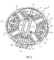
- Figs. 1 and 2 depict a brush assembly 100 (also referred to as brush card) according to an embodiment of the invention.
- the brush assembly 100 includes a brush card mount 102 and four brush holders 104.
- the brush card mount 102 has a substantially circular circumference and the four brush holders 104 are arranged equidistantly on four sides of the brush card mount 102.
- Each brush holder 104 accommodates a brush 106 therein.
- the brushes 106 housed in brush holders 104 facing each other are electrically connected to one another, as discussed below. Both ends of each brush holder 104 are open to allow radial movement of the brush 106 towards and away from a center of the brush card 100.
- the brush card mount 102 includes upright posts 108 in close proximity to the brush holders 104. Each post 108 is arranged to hold a wound portion of a spring 110. Each spring 110 includes an extended arm that engages a back surface of brush 106 inside the brush holder 104 to bias the brush 106 towards the center of the brush card 100.
- brush card mount 102 includes a planar portion 103, to which brush holders 104 are secured.
- a middle section of the planar portion 103 includes an opening that receives a motor commutator (not shown).
- the brush card mount 102 also includes a bridge portion 112 arranged above the commutator opening (and the commutator) and connected to the planar portion via four bridge legs 114a, 114b, 116a, and 116b.
- Bridge legs 114a, 114b, 116a, and 116b extend longitudinally (i.e., in the direction of the motor, at a substantially right angle with respect to the plane of the brush card mount 102) from the planar portion 103 to the bridge portion 112.
- Radially formed between bridge legs 114a, 114b, 116a, and 116b are gaps that allow for the radial movement of brushes 106.
- each brush holder 104 includes two radial openings on its outer (vertical) walls.
- One radial opening is disposed adjacent the spring post 108 to allow the spring 110 to radially bias the brush 106 toward the commutator.
- the other radial opening is to facilitate a wire connection to the brush.
- bridge leg 114a and 114b form walls that extend radially from the bridge portion 112 to (or near) outer edges of the brush card mount 102.
- the bridge legs 116a and 116b similarly extend towards (or near) outer edges of the brush card mount 102.
- This arrangement strengthens support for the bridge portion 112.
- bridge leg 114a mechanically supports and electrically isolates two terminals 118a and 118b provided on both sides of its outward-extending wall. Terminals 118a and 118b are connected to metal routings 120a and 120b, which extend over the bridge portion 112 to bridge leg 114b.
- Metal routings 120a and 120b connect the brushes 106 facing each other to one of the terminals 118a and 118b.
- metal routings 120a and 120b are connected via wires 122 to either corresponding brush holders 104 or brushes 106.
- metal routing 120a crosses over routing 120b to allow for opposite brushes 106/brush holders 104 to be connected to the same terminal 118a or 118b.
- the brush assembly also includes a housing portion 125 attached to the brush card mount 102.
- the housing portion 125 may be provided as a separate piece, on which the brush card mount 102 is mounted.
- the housing portion 125 may be provided integrally with the brush card mount 102 as a single molded piece.
- housing portion is substantially cylindrical shaped, sized to mate with (or fit around) a motor stator.
- the housing portion 125 comprises a housing (i.e., can) for the entire motor assembly.
- Fig. 3 depicts a spring 110, according to an embodiment.
- Spring 110 includes a wound portion 602, a first leg 604, and a second leg 606 that is longer than the first leg 604 and includes a hook 608 at its distal end.
- Fig. 4 depicts a perspective view of a brush 106 inside the brush holder 104.
- hook 608 of the spring 110 engages a recess 622 of end portion 620 of the brush holder 104 during the assembly process. Once the motor is fully assembled and the commutator is placed inside the brush card 100, the hook 608 and the second leg 606 are pulled down to engage the rear surface of the brush 106.
- the rear surface of the brush 106 includes two humped surfaces 624 and 626 and a groove 628 therebetween.
- the hook 608 is pulled down to engage the groove 628 to complete the assembly process.
- each the humped surfaces 624 may be semi-circular shaped, although a cam surface may be utilized to optimize the movement of the hook 608 over the humped surface 624.
- the tip of the spring 110 would at times disengage the brush 106 during drop tests. This is largely due to the relatively heavy mass of the brush 106 overcoming the spring 104 force during impact. The In such circumstances, the spring may engage the brush or the brush holder at an incorrect position, or even dislocate out of position completely.
- a spring stop post 130 is provided in the vicinity of each brush holder 104 to limit the movement of the spring 110 away from the brush 106.
- the stop post 130 is arranged near the outer periphery of the brush card mount 102.
- stop post 130 may project from the housing portion 125 through slots on the outer periphery of the brush card mount 120.
- the stop post 130 is circumferentially located between the spring post 108 and the brush holder 104 (i.e., within the angle formed between the brush holder 104 and the spring post 108 relative to the center of the brush assembly 100).
- the stop post 130 is provided adjacent spring leg 606 (see Fig. 3 ) of spring 110 to limit an outward movement of spring leg 606.
- the stop post 130 may come in contact with a middle portion or distal end of the leg 606 of the spring 110.
- the stop post 130 blocks the spring 110 from backing out of its proper position relative to the brush 106. In an embodiment, the stop post 130 limits the movement of the spring 110 too far out of brush groove 628. Specifically, the stop post 130 is positioned just close enough to the brush holder 104 and spring 110 to allow the spring 110 to be moved into its proper position within the brush groove 628 during motor assembly, but to also to limit movement of the spring 110 too far out of the brush groove 628 in the event of a drop. In an embodiment, leg 606 of the spring 110 makes contact with the stop post 130 if the leg 606 moves too far radially from the brush groove 628. It has been shown that during drop tests, the stop posts limits the radial movement of the spring 110 and forces the spring 110 to reengage the brush groove 628.
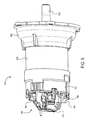
- Fig. 5 depicts a side view of an electric motor 510 including the brush assembly 100 described above, according to an embodiment.
- Fig. 6 depicts a cross-sectional view of the same motor 510.
- Motor 510 in an embodiment, includes a stator (or field can) 512 and an armature (or rotor) 514 disposed within the stator 512.
- the stator 512 may include, for example, a number of permanent magnets 513 affixed therein.
- An armature shaft 518 is secured to the rotor 514.
- a commutator 516 is mounted on the shaft 518 such that the armature 514, the commutator 516, and the shaft 528 are all rotatably coupled.
- a fan 502 is also mounted to another end of the shaft 518 and housed by a cup 504.
- brush assembly 100 is mounted on an end of the stator 512 such that the housing portion 125 partially covers an outer surface of the stator 512.
- the housing portion 125 may mate with an end of the stator 512 via, for example, screws or other fastening means.
- the brush holders 104 are in this manner arranged around the commutator 516, allowing the brushes 106 to make contact with the commutator 516.
- An end bearing 520 of the shaft 518 is housed within a bearing pocket 522 on an underside of the bridge portion 512 of the brush assembly 100.
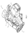
- Fig. 7 depicts a perspective view of a power tool 700 including the motor 510 described above, according to an embodiment.
- Power tool 700 in this example is a circular saw, though it should be understood that the circular saw is illustrated herein by way of example and the motor 510 of the invention with the brush assembly 100 described above may be utilized in any power tool, including, but not limited to, drills, impact drivers, miter saws, chop saws, grinders, hammer drills, cutters, nailers, etc.
- power tool 700 may be a DC (direct current) handheld electric tool having a housing 712 with a handle portion 702 accommodating a trigger switch 706 and a battery receiving portion 704.
- DC direct current
- the power tool 700 may alternatively be an AC (alternating current) power tool powered via an AC cord, or an AC/DC power tool.
- Power tool 700 further includes a motor cover 708 and a saw abrasive guard 710.
- Motor 510 is rotatable coupled to a saw disc housed within the guard 710.
- Fig. 8 depicts the same view of power tool 700, with the motor cover 708 removed for illustration purposes.
- the description of the invention is merely exemplary in nature and, thus, variations that do not depart from the gist of the invention are intended to be within the scope of the invention. Such variations are not to be regarded as a departure from the scope of the invention. It is noted that while the exemplary embodiment herein is described with reference to a four-pole brush assembly, the stop post of the present disclosure may be utilized with any brush assembly such as a two-pole brush assembly. Furthermore, it is noted that while the exemplary embodiment herein is described with reference to a two-piece brush holder, any type of brush holder such may be used in combination with the stop post.
Landscapes
- Engineering & Computer Science (AREA)
- Power Engineering (AREA)
- Motor Or Generator Current Collectors (AREA)
- Motor Or Generator Frames (AREA)
Abstract
Description
- This utility application claims the benefit of
U.S. Provisional Application No. 62/076,940 filed November 7, 2014 - The present disclosure relates to a brush assembly for electric motors, and more particularly to a brush assembly for motors used in electric power tools.
- The statements in this section merely provide background information related to the present disclosure and may not constitute prior art.
- Known portable power tools typically have an electric motor received within a tool housing. One common type of electric motor used in power tools has a rotor, a stator, and brushes. The rotor includes a rotor shaft, laminations mounted on the rotor shaft, armature windings wound in slots in the lamination stack, and a commutator mounted on the rotor shaft and electrically connected to the armature windings. The stator may have field windings wound in laminations, or may have permanent magnets. The brushes are mounted in brush housings, often known as brush boxes or brush holders, in sliding electrical contact with the commutator. Electric current is supplied from a power source through the brushes to the commutator, and from the commutator to the armature windings.
- The brushes and brush holders are typically part of a brush assembly(ies). The brush holders and brushes are disposed diametrically opposite to each other with the commutator disposed therebetween. The brush assembly(ies) includes springs that urge the brushes against the commutator. Exemplary brush assemblies may utilize two or four brushes around the commutator.
- Power tool are often used in harsh work environments and are susceptible to user drop and other impact. It is important to protect the internal components of the power tool, including the power tool motor, against damage in the event of drops.
- According to an embodiment of the invention, an electric motor is provided including: a stator, an armature rotatably received within the stator, where the armature includes an armature shaft on which a commutator is mounted, and a brush assembly. According to an embodiment, the brush assembly includes a brush card mount disposed around the commutator; a brush holder mounted on a surface of the brush card mount; a brush disposed within the brush holder in sliding contact with the commutator to supply electric current to the commutator; a torsion spring secured to the brush card mount adjacent the brush holder, the spring having a leg arranged to engage a back surface of the brush; and a spring stop post disposed proximate an outer periphery of the brush card mount to limit an outward movement of the leg of the spring away from the back surface of the brush.
- In an embodiment, the brush includes two curved surfaces with a groove formed therebetween. In an embodiment, a distal end of the leg of the spring engages the groove of the brush. In an embodiment, the distal end of the leg of the spring includes a hook engaging the groove of the brush.
- In an embodiment, a spring post is provided projecting from the brush card mount, wherein the spring includes a wound portion secured around the spring post. In an embodiment, the spring stop post is circumferentially located between the spring post and the brush holder within an angle formed between the brush holder and the spring post relative to a center of the brush card mount.
- In an embodiment, the spring stop post is provided substantially adjacent the leg of the spring and the spring stop post is engageable with a middle portion or distal end of the leg of the spring.
- In an embodiment, the brush holder includes an opening that is open-ended on a distal end of the brush holder and extends radially to accommodate the back and forth movement of the spring.
- In an embodiment, the brush assembly comprises four brush holders housing four brushes.
- In an embodiment, the brush assembly includes a housing portion substantially cylindrically shaped and extending from the brush card mount, the housing portion being arranged to mate with an end or around an outer surface of the motor stator.
- According to an embodiment, a power tool is provided including a housing and the electric motor described above.
-
Fig. 1 depicts a perspective side view of a brush assembly (also referred to herein as brush card), according to an embodiment; -
Fig. 2 depicts a top view of the brush card, according to an embodiment; -
Fig. 3 depicts a perspective view of a spring of the brush card, according to an embodiment; -
Fig. 4 depicts a perspective zoomed-in view of the brush and brush holder, according to an embodiment; -
Fig. 5 depicts a side view of an electric motor including the brush card, according to an embodiment; -
Fig. 6 depicts a cross-sectional view of the electric motor ofFig. 5 , according to an embodiment; -
Fig. 7 depicts a perspective view of a power tool having the electric motor, according to an embodiment; and -
Fig. 8 depicts the power tool ofFig. 7 with a motor cover removed, according to an embodiment. - Reference will now be made in detail to various aspects and embodiments of the invention, examples of which are illustrated in the accompanying drawings.
- A four-pole brush card for a power tool is described in detail in Patent Application No.
14/453,706, filed August 7, 2014 -
Figs. 1 and2 depict a brush assembly 100 (also referred to as brush card) according to an embodiment of the invention. In this embodiment, like the embodiments disclosed in Patent Application No.14/453,706 brush assembly 100 includes abrush card mount 102 and fourbrush holders 104. Thebrush card mount 102 has a substantially circular circumference and the fourbrush holders 104 are arranged equidistantly on four sides of thebrush card mount 102. Eachbrush holder 104 accommodates abrush 106 therein. Thebrushes 106 housed inbrush holders 104 facing each other are electrically connected to one another, as discussed below. Both ends of eachbrush holder 104 are open to allow radial movement of thebrush 106 towards and away from a center of thebrush card 100. Thebrush card mount 102 includesupright posts 108 in close proximity to thebrush holders 104. Eachpost 108 is arranged to hold a wound portion of aspring 110. Eachspring 110 includes an extended arm that engages a back surface ofbrush 106 inside thebrush holder 104 to bias thebrush 106 towards the center of thebrush card 100. - According to an embodiment,
brush card mount 102 includes aplanar portion 103, to whichbrush holders 104 are secured. A middle section of theplanar portion 103 includes an opening that receives a motor commutator (not shown). Thebrush card mount 102 also includes abridge portion 112 arranged above the commutator opening (and the commutator) and connected to the planar portion via fourbridge legs Bridge legs planar portion 103 to thebridge portion 112. Radially formed betweenbridge legs brushes 106. - In an embodiment, each
brush holder 104 includes two radial openings on its outer (vertical) walls. One radial opening is disposed adjacent thespring post 108 to allow thespring 110 to radially bias thebrush 106 toward the commutator. The other radial opening is to facilitate a wire connection to the brush. - According to an embodiment,
bridge leg bridge portion 112 to (or near) outer edges of thebrush card mount 102. In an embodiment, thebridge legs brush card mount 102. This arrangement strengthens support for thebridge portion 112. In addition,bridge leg 114a mechanically supports and electrically isolates two terminals 118a and 118b provided on both sides of its outward-extending wall. Terminals 118a and 118b are connected tometal routings bridge portion 112 to bridgeleg 114b.Metal routings brushes 106 facing each other to one of the terminals 118a and 118b. Specifically, ends ofmetal routings wires 122 to eithercorresponding brush holders 104 orbrushes 106. In an embodiment,metal routing 120a crosses overrouting 120b to allow foropposite brushes 106/brush holders 104 to be connected to the same terminal 118a or 118b. - In an embodiment, the brush assembly also includes a
housing portion 125 attached to thebrush card mount 102. Thehousing portion 125 may be provided as a separate piece, on which thebrush card mount 102 is mounted. Alternatively, thehousing portion 125 may be provided integrally with thebrush card mount 102 as a single molded piece. In an embodiment, housing portion is substantially cylindrical shaped, sized to mate with (or fit around) a motor stator. Alternatively thehousing portion 125 comprises a housing (i.e., can) for the entire motor assembly. -
Fig. 3 depicts aspring 110, according to an embodiment.Spring 110 includes awound portion 602, afirst leg 604, and asecond leg 606 that is longer than thefirst leg 604 and includes ahook 608 at its distal end. -
Fig. 4 depicts a perspective view of abrush 106 inside thebrush holder 104. In an embodiment, hook 608 of thespring 110 engages arecess 622 ofend portion 620 of thebrush holder 104 during the assembly process. Once the motor is fully assembled and the commutator is placed inside thebrush card 100, thehook 608 and thesecond leg 606 are pulled down to engage the rear surface of thebrush 106. - In an embodiment, the rear surface of the
brush 106 includes twohumped surfaces groove 628 therebetween. In an embodiment, thehook 608 is pulled down to engage thegroove 628 to complete the assembly process. In this embodiment, each thehumped surfaces 624 may be semi-circular shaped, although a cam surface may be utilized to optimize the movement of thehook 608 over thehumped surface 624. - It was found that in power tool application incorporating the
brush assembly 100 of the invention, the tip of thespring 110 would at times disengage thebrush 106 during drop tests. This is largely due to the relatively heavy mass of thebrush 106 overcoming thespring 104 force during impact. The In such circumstances, the spring may engage the brush or the brush holder at an incorrect position, or even dislocate out of position completely. - One obvious solution to this problem is to use springs with higher spring force. However this solution is not practical because the spring force should be optimized for effective motor commutation without damaging the brushes and prolonging the brush life.
- Referring back to
Figs. 1 and2 , in order to solve this problem, according to an embodiment of the invention, aspring stop post 130 is provided in the vicinity of eachbrush holder 104 to limit the movement of thespring 110 away from thebrush 106. In this embodiment, thestop post 130 is arranged near the outer periphery of thebrush card mount 102. Alternatively, stoppost 130 may project from thehousing portion 125 through slots on the outer periphery of thebrush card mount 120. Thestop post 130 is circumferentially located between thespring post 108 and the brush holder 104 (i.e., within the angle formed between thebrush holder 104 and thespring post 108 relative to the center of the brush assembly 100). In an embodiment, thestop post 130 is provided adjacent spring leg 606 (seeFig. 3 ) ofspring 110 to limit an outward movement ofspring leg 606. In an embodiment, thestop post 130 may come in contact with a middle portion or distal end of theleg 606 of thespring 110. - In an embodiment, the
stop post 130 blocks thespring 110 from backing out of its proper position relative to thebrush 106. In an embodiment, thestop post 130 limits the movement of thespring 110 too far out ofbrush groove 628. Specifically, thestop post 130 is positioned just close enough to thebrush holder 104 andspring 110 to allow thespring 110 to be moved into its proper position within thebrush groove 628 during motor assembly, but to also to limit movement of thespring 110 too far out of thebrush groove 628 in the event of a drop. In an embodiment,leg 606 of thespring 110 makes contact with thestop post 130 if theleg 606 moves too far radially from thebrush groove 628. It has been shown that during drop tests, the stop posts limits the radial movement of thespring 110 and forces thespring 110 to reengage thebrush groove 628. -
Fig. 5 depicts a side view of anelectric motor 510 including thebrush assembly 100 described above, according to an embodiment.Fig. 6 depicts a cross-sectional view of thesame motor 510.Motor 510, in an embodiment, includes a stator (or field can) 512 and an armature (or rotor) 514 disposed within thestator 512. Thestator 512 may include, for example, a number ofpermanent magnets 513 affixed therein. Anarmature shaft 518 is secured to therotor 514. Acommutator 516 is mounted on theshaft 518 such that thearmature 514, thecommutator 516, and the shaft 528 are all rotatably coupled. Afan 502 is also mounted to another end of theshaft 518 and housed by acup 504. - In an embodiment,
brush assembly 100 is mounted on an end of thestator 512 such that thehousing portion 125 partially covers an outer surface of thestator 512. Alternatively, thehousing portion 125 may mate with an end of thestator 512 via, for example, screws or other fastening means. Thebrush holders 104 are in this manner arranged around thecommutator 516, allowing thebrushes 106 to make contact with thecommutator 516. An end bearing 520 of theshaft 518 is housed within abearing pocket 522 on an underside of thebridge portion 512 of thebrush assembly 100. -
Fig. 7 depicts a perspective view of apower tool 700 including themotor 510 described above, according to an embodiment.Power tool 700 in this example is a circular saw, though it should be understood that the circular saw is illustrated herein by way of example and themotor 510 of the invention with thebrush assembly 100 described above may be utilized in any power tool, including, but not limited to, drills, impact drivers, miter saws, chop saws, grinders, hammer drills, cutters, nailers, etc. In an embodiment,power tool 700 may be a DC (direct current) handheld electric tool having ahousing 712 with ahandle portion 702 accommodating atrigger switch 706 and abattery receiving portion 704. It must be understood, however, that thepower tool 700 may alternatively be an AC (alternating current) power tool powered via an AC cord, or an AC/DC power tool.Power tool 700 further includes amotor cover 708 and a sawabrasive guard 710.Motor 510 is rotatable coupled to a saw disc housed within theguard 710.Fig. 8 depicts the same view ofpower tool 700, with themotor cover 708 removed for illustration purposes. - The description of the invention is merely exemplary in nature and, thus, variations that do not depart from the gist of the invention are intended to be within the scope of the invention. Such variations are not to be regarded as a departure from the scope of the invention. It is noted that while the exemplary embodiment herein is described with reference to a four-pole brush assembly, the stop post of the present disclosure may be utilized with any brush assembly such as a two-pole brush assembly. Furthermore, it is noted that while the exemplary embodiment herein is described with reference to a two-piece brush holder, any type of brush holder such may be used in combination with the stop post.
Claims (15)
- An electric motor comprising:a stator;an armature rotatably received within the stator, the armature having an armature shaft on which a commutator is mounted; anda brush assembly comprising:a brush card mount disposed around the commutator;a brush holder mounted on a surface of the brush card mount;a brush disposed within the brush holder in sliding contact with the commutator to supply electric current to the commutator;a torsion spring secured to the brush card mount adjacent the brush holder, the spring having a leg arranged to engage a back surface of the brush; anda spring stop post disposed proximate an outer periphery of the brush card mount to limit an outward movement of the leg of the spring away from the back surface of the brush.
- The electric motor of claim 1, wherein the brush includes two curved surfaces with a groove formed therebetween.
- The electric motor of claim 2, wherein a distal end of the leg of the spring engages the groove of the brush.
- The electric motor of claim 3, wherein the distal end of the leg of the spring comprises a hook engaging the groove of the brush.
- The electric motor of claim 1, further comprising a spring post projecting from the brush card mount, wherein the spring includes a wound portion secured around the spring post.
- The electric motor of claim 5, wherein the spring stop post is circumferentially located between the spring post and the brush holder within an angle formed between the brush holder and the spring post relative to a center of the brush card mount.
- The electric motor of claim 1, wherein the spring stop post is provided substantially adjacent the leg of the spring and the spring stop post is engageable with a middle portion or distal end of the leg of the spring.
- The electric motor of claim 1, wherein the brush holder includes an opening that is open-ended on a distal end of the brush holder and extends radially to accommodate the back and forth movement of the spring.
- The electric motor of claim 1, wherein the brush assembly comprises four brush holders housing four brushes.
- The electric motor of claim 1, further comprising a housing portion substantially cylindrically shaped and extending from the brush card mount, the housing portion being arranged to mate with an end or around an outer surface of the motor stator.
- A power tool comprising:a housing; andan electric motor disposed within the housing, the motor including: a stator;an armature rotatably received within the stator, the armature having an armature shaft on which a commutator is mounted; and a brush assembly,wherein the brush assembly comprises:a brush card mount disposed around the commutator;a brush holder mounted on a surface of the brush card mount;a brush disposed within the brush holder in sliding contact with the commutator to supply electric current to the commutator;a torsion spring secured to the brush card mount adjacent the brush holder, the spring having a leg arranged to engage a back surface of the brush; anda spring stop post disposed proximate an outer periphery of the brush card mount to limit an outward movement of the leg of the spring away from the back surface of the brush.
- The power tool of claim 11, wherein the brush includes two curved surfaces with a groove formed therebetween.
- The power tool of claim 12, wherein a distal end of the leg of the spring engages the groove of the brush.
- The power tool of claim 1, the brush assembly further comprising a spring post projecting from the brush card mount, wherein the spring includes a wound portion secured around the spring post, the spring stop post being circumferentially located between the spring post and the brush holder within an angle formed between the brush holder and the spring post relative to a center of the brush card mount.
- The power tool of claim 11, the brush assembly further comprising a housing portion substantially cylindrically shaped and extending from the brush card mount, the housing portion being arranged to mate with an end or around an outer surface of the motor stator.
Applications Claiming Priority (1)
| Application Number | Priority Date | Filing Date | Title |
|---|---|---|---|
| US201462076940P | 2014-11-07 | 2014-11-07 |
Publications (2)
| Publication Number | Publication Date |
|---|---|
| EP3018799A1 true EP3018799A1 (en) | 2016-05-11 |
| EP3018799B1 EP3018799B1 (en) | 2020-04-15 |
Family
ID=54477950
Family Applications (1)
| Application Number | Title | Priority Date | Filing Date |
|---|---|---|---|
| EP15193679.6A Active EP3018799B1 (en) | 2014-11-07 | 2015-11-09 | Spring post for brush card for a power tool |
Country Status (1)
| Country | Link |
|---|---|
| EP (1) | EP3018799B1 (en) |
Cited By (1)
| Publication number | Priority date | Publication date | Assignee | Title |
|---|---|---|---|---|
| CN117254627A (en) * | 2023-11-13 | 2023-12-19 | 苏州科义创智能科技有限公司 | AC brush motor |
Citations (5)
| Publication number | Priority date | Publication date | Assignee | Title |
|---|---|---|---|---|
| JPS6441689U (en) * | 1987-09-07 | 1989-03-13 | ||
| US20040245889A1 (en) * | 2002-02-28 | 2004-12-09 | Pts Corporation | Systems and methods for overcoming stiction |
| JP2008172943A (en) * | 2007-01-12 | 2008-07-24 | Kokusan Denki Co Ltd | Dc motor |
| US20080303358A1 (en) * | 2007-06-05 | 2008-12-11 | Axel Kuhnle | Electric power tool with a rotatable brush plate |
| EP2858220A1 (en) * | 2012-05-25 | 2015-04-08 | Mitsuba Corporation | Electric motor |
Family Cites Families (2)
| Publication number | Priority date | Publication date | Assignee | Title |
|---|---|---|---|---|
| US6133665A (en) * | 1998-08-14 | 2000-10-17 | S-B Power Tool Company | Brush system for electric motors |
| US6922003B2 (en) * | 2003-06-04 | 2005-07-26 | Asmo Co., Ltd. | Brush holder device for dynamoelectric machine |
-
2015
- 2015-11-09 EP EP15193679.6A patent/EP3018799B1/en active Active
Patent Citations (5)
| Publication number | Priority date | Publication date | Assignee | Title |
|---|---|---|---|---|
| JPS6441689U (en) * | 1987-09-07 | 1989-03-13 | ||
| US20040245889A1 (en) * | 2002-02-28 | 2004-12-09 | Pts Corporation | Systems and methods for overcoming stiction |
| JP2008172943A (en) * | 2007-01-12 | 2008-07-24 | Kokusan Denki Co Ltd | Dc motor |
| US20080303358A1 (en) * | 2007-06-05 | 2008-12-11 | Axel Kuhnle | Electric power tool with a rotatable brush plate |
| EP2858220A1 (en) * | 2012-05-25 | 2015-04-08 | Mitsuba Corporation | Electric motor |
Cited By (2)
| Publication number | Priority date | Publication date | Assignee | Title |
|---|---|---|---|---|
| CN117254627A (en) * | 2023-11-13 | 2023-12-19 | 苏州科义创智能科技有限公司 | AC brush motor |
| CN117254627B (en) * | 2023-11-13 | 2024-02-06 | 苏州科义创智能科技有限公司 | AC brush motor |
Also Published As
| Publication number | Publication date |
|---|---|
| EP3018799B1 (en) | 2020-04-15 |
Similar Documents
| Publication | Publication Date | Title |
|---|---|---|
| US20220166283A1 (en) | Brushless motor for a power tool | |
| US11646626B2 (en) | Brushless motor for a power tool | |
| EP3035508A2 (en) | Brushless motor assembly for a fastening tool | |
| US20170106521A1 (en) | Power tool | |
| US9991770B2 (en) | Spring post for brush card for a power tool | |
| CN104995701A (en) | Induction charging device | |
| EP1709723B1 (en) | Integrated brush-holder retention system | |
| US9143015B2 (en) | Brush holder for a brush assembly for a power tool motor | |
| WO2020255807A1 (en) | Electric motor and electric blower | |
| EP3018799B1 (en) | Spring post for brush card for a power tool | |
| US20090115266A1 (en) | Power tool with frameless motor and two-piece brush assembly, and method of assembly | |
| US10179387B2 (en) | Low height quarter sheet sander | |
| JP7149873B2 (en) | Electric tool | |
| US9866078B2 (en) | Brush assembly mount | |
| EP3386079A1 (en) | Motor and vehicle including same | |
| JP6082979B2 (en) | Commutator motor | |
| JP2007282490A (en) | Reversible rotary electric motor | |
| CN214124978U (en) | Electric toothbrush and motor thereof | |
| CN107210656B (en) | DC commutator motor | |
| JP2009071991A (en) | Brush device and electric motor provided with the same | |
| JP6127262B2 (en) | Commutator motor | |
| KR20130002818A (en) | Brush motor and assembly method thereof | |
| CN105429372A (en) | Motor connections for power tools |
Legal Events
| Date | Code | Title | Description |
|---|---|---|---|
| PUAI | Public reference made under article 153(3) epc to a published international application that has entered the european phase |
Free format text: ORIGINAL CODE: 0009012 |
|
| AK | Designated contracting states |
Kind code of ref document: A1 Designated state(s): AL AT BE BG CH CY CZ DE DK EE ES FI FR GB GR HR HU IE IS IT LI LT LU LV MC MK MT NL NO PL PT RO RS SE SI SK SM TR |
|
| AX | Request for extension of the european patent |
Extension state: BA ME |
|
| 17P | Request for examination filed |
Effective date: 20160525 |
|
| RBV | Designated contracting states (corrected) |
Designated state(s): AL AT BE BG CH CY CZ DE DK EE ES FI FR GB GR HR HU IE IS IT LI LT LU LV MC MK MT NL NO PL PT RO RS SE SI SK SM TR |
|
| STAA | Information on the status of an ep patent application or granted ep patent |
Free format text: STATUS: REQUEST FOR EXAMINATION WAS MADE |
|
| STAA | Information on the status of an ep patent application or granted ep patent |
Free format text: STATUS: EXAMINATION IS IN PROGRESS |
|
| 17Q | First examination report despatched |
Effective date: 20180306 |
|
| GRAP | Despatch of communication of intention to grant a patent |
Free format text: ORIGINAL CODE: EPIDOSNIGR1 |
|
| STAA | Information on the status of an ep patent application or granted ep patent |
Free format text: STATUS: GRANT OF PATENT IS INTENDED |
|
| INTG | Intention to grant announced |
Effective date: 20191128 |
|
| GRAS | Grant fee paid |
Free format text: ORIGINAL CODE: EPIDOSNIGR3 |
|
| GRAA | (expected) grant |
Free format text: ORIGINAL CODE: 0009210 |
|
| STAA | Information on the status of an ep patent application or granted ep patent |
Free format text: STATUS: THE PATENT HAS BEEN GRANTED |
|
| AK | Designated contracting states |
Kind code of ref document: B1 Designated state(s): AL AT BE BG CH CY CZ DE DK EE ES FI FR GB GR HR HU IE IS IT LI LT LU LV MC MK MT NL NO PL PT RO RS SE SI SK SM TR |
|
| REG | Reference to a national code |
Ref country code: CH Ref legal event code: EP |
|
| REG | Reference to a national code |
Ref country code: DE Ref legal event code: R096 Ref document number: 602015050642 Country of ref document: DE |
|
| REG | Reference to a national code |
Ref country code: IE Ref legal event code: FG4D |
|
| REG | Reference to a national code |
Ref country code: AT Ref legal event code: REF Ref document number: 1258452 Country of ref document: AT Kind code of ref document: T Effective date: 20200515 |
|
| REG | Reference to a national code |
Ref country code: NL Ref legal event code: MP Effective date: 20200415 |
|
| REG | Reference to a national code |
Ref country code: LT Ref legal event code: MG4D |
|
| PG25 | Lapsed in a contracting state [announced via postgrant information from national office to epo] |
Ref country code: NO Free format text: LAPSE BECAUSE OF FAILURE TO SUBMIT A TRANSLATION OF THE DESCRIPTION OR TO PAY THE FEE WITHIN THE PRESCRIBED TIME-LIMIT Effective date: 20200715 Ref country code: GR Free format text: LAPSE BECAUSE OF FAILURE TO SUBMIT A TRANSLATION OF THE DESCRIPTION OR TO PAY THE FEE WITHIN THE PRESCRIBED TIME-LIMIT Effective date: 20200716 Ref country code: PT Free format text: LAPSE BECAUSE OF FAILURE TO SUBMIT A TRANSLATION OF THE DESCRIPTION OR TO PAY THE FEE WITHIN THE PRESCRIBED TIME-LIMIT Effective date: 20200817 Ref country code: NL Free format text: LAPSE BECAUSE OF FAILURE TO SUBMIT A TRANSLATION OF THE DESCRIPTION OR TO PAY THE FEE WITHIN THE PRESCRIBED TIME-LIMIT Effective date: 20200415 Ref country code: LT Free format text: LAPSE BECAUSE OF FAILURE TO SUBMIT A TRANSLATION OF THE DESCRIPTION OR TO PAY THE FEE WITHIN THE PRESCRIBED TIME-LIMIT Effective date: 20200415 Ref country code: SE Free format text: LAPSE BECAUSE OF FAILURE TO SUBMIT A TRANSLATION OF THE DESCRIPTION OR TO PAY THE FEE WITHIN THE PRESCRIBED TIME-LIMIT Effective date: 20200415 Ref country code: IS Free format text: LAPSE BECAUSE OF FAILURE TO SUBMIT A TRANSLATION OF THE DESCRIPTION OR TO PAY THE FEE WITHIN THE PRESCRIBED TIME-LIMIT Effective date: 20200815 Ref country code: FI Free format text: LAPSE BECAUSE OF FAILURE TO SUBMIT A TRANSLATION OF THE DESCRIPTION OR TO PAY THE FEE WITHIN THE PRESCRIBED TIME-LIMIT Effective date: 20200415 |
|
| REG | Reference to a national code |
Ref country code: AT Ref legal event code: MK05 Ref document number: 1258452 Country of ref document: AT Kind code of ref document: T Effective date: 20200415 |
|
| PG25 | Lapsed in a contracting state [announced via postgrant information from national office to epo] |
Ref country code: HR Free format text: LAPSE BECAUSE OF FAILURE TO SUBMIT A TRANSLATION OF THE DESCRIPTION OR TO PAY THE FEE WITHIN THE PRESCRIBED TIME-LIMIT Effective date: 20200415 Ref country code: LV Free format text: LAPSE BECAUSE OF FAILURE TO SUBMIT A TRANSLATION OF THE DESCRIPTION OR TO PAY THE FEE WITHIN THE PRESCRIBED TIME-LIMIT Effective date: 20200415 Ref country code: BG Free format text: LAPSE BECAUSE OF FAILURE TO SUBMIT A TRANSLATION OF THE DESCRIPTION OR TO PAY THE FEE WITHIN THE PRESCRIBED TIME-LIMIT Effective date: 20200715 Ref country code: RS Free format text: LAPSE BECAUSE OF FAILURE TO SUBMIT A TRANSLATION OF THE DESCRIPTION OR TO PAY THE FEE WITHIN THE PRESCRIBED TIME-LIMIT Effective date: 20200415 |
|
| PG25 | Lapsed in a contracting state [announced via postgrant information from national office to epo] |
Ref country code: AL Free format text: LAPSE BECAUSE OF FAILURE TO SUBMIT A TRANSLATION OF THE DESCRIPTION OR TO PAY THE FEE WITHIN THE PRESCRIBED TIME-LIMIT Effective date: 20200415 |
|
| REG | Reference to a national code |
Ref country code: DE Ref legal event code: R097 Ref document number: 602015050642 Country of ref document: DE |
|
| PG25 | Lapsed in a contracting state [announced via postgrant information from national office to epo] |
Ref country code: ES Free format text: LAPSE BECAUSE OF FAILURE TO SUBMIT A TRANSLATION OF THE DESCRIPTION OR TO PAY THE FEE WITHIN THE PRESCRIBED TIME-LIMIT Effective date: 20200415 Ref country code: AT Free format text: LAPSE BECAUSE OF FAILURE TO SUBMIT A TRANSLATION OF THE DESCRIPTION OR TO PAY THE FEE WITHIN THE PRESCRIBED TIME-LIMIT Effective date: 20200415 Ref country code: CZ Free format text: LAPSE BECAUSE OF FAILURE TO SUBMIT A TRANSLATION OF THE DESCRIPTION OR TO PAY THE FEE WITHIN THE PRESCRIBED TIME-LIMIT Effective date: 20200415 Ref country code: RO Free format text: LAPSE BECAUSE OF FAILURE TO SUBMIT A TRANSLATION OF THE DESCRIPTION OR TO PAY THE FEE WITHIN THE PRESCRIBED TIME-LIMIT Effective date: 20200415 Ref country code: SM Free format text: LAPSE BECAUSE OF FAILURE TO SUBMIT A TRANSLATION OF THE DESCRIPTION OR TO PAY THE FEE WITHIN THE PRESCRIBED TIME-LIMIT Effective date: 20200415 Ref country code: EE Free format text: LAPSE BECAUSE OF FAILURE TO SUBMIT A TRANSLATION OF THE DESCRIPTION OR TO PAY THE FEE WITHIN THE PRESCRIBED TIME-LIMIT Effective date: 20200415 Ref country code: IT Free format text: LAPSE BECAUSE OF FAILURE TO SUBMIT A TRANSLATION OF THE DESCRIPTION OR TO PAY THE FEE WITHIN THE PRESCRIBED TIME-LIMIT Effective date: 20200415 Ref country code: DK Free format text: LAPSE BECAUSE OF FAILURE TO SUBMIT A TRANSLATION OF THE DESCRIPTION OR TO PAY THE FEE WITHIN THE PRESCRIBED TIME-LIMIT Effective date: 20200415 |
|
| PLBE | No opposition filed within time limit |
Free format text: ORIGINAL CODE: 0009261 |
|
| STAA | Information on the status of an ep patent application or granted ep patent |
Free format text: STATUS: NO OPPOSITION FILED WITHIN TIME LIMIT |
|
| PG25 | Lapsed in a contracting state [announced via postgrant information from national office to epo] |
Ref country code: SK Free format text: LAPSE BECAUSE OF FAILURE TO SUBMIT A TRANSLATION OF THE DESCRIPTION OR TO PAY THE FEE WITHIN THE PRESCRIBED TIME-LIMIT Effective date: 20200415 Ref country code: PL Free format text: LAPSE BECAUSE OF FAILURE TO SUBMIT A TRANSLATION OF THE DESCRIPTION OR TO PAY THE FEE WITHIN THE PRESCRIBED TIME-LIMIT Effective date: 20200415 |
|
| 26N | No opposition filed |
Effective date: 20210118 |
|
| PG25 | Lapsed in a contracting state [announced via postgrant information from national office to epo] |
Ref country code: SI Free format text: LAPSE BECAUSE OF FAILURE TO SUBMIT A TRANSLATION OF THE DESCRIPTION OR TO PAY THE FEE WITHIN THE PRESCRIBED TIME-LIMIT Effective date: 20200415 |
|
| PG25 | Lapsed in a contracting state [announced via postgrant information from national office to epo] |
Ref country code: MC Free format text: LAPSE BECAUSE OF FAILURE TO SUBMIT A TRANSLATION OF THE DESCRIPTION OR TO PAY THE FEE WITHIN THE PRESCRIBED TIME-LIMIT Effective date: 20200415 |
|
| REG | Reference to a national code |
Ref country code: CH Ref legal event code: PL |
|
| PG25 | Lapsed in a contracting state [announced via postgrant information from national office to epo] |
Ref country code: LU Free format text: LAPSE BECAUSE OF NON-PAYMENT OF DUE FEES Effective date: 20201109 |
|
| REG | Reference to a national code |
Ref country code: BE Ref legal event code: MM Effective date: 20201130 |
|
| PG25 | Lapsed in a contracting state [announced via postgrant information from national office to epo] |
Ref country code: CH Free format text: LAPSE BECAUSE OF NON-PAYMENT OF DUE FEES Effective date: 20201130 Ref country code: LI Free format text: LAPSE BECAUSE OF NON-PAYMENT OF DUE FEES Effective date: 20201130 |
|
| PG25 | Lapsed in a contracting state [announced via postgrant information from national office to epo] |
Ref country code: FR Free format text: LAPSE BECAUSE OF NON-PAYMENT OF DUE FEES Effective date: 20201130 Ref country code: IE Free format text: LAPSE BECAUSE OF NON-PAYMENT OF DUE FEES Effective date: 20201109 |
|
| PG25 | Lapsed in a contracting state [announced via postgrant information from national office to epo] |
Ref country code: TR Free format text: LAPSE BECAUSE OF FAILURE TO SUBMIT A TRANSLATION OF THE DESCRIPTION OR TO PAY THE FEE WITHIN THE PRESCRIBED TIME-LIMIT Effective date: 20200415 Ref country code: MT Free format text: LAPSE BECAUSE OF FAILURE TO SUBMIT A TRANSLATION OF THE DESCRIPTION OR TO PAY THE FEE WITHIN THE PRESCRIBED TIME-LIMIT Effective date: 20200415 Ref country code: CY Free format text: LAPSE BECAUSE OF FAILURE TO SUBMIT A TRANSLATION OF THE DESCRIPTION OR TO PAY THE FEE WITHIN THE PRESCRIBED TIME-LIMIT Effective date: 20200415 |
|
| PG25 | Lapsed in a contracting state [announced via postgrant information from national office to epo] |
Ref country code: MK Free format text: LAPSE BECAUSE OF FAILURE TO SUBMIT A TRANSLATION OF THE DESCRIPTION OR TO PAY THE FEE WITHIN THE PRESCRIBED TIME-LIMIT Effective date: 20200415 |
|
| PG25 | Lapsed in a contracting state [announced via postgrant information from national office to epo] |
Ref country code: BE Free format text: LAPSE BECAUSE OF NON-PAYMENT OF DUE FEES Effective date: 20201130 |
|
| PGFP | Annual fee paid to national office [announced via postgrant information from national office to epo] |
Ref country code: DE Payment date: 20251118 Year of fee payment: 11 |
|
| PGFP | Annual fee paid to national office [announced via postgrant information from national office to epo] |
Ref country code: GB Payment date: 20251120 Year of fee payment: 11 |