EP3018767B1 - Panel mount header connector - Google Patents
Panel mount header connector Download PDFInfo
- Publication number
- EP3018767B1 EP3018767B1 EP15192692.0A EP15192692A EP3018767B1 EP 3018767 B1 EP3018767 B1 EP 3018767B1 EP 15192692 A EP15192692 A EP 15192692A EP 3018767 B1 EP3018767 B1 EP 3018767B1
- Authority
- EP
- European Patent Office
- Prior art keywords
- panel
- latch
- housing
- latches
- mounting zone
- Prior art date
- Legal status (The legal status is an assumption and is not a legal conclusion. Google has not performed a legal analysis and makes no representation as to the accuracy of the status listed.)
- Active
Links
Images




Classifications
-
- G—PHYSICS
- G02—OPTICS
- G02B—OPTICAL ELEMENTS, SYSTEMS OR APPARATUS
- G02B6/00—Light guides; Structural details of arrangements comprising light guides and other optical elements, e.g. couplings
- G02B6/24—Coupling light guides
- G02B6/36—Mechanical coupling means
- G02B6/38—Mechanical coupling means having fibre to fibre mating means
- G02B6/3807—Dismountable connectors, i.e. comprising plugs
- G02B6/389—Dismountable connectors, i.e. comprising plugs characterised by the method of fastening connecting plugs and sockets, e.g. screw- or nut-lock, snap-in, bayonet type
- G02B6/3893—Push-pull type, e.g. snap-in, push-on
-
- H—ELECTRICITY
- H01—ELECTRIC ELEMENTS
- H01R—ELECTRICALLY-CONDUCTIVE CONNECTIONS; STRUCTURAL ASSOCIATIONS OF A PLURALITY OF MUTUALLY-INSULATED ELECTRICAL CONNECTING ELEMENTS; COUPLING DEVICES; CURRENT COLLECTORS
- H01R13/00—Details of coupling devices of the kinds covered by groups H01R12/70 or H01R24/00 - H01R33/00
- H01R13/73—Means for mounting coupling parts to apparatus or structures, e.g. to a wall
- H01R13/74—Means for mounting coupling parts in openings of a panel
- H01R13/741—Means for mounting coupling parts in openings of a panel using snap fastening means
- H01R13/743—Means for mounting coupling parts in openings of a panel using snap fastening means integral with the housing
-
- G—PHYSICS
- G02—OPTICS
- G02B—OPTICAL ELEMENTS, SYSTEMS OR APPARATUS
- G02B6/00—Light guides; Structural details of arrangements comprising light guides and other optical elements, e.g. couplings
- G02B6/24—Coupling light guides
- G02B6/36—Mechanical coupling means
- G02B6/38—Mechanical coupling means having fibre to fibre mating means
- G02B6/3807—Dismountable connectors, i.e. comprising plugs
- G02B6/3833—Details of mounting fibres in ferrules; Assembly methods; Manufacture
- G02B6/3834—Means for centering or aligning the light guide within the ferrule
-
- G—PHYSICS
- G02—OPTICS
- G02B—OPTICAL ELEMENTS, SYSTEMS OR APPARATUS
- G02B6/00—Light guides; Structural details of arrangements comprising light guides and other optical elements, e.g. couplings
- G02B6/24—Coupling light guides
- G02B6/42—Coupling light guides with opto-electronic elements
- G02B6/4201—Packages, e.g. shape, construction, internal or external details
- G02B6/4219—Mechanical fixtures for holding or positioning the elements relative to each other in the couplings; Alignment methods for the elements, e.g. measuring or observing methods especially used therefor
- G02B6/4228—Passive alignment, i.e. without a detection of the degree of coupling or the position of the elements
Definitions
- the subject matter herein relates generally to header connectors that are configured to mount to panels.
- header connectors are designed to mount to a panel to provide an electrical and/or optical connection across the panel.
- the panel may be a wall of an electrical device.
- the panel-mountable header connector is configured to extend at least partially through an opening in the panel and is secured to the panel.
- the panel-mountable header connectors are typically designed to accommodate only one panel thickness or a very narrow range of panel thicknesses.
- the opening in the panel may be cut to fit various sizes of connectors.
- a specific header connector is chosen from multiple different header connectors having the same mating interface, where each of the connectors is designed to accommodate a different thickness of panel.
- a need remains for a panel-mountable header connector that is configured to accommodate a broader range of panel thicknesses to avoid the need to determine which of multiple header connectors properly couples to a given panel.
- the problem to be solved is a need for reducing the surface area or footprint of the header connector on the panel in order to increase the number of panel-mount header connectors that may be installed in a given area of a panel.
- US 2010/0130059 discloses a lamp socket having a socket body provided with a flange. Reinforcement brackets extend between the flange and sides of the socket body, and latch sets extend from opposite sides of the socket body. Each latch set includes a first panel latch and a second panel latch. A free end of the second panel latch is disposed more proximate to the flange than a free end of the first panel latch.
- WO 2012/176939 discloses a connector having a connector housing and a waterproof grommet.
- the connector housing is provided with a flange and latches. Flexible pieces are located in a peripheral region of the flange, and the flexible pieces project from a surface of the flange.
- the grommet is mounted on the housing so that the flexible pieces engage the grommet.
- the grommet engages a rear side of the panel and the latches engage a front side of the panel.
- the grommet engaging the rear side of the panel causes the flexible pieces to be bent back.
- a panel-mountable header connector comprising: conductors configured to transmit at least one of electrical signals or optical signals; and a housing holding the conductors in a cavity of the housing, the housing having a front end and a rear end, the housing having a latch set and a stop feature, the latch set being located between the stop feature and the front end of the housing, and the stop feature being located between the latch set and the rear end of the housing, the latch set and the stop feature defining a panel mounting zone therebetween, the panel mounting zone configured to align with an opening in a panel when the housing is mounted to the panel, the latch set configured to engage a front side of the panel and the stop feature configured to engage a rear side of the panel to retain the panel in the panel mounting zone, the stop feature being a flange, the latch set being stepped such that a width of the panel mounting zone is variable to accommodate the panel having one of multiple thicknesses, wherein the latch set includes at least one first panel latch and at least one second panel latch, the latch set being stepped such that a width of
- the free end of the at least one second panel latch or the free end of the at least one first panel latch is configured to engage the front side of the panel to retain the panel in the panel mounting zone.
- Figure 1 is a perspective view of two panel mount header connectors 100 according to an arrangement included for background information.
- a first panel mount header connector 100A is shown mounted to a panel 102 and a second panel mount header connector 102B is shown poised for mounting to the panel 102.
- the first and second panel mount header connectors 102A, 102B may have the same or at least similar features, sizes, and shapes, such that the following description of a panel mount header connector 100 applies to both connectors 102A and 102B.
- the panel mount header connector 100 may be referred to as panel-mountable header connector 100, header connector 100, or connector 100.
- the header connector 100 includes a housing 104 and conductors 106.
- the conductors 106 may be optical fibers that convey optical signals and/or electrical contacts that convey electrical signals.
- the header connector 100 may be a fiber optic connector, an electrical connector, or a connector that includes both optical conductors and electrical conductors.
- the housing 104 holds the conductors 106 in a cavity 108 defined within the housing 104.
- the housing 104 has a first or front end 110 and a second or rear end 112 opposite the front end 110.
- the front end 110 defines a mating interface including an opening 114 to the cavity 108.
- the mating interface is configured to couple to a mating connector (not shown) to electrically and/or optically connect the conductors 106 to mating conductors (not shown) of the mating connector.
- the header connector 100 may be a plug that is configured to couple to a receptacle mating connector.
- the header connector 100 may be a receptacle that is configured to couple to a plug mating connector.
- the conductors 106 may be pin contacts or receptacle contacts that are configured to receive pin contacts.
- the rear end 112 of the header connector 100 may be terminated to one or more electrical or optical cables, wires, circuit boards, or the like.
- the header connector 100 includes a latch set 116 and a stop feature 118.
- the latch set 116 and the stop feature 118 define a panel mounting zone 120 therebetween.
- the panel mounting zone 120 is configured to align with an opening 122 in the panel 102 when the housing 104 is properly mounted to the panel 102.
- the latch set 116 is located between the stop feature 118 and the front end 110 of the housing 104
- the stop feature 118 is located between the latch set 116 and the rear end 112 of the housing 104.
- the latch set 116 is configured to engage a first or front side 124 of the panel 102 and the stop feature 118 is configured to engage a second or rear side 126 of the panel 102 in order to hold or retain the panel 102 in the panel mounting zone 120.
- the rear side 126 is opposite the front side 124.
- the latch set 116 may block relative movement between the panel 102 and the housing 104 that causes the panel 102 to move out of the panel mounting zone 120 towards the front end 110 of the housing 104
- the stop feature 118 may block relative movement that causes the panel 102 to move out of the panel mounting zone 120 towards the rear end 112.
- the header connector 100 is configured to mount properly to multiple different panel thicknesses, avoiding the need for manufacturing and/or purchasing multiple connectors that are each configured to mount to different panel thicknesses or different narrow ranges of panel thicknesses.
- the panel 102 may be a wall of an electrical device (not shown), a wall of a container that holds one or more devices therein, or a wall of another structure.
- the front side 124 of the panel 102 may be oriented towards an exterior of the device or container, and the rear side 126 may be oriented towards an interior of the device or container.
- the front side 124 is oriented towards the interior of the device or container, and the rear side 126 is oriented towards the exterior.
- relative or spatial terms such as “upper,” “lower,” “front,” “rear,” “top,” “bottom,” “left,” and “right” are only used to distinguish the referenced elements and do not necessarily require particular positions or orientations in the panel mount header connector 100 relative to gravity or relative to the surrounding environment of the panel mount header connector 100, such as relative to the device or container that includes the panel 102.
- the latch set 116 includes multiple latches 128 that extend from an outer surface 130 of the housing 104.
- the latches 128 are cantilevered such that each have a fixed end 132 at the outer surface 130 and a free end 134 that is not attached to the outer surface 130.
- the free ends 134 of the latches 128 define a front edge of the panel mounting zone 120 (for example, the edge of the panel mounting zone 120 proximate to the front end 110 of the housing 104).
- the latches 128 of the latch set 116 may be located on a common side of the housing 104 or on different sides of the housing 104.
- the housing 104 may include multiple latch sets 116.
- the stop feature 118 protrudes from the outer surface 130 of the housing 104.
- the stop feature 118 may include one or more components that define a front wall 136 that is configured to engage the rear side 126 of the panel 102.
- the front wall 136 defines a rear edge of the panel mounting zone 120 (for example, the edge of the panel mounting zone 120 proximate to the rear end 112 of the housing 104).
- the stop feature 118 includes multiple lugs 138 disposed at corners of the housing 104.
- the stop feature 118 may include only one lug 138, one or more wings (not shown), a flange, and/or the like.
- the housing 104 further includes a ramp 140 that escalates gradually from the outer surface 130 in the panel mounting zone 120 towards the rear end 112 of the housing 104.
- the ramp 140 is sloped such that an apex 142 of the ramp 140 is disposed more proximate to the rear end 112 of the housing 104 than a base 144 of the ramp 140 (for example, where the ramp 140 protrudes from the outer surface 130).
- the base 144 of the ramp 140 may be located in the panel mounting zone 120 between the free ends 134 of the latches 128 and the front wall 136 of the stop feature 118.
- the ramp 140 may be at least partially deflectable.
- the ramp 140 may be configured to apply a biasing force on the panel 102 towards the latches 128 of the latch set 116, as shown below with reference to Figures 3A-3C .
- the housing 104 is mounted to the panel 102 by inserting the housing 104, front end 110 first, through the opening 122 of the panel 102 in a loading direction 146 from the rear side 126 of the panel 102 to the front side 124 of the panel 102.
- the first panel mount header connector 100A is mounted to the panel 102
- the second panel mount header connector 100B is poised for mounting to the panel 102 through the opening 122 above the first header connector 100A. Since the front end 110 extends through the opening 122 first and the latch set 116 is disposed between the front end 110 and the panel mounting zone 120, the latches 128 of the latch set 116 are moved through the opening 122 to allow the panel mounting zone 120 to align with the panel 102.
- the latches 128 are configured to engage an edge of the panel 102 and to deflect inwards (towards the inner cavity 108 of the housing 104) as the latches 128 are inserted through the opening 122.
- the deflected latches 128 are biased such that the latches 128 undeflect once the free end 134 of the corresponding latch 128 moves beyond the front side 124 of the panel 102 and the deflecting force applied by the panel 102 on the latch 128 is removed.
- the header connector 100 may include one latch set 116 on a first side 148 of the housing 104 and a shelf 150 extending from an opposite, second side 152 of the housing 104.
- the first side 148 of the header connector 100B shown in Figure 1 is a top side
- the second side 152 of the header connector 100B is a bottom side.
- the shelf 150 may be a ridge that extends laterally at least partially across a width of the housing 104.
- the shelf 150 is configured to hook around the opening 122 of the panel 102 as the housing 104 is inserted into the opening 122 to allow the housing 104 to pivot about the shelf 150.
- the shelf 150 may be inserted through the opening 122 from the rear side 126, but engages a front edge 154 of the opening 122 at the front side 124 to allow the housing 104 to pivot about the front edge 154 as the housing 104 is loaded through the opening 122.
- the housing 104 may include a latch set 116 on each of the first side 148 and the second side 152 instead of including a shelf 150.
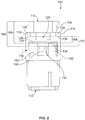
- FIG. 2 is a top view of the panel mount header connector 100 according to an arrangement included for background information.
- the latch set 116 includes at least one first or wide panel latch 160 and at least one second or narrow panel latch 162.
- wide panel latch and “narrow panel latch” do not describe or limit the sizes and/or shapes of the latches themselves, but rather identifies and contrasts characteristics of the panels that the respective latches are configured to engage.
- the wide panel latch 160 is configured to engage a panel that is wider or thicker than a panel that the narrow panel latch 162 is configured to engage.
- the wide panel latch 160 may be wider than, the same width as, or narrower than the narrow panel latch 162.
- each wide panel latch 160 is disposed at a different location relative to the rear end 112 of the housing 104 than the free end 134 of each narrow panel latch 162.
- the free end 134 of each wide panel latch 160 is a first distance 164 from the rear end 112, while the free end 134 of each narrow panel latch 162 is a second distance 166 from the rear end 112.
- the second distance 166 is shorter than the first distance 164, so the free end 134 of each narrow panel latch 162 is more proximate to the rear end 112 than the free end 134 of each wide panel latch 160.
- the latch set 116 is stepped because the free ends 134 of at least two of the latches 160, 162 in the latch set 116 are at staggered distances from the rear end 112 of the housing 104.
- the free end 134 of either the at least one wide panel latch 160 or the at least one narrow panel latch 162, but not both, is configured to engage the front side 124 (shown in Figure 1 ) of the panel 102 ( Figure 1 ) to retain the panel 102 in the panel mounting zone 120. Whether the at least one wide panel latch 160 or the at least one narrow panel latch 162 engages the front side 124 of the panel 102 depends on a thickness of the panel 102.
- the latch set 116 includes two narrow panel latches 162 and one wide panel latch 160 disposed laterally between the two narrow panel latches 162.
- the latches 160, 162 are disposed side-by-side and extend parallel to each other.
- the latches 160, 162 alternate in a lateral direction across a width of the header connector 100.
- the latch set 116 may include different numbers of wide panel latches 160 and/or narrow panel latches 162, such as only two or more than three total latches, and/or different arrangements or orientations of the latches.
- the stop feature 118 includes two lugs 138.
- the front walls 136 of the lugs 138 are an equal distance from the rear end 112 and define a constant rear edge of the panel mounting zone 120.
- the latch set 116 is stepped and defines multiple front edges of the panel mounting zone 120.
- the panel mounting zone 120 has multiple widths in order to accommodate a panel 102 (shown in Figure 1 ) having one of multiple thicknesses.
- the panel mounting zone 120 defined between the free ends 134 of the narrow panel latches 162 and the front walls 136 of the lugs 138 has a first width 168.
- the panel mounting zone 120 defined between the free end 134 of the wide panel latch 160 and the front walls 136 has a second width 170 that is wider than the first width 168. Therefore, a narrow panel 102 may align with the first width 168 of the panel mounting zone 120 between the narrow panel latches 162 and the lugs 138, where the free ends 134 of the narrow panel latches 162 engage the front side 124 (shown in Figure 1 ) of the panel 102. On the other hand, a wider panel 102 may align with the second, wider width 170 of the panel mounting zone 120 between the wide panel latch 160 and the lugs 138, where the free end 134 of the wide panel latch 160 engages the front side 124 of the panel 102.
- the header connector 100 may have three or more latches that have free ends at varying distances from the stop feature 118 and/or the rear end 112 in order to define a panel mounting zone 120 having at least three widths to accommodate three or more different panel thicknesses.
- Figures 3A-3C illustrate side cross-sections of a portion of the panel mount header connector 100 at various positions relative to the panel 102 according to an arrangement.
- the cross-section is taken through the wide panel latch 160 and the ramp 140.
- a stop feature 118 (such as the lug 138) is shown behind the ramp 140, and a narrow panel latch 162 is shown behind the wide panel latch 160.
- the header connector 100 is being inserted in the loading direction 146 through the opening 122 in the panel 102.
- An inner wall 180 of the panel 102 between the front side 124 and the rear side 126 engages the wide panel latch 160 and the narrow panel latch 162, causing the latches 160, 162 to deflect inward.
- the latches 160, 162 are shown in a deflected state.
- the ramp 140 is spaced apart from the panel 102 such that the ramp 140 does not engage the panel 102.
- the ramp 140 is undeflected in Figure 3A .
- the panel 102 is in the panel mounting zone 120 of the header connector 100.
- the free end 134 of the wide panel latch 160 has moved in the loading direction 146 beyond the front side 124 of the panel 102, so the deflecting force applied on the wide panel latch 160 by the inner wall 180 is removed.
- the wide panel latch 160 is biased towards an undeflected state, so the wide panel latch 160 in Figure 3B is in the undeflected state.
- a rear edge 182 of the panel 102 is the intersection between the rear side 126 and the inner wall 180. When the panel 102 is in the panel mounting zone 120, the rear edge 182 engages the ramp 140. The rear edge 182 may cause the ramp 140 to deflect at least partially inwards.
- the ramp 140 in Figure 3B has a reduced slope due to deflection of the ramp 140.
- the ramp 140 is biased in an undeflected state, so the ramp 140 applies a biasing force against the rear edge 182 of the panel 102 in a direction at least partially towards the free end 134 of the wide panel latch 160.
- the biasing force exerted by the ramp 140 may hold the front side 124 of the panel 102 in constant engagement with the free end 134 of the wide panel latch 160.
- the panel 102 may be sandwiched between the ramp 140 and the wide panel latch 160, which reduces the amount of relative movement (for example, rattling, vibration, etc.) between the panel 102 and the header connector 100.
- the front wall 136 of the stop feature 118 is spaced apart from the rear side 126 of the panel 102 by a small gap or tolerance 184.
- the stop feature 118 provides a hard stop that engages the rear side 126 to retain the panel 102 in the panel mounting zone 120 only when sufficient force is applied to the panel 102 or the connector 100 such that the rear edge 182 of the panel 102 deflects the ramp 140 to an extent that the gap 184 between the stop feature 118 and the panel 102 is eliminated.
- the panel 102 shown in Figure 3B has a first or wide thickness 186.
- the panel 102 is sufficiently wide that the free end 134 of the narrow panel latch 162 does not move past the inner wall 180 of the panel 102 as the header connector 100 is loaded before the ramp 140 and/or the stop feature 118 prevent further movement of the connector 100 in the loading direction 146 relative to the panel 102.
- the free end 134 of the narrow panel latch 162 remains deflected and in engagement with the inner wall 180 when the panel 102 has the wide thickness 186.
- the free end 134 of the narrow panel latch 162 does not engage the front side 124 of the panel 102 and is not used to retain the panel 102 in the panel mounting zone 120.
- the panel mounting zone 120 shown in Figure 3B has the width 170 that is defined between the front wall 136 of the stop feature 118 and the free end 134 of the wide panel latch 160.
- the panel 102 is in the panel mounting zone 120 of the header connector 100 similar to Figure 3B , but, unlike Figure 3B , the panel 102 in Figure 3C has a second or narrow thickness 188.
- the second thickness 188 is more narrow or less thick than the first thickness 186. Since the panel 102 is narrower than the panel 102 in Figure 3B , the free ends 134 of both the wide panel latch 160 and the narrow panel latch 162 move past or beyond the inner wall 180 of the panel 102 as the connector 100 is inserted through the panel 102 in the loading direction 146.
- both the wide panel latch 160 and the narrow panel latch 162 transition to the undeflected state when the panel 102 aligns with the panel mounting zone 120. Since the free end 134 of the narrow panel latch 162 is disposed more proximate to the rear end 112 (shown in Figure 2 ) of the housing 104, only the free end 134 of the narrow panel latch 162 engages the front side 124 of the panel 102 to retain the panel 102 in the panel mounting zone 120. For example, the free end 134 of the wide panel latch 160 is spaced apart from the panel 102 and does not engage the front side 124.
- the panel mounting zone 120 shown in Figure 3C has the width 168 that is defined between the front wall 136 of the stop feature 118 and the free end 134 of the narrow panel latch 162.
- the width 170 of the panel mounting zone 120 between the stop feature 118 and the wide panel latch 160 shown in Figure 3B may be configured to accommodate a range of panel thicknesses and not only one specific and limited thickness.
- the width 168 of the panel mounting zone 120 between the stop feature 118 and the narrow panel latch 162 shown in Figure 3C may be configured to accommodate a range of panel thicknesses and not only one specific and limited thickness.
- a range of panel thicknesses may be accommodated in each width 168, 170 of the panel mounting zone 120.
- a range of wide panel thicknesses may be accommodated between the stop feature 118 and the wide panel latch 160, and a different range of narrow panel thicknesses may be accommodated between the stop feature 118 and the narrow panel latch 162.
- the thicknesses in the range of wide panel thicknesses may be greater than the thicknesses in the range of narrow panel thicknesses.
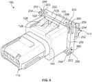
- FIG 4 is a perspective view of the panel mount header connector 100 according to the invention.
- the latches 128 may be similar to the latches 128 shown in Figure 1 .
- the stop feature is a flange 252.
- the flange 252 extends from the outer surface 130 of the housing 104.
- the flange 252 includes at least one biasing segment 253 along a front wall 256 of the flange 252.
- the flange 252 includes biasing segments 253 at corners 258 of the flange 252.
- Each biasing segment 253 includes a lug 254 that protrudes from the front wall 256.
- the at least one biasing segment 253 of the flange 252 defines at least one aperture 260 that is axially rearward (for example, towards the rear end 112) of the front wall 256.
- the at least one aperture 260 may be multiple apertures 260 that are each disposed along a different corner 258 of the flange 252 or may be a single aperture that extends along the entire perimeter of the flange 252.
- the lugs 254 are at least partially deflectable and are configured to flex rearward at least partially into the at least one aperture 260.
- the lugs 254 are configured to engage the rear side 126 ( Figure 1 ) of the panel 102 and to deflect at least partially into the at least one aperture 260 to apply a biasing force on the panel 102 towards the latches 128. Due to the amount of deflection of the lugs 254, the rear edge of the panel mounting zone 120 is defined by the lugs 254 or the front wall 256 of the flange 252. For example, the lugs 254 provide a variable stop and the front wall 256 provides a hard stop. The front wall 256 defines the rear edge of the panel mounting zone 120 if the lugs 254 deflect rearward beyond the plane of the front wall 256.
- Figure 5 is a perspective view of the panel mount header connector 100 according to an arrangement included for background information only.
- Figure 6 is a top view of the panel mount header connector 100 shown in Figure 5.
- Figure 7 is a perspective view of the panel mount header connector 100 shown in Figures 5 and 6 mounted to a panel 102.
- the header connector 100 shown in Figures 5-7 defines the panel mounting zone 120 between the latch set 116 and the stop feature 118, like the header connector 100 shown in Figure 1 .
- the latch set 116 includes at least a first latch 202 that extends from a first or left side 204 of the housing 104 and a second latch 206 that extends from a second or right side 208 of the housing 104.
- the right side 208 is opposite the left side 204.
- Free ends 134 of the first and second latches 202, 206 are configured to engage a front side 124 of the panel 102. As shown in Figure 6 , the free ends 134 of the first and second latches 202, 206 are disposed an equal distance 210 from the rear end 112 of the housing 104, and define a constant first or front edge of the panel mounting zone 120.
- the stop feature 118 is stepped to define multiple widths of the panel mounting zone 120 to accommodate the panel 102 having one of multiple panel thicknesses.
- the stop feature 118 may be a stepped flange 212 that has at least a first ledge 214 and a second ledge 216.
- the second ledge 216 is stepped from the first ledge 214 such that the second ledge 216 is disposed more proximate to the rear end 112 of the housing 104 than the first ledge 214.
- the first ledge 214 or the second ledge 216 is configured to engage the rear side 126 of the panel 102 to retain the panel 102 in the panel mounting zone 120.
- the stepped flange 212 defines a variable rear edge of the panel mounting zone 120.
- the first ledge 214 is more proximate to the free ends 134 of the latches 202, 206 along a longitudinal axis 218 of the header connector 100 than the second ledge 216.
- the first ledge 214 defines a narrow width of the panel mounting zone 120 for accommodating panels having narrow thicknesses.
- the second ledge 216 defines a wide width of the panel mounting zone 120 for accommodating panels having wide thicknesses (relative to the narrow panels accommodated by the narrow width of the panel mounting zone 120).
- the latches 202, 206 extend from the left and right sides 204, 208, respectively, of the housing 104, and the stepped flange 212 extends from a third or top side 220 and a fourth or bottom side 222 of the housing 104.
- the bottom side 222 is opposite the top side 220.
- the top and bottom sides 220, 222 are between the left and right sides 204, 208 and between the front and rear ends 110, 112.
- the housing 104 may include left and right arms 224, 226 that extend from the left and right sides 204, 208, respectively, of the housing 104.
- the left and right arms 224 extend generally towards the front end 110 such that a fixed end 228 of each of the arms 224, 226 is more proximate to the rear end 112 and a free end 230 of each of the arms 224, 226 is more proximate to the front end 110.
- the left latch 202 extends from the left arm 224, and the right latch 206 extends from the right arm 226.
- the free ends 134 of the latches 202, 206 are disposed more proximate to the rear end 112 than the fixed ends 132.
- the free end 134 of the left latch 202 extends outward to the left from the left arm 224, and, similarly, the free end 134 of the right latch 206 extends outward to the right from the right arm 226.
- the left and right arms 224, 226 are separated from a body 232 of the housing 104, which defines the cavity 108 (shown in Figure 1 ) and holds the conductors 106 ( Figure 1 ), by slots 234.
- the left and right arms 224, 226 including the left and right latches 202, 206 thereon
- the latches 202, 206 and/or the arms 224, 226 deflect at least partially inwards towards the body 232, reducing the size of the slots 234, due to interference between inner surfaces of the panel 102 with the latches 202, 206 and/or the arms 224, 226.
- the free ends 134 of the latches 202, 206 move beyond the front side 124 of the panel 102, the deflecting force is removed, and the latches 202, 206 and/or the arms 224, 226 return to an undeflected state. In the undeflected state, the free ends 134 are configured to engage the front side 124 to retain the panel 102 in the panel mounting zone 120.
- a latch reinforcement band 236 may be inserted into the slots 234 between the body 232 and the left and right arms 224, 226.
- the latch reinforcement band 236 may be a pre-formed component or a wrapped component, such as a cable tie.
- the latch reinforcement band 236 is configured to mechanically block the arms 224, 226 and/or the latches 202, 206 on the arms 224, 226 from deflecting inwards into the slots 234.
- the latch reinforcement band 236 may prevent the arms 224, 226 and/or latches 202, 206 from deflecting to an extent that allows the free ends 134 of the latches 202, 206 to disengage from the front side 124 and enter the opening 122 of the panel 102, which uncouples the header connector 100 from the panel 102.
- the latch reinforcement band 236 may prevent or at least prohibit unintentional removal of the header connector 100 from the panel 102.
- Figures 8A and 8B are side cross-sectional views of the header connector 100 shown in Figures 5-7 mounted to panels 102 of two different thicknesses.
- the stop feature 118 is the stepped flange 212 that extends upward from the top side 220 of the housing 104 and downward from the bottom side 222 of the housing 104. Since the cross-sections are side views, the latches 202, 206 (shown in Figure 5 ) that extend from the left and right sides 204, 208, ( Figure 5 ) respectively, of the housing 104 are not shown.
- the free ends 134 ( Figure 5 ) of the latches 202, 206 are assumed to be in contact with or at least proximate to the front side 124 of the panels 102 in Figures 8A and 8B to retain the corresponding panels 102 in the respective panel mounting zones 120.
- the header connector 100 in Figure 8A is mounted to a panel 102 having a narrow thickness 240. Since the panel 102 is narrow, the rear side 126 of the panel 102 engages the first ledge 214 of the stepped flange 212 to retain the panel 102 in the panel mounting zone 120. The second ledge 216 that is stepped back from the first ledge 214 is spaced apart from and does not engage the rear side 126.
- a gasket 244 may be placed around the stepped flange 212 to seal the header connector 100 to the panel 102, such as to prevent or at least prohibit contaminants and/or electromagnetic interference (EMI) from penetrating the panel 102 through the opening 122.
- EMI electromagnetic interference
- the header connector 100 in Figure 8B is mounted to a panel 102 having a wide thickness 242. Since the panel 102 is wide, the rear side 126 of the panel 102 engages the second ledge 216 of the stepped flange 212 to retain the panel 102 in the panel mounting zone 120.
- the first ledge 214 is disposed within the opening 122 of the panel 102 and does not engage the rear side 126 of the panel 102.
- the panels 102 shown in Figures 8A and 8B engage different ledges 214, 216 of the stepped flange 212 because the openings 122 have different dimensions.
- the opening 122 of the narrow panel 102 shown in Figure 8A has a height 248 that is smaller or shorter than a height 250 of the opening 122 of the wide panel 102 shown in Figure 8B . Therefore, since the locations of the free ends 134 (shown in Figure 8 ) of the latches 202, 206 ( Figure 8 ) are constant or fixed (relative to the rear end 112), panels 102 of different thicknesses are received in the panel mounting zone 120 by engaging different ledges 214, 216 of the stepped flange 212.
- the dimensions (for example, height) of the openings 122 in the panels 102 may be determined based on the thickness of the panel 102 to allow the panel 102 to align with an appropriate one of the ledges 214, 216.
- the first and second ledges 214, 216 may each be configured to accommodate a range of panel thicknesses, with the thicknesses of the range accommodated by the second ledge 216 being greater or wider than the thicknesses of the range accommodated by the first ledge 214.
- the stepped flange 212 further includes a third ledge 246 that is stepped from the second ledge 216 and disposed more proximate to the rear end 112 of the housing 104 than the second ledge 216.
- the third ledge 246 is also a farther distance from the cavity 108 than the second ledge 216.
- the third ledge 246 is configured to engage the rear side 126 of the panel 102 if the panel 102 has an extra wide thickness (for example, wider than the range of panel thicknesses accommodated by the second ledge 216).
- the opening 122 must be cut large enough such that both the first and second ledges 214, 216 are disposed within the opening 122.
- the third ledge 246 may be used to engage the gasket 244 when the panel 102 is narrow enough that the first ledge 214 or the second ledge 216 defines the panel mounting zone 120.
- the stepped ledge 212 may include more than three ledges or less than three ledges.
Landscapes
- Physics & Mathematics (AREA)
- General Physics & Mathematics (AREA)
- Optics & Photonics (AREA)
- Details Of Connecting Devices For Male And Female Coupling (AREA)
- Mechanical Coupling Of Light Guides (AREA)
- Connector Housings Or Holding Contact Members (AREA)
Description
- The subject matter herein relates generally to header connectors that are configured to mount to panels.
- Some header connectors are designed to mount to a panel to provide an electrical and/or optical connection across the panel. For example, the panel may be a wall of an electrical device. The panel-mountable header connector is configured to extend at least partially through an opening in the panel and is secured to the panel. The panel-mountable header connectors are typically designed to accommodate only one panel thickness or a very narrow range of panel thicknesses. Typically, the opening in the panel may be cut to fit various sizes of connectors. However, it is much more difficult and expensive to alter a thickness of the panel to attain a thickness that a desired header connector is designed to accommodate. Generally, to accommodate various panel thicknesses, a specific header connector is chosen from multiple different header connectors having the same mating interface, where each of the connectors is designed to accommodate a different thickness of panel. A need remains for a panel-mountable header connector that is configured to accommodate a broader range of panel thicknesses to avoid the need to determine which of multiple header connectors properly couples to a given panel.
- In addition, due to the trend of increasing signal density (or amount of electrical and/or optical connections per area) in electrical and/or optical systems, the problem to be solved is a need for reducing the surface area or footprint of the header connector on the panel in order to increase the number of panel-mount header connectors that may be installed in a given area of a panel.
-
US 2010/0130059 , on which the preamble ofclaim 1 is based, discloses a lamp socket having a socket body provided with a flange. Reinforcement brackets extend between the flange and sides of the socket body, and latch sets extend from opposite sides of the socket body. Each latch set includes a first panel latch and a second panel latch. A free end of the second panel latch is disposed more proximate to the flange than a free end of the first panel latch. When the socket body is mounted to a panel, the socket body is inserted into an opening in the panel so that the flange engages a rear side of the panel. When the socket body is mounted to a thin panel, the free end of the second panel latch engages a front side of the panel and when the socket body is mounted to a thick panel, the free end of the first panel latch engages the front side of the panel. -
WO 2012/176939 discloses a connector having a connector housing and a waterproof grommet. The connector housing is provided with a flange and latches. Flexible pieces are located in a peripheral region of the flange, and the flexible pieces project from a surface of the flange. The grommet is mounted on the housing so that the flexible pieces engage the grommet. When the connector is mounted to a thin panel, the grommet engages a rear side of the panel and the latches engage a front side of the panel. When the connector is mounted to a thick panel, the grommet engaging the rear side of the panel causes the flexible pieces to be bent back. - The solution to the problem is provided by a panel-mountable header connector comprising: conductors configured to transmit at least one of electrical signals or optical signals; and a housing holding the conductors in a cavity of the housing, the housing having a front end and a rear end, the housing having a latch set and a stop feature, the latch set being located between the stop feature and the front end of the housing, and the stop feature being located between the latch set and the rear end of the housing, the latch set and the stop feature defining a panel mounting zone therebetween, the panel mounting zone configured to align with an opening in a panel when the housing is mounted to the panel, the latch set configured to engage a front side of the panel and the stop feature configured to engage a rear side of the panel to retain the panel in the panel mounting zone, the stop feature being a flange, the latch set being stepped such that a width of the panel mounting zone is variable to accommodate the panel having one of multiple thicknesses, wherein the latch set includes at least one first panel latch and at least one second panel latch, the latch set being stepped such that a free end of the at least one second panel latch is disposed more proximate to the rear end of the housing than a free end of the at least one first panel latch, the free end of the at least one second panel latch or the free end of the at least one first panel latch being configured to engage the front side of the panel, characterized in that the flange includes at least one biasing segment along a front wall of the flange, the or each biasing segment including a lug that protrudes from the front wall, the at least one biasing segment defining at least one aperture that is axially rearward of the front wall, the at least one lug being at least partially deflectable and being configured to flex rearward at least partially into the at least one aperture, wherein when the connector is mounted to the panel, the at least one lug is configured to engage the rear side of the panel and to deflect at least partially into the at least one aperture to apply a biasing force on the panel towards the latch set.
- Thus, based on a thickness of the panel, the free end of the at least one second panel latch or the free end of the at least one first panel latch is configured to engage the front side of the panel to retain the panel in the panel mounting zone.
- The invention will now be described by way of example with reference to the accompanying drawings in which:
-
Figure 1 is a perspective view of two panel mount header connectors according to an arrangement included for background information; -
Figure 2 is a top view of a said panel mount header connector according to an arrangement included for background information; -
Figures 3A-3C illustrate side cross-sections of a portion of the panel mount header connector at various positions relative to the panel according to an arrangement included for background information; -
Figure 4 is a perspective view of the panel mount header connector according to the invention; -
Figure 5 is a perspective view of the panel mount header connector according to an arrangement included for background information only; -
Figure 6 is a top view of the panel mount header connector shown inFigure 5 ; -
Figure 7 is a perspective view of the panel mount header connector shown inFigures 5 and 6 mounted to a panel; and -
Figures 8A and 8B are side cross-sectional views of the header connector shown inFigures 5-7 mounted to panels of two different thicknesses. -
Figure 1 is a perspective view of two panelmount header connectors 100 according to an arrangement included for background information. A first panelmount header connector 100A is shown mounted to apanel 102 and a second panel mount header connector 102B is shown poised for mounting to thepanel 102. The first and second panel mount header connectors 102A, 102B may have the same or at least similar features, sizes, and shapes, such that the following description of a panelmount header connector 100 applies to both connectors 102A and 102B. As used herein, the panelmount header connector 100 may be referred to as panel-mountable header connector 100,header connector 100, orconnector 100. - The
header connector 100 includes ahousing 104 andconductors 106. Theconductors 106 may be optical fibers that convey optical signals and/or electrical contacts that convey electrical signals. For example, theheader connector 100 may be a fiber optic connector, an electrical connector, or a connector that includes both optical conductors and electrical conductors. Thehousing 104 holds theconductors 106 in acavity 108 defined within thehousing 104. Thehousing 104 has a first orfront end 110 and a second orrear end 112 opposite thefront end 110. Thefront end 110 defines a mating interface including anopening 114 to thecavity 108. The mating interface is configured to couple to a mating connector (not shown) to electrically and/or optically connect theconductors 106 to mating conductors (not shown) of the mating connector. For example, theheader connector 100 may be a plug that is configured to couple to a receptacle mating connector. Alternatively, theheader connector 100 may be a receptacle that is configured to couple to a plug mating connector. Theconductors 106 may be pin contacts or receptacle contacts that are configured to receive pin contacts. Therear end 112 of theheader connector 100 may be terminated to one or more electrical or optical cables, wires, circuit boards, or the like. - The
header connector 100 includes alatch set 116 and astop feature 118. The latch set 116 and thestop feature 118 define apanel mounting zone 120 therebetween. Thepanel mounting zone 120 is configured to align with anopening 122 in thepanel 102 when thehousing 104 is properly mounted to thepanel 102. In an arrangement, thelatch set 116 is located between thestop feature 118 and thefront end 110 of thehousing 104, and thestop feature 118 is located between thelatch set 116 and therear end 112 of thehousing 104. When theopening 122 of thepanel 102 is aligned with thepanel mounting zone 120, thelatch set 116 is to the front of thepanel 102 and thestop feature 118 is to the rear of thepanel 102. Thelatch set 116 is configured to engage a first orfront side 124 of thepanel 102 and thestop feature 118 is configured to engage a second orrear side 126 of thepanel 102 in order to hold or retain thepanel 102 in thepanel mounting zone 120. Therear side 126 is opposite thefront side 124. For example, thelatch set 116 may block relative movement between thepanel 102 and thehousing 104 that causes thepanel 102 to move out of thepanel mounting zone 120 towards thefront end 110 of thehousing 104, and thestop feature 118 may block relative movement that causes thepanel 102 to move out of thepanel mounting zone 120 towards therear end 112. In an exemplary arrangement, at least one of the latch set 116 or thestop feature 118 are stepped such that a width of thepanel mounting zone 120 is variable to accommodate thepanel 102 having different thicknesses. As a result, theheader connector 100 is configured to mount properly to multiple different panel thicknesses, avoiding the need for manufacturing and/or purchasing multiple connectors that are each configured to mount to different panel thicknesses or different narrow ranges of panel thicknesses. - The
panel 102 may be a wall of an electrical device (not shown), a wall of a container that holds one or more devices therein, or a wall of another structure. Thefront side 124 of thepanel 102 may be oriented towards an exterior of the device or container, and therear side 126 may be oriented towards an interior of the device or container. Alternatively, thefront side 124 is oriented towards the interior of the device or container, and therear side 126 is oriented towards the exterior. As used herein, relative or spatial terms such as "upper," "lower," "front," "rear," "top," "bottom," "left," and "right" are only used to distinguish the referenced elements and do not necessarily require particular positions or orientations in the panelmount header connector 100 relative to gravity or relative to the surrounding environment of the panelmount header connector 100, such as relative to the device or container that includes thepanel 102. - The latch set 116 includes
multiple latches 128 that extend from anouter surface 130 of thehousing 104. Thelatches 128 are cantilevered such that each have a fixedend 132 at theouter surface 130 and afree end 134 that is not attached to theouter surface 130. In an arrangement, thefree ends 134 of thelatches 128 define a front edge of the panel mounting zone 120 (for example, the edge of thepanel mounting zone 120 proximate to thefront end 110 of the housing 104). Thelatches 128 of the latch set 116 may be located on a common side of thehousing 104 or on different sides of thehousing 104. In addition, thehousing 104 may include multiple latch sets 116. - The
stop feature 118 protrudes from theouter surface 130 of thehousing 104. Thestop feature 118 may include one or more components that define afront wall 136 that is configured to engage therear side 126 of thepanel 102. For example, thefront wall 136 defines a rear edge of the panel mounting zone 120 (for example, the edge of thepanel mounting zone 120 proximate to therear end 112 of the housing 104). In the illustrated arrangement, thestop feature 118 includesmultiple lugs 138 disposed at corners of thehousing 104. In alternative arrangements, thestop feature 118 may include only onelug 138, one or more wings (not shown), a flange, and/or the like. - In an arrangement, the
housing 104 further includes aramp 140 that escalates gradually from theouter surface 130 in thepanel mounting zone 120 towards therear end 112 of thehousing 104. Theramp 140 is sloped such that an apex 142 of theramp 140 is disposed more proximate to therear end 112 of thehousing 104 than abase 144 of the ramp 140 (for example, where theramp 140 protrudes from the outer surface 130). Thebase 144 of theramp 140 may be located in thepanel mounting zone 120 between the free ends 134 of thelatches 128 and thefront wall 136 of thestop feature 118. Theramp 140 may be at least partially deflectable. For example, theramp 140 may be configured to apply a biasing force on thepanel 102 towards thelatches 128 of the latch set 116, as shown below with reference toFigures 3A-3C . - In an arrangement, the
housing 104 is mounted to thepanel 102 by inserting thehousing 104,front end 110 first, through theopening 122 of thepanel 102 in aloading direction 146 from therear side 126 of thepanel 102 to thefront side 124 of thepanel 102. As shown inFigure 1 , the first panelmount header connector 100A is mounted to thepanel 102, while the second panelmount header connector 100B is poised for mounting to thepanel 102 through theopening 122 above thefirst header connector 100A. Since thefront end 110 extends through theopening 122 first and the latch set 116 is disposed between thefront end 110 and thepanel mounting zone 120, thelatches 128 of the latch set 116 are moved through theopening 122 to allow thepanel mounting zone 120 to align with thepanel 102. Thelatches 128 are configured to engage an edge of thepanel 102 and to deflect inwards (towards theinner cavity 108 of the housing 104) as thelatches 128 are inserted through theopening 122. The deflected latches 128 are biased such that thelatches 128 undeflect once thefree end 134 of thecorresponding latch 128 moves beyond thefront side 124 of thepanel 102 and the deflecting force applied by thepanel 102 on thelatch 128 is removed. - Optionally, the
header connector 100 may include one latch set 116 on afirst side 148 of thehousing 104 and ashelf 150 extending from an opposite,second side 152 of thehousing 104. Thefirst side 148 of theheader connector 100B shown inFigure 1 is a top side, and thesecond side 152 of theheader connector 100B is a bottom side. Theshelf 150 may be a ridge that extends laterally at least partially across a width of thehousing 104. Theshelf 150 is configured to hook around theopening 122 of thepanel 102 as thehousing 104 is inserted into theopening 122 to allow thehousing 104 to pivot about theshelf 150. For example, theshelf 150 may be inserted through the opening 122 from therear side 126, but engages afront edge 154 of theopening 122 at thefront side 124 to allow thehousing 104 to pivot about thefront edge 154 as thehousing 104 is loaded through theopening 122. In an alternative arrangement, thehousing 104 may include alatch set 116 on each of thefirst side 148 and thesecond side 152 instead of including ashelf 150. -
Figure 2 is a top view of the panelmount header connector 100 according to an arrangement included for background information. The latch set 116 includes at least one first orwide panel latch 160 and at least one second ornarrow panel latch 162. As used herein, "wide panel latch" and "narrow panel latch" do not describe or limit the sizes and/or shapes of the latches themselves, but rather identifies and contrasts characteristics of the panels that the respective latches are configured to engage. For example, thewide panel latch 160 is configured to engage a panel that is wider or thicker than a panel that thenarrow panel latch 162 is configured to engage. In addition, thewide panel latch 160 may be wider than, the same width as, or narrower than thenarrow panel latch 162. - The
free end 134 of eachwide panel latch 160 is disposed at a different location relative to therear end 112 of thehousing 104 than thefree end 134 of eachnarrow panel latch 162. For example, thefree end 134 of eachwide panel latch 160 is afirst distance 164 from therear end 112, while thefree end 134 of eachnarrow panel latch 162 is asecond distance 166 from therear end 112. Thesecond distance 166 is shorter than thefirst distance 164, so thefree end 134 of eachnarrow panel latch 162 is more proximate to therear end 112 than thefree end 134 of eachwide panel latch 160. Thus, the latch set 116 is stepped because the free ends 134 of at least two of thelatches rear end 112 of thehousing 104. In an arrangement, thefree end 134 of either the at least onewide panel latch 160 or the at least onenarrow panel latch 162, but not both, is configured to engage the front side 124 (shown inFigure 1 ) of the panel 102 (Figure 1 ) to retain thepanel 102 in thepanel mounting zone 120. Whether the at least onewide panel latch 160 or the at least onenarrow panel latch 162 engages thefront side 124 of thepanel 102 depends on a thickness of thepanel 102. - In the illustrated arrangement, the latch set 116 includes two narrow panel latches 162 and one
wide panel latch 160 disposed laterally between the two narrow panel latches 162. Thelatches latches header connector 100. In other arrangements, the latch set 116 may include different numbers of wide panel latches 160 and/or narrow panel latches 162, such as only two or more than three total latches, and/or different arrangements or orientations of the latches. - The
stop feature 118 includes twolugs 138. Thefront walls 136 of thelugs 138 are an equal distance from therear end 112 and define a constant rear edge of thepanel mounting zone 120. On the other hand, the latch set 116 is stepped and defines multiple front edges of thepanel mounting zone 120. Thus, thepanel mounting zone 120 has multiple widths in order to accommodate a panel 102 (shown inFigure 1 ) having one of multiple thicknesses. For example, thepanel mounting zone 120 defined between the free ends 134 of the narrow panel latches 162 and thefront walls 136 of thelugs 138 has afirst width 168. Thepanel mounting zone 120 defined between thefree end 134 of thewide panel latch 160 and thefront walls 136 has asecond width 170 that is wider than thefirst width 168. Therefore, anarrow panel 102 may align with thefirst width 168 of thepanel mounting zone 120 between the narrow panel latches 162 and thelugs 138, where the free ends 134 of the narrow panel latches 162 engage the front side 124 (shown inFigure 1 ) of thepanel 102. On the other hand, awider panel 102 may align with the second,wider width 170 of thepanel mounting zone 120 between thewide panel latch 160 and thelugs 138, where thefree end 134 of thewide panel latch 160 engages thefront side 124 of thepanel 102. In an alternative arrangement, instead of having two different latches-awide panel latch 160 and a narrow panel latch 162-theheader connector 100 may have three or more latches that have free ends at varying distances from thestop feature 118 and/or therear end 112 in order to define apanel mounting zone 120 having at least three widths to accommodate three or more different panel thicknesses. -
Figures 3A-3C illustrate side cross-sections of a portion of the panelmount header connector 100 at various positions relative to thepanel 102 according to an arrangement. The cross-section is taken through thewide panel latch 160 and theramp 140. A stop feature 118 (such as the lug 138) is shown behind theramp 140, and anarrow panel latch 162 is shown behind thewide panel latch 160. - In
Figure 3A , theheader connector 100 is being inserted in theloading direction 146 through theopening 122 in thepanel 102. Aninner wall 180 of thepanel 102 between thefront side 124 and therear side 126 engages thewide panel latch 160 and thenarrow panel latch 162, causing thelatches latches ramp 140 is spaced apart from thepanel 102 such that theramp 140 does not engage thepanel 102. Theramp 140 is undeflected inFigure 3A . - In
Figure 3B , thepanel 102 is in thepanel mounting zone 120 of theheader connector 100. Thefree end 134 of thewide panel latch 160 has moved in theloading direction 146 beyond thefront side 124 of thepanel 102, so the deflecting force applied on thewide panel latch 160 by theinner wall 180 is removed. Thewide panel latch 160 is biased towards an undeflected state, so thewide panel latch 160 inFigure 3B is in the undeflected state. Arear edge 182 of thepanel 102 is the intersection between therear side 126 and theinner wall 180. When thepanel 102 is in thepanel mounting zone 120, therear edge 182 engages theramp 140. Therear edge 182 may cause theramp 140 to deflect at least partially inwards. Compared toFigure 3A , theramp 140 inFigure 3B has a reduced slope due to deflection of theramp 140. Theramp 140 is biased in an undeflected state, so theramp 140 applies a biasing force against therear edge 182 of thepanel 102 in a direction at least partially towards thefree end 134 of thewide panel latch 160. For example, the biasing force exerted by theramp 140 may hold thefront side 124 of thepanel 102 in constant engagement with thefree end 134 of thewide panel latch 160. Thepanel 102 may be sandwiched between theramp 140 and thewide panel latch 160, which reduces the amount of relative movement (for example, rattling, vibration, etc.) between thepanel 102 and theheader connector 100. Thefront wall 136 of thestop feature 118 is spaced apart from therear side 126 of thepanel 102 by a small gap ortolerance 184. Thestop feature 118 provides a hard stop that engages therear side 126 to retain thepanel 102 in thepanel mounting zone 120 only when sufficient force is applied to thepanel 102 or theconnector 100 such that therear edge 182 of thepanel 102 deflects theramp 140 to an extent that thegap 184 between thestop feature 118 and thepanel 102 is eliminated. - The
panel 102 shown inFigure 3B has a first orwide thickness 186. For example, thepanel 102 is sufficiently wide that thefree end 134 of thenarrow panel latch 162 does not move past theinner wall 180 of thepanel 102 as theheader connector 100 is loaded before theramp 140 and/or thestop feature 118 prevent further movement of theconnector 100 in theloading direction 146 relative to thepanel 102. Thefree end 134 of thenarrow panel latch 162 remains deflected and in engagement with theinner wall 180 when thepanel 102 has thewide thickness 186. As such, thefree end 134 of thenarrow panel latch 162 does not engage thefront side 124 of thepanel 102 and is not used to retain thepanel 102 in thepanel mounting zone 120. Thepanel mounting zone 120 shown inFigure 3B has thewidth 170 that is defined between thefront wall 136 of thestop feature 118 and thefree end 134 of thewide panel latch 160. - Referring now to
Figure 3C , thepanel 102 is in thepanel mounting zone 120 of theheader connector 100 similar toFigure 3B , but, unlikeFigure 3B , thepanel 102 inFigure 3C has a second ornarrow thickness 188. Thesecond thickness 188 is more narrow or less thick than thefirst thickness 186. Since thepanel 102 is narrower than thepanel 102 inFigure 3B , the free ends 134 of both thewide panel latch 160 and thenarrow panel latch 162 move past or beyond theinner wall 180 of thepanel 102 as theconnector 100 is inserted through thepanel 102 in theloading direction 146. As a result, once the deflecting force of thepanel 102 is removed, both thewide panel latch 160 and thenarrow panel latch 162 transition to the undeflected state when thepanel 102 aligns with thepanel mounting zone 120. Since thefree end 134 of thenarrow panel latch 162 is disposed more proximate to the rear end 112 (shown inFigure 2 ) of thehousing 104, only thefree end 134 of thenarrow panel latch 162 engages thefront side 124 of thepanel 102 to retain thepanel 102 in thepanel mounting zone 120. For example, thefree end 134 of thewide panel latch 160 is spaced apart from thepanel 102 and does not engage thefront side 124. Thepanel mounting zone 120 shown inFigure 3C has thewidth 168 that is defined between thefront wall 136 of thestop feature 118 and thefree end 134 of thenarrow panel latch 162. - It is understood that the
width 170 of thepanel mounting zone 120 between thestop feature 118 and thewide panel latch 160 shown inFigure 3B may be configured to accommodate a range of panel thicknesses and not only one specific and limited thickness. In addition, thewidth 168 of thepanel mounting zone 120 between thestop feature 118 and thenarrow panel latch 162 shown inFigure 3C may be configured to accommodate a range of panel thicknesses and not only one specific and limited thickness. For example, due to the biasing of theramp 140 on thepanel 102 and thegap 184 that may form between therear side 126 of thepanel 102 and thestop feature 118, a range of panel thicknesses may be accommodated in eachwidth panel mounting zone 120. Therefore, a range of wide panel thicknesses may be accommodated between thestop feature 118 and thewide panel latch 160, and a different range of narrow panel thicknesses may be accommodated between thestop feature 118 and thenarrow panel latch 162. The thicknesses in the range of wide panel thicknesses may be greater than the thicknesses in the range of narrow panel thicknesses. -
Figure 4 is a perspective view of the panelmount header connector 100 according to the invention. In the illustrated embodiment, thelatches 128 may be similar to thelatches 128 shown inFigure 1 . The stop feature is aflange 252. Theflange 252 extends from theouter surface 130 of thehousing 104. Theflange 252 includes at least onebiasing segment 253 along afront wall 256 of theflange 252. In the illustrated embodiment, theflange 252 includes biasingsegments 253 atcorners 258 of theflange 252. Each biasingsegment 253 includes alug 254 that protrudes from thefront wall 256. The at least onebiasing segment 253 of theflange 252 defines at least oneaperture 260 that is axially rearward (for example, towards the rear end 112) of thefront wall 256. For example, the at least oneaperture 260 may bemultiple apertures 260 that are each disposed along adifferent corner 258 of theflange 252 or may be a single aperture that extends along the entire perimeter of theflange 252. In the illustrated embodiment, thelugs 254 are at least partially deflectable and are configured to flex rearward at least partially into the at least oneaperture 260. When theconnector 100 is mounted to the panel 102 (shown inFigure 1 ), thelugs 254 are configured to engage the rear side 126 (Figure 1 ) of thepanel 102 and to deflect at least partially into the at least oneaperture 260 to apply a biasing force on thepanel 102 towards thelatches 128. Due to the amount of deflection of thelugs 254, the rear edge of thepanel mounting zone 120 is defined by thelugs 254 or thefront wall 256 of theflange 252. For example, thelugs 254 provide a variable stop and thefront wall 256 provides a hard stop. Thefront wall 256 defines the rear edge of thepanel mounting zone 120 if thelugs 254 deflect rearward beyond the plane of thefront wall 256. -
Figure 5 is a perspective view of the panelmount header connector 100 according to an arrangement included for background information only.Figure 6 is a top view of the panelmount header connector 100 shown inFigure 5. Figure 7 is a perspective view of the panelmount header connector 100 shown inFigures 5 and 6 mounted to apanel 102. Theheader connector 100 shown inFigures 5-7 defines thepanel mounting zone 120 between the latch set 116 and thestop feature 118, like theheader connector 100 shown inFigure 1 . InFigures 5-7 , the latch set 116 includes at least afirst latch 202 that extends from a first orleft side 204 of thehousing 104 and asecond latch 206 that extends from a second orright side 208 of thehousing 104. Theright side 208 is opposite theleft side 204. Free ends 134 of the first andsecond latches front side 124 of thepanel 102. As shown inFigure 6 , the free ends 134 of the first andsecond latches equal distance 210 from therear end 112 of thehousing 104, and define a constant first or front edge of thepanel mounting zone 120. - In an arrangement, the
stop feature 118 is stepped to define multiple widths of thepanel mounting zone 120 to accommodate thepanel 102 having one of multiple panel thicknesses. For example, thestop feature 118 may be a steppedflange 212 that has at least afirst ledge 214 and asecond ledge 216. Thesecond ledge 216 is stepped from thefirst ledge 214 such that thesecond ledge 216 is disposed more proximate to therear end 112 of thehousing 104 than thefirst ledge 214. Depending on the thickness of thepanel 102, thefirst ledge 214 or thesecond ledge 216 is configured to engage therear side 126 of thepanel 102 to retain thepanel 102 in thepanel mounting zone 120. Therefore, the steppedflange 212 defines a variable rear edge of thepanel mounting zone 120. Thefirst ledge 214 is more proximate to the free ends 134 of thelatches longitudinal axis 218 of theheader connector 100 than thesecond ledge 216. Thefirst ledge 214 defines a narrow width of thepanel mounting zone 120 for accommodating panels having narrow thicknesses. Thesecond ledge 216 defines a wide width of thepanel mounting zone 120 for accommodating panels having wide thicknesses (relative to the narrow panels accommodated by the narrow width of the panel mounting zone 120). In an arrangement, thelatches right sides housing 104, and the steppedflange 212 extends from a third ortop side 220 and a fourth orbottom side 222 of thehousing 104. Thebottom side 222 is opposite thetop side 220. The top andbottom sides right sides rear ends - Optionally, the
housing 104 may include left andright arms right sides housing 104. The left andright arms 224 extend generally towards thefront end 110 such that afixed end 228 of each of thearms rear end 112 and afree end 230 of each of thearms front end 110. Theleft latch 202 extends from theleft arm 224, and theright latch 206 extends from theright arm 226. The free ends 134 of thelatches rear end 112 than the fixed ends 132. Thefree end 134 of theleft latch 202 extends outward to the left from theleft arm 224, and, similarly, thefree end 134 of theright latch 206 extends outward to the right from theright arm 226. The left andright arms body 232 of thehousing 104, which defines the cavity 108 (shown inFigure 1 ) and holds the conductors 106 (Figure 1 ), byslots 234. As theheader connector 100 is mounted to thepanel 102, the left andright arms 224, 226 (including the left andright latches opening 122 in thepanel 102. Thelatches arms body 232, reducing the size of theslots 234, due to interference between inner surfaces of thepanel 102 with thelatches arms latches front side 124 of thepanel 102, the deflecting force is removed, and thelatches arms front side 124 to retain thepanel 102 in thepanel mounting zone 120. - Optionally, once the
header connector 100 is mounted to thepanel 102, alatch reinforcement band 236 may be inserted into theslots 234 between thebody 232 and the left andright arms latch reinforcement band 236 may be a pre-formed component or a wrapped component, such as a cable tie. Thelatch reinforcement band 236 is configured to mechanically block thearms latches arms slots 234. For example, thelatch reinforcement band 236 may prevent thearms latches front side 124 and enter theopening 122 of thepanel 102, which uncouples theheader connector 100 from thepanel 102. Thus, thelatch reinforcement band 236 may prevent or at least prohibit unintentional removal of theheader connector 100 from thepanel 102. -
Figures 8A and 8B are side cross-sectional views of theheader connector 100 shown inFigures 5-7 mounted topanels 102 of two different thicknesses. Thestop feature 118 is the steppedflange 212 that extends upward from thetop side 220 of thehousing 104 and downward from thebottom side 222 of thehousing 104. Since the cross-sections are side views, thelatches 202, 206 (shown inFigure 5 ) that extend from the left andright sides Figure 5 ) respectively, of thehousing 104 are not shown. Although not shown, the free ends 134 (Figure 5 ) of thelatches front side 124 of thepanels 102 inFigures 8A and 8B to retain the correspondingpanels 102 in the respectivepanel mounting zones 120. - The
header connector 100 inFigure 8A is mounted to apanel 102 having anarrow thickness 240. Since thepanel 102 is narrow, therear side 126 of thepanel 102 engages thefirst ledge 214 of the steppedflange 212 to retain thepanel 102 in thepanel mounting zone 120. Thesecond ledge 216 that is stepped back from thefirst ledge 214 is spaced apart from and does not engage therear side 126. Optionally, agasket 244 may be placed around the steppedflange 212 to seal theheader connector 100 to thepanel 102, such as to prevent or at least prohibit contaminants and/or electromagnetic interference (EMI) from penetrating thepanel 102 through theopening 122. - The
header connector 100 inFigure 8B is mounted to apanel 102 having awide thickness 242. Since thepanel 102 is wide, therear side 126 of thepanel 102 engages thesecond ledge 216 of the steppedflange 212 to retain thepanel 102 in thepanel mounting zone 120. Thefirst ledge 214 is disposed within theopening 122 of thepanel 102 and does not engage therear side 126 of thepanel 102. In an arrangement, thepanels 102 shown inFigures 8A and 8B engagedifferent ledges flange 212 because theopenings 122 have different dimensions. For example, theopening 122 of thenarrow panel 102 shown inFigure 8A has aheight 248 that is smaller or shorter than aheight 250 of theopening 122 of thewide panel 102 shown inFigure 8B . Therefore, since the locations of the free ends 134 (shown inFigure 8 ) of thelatches 202, 206 (Figure 8 ) are constant or fixed (relative to the rear end 112),panels 102 of different thicknesses are received in thepanel mounting zone 120 by engagingdifferent ledges flange 212. Since theledges cavity 108 of thehousing 104, the dimensions (for example, height) of theopenings 122 in thepanels 102 may be determined based on the thickness of thepanel 102 to allow thepanel 102 to align with an appropriate one of theledges - The first and
second ledges second ledge 216 being greater or wider than the thicknesses of the range accommodated by thefirst ledge 214. In the illustrated arrangement, the steppedflange 212 further includes athird ledge 246 that is stepped from thesecond ledge 216 and disposed more proximate to therear end 112 of thehousing 104 than thesecond ledge 216. Thethird ledge 246 is also a farther distance from thecavity 108 than thesecond ledge 216. Thethird ledge 246 is configured to engage therear side 126 of thepanel 102 if thepanel 102 has an extra wide thickness (for example, wider than the range of panel thicknesses accommodated by the second ledge 216). For thepanel 102 to engage thethird ledge 246, theopening 122 must be cut large enough such that both the first andsecond ledges opening 122. Thethird ledge 246 may be used to engage thegasket 244 when thepanel 102 is narrow enough that thefirst ledge 214 or thesecond ledge 216 defines thepanel mounting zone 120. Alternatively, the steppedledge 212 may include more than three ledges or less than three ledges.
Claims (3)
- A panel-mountable header connector (100) comprising:conductors (106) configured to transmit at least one of electrical signals or optical signals; anda housing (104) holding the conductors in a cavity (108) of the housing, the housing (104) having a front end (110) and a rear end (112), the housing (104) having a latch set (116) and a stop feature (252), the latch set (116) being located between the stop feature (252) and the front end (110) of the housing (104), and the stop feature (252) being located between the latch set (116) and the rear end (112) of the housing (104), the latch set (116) and the stop feature (252) defining a panel mounting zone (120) therebetween, the panel mounting zone (120) configured to align with an opening (122) in a panel (102) when the housing (104) is mounted to the panel (102), the latch set (116) configured to engage a front side (124) of the panel (102) and the stop feature (252) configured to engage a rear side (126) of the panel (102) to retain the panel (102) in the panel mounting zone (120), the stop feature being a flange (252), the latch set (116) being stepped such that a width of the panel mounting zone (120) is variable to accommodate the panel (102) having one of multiple thicknesses, wherein the latch set (116) includes at least one first panel latch (160) and at least one second panel latch (162), the latch set (116) being stepped such that a free end (134) of the at least one second panel latch (162) is disposed more proximate to the rear end (112) of the housing (104) than a free end (134) of the at least one first panel latch (160), the free end (134) of the at least one second panel latch (162) or the free end (134) of the at least one first panel latch (160) being configured to engage the front side (124) of the panel (102),characterized in thatthe flange (252) includes at least one biasing segment (253) along a front wall (256) of the flange, the or each biasing segment (253) including a lug (254) that protrudes from the front wall (256), the at least one biasing segment (253) defining at least one aperture (260) that is axially rearward of the front wall (256), the at least one lug (254) being at least partially deflectable and being configured to flex rearward at least partially into the at least one aperture (260),wherein when the connector (100) is mounted to the panel (102), the at least one lug (254) is configured to engage the rear side (126) of the panel (102) and to deflect at least partially into the at least one aperture (260) to apply a biasing force on the panel (102) towards the latch set (116).
- The header connector (100) of claim 1, wherein the housing (104) is configured to be mounted to the panel (102) by inserting the housing front end (110) first through the opening (122) in a loading direction (146) from the rear side (126) of the panel to the front side (124) of the panel, the latches (160,162) configured to deflect inwards towards the cavity (108) as the latches are inserted through the opening (122),
wherein, if the panel (102) has a wide thickness (186), when the panel mounting zone (120) is aligned with the opening (122) of the panel (102), the at least one first panel latch (160) is configured to undeflect and the free end (134) thereof engages the front side (124) of the panel (102), and the at least one second panel latch (162) is configured to remain deflected such that the free end (134) thereof does not engage the front side (124) of the panel (102), - The header connector (100) of claim 1, wherein the housing (104) is configured to be mounted to the panel (102) by inserting the housing front end (110) first through the opening in (122) a loading direction (146) from the rear side (126) of the panel to the front side (124) of the panel (102), the latches (160,162) configured to deflect inwards towards the cavity (108) as the latches are inserted through the opening (122),
wherein, if the panel (102) has a narrow thickness (188), when the panel mounting zone (120) is aligned with the opening (122) of the panel (102), the at least one second panel latch (162) is configured to undeflect and the free end (134) thereof engages the front side (124) of the panel (102), and the at least one first panel latch (160) is configured to undeflect such that the free end (134) thereof is spaced apart from and does not engage the front side (124) of the panel (102).
Applications Claiming Priority (1)
| Application Number | Priority Date | Filing Date | Title |
|---|---|---|---|
| US14/537,049 US9766415B2 (en) | 2014-11-10 | 2014-11-10 | Panel mount header connector |
Publications (2)
| Publication Number | Publication Date |
|---|---|
| EP3018767A1 EP3018767A1 (en) | 2016-05-11 |
| EP3018767B1 true EP3018767B1 (en) | 2020-02-12 |
Family
ID=54366063
Family Applications (1)
| Application Number | Title | Priority Date | Filing Date |
|---|---|---|---|
| EP15192692.0A Active EP3018767B1 (en) | 2014-11-10 | 2015-11-03 | Panel mount header connector |
Country Status (3)
| Country | Link |
|---|---|
| US (1) | US9766415B2 (en) |
| EP (1) | EP3018767B1 (en) |
| CN (1) | CN105703175B (en) |
Families Citing this family (10)
| Publication number | Priority date | Publication date | Assignee | Title |
|---|---|---|---|---|
| JP6441278B2 (en) * | 2016-09-13 | 2018-12-19 | 矢崎総業株式会社 | Locking mechanism, connector, and wire harness |
| CN112449539A (en) * | 2019-08-30 | 2021-03-05 | 康普技术有限责任公司 | Telecommunications panel assembly and attachment member therefor |
| WO2020263678A1 (en) | 2019-06-25 | 2020-12-30 | The Siemon Compnay | Latch for telecommunications module |
| EP4005035A1 (en) * | 2019-07-29 | 2022-06-01 | Signify Holding B.V. | Electrical connector assembly |
| EP4210181A1 (en) * | 2022-01-05 | 2023-07-12 | Tyco Electronics UK Ltd. | Panel mount connector having a snap-fit clip module |
| US20240235131A1 (en) * | 2023-01-05 | 2024-07-11 | Unknown | Panel Mount Connector Having A Snap-Fit Clip Module |
| USD1106971S1 (en) | 2023-09-29 | 2025-12-23 | Molex, Llc | Connector |
| USD1106970S1 (en) | 2023-09-29 | 2025-12-23 | Molex, Llc | Connector |
| USD1106969S1 (en) | 2023-09-29 | 2025-12-23 | Molex, Llc | Connector |
| USD1112097S1 (en) | 2023-09-29 | 2026-02-10 | Molex, Llc | Connector |
Citations (2)
| Publication number | Priority date | Publication date | Assignee | Title |
|---|---|---|---|---|
| US2891103A (en) * | 1957-04-22 | 1959-06-16 | Amp Inc | Detachable block |
| US5607323A (en) * | 1994-12-19 | 1997-03-04 | Itt Corporation | Snap adapter |
Family Cites Families (13)
| Publication number | Priority date | Publication date | Assignee | Title |
|---|---|---|---|---|
| US3573716A (en) * | 1968-12-26 | 1971-04-06 | Amp Inc | Connector housing having means for mounting in a panel opening |
| US3989343A (en) * | 1976-01-27 | 1976-11-02 | Amp Incorporated | Means for mounting an electrical connector in a panel opening from either side of the panel |
| DE3036404C2 (en) * | 1980-09-26 | 1986-06-19 | Hans 8024 Deisenhofen Sauer | Relay jack |
| US5830008A (en) | 1996-12-17 | 1998-11-03 | The Whitaker Corporation | Panel mountable connector |
| JPH10335007A (en) | 1997-06-02 | 1998-12-18 | Sumitomo Wiring Syst Ltd | Connector |
| US6305975B1 (en) * | 2000-10-12 | 2001-10-23 | Bear Instruments, Inc. | Electrical connector feedthrough to low pressure chamber |
| JP4089151B2 (en) * | 2000-11-10 | 2008-05-28 | 住友電装株式会社 | Connector panel mounting structure |
| US6733334B2 (en) * | 2001-06-19 | 2004-05-11 | Delta Electronics | Connector structure of circuit board for power supply apparatus |
| US7494374B2 (en) | 2007-02-01 | 2009-02-24 | Tyco Electronics Corporation | Panel mount electrical connector |
| US7789701B2 (en) | 2008-05-28 | 2010-09-07 | Tyco Electronics Corporation | Panel mountable connector assembly |
| TWI353431B (en) | 2008-11-21 | 2011-12-01 | Au Optronics Corp | Back light unit and lamp socket thereof |
| JP5508806B2 (en) | 2009-10-08 | 2014-06-04 | 矢崎エナジーシステム株式会社 | Panel mount type connector |
| JP5806523B2 (en) * | 2011-06-24 | 2015-11-10 | 矢崎総業株式会社 | Grommet connector |
-
2014
- 2014-11-10 US US14/537,049 patent/US9766415B2/en active Active
-
2015
- 2015-11-03 EP EP15192692.0A patent/EP3018767B1/en active Active
- 2015-11-10 CN CN201511035761.1A patent/CN105703175B/en active Active
Patent Citations (2)
| Publication number | Priority date | Publication date | Assignee | Title |
|---|---|---|---|---|
| US2891103A (en) * | 1957-04-22 | 1959-06-16 | Amp Inc | Detachable block |
| US5607323A (en) * | 1994-12-19 | 1997-03-04 | Itt Corporation | Snap adapter |
Also Published As
| Publication number | Publication date |
|---|---|
| CN105703175A (en) | 2016-06-22 |
| EP3018767A1 (en) | 2016-05-11 |
| US9766415B2 (en) | 2017-09-19 |
| CN105703175B (en) | 2019-07-16 |
| US20160131856A1 (en) | 2016-05-12 |
Similar Documents
| Publication | Publication Date | Title |
|---|---|---|
| EP3018767A1 (en) | Panel mount header connector | |
| US11683613B2 (en) | Telecommunications panel with patching device installation features | |
| CN106159571B (en) | Electromagnetic Interference Gaskets for Electrical Connector Assemblies | |
| US7001217B2 (en) | Receptacle assembly having shielded interface with pluggable electronic module | |
| US7748997B2 (en) | Receptacle for electrical connectors | |
| EP2193577B1 (en) | Electrical contact | |
| CN104600487B (en) | Cable connector assembly and cable tray with floatable cable connector | |
| US9666997B1 (en) | Gasket plate for a receptacle assembly of a communication system | |
| CN104244655B (en) | Cable back board system | |
| CN107706632A (en) | Socket connector with alignment features | |
| US12413028B2 (en) | Panel mount electrical connector | |
| CN101826674A (en) | Receptacle Connector for Transceiver Assembly | |
| US11199670B2 (en) | Transceiver module assembly having stopper positioning | |
| US9872419B1 (en) | Transceiver module having improved metal housing for EMI containment | |
| US8535096B1 (en) | Die cast cage for a receptacle assembly | |
| US20060166549A1 (en) | Wire cover for connectors | |
| KR20100117593A (en) | Connector cover | |
| WO2023127886A1 (en) | Connector | |
| US7134913B1 (en) | Connector assembly with mating guide surfaces | |
| CN106450946A (en) | EMI containment for connector assembly | |
| US20100105252A1 (en) | Connectors including spring tabs for holding a contact module | |
| JP2021068612A (en) | Panel mount type connector | |
| JP6967974B2 (en) | Mounting structure of connector housing | |
| KR20240139686A (en) | Connector for flexible cable | |
| US20030123811A1 (en) | Connector receptacle |
Legal Events
| Date | Code | Title | Description |
|---|---|---|---|
| PUAI | Public reference made under article 153(3) epc to a published international application that has entered the european phase |
Free format text: ORIGINAL CODE: 0009012 |
|
| AK | Designated contracting states |
Kind code of ref document: A1 Designated state(s): AL AT BE BG CH CY CZ DE DK EE ES FI FR GB GR HR HU IE IS IT LI LT LU LV MC MK MT NL NO PL PT RO RS SE SI SK SM TR |
|
| AX | Request for extension of the european patent |
Extension state: BA ME |
|
| STAA | Information on the status of an ep patent application or granted ep patent |
Free format text: STATUS: REQUEST FOR EXAMINATION WAS MADE |
|
| 17P | Request for examination filed |
Effective date: 20161108 |
|
| RBV | Designated contracting states (corrected) |
Designated state(s): AL AT BE BG CH CY CZ DE DK EE ES FI FR GB GR HR HU IE IS IT LI LT LU LV MC MK MT NL NO PL PT RO RS SE SI SK SM TR |
|
| RAP1 | Party data changed (applicant data changed or rights of an application transferred) |
Owner name: TYCO ELECTRONICS SERVICES GMBH Owner name: TE CONNECTIVITY CORPORATION |
|
| STAA | Information on the status of an ep patent application or granted ep patent |
Free format text: STATUS: EXAMINATION IS IN PROGRESS |
|
| 17Q | First examination report despatched |
Effective date: 20170324 |
|
| GRAP | Despatch of communication of intention to grant a patent |
Free format text: ORIGINAL CODE: EPIDOSNIGR1 |
|
| STAA | Information on the status of an ep patent application or granted ep patent |
Free format text: STATUS: GRANT OF PATENT IS INTENDED |
|
| INTG | Intention to grant announced |
Effective date: 20191008 |
|
| GRAS | Grant fee paid |
Free format text: ORIGINAL CODE: EPIDOSNIGR3 |
|
| GRAA | (expected) grant |
Free format text: ORIGINAL CODE: 0009210 |
|
| STAA | Information on the status of an ep patent application or granted ep patent |
Free format text: STATUS: THE PATENT HAS BEEN GRANTED |
|
| AK | Designated contracting states |
Kind code of ref document: B1 Designated state(s): AL AT BE BG CH CY CZ DE DK EE ES FI FR GB GR HR HU IE IS IT LI LT LU LV MC MK MT NL NO PL PT RO RS SE SI SK SM TR |
|
| REG | Reference to a national code |
Ref country code: GB Ref legal event code: FG4D |
|
| REG | Reference to a national code |
Ref country code: CH Ref legal event code: EP |
|
| REG | Reference to a national code |
Ref country code: AT Ref legal event code: REF Ref document number: 1233340 Country of ref document: AT Kind code of ref document: T Effective date: 20200215 |
|
| REG | Reference to a national code |
Ref country code: DE Ref legal event code: R096 Ref document number: 602015046693 Country of ref document: DE |
|
| REG | Reference to a national code |
Ref country code: IE Ref legal event code: FG4D |
|
| PG25 | Lapsed in a contracting state [announced via postgrant information from national office to epo] |
Ref country code: NO Free format text: LAPSE BECAUSE OF FAILURE TO SUBMIT A TRANSLATION OF THE DESCRIPTION OR TO PAY THE FEE WITHIN THE PRESCRIBED TIME-LIMIT Effective date: 20200512 Ref country code: FI Free format text: LAPSE BECAUSE OF FAILURE TO SUBMIT A TRANSLATION OF THE DESCRIPTION OR TO PAY THE FEE WITHIN THE PRESCRIBED TIME-LIMIT Effective date: 20200212 Ref country code: RS Free format text: LAPSE BECAUSE OF FAILURE TO SUBMIT A TRANSLATION OF THE DESCRIPTION OR TO PAY THE FEE WITHIN THE PRESCRIBED TIME-LIMIT Effective date: 20200212 |
|
| REG | Reference to a national code |
Ref country code: LT Ref legal event code: MG4D |
|
| REG | Reference to a national code |
Ref country code: NL Ref legal event code: MP Effective date: 20200212 |
|
| PG25 | Lapsed in a contracting state [announced via postgrant information from national office to epo] |
Ref country code: LV Free format text: LAPSE BECAUSE OF FAILURE TO SUBMIT A TRANSLATION OF THE DESCRIPTION OR TO PAY THE FEE WITHIN THE PRESCRIBED TIME-LIMIT Effective date: 20200212 Ref country code: SE Free format text: LAPSE BECAUSE OF FAILURE TO SUBMIT A TRANSLATION OF THE DESCRIPTION OR TO PAY THE FEE WITHIN THE PRESCRIBED TIME-LIMIT Effective date: 20200212 Ref country code: HR Free format text: LAPSE BECAUSE OF FAILURE TO SUBMIT A TRANSLATION OF THE DESCRIPTION OR TO PAY THE FEE WITHIN THE PRESCRIBED TIME-LIMIT Effective date: 20200212 Ref country code: GR Free format text: LAPSE BECAUSE OF FAILURE TO SUBMIT A TRANSLATION OF THE DESCRIPTION OR TO PAY THE FEE WITHIN THE PRESCRIBED TIME-LIMIT Effective date: 20200513 Ref country code: BG Free format text: LAPSE BECAUSE OF FAILURE TO SUBMIT A TRANSLATION OF THE DESCRIPTION OR TO PAY THE FEE WITHIN THE PRESCRIBED TIME-LIMIT Effective date: 20200512 Ref country code: IS Free format text: LAPSE BECAUSE OF FAILURE TO SUBMIT A TRANSLATION OF THE DESCRIPTION OR TO PAY THE FEE WITHIN THE PRESCRIBED TIME-LIMIT Effective date: 20200612 |
|
| PG25 | Lapsed in a contracting state [announced via postgrant information from national office to epo] |
Ref country code: NL Free format text: LAPSE BECAUSE OF FAILURE TO SUBMIT A TRANSLATION OF THE DESCRIPTION OR TO PAY THE FEE WITHIN THE PRESCRIBED TIME-LIMIT Effective date: 20200212 |
|
| PG25 | Lapsed in a contracting state [announced via postgrant information from national office to epo] |
Ref country code: SM Free format text: LAPSE BECAUSE OF FAILURE TO SUBMIT A TRANSLATION OF THE DESCRIPTION OR TO PAY THE FEE WITHIN THE PRESCRIBED TIME-LIMIT Effective date: 20200212 Ref country code: EE Free format text: LAPSE BECAUSE OF FAILURE TO SUBMIT A TRANSLATION OF THE DESCRIPTION OR TO PAY THE FEE WITHIN THE PRESCRIBED TIME-LIMIT Effective date: 20200212 Ref country code: RO Free format text: LAPSE BECAUSE OF FAILURE TO SUBMIT A TRANSLATION OF THE DESCRIPTION OR TO PAY THE FEE WITHIN THE PRESCRIBED TIME-LIMIT Effective date: 20200212 Ref country code: PT Free format text: LAPSE BECAUSE OF FAILURE TO SUBMIT A TRANSLATION OF THE DESCRIPTION OR TO PAY THE FEE WITHIN THE PRESCRIBED TIME-LIMIT Effective date: 20200705 Ref country code: LT Free format text: LAPSE BECAUSE OF FAILURE TO SUBMIT A TRANSLATION OF THE DESCRIPTION OR TO PAY THE FEE WITHIN THE PRESCRIBED TIME-LIMIT Effective date: 20200212 Ref country code: CZ Free format text: LAPSE BECAUSE OF FAILURE TO SUBMIT A TRANSLATION OF THE DESCRIPTION OR TO PAY THE FEE WITHIN THE PRESCRIBED TIME-LIMIT Effective date: 20200212 Ref country code: ES Free format text: LAPSE BECAUSE OF FAILURE TO SUBMIT A TRANSLATION OF THE DESCRIPTION OR TO PAY THE FEE WITHIN THE PRESCRIBED TIME-LIMIT Effective date: 20200212 Ref country code: DK Free format text: LAPSE BECAUSE OF FAILURE TO SUBMIT A TRANSLATION OF THE DESCRIPTION OR TO PAY THE FEE WITHIN THE PRESCRIBED TIME-LIMIT Effective date: 20200212 Ref country code: SK Free format text: LAPSE BECAUSE OF FAILURE TO SUBMIT A TRANSLATION OF THE DESCRIPTION OR TO PAY THE FEE WITHIN THE PRESCRIBED TIME-LIMIT Effective date: 20200212 |
|
| REG | Reference to a national code |
Ref country code: DE Ref legal event code: R097 Ref document number: 602015046693 Country of ref document: DE |
|
| REG | Reference to a national code |
Ref country code: AT Ref legal event code: MK05 Ref document number: 1233340 Country of ref document: AT Kind code of ref document: T Effective date: 20200212 |
|
| PLBE | No opposition filed within time limit |
Free format text: ORIGINAL CODE: 0009261 |
|
| STAA | Information on the status of an ep patent application or granted ep patent |
Free format text: STATUS: NO OPPOSITION FILED WITHIN TIME LIMIT |
|
| 26N | No opposition filed |
Effective date: 20201113 |
|
| PG25 | Lapsed in a contracting state [announced via postgrant information from national office to epo] |
Ref country code: AT Free format text: LAPSE BECAUSE OF FAILURE TO SUBMIT A TRANSLATION OF THE DESCRIPTION OR TO PAY THE FEE WITHIN THE PRESCRIBED TIME-LIMIT Effective date: 20200212 Ref country code: IT Free format text: LAPSE BECAUSE OF FAILURE TO SUBMIT A TRANSLATION OF THE DESCRIPTION OR TO PAY THE FEE WITHIN THE PRESCRIBED TIME-LIMIT Effective date: 20200212 |
|
| PG25 | Lapsed in a contracting state [announced via postgrant information from national office to epo] |
Ref country code: SI Free format text: LAPSE BECAUSE OF FAILURE TO SUBMIT A TRANSLATION OF THE DESCRIPTION OR TO PAY THE FEE WITHIN THE PRESCRIBED TIME-LIMIT Effective date: 20200212 Ref country code: PL Free format text: LAPSE BECAUSE OF FAILURE TO SUBMIT A TRANSLATION OF THE DESCRIPTION OR TO PAY THE FEE WITHIN THE PRESCRIBED TIME-LIMIT Effective date: 20200212 |
|
| PG25 | Lapsed in a contracting state [announced via postgrant information from national office to epo] |
Ref country code: MC Free format text: LAPSE BECAUSE OF FAILURE TO SUBMIT A TRANSLATION OF THE DESCRIPTION OR TO PAY THE FEE WITHIN THE PRESCRIBED TIME-LIMIT Effective date: 20200212 |
|
| REG | Reference to a national code |
Ref country code: CH Ref legal event code: PL |
|
| PG25 | Lapsed in a contracting state [announced via postgrant information from national office to epo] |
Ref country code: LU Free format text: LAPSE BECAUSE OF NON-PAYMENT OF DUE FEES Effective date: 20201103 |
|
| REG | Reference to a national code |
Ref country code: BE Ref legal event code: MM Effective date: 20201130 |
|
| PG25 | Lapsed in a contracting state [announced via postgrant information from national office to epo] |
Ref country code: CH Free format text: LAPSE BECAUSE OF NON-PAYMENT OF DUE FEES Effective date: 20201130 Ref country code: LI Free format text: LAPSE BECAUSE OF NON-PAYMENT OF DUE FEES Effective date: 20201130 |
|
| PG25 | Lapsed in a contracting state [announced via postgrant information from national office to epo] |
Ref country code: IE Free format text: LAPSE BECAUSE OF NON-PAYMENT OF DUE FEES Effective date: 20201103 |
|
| PG25 | Lapsed in a contracting state [announced via postgrant information from national office to epo] |
Ref country code: TR Free format text: LAPSE BECAUSE OF FAILURE TO SUBMIT A TRANSLATION OF THE DESCRIPTION OR TO PAY THE FEE WITHIN THE PRESCRIBED TIME-LIMIT Effective date: 20200212 Ref country code: MT Free format text: LAPSE BECAUSE OF FAILURE TO SUBMIT A TRANSLATION OF THE DESCRIPTION OR TO PAY THE FEE WITHIN THE PRESCRIBED TIME-LIMIT Effective date: 20200212 Ref country code: CY Free format text: LAPSE BECAUSE OF FAILURE TO SUBMIT A TRANSLATION OF THE DESCRIPTION OR TO PAY THE FEE WITHIN THE PRESCRIBED TIME-LIMIT Effective date: 20200212 |
|
| PG25 | Lapsed in a contracting state [announced via postgrant information from national office to epo] |
Ref country code: MK Free format text: LAPSE BECAUSE OF FAILURE TO SUBMIT A TRANSLATION OF THE DESCRIPTION OR TO PAY THE FEE WITHIN THE PRESCRIBED TIME-LIMIT Effective date: 20200212 Ref country code: AL Free format text: LAPSE BECAUSE OF FAILURE TO SUBMIT A TRANSLATION OF THE DESCRIPTION OR TO PAY THE FEE WITHIN THE PRESCRIBED TIME-LIMIT Effective date: 20200212 |
|
| PG25 | Lapsed in a contracting state [announced via postgrant information from national office to epo] |
Ref country code: BE Free format text: LAPSE BECAUSE OF NON-PAYMENT OF DUE FEES Effective date: 20201130 |
|
| PGFP | Annual fee paid to national office [announced via postgrant information from national office to epo] |
Ref country code: GB Payment date: 20250911 Year of fee payment: 11 |
|
| PGFP | Annual fee paid to national office [announced via postgrant information from national office to epo] |
Ref country code: FR Payment date: 20250908 Year of fee payment: 11 |
|
| PGFP | Annual fee paid to national office [announced via postgrant information from national office to epo] |
Ref country code: DE Payment date: 20250910 Year of fee payment: 11 |