EP3018766A1 - Line filter and method of installing a line filter onto a system cable - Google Patents
Line filter and method of installing a line filter onto a system cable Download PDFInfo
- Publication number
- EP3018766A1 EP3018766A1 EP14192512.3A EP14192512A EP3018766A1 EP 3018766 A1 EP3018766 A1 EP 3018766A1 EP 14192512 A EP14192512 A EP 14192512A EP 3018766 A1 EP3018766 A1 EP 3018766A1
- Authority
- EP
- European Patent Office
- Prior art keywords
- line filter
- system cable
- cable
- shunt
- path
- Prior art date
- Legal status (The legal status is an assumption and is not a legal conclusion. Google has not performed a legal analysis and makes no representation as to the accuracy of the status listed.)
- Ceased
Links
Images


Classifications
-
- H—ELECTRICITY
- H03—ELECTRONIC CIRCUITRY
- H03H—IMPEDANCE NETWORKS, e.g. RESONANT CIRCUITS; RESONATORS
- H03H1/00—Constructional details of impedance networks whose electrical mode of operation is not specified or applicable to more than one type of network
- H03H1/0007—Constructional details of impedance networks whose electrical mode of operation is not specified or applicable to more than one type of network of radio frequency interference filters
-
- H—ELECTRICITY
- H01—ELECTRIC ELEMENTS
- H01F—MAGNETS; INDUCTANCES; TRANSFORMERS; SELECTION OF MATERIALS FOR THEIR MAGNETIC PROPERTIES
- H01F27/00—Details of transformers or inductances, in general
- H01F27/28—Coils; Windings; Conductive connections
-
- H—ELECTRICITY
- H01—ELECTRIC ELEMENTS
- H01R—ELECTRICALLY-CONDUCTIVE CONNECTIONS; STRUCTURAL ASSOCIATIONS OF A PLURALITY OF MUTUALLY-INSULATED ELECTRICAL CONNECTING ELEMENTS; COUPLING DEVICES; CURRENT COLLECTORS
- H01R4/00—Electrically-conductive connections between two or more conductive members in direct contact, i.e. touching one another; Means for effecting or maintaining such contact; Electrically-conductive connections having two or more spaced connecting locations for conductors and using contact members penetrating insulation
- H01R4/24—Connections using contact members penetrating or cutting insulation or cable strands
- H01R4/2404—Connections using contact members penetrating or cutting insulation or cable strands the contact members having teeth, prongs, pins or needles penetrating the insulation
- H01R4/2408—Connections using contact members penetrating or cutting insulation or cable strands the contact members having teeth, prongs, pins or needles penetrating the insulation actuated by clamping screws
-
- H—ELECTRICITY
- H01—ELECTRIC ELEMENTS
- H01R—ELECTRICALLY-CONDUCTIVE CONNECTIONS; STRUCTURAL ASSOCIATIONS OF A PLURALITY OF MUTUALLY-INSULATED ELECTRICAL CONNECTING ELEMENTS; COUPLING DEVICES; CURRENT COLLECTORS
- H01R9/00—Structural associations of a plurality of mutually-insulated electrical connecting elements, e.g. terminal strips or terminal blocks; Terminals or binding posts mounted upon a base or in a case; Bases therefor
- H01R9/03—Connectors arranged to contact a plurality of the conductors of a multiconductor cable, e.g. tapping connections
- H01R9/031—Connectors arranged to contact a plurality of the conductors of a multiconductor cable, e.g. tapping connections for multiphase cables, e.g. with contact members penetrating insulation of a plurality of conductors
-
- H—ELECTRICITY
- H02—GENERATION; CONVERSION OR DISTRIBUTION OF ELECTRIC POWER
- H02M—APPARATUS FOR CONVERSION BETWEEN AC AND AC, BETWEEN AC AND DC, OR BETWEEN DC AND DC, AND FOR USE WITH MAINS OR SIMILAR POWER SUPPLY SYSTEMS; CONVERSION OF DC OR AC INPUT POWER INTO SURGE OUTPUT POWER; CONTROL OR REGULATION THEREOF
- H02M1/00—Details of apparatus for conversion
- H02M1/12—Arrangements for reducing harmonics from AC input or output
- H02M1/126—Arrangements for reducing harmonics from AC input or output using passive filters
-
- H—ELECTRICITY
- H01—ELECTRIC ELEMENTS
- H01R—ELECTRICALLY-CONDUCTIVE CONNECTIONS; STRUCTURAL ASSOCIATIONS OF A PLURALITY OF MUTUALLY-INSULATED ELECTRICAL CONNECTING ELEMENTS; COUPLING DEVICES; CURRENT COLLECTORS
- H01R13/00—Details of coupling devices of the kinds covered by groups H01R12/70 or H01R24/00 - H01R33/00
- H01R13/66—Structural association with built-in electrical component
- H01R13/719—Structural association with built-in electrical component specially adapted for high frequency, e.g. with filters
-
- H—ELECTRICITY
- H03—ELECTRONIC CIRCUITRY
- H03H—IMPEDANCE NETWORKS, e.g. RESONANT CIRCUITS; RESONATORS
- H03H1/00—Constructional details of impedance networks whose electrical mode of operation is not specified or applicable to more than one type of network
- H03H2001/0092—Inductor filters, i.e. inductors whose parasitic capacitance is of relevance to consider it as filter
Definitions
- a line filter is a kind of electronic filter that is placed between an electronic device and an external line, or placed in any line interconnecting electronic devices within a system.
- a line filter is usually used to attenuate conducted radio frequencies (RFI), also known as electromagnetic interference (EMI) between the external line and the electronic device, or between electronic devices within a system.
- RFID conducted radio frequencies
- EMI electromagnetic interference
- the line filters comprise a field wiring power terminal at the line side and another field wiring power terminal at the load side.
- the terminals are configured to be connected with a system cable input and a system cable output. In a three-wire-system, for example, this requires six system cable terminations each capable of carrying the full system current. For each termination the system cable must be prepared with the correct length of insulation removal, the wire end finished with a suitable sleeve and the cable fastened to the terminal with the correct torque. Periodically this torque must be re-checked.
- the object is solved by the line filter according to claim 1.
- the further object is solved by the method according to the second independent claim.
- a line filter is provided which is configured to be installed onto a system cable, wherein the line filter comprises a magnetic component, the line filter defines a cable path through the line filter, the line filter is configured to allow placement of the system cable along the cable path at the time of an installation, thereby providing a magnetic coupling of the system cable to the magnetic component, and wherein the line filter comprises an insulation displacement connector and a shunt component wherein the insulation displacement connector is configured to be tightened at the time of the installation, thereby providing a galvanic connection of the system cable to the shunt component.
- the term "at the time of an installation” may refer to the installation of the line filter to a system cable of an external electronic device.
- the time of the installation is not a time during the manufacturing of the line filter.
- the system cable is not an intrinsic part of the line filter.
- the line filter is installed onto the system cable at a point in time after the manufacturing of the line filter, and by a person different from the manufacturer, in particular e.g. by an installer or user of the electronic device.
- the line filter may be a low pass filter.
- the line filter may be configured to attenuate radio frequency interference, also known as electromagnetic interference (EMI).
- EMI electromagnetic interference
- the line filter may be configured to attenuate a leakage current.
- the line filter may be configured to be connected between a power grid and an electrical load device or between electrical devices within a system, i.e. between a motor drive and motor.
- the line filter may provide electromagnetic compatibility (EMC) between devices.
- EMC electromagnetic compatibility
- the line filter may comprise a means for eliminating earth leakage current from the system cable in the frequency range 150 Hz to 150 kHz.
- the line may comprise series inductive and shunt capacitive components in a ladder network to provide attenuation of radio frequency interference in the frequency range 150 kHz to 30 MHz.
- the magnetic component may be an inductor core.
- the cable path may be a predefined path which extends through the line filter.
- the cable path may connect a line side of the line filter to a load side of the line filter.
- placement of the system cable along the cable path may be understood as an operation carried out by a user of the line filter or by an installer of the line filter.
- the system cable may be placed manually along the cable path.
- the system cable may be placed along the cable path by pushing the system cable through the line filter.
- alternative embodiments for the placement the cable along the cable path are also possible.
- the insulation displacement connector is configured to provide a galvanic connection of the system cable to the shunt component.
- the IDC is configured to provide a voltage tap into the system cable which allows a small shunt current to be drawn from the system cable to the shunt component. Thereby, the same voltage may apply in the system cable and at the shunt component.
- the shunt component may comprise one or more shunt capacitors.
- the shunt component may be connected between the system cable and a grounding terminal, or between phases of the system cables.
- the line filter may comprise multiple shunt components which are connected in a ladder topology.
- the line filter is configured to be magnetically coupled and galvanically connected to the system cable at the time of an installation onto the system cable
- the line filter is free from an internal main power conductor connecting a line terminal and a load terminal.
- the system cable which is placed along the cable path at the time of installation directly connects with the magnetic components and the IDC.
- the provision of field wiring terminals on the line filter is completely unnecessary and this results in saving on their inherent cost and bulk.
- This facilitates the field wiring for installation of the line filter and the time-consuming preparation of the system cabling for termination. Accordingly, the operation of installing the line filter onto a system cable is significantly facilitated.
- the line filter comprises an aperture which is configured to allow placement of the system cable along the cable path by pushing the system cable through the aperture at the time of installation. Pushing the system cable through an aperture to enter into the line filter and providing another aperture through which the system cable can exit the line filter is a particularly easy way of installing the line filter onto the system cable. This allows a very fast installation and improves the user safety as installation errors, such as poor high current connections, are prevented.
- the IDC may comprise a screw and at least one conductive pin which is configured to pierce into the system cable when the screw is tightened.
- the IDC may comprise exactly one conductive pin.
- the IDC may comprise multiple conductive pins.
- the conductive pin may be configured to displace the insulation of the system cable. Accordingly, it is possible to de-install the line filter from the system cable by untightening the screw wherein the pin can be withdrawn from the system cable and the insulation sustains only minor damage.
- the pin may either be arranged to the end of the screw which is configured to face towards the system cable or the pin may be arranged such that it is on the side of the system cable which is opposite to the screw when the line filter installed onto the system cable.
- the conductive pin may be configured to pierce the system cable insulation and to protrude into the system cable a depth in the range of a fraction of a millimetre to several millimetres. In particular, the depth may be in the range of 0.01 mm to 20 mm.
- the system cable may comprise an inner conductor which is covered by an insulation. The conductive pin may be configured to pierce through the insulation and enter into the inner conductor.
- the depth by which the pin is designed to enter into the system cable can be adjusted to provide different conductivity characteristics for the galvanic connection of the IDC.
- the magnetic component may be ring-shaped and comprise an opening.
- the cable path may pass through the opening of the magnetic component.
- the magnetic component may be configured to reinforce a magnetic flux which is created by a current flowing through the system cable passing through the opening of the magnetic component. Thereby, the magnetic coupling between said two elements may be increased.
- the line filter may be free from an internal conductor winding. Accordingly, the cable may follow a direct path through the line filter.
- the cable path may be configured such that the system cable may be guided through the line filter in an almost straight line. This facilitates the placement of the system cable along the cable path by pushing. In particular, minimal deformation or twists of the system cable may be required while pushing the system cable along the straight line.
- the IDC may be configured to draw a shunt current from the system cable through the galvanic connection of the system cable to the shunt component wherein the shunt current is lower than a power current flowing through the system cable.
- the shunt current may be orders of magnitude lower than a current flowing through the system cable.
- the line filter shunt components may be designed to draw a relatively low current compared with a power current flowing through the system cable. Accordingly, the power current can be very high and will sustain no attenuation whereas radio frequency interference shunt current is removed from the system cable.
- the shunt current may in the range of 0.1 A to 10 A.
- the current flowing through the system cable may be up to 1000 A.
- the current in the system cable may be in the range of 10 A to 1000 A.
- a voltage of up to 600 V may be present in the system cable.
- the line filter may be designed to provide attenuation in the frequency range 1 kHz to 30 MHz.
- the line filter may comprise multiple IDCs wherein each of the IDCs is configured to be tightened at the time of the installation, thereby providing galvanic connections of the system cable to the shunt component.
- the line filter may be configured to be installed onto a system cable which comprises one or more phases.
- the line filter may be configured such that all phases of the system cable are magnetically coupled to the same magnetic component when the system cable is placed along the cable path, or individual phases may couple to separate magnetic components.
- the line filter may be configured to galvanically connect each phase of the system cable to at least one insulation displacement connector. This design allows to galvanically connect the different phases of the system cable individually.
- the respective IDCs may be designed differently.
- the line filter may comprise multiple IDCs which are configured to be connected to the same phase of the system cable. This may allow drawing stronger shunt current, or may allow the connection of multiple stages of shunt component.
- the line filter may further comprise a guiding element which is configured to mechanically guide the system cable along the cable path during the placement of the system cable along the cable path and which is configured to hold the system cable in the cable path once the system cable is placed along the cable path.
- the guiding element may be a plastic component.
- the line filter may be a low pass filter.
- the IDC may be configured to be connected to the system cable in a gas-tight connection.
- the IDC may be configured to provide a strain-relief when connected to the system cable.
- the IDC may be configured to provide a spring action which will maintain a constant clamping force over time.
- the line filter may be configured to be deinstalled from the system cable.
- the line filter may be deinstalled from the system cable by opening the IDC and by removing the system cable from the cable path, e.g. by pulling the system cable out of the line filter.
- the line filter may be configured such that during the deinstallation from the system cable, the system cable sustains minimal damage where the insulation is pierced but remains intact. The de-installation can be carried out by qualified user or installer.
- the present invention relates to an assembly comprising the above-described line filter and the system cable.
- the present invention relates to a method of installing a line filter onto a system cable, wherein the line filter comprises a magnetic component, an IDC and a shunt component.
- the method comprises the steps of:
- the line filter used in the method may be identical to the above-described line filter such that every functional and structural feature disclosed with respect to the line filter may also be applied with respect to the method.
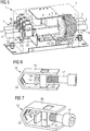
- Figure 1 shows a cross-sectional view of a line filter 1 which is installed onto a system cable 2.
- Figure 2 shows a perspective view of the line filter 1 installed onto the system cable 2.
- the line filter 1 is a kind of electronic filter that is placed between an electronic device (not shown) and a line (not shown) external to it, to attenuate conducted radio frequencies (RFI), also known as electromagnetic interference (EMI) between the external line and the electronic device or between electronic devices within a system.
- RFID conducted radio frequencies
- EMI electromagnetic interference
- the line filter 1 is provided by its manufacturer without the system cable 2. At the time of installation a suitable system cable 2 is provided by an installer. Then, the line filter 1 is installed onto the system cable 2 by an installer when the line filter 1 is placed between the electronic device and the line external to it or between electronic devices within a system.
- the system cable 2 comprises an insulation which covers a conductive internal material, e.g. copper.
- the line filter 1 comprises a housing 3.
- the housing 3 consists on a plastic material.
- the further parts of the line filter 1 are arranged inside the housing 3.
- the housing 3 is mountable on a system cabinet (not shown).
- the line filter 1 is a low pass filter.
- the line filter 1 comprises magnetic components 4 configured as in-line inductors and shunt components 5, e.g. shunt capacitors.
- the line filter 1 is configured such that the magnetic components 4 and the shunt components 5 form a LC-low pass filter when connected to the system cable 2.
- the line filter 1 defines a cable path 6 which runs through the line filter 1.
- the cable path 6 enters into the line filter 1 on a load side 7 and exits the line filter 1 on the line side 8.
- the line filter 1 is free from an internal main cable to which the system cable 2 would otherwise have to be electronically connected, e.g. by field wiring terminal.
- the line filter 1 comprises an aperture 9a at the load side 7 which is configured to allow entering the system cable 2 into the line filter 1 through the aperture 9a at the load side 7. Further, the line filter 1 comprises an aperture 10 at the line side 8 which is configured to allow exiting the system cable 2 from the line filter 1 through the aperture 10 at the line side 8.
- the system cable 2 comprises three phases 11, 12, 13.
- the line filter 1 comprises three apertures 9a, 9b, 9c arranged at the load side of the line filter.
- the line filter 1 comprises only one aperture 10 arranged at the line side 8 of the line filter 1.
- the cable path 6 defined through the line filter 1 connects each of the three apertures 9a, 9b, 9c on the load side 7 with the one aperture 10 on the line side 8.
- One phase 11, 12, 13 of the system cable 2 is entered into each of the apertures 9a, 9b, 9c on the load side 7 of the line filter 1. Further, all of the phases 9a, 9b, 9c of the system cable 2 exit the line filter 1 through the one aperture 10 on the line side 8.
- the line filter 1 comprises a guiding element 14 which is configured to help guide the system cable 2 along the cable path 6 during the placement of the system cable 2 along the cable path 6.
- the guiding element 14 is shaped as a single flat tube wherein multiple phases 11, 12, 13 of the system cable 2 are guided in the same flat tube.
- the guiding element 14 comprises a plastic material.
- the system cable 2 can be placed along the cable path 6 by being pushed into the line filter 1 from the load side 7.
- the guiding element 14 is configured such that the system cable 2 slides along the guiding element 14 and is, thereby, guided along the cable path 6 through the line filter 1. Once the line filter 1 has been installed onto the system cable 2, the guiding element 14 holds the system cable 2 in its position along the cable path 6.
- the line filter 1 comprises two magnetic components 4. In alternative designs, the line filter 1 can comprise one or more magnetic components.
- Each of the magnetic components 4 is a ring-shaped inductor core.
- the magnetic components 4 are inductors which are configured to be in-line connected to the system cable by a magnetic coupling.
- Each of the magnetic components 4 defines an opening 15 wherein the cable path 6 passes through the openings 15.
- the magnetic components 4 may be of any suitable shape which provides an opening 15.
- the phases 11, 12, 13 of system cable 2 may pass through separate magnetic components 4, i.e. one phase cable 11, 12, 13 per magnetic component 4.
- the line filter 1 further comprises at least one shunt component 5, e.g. a shunt capacitor.
- the line filter 1 further comprises an insulation displacement connector (IDC) 16.
- the IDC 16 is arranged in the vicinity of the load side 7 of the line filter 1.
- the IDC 16 comprises a screw 17 and a conductive pin 18.
- the conductive pin 18 is arranged at the end of the screw 17 which faces towards the system cable 2.
- the screw 17 and the pin 18 are formed by a single element.
- the screw 17 is a metal screw.
- the IDC 16 can be placed in any suitable location within the line filter 1.
- a platform 19 is arranged close to the end of the screw 17 which faces the system cable 2.
- the IDC 16 further comprises a cage 20.
- the platform 19 is configured to compress the system cable 2.
- the system cable 2 is mechanically fixed, e.g. clamped between the platform 19 and the cage 20, when the screw 17 is tightened.
- the cage 20 consists of a metal block 23 with thread to accept the screw 17 and a metal strap 24 that passes around the system cable 2.
- the conductive pin 18 pierces through the insulation of the system cable 2, thereby establishing a galvanic connection to the system cable 2.
- the insulation of the system cable is displaced when the conductive pin 18 pierces into the system cable 2.
- the pin 18 is pressed into the conductor of system cable 2 to provide a good galvanic connection to the conductive internal material of the system cable 2.
- the IDC 16 comprises a low current connection point (not shown) which is galvanically connected to the shunt components 5.
- the IDC 16 provides a galvanic connection of the system cable 2 to the shunt components 5.
- the IDC 16 comprises a small solder or crimp lug (not shown) configured to make a wire connection to at least one shunt component 5.
- the IDC 16 is configured to provide a voltage tap into the system cable 2. Accordingly, the same voltage as in the system cable 2 is also applied to the shunt component 5 when the galvanic connection is established. Further, the galvanic connection is configured to only draw a small shunt current through the conductive pin 18 from the system cable 2.
- the shunt current may be an order of magnitude, or more, smaller than the power current flowing through the system cable 2.
- the shunt current may be in the range of 0.1 A to 10 A.
- the IDC 16 comprises a plastic housing 21 which provides an insulation of the IDC 16.
- the IDC 16 is configured to provide a gas-tight seal of the system cable 2.
- the gas-tight seal is formed by the pressure of the platform 19 and cage 20 on the insulation of the system cable 2 and by the pressure applied by the displaced insulation of the system cable 2 on the conductive pin 18.
- the depth by which the pin 18 is designed to enter into the system cable 2 can be adjusted to provide different conductivity characteristics of the galvanic connections. Pin 18 may protrude into the conductor of system cable 2 by a fraction of a millimetre or several millimetres.
- the system cable 2 comprises three phases 11, 12, 13.
- the line filter 1 comprises three IDCs 16.
- Each of the IDCs 16 is assigned to one phase 11, 12, 13 of the system cable 2.
- each of the IDCs 16 is configured to galvanically connect one of the phases 11, 12, 13 of the system cable 2 to the shunt components 5.
- system cable 2 may comprise other numbers of phases.
- line filter 1 comprises one IDC 16 and one aperture 9a on the load side 7 per phase of the system cable 2.
- each IDC 16 may be connected to one phase of the system cable 2. Thereby, multiple stages of shunt components can be connected to system cable 2.
- each IDC 16 may comprise more than one conductive pin 18 which is configured to pierce into the system cable 2 when the screw 17 of the respective IDC 16 is tightened. This design also allows to draw a higher shunt current from the system cable 2 through the IDC 16.
- Figures 3 and 4 show details of the line filter 1.
- neither the housing 3 of the line filter 1 nor the shunt components 5 are shown in Figures 3 and 4 to improve comprehensibility.
- IDC connectors 16, cable guide 14 and magnetic components 4 are all shown.
- Figure 5 shows a perspective view of another alternative design of the line filter 1.
- the housing 3 is shown as partially see-through to improve comprehensibility.
- the design shown in Figure 5 differs from the previously described design in the design of the guiding element 14.
- the guiding element 14 comprises multiple separate tubes 22 wherein a tube 22 is provided for each of the phases 11, 12, 13 of the system cable 2.
- Figure 6 shows a perspective view of the above discussed IDC 16.
- FIG. 7 shows an alternative design of the IDC 16.
- the conductive pin 18 is arranged at the side of the cage 20 which is opposite to the screw 17.
- the basic functionality of the IDC 16 is not changed.
- the screw 17 is tightened, the system cable 2 is thereby compressed between the platform 19 and the cage 20 and the conductive pin 18 is forced to pierce into the system cable 2 at the same time.
- the IDC 16 comprises two conductive pins 18.
- a first conductive pin 18 is arranged on the end of the screw 17 which faces towards the system cable 2 as also shown in the embodiment of Figure 6 .
- a second conductive pin 18 is arranged at the side of the cage 20 which is opposite to the screw 17 as also shown in the embodiment of Figure 7 .
Landscapes
- Engineering & Computer Science (AREA)
- Power Engineering (AREA)
- Details Of Connecting Devices For Male And Female Coupling (AREA)
- Shielding Devices Or Components To Electric Or Magnetic Fields (AREA)
- Filters And Equalizers (AREA)
- Connections By Means Of Piercing Elements, Nuts, Or Screws (AREA)
Abstract
Description
- The present invention concerns a line filter and a method of installing the line filter onto a system cable. A line filter is a kind of electronic filter that is placed between an electronic device and an external line, or placed in any line interconnecting electronic devices within a system. A line filter is usually used to attenuate conducted radio frequencies (RFI), also known as electromagnetic interference (EMI) between the external line and the electronic device, or between electronic devices within a system.
- The installation of line filters to system cables requires a high level of expertise and is time-consuming. The quality of the connection is vital to ensure adequate conduction of the system current to avoid overheating of the termination. Usually, the line filters comprise a field wiring power terminal at the line side and another field wiring power terminal at the load side. The terminals are configured to be connected with a system cable input and a system cable output. In a three-wire-system, for example, this requires six system cable terminations each capable of carrying the full system current. For each termination the system cable must be prepared with the correct length of insulation removal, the wire end finished with a suitable sleeve and the cable fastened to the terminal with the correct torque. Periodically this torque must be re-checked.
- It is an object of the present invention to provide an improved line filter, e.g. which facilitates the installation. Another object of the present invention is to provide an improved method of installing a line filter onto a system cable.
- The object is solved by the line filter according to
claim 1. The further object is solved by the method according to the second independent claim. - A line filter is provided which is configured to be installed onto a system cable, wherein the line filter comprises a magnetic component, the line filter defines a cable path through the line filter, the line filter is configured to allow placement of the system cable along the cable path at the time of an installation, thereby providing a magnetic coupling of the system cable to the magnetic component, and wherein the line filter comprises an insulation displacement connector and a shunt component wherein the insulation displacement connector is configured to be tightened at the time of the installation, thereby providing a galvanic connection of the system cable to the shunt component.
- In this context, the term "at the time of an installation" may refer to the installation of the line filter to a system cable of an external electronic device. The time of the installation is not a time during the manufacturing of the line filter. The system cable is not an intrinsic part of the line filter. The line filter is installed onto the system cable at a point in time after the manufacturing of the line filter, and by a person different from the manufacturer, in particular e.g. by an installer or user of the electronic device.
- The line filter may be a low pass filter. The line filter may be configured to attenuate radio frequency interference, also known as electromagnetic interference (EMI). The line filter may be configured to attenuate a leakage current. The line filter may be configured to be connected between a power grid and an electrical load device or between electrical devices within a system, i.e. between a motor drive and motor. The line filter may provide electromagnetic compatibility (EMC) between devices.
- The line filter may comprise a means for eliminating earth leakage current from the system cable in the frequency range 150 Hz to 150 kHz. Alternatively, the line may comprise series inductive and shunt capacitive components in a ladder network to provide attenuation of radio frequency interference in the frequency range 150 kHz to 30 MHz.
- The magnetic component may be an inductor core.
- The cable path may be a predefined path which extends through the line filter. In particular, the cable path may connect a line side of the line filter to a load side of the line filter.
- In this context the term "placement of the system cable along the cable path" may be understood as an operation carried out by a user of the line filter or by an installer of the line filter. In this operation, the system cable may be placed manually along the cable path. In one embodiment, the system cable may be placed along the cable path by pushing the system cable through the line filter. However, alternative embodiments for the placement the cable along the cable path are also possible.
- The insulation displacement connector (IDC) is configured to provide a galvanic connection of the system cable to the shunt component. In particular, the IDC is configured to provide a voltage tap into the system cable which allows a small shunt current to be drawn from the system cable to the shunt component. Thereby, the same voltage may apply in the system cable and at the shunt component.
- The shunt component may comprise one or more shunt capacitors. The shunt component may be connected between the system cable and a grounding terminal, or between phases of the system cables. The line filter may comprise multiple shunt components which are connected in a ladder topology.
- As the line filter is configured to be magnetically coupled and galvanically connected to the system cable at the time of an installation onto the system cable, the line filter is free from an internal main power conductor connecting a line terminal and a load terminal. Instead, the system cable which is placed along the cable path at the time of installation directly connects with the magnetic components and the IDC. Thereby, the provision of field wiring terminals on the line filter is completely unnecessary and this results in saving on their inherent cost and bulk. This facilitates the field wiring for installation of the line filter and the time-consuming preparation of the system cabling for termination. Accordingly, the operation of installing the line filter onto a system cable is significantly facilitated.
- In one embodiment, the line filter comprises an aperture which is configured to allow placement of the system cable along the cable path by pushing the system cable through the aperture at the time of installation. Pushing the system cable through an aperture to enter into the line filter and providing another aperture through which the system cable can exit the line filter is a particularly easy way of installing the line filter onto the system cable. This allows a very fast installation and improves the user safety as installation errors, such as poor high current connections, are prevented.
- The IDC may comprise a screw and at least one conductive pin which is configured to pierce into the system cable when the screw is tightened. The IDC may comprise exactly one conductive pin. Alternatively, the IDC may comprise multiple conductive pins.
- In particular, the conductive pin may be configured to displace the insulation of the system cable. Accordingly, it is possible to de-install the line filter from the system cable by untightening the screw wherein the pin can be withdrawn from the system cable and the insulation sustains only minor damage.
- The pin may either be arranged to the end of the screw which is configured to face towards the system cable or the pin may be arranged such that it is on the side of the system cable which is opposite to the screw when the line filter installed onto the system cable.
- The conductive pin may be configured to pierce the system cable insulation and to protrude into the system cable a depth in the range of a fraction of a millimetre to several millimetres. In particular, the depth may be in the range of 0.01 mm to 20 mm. The system cable may comprise an inner conductor which is covered by an insulation. The conductive pin may be configured to pierce through the insulation and enter into the inner conductor.
- The depth by which the pin is designed to enter into the system cable can be adjusted to provide different conductivity characteristics for the galvanic connection of the IDC.
- The magnetic component may be ring-shaped and comprise an opening. The cable path may pass through the opening of the magnetic component. The magnetic component may be configured to reinforce a magnetic flux which is created by a current flowing through the system cable passing through the opening of the magnetic component. Thereby, the magnetic coupling between said two elements may be increased.
- The line filter may be free from an internal conductor winding. Accordingly, the cable may follow a direct path through the line filter. Thus, the cable path may be configured such that the system cable may be guided through the line filter in an almost straight line. This facilitates the placement of the system cable along the cable path by pushing. In particular, minimal deformation or twists of the system cable may be required while pushing the system cable along the straight line.
- The IDC may be configured to draw a shunt current from the system cable through the galvanic connection of the system cable to the shunt component wherein the shunt current is lower than a power current flowing through the system cable. In particular, the shunt current may be orders of magnitude lower than a current flowing through the system cable. The line filter shunt components may be designed to draw a relatively low current compared with a power current flowing through the system cable. Accordingly, the power current can be very high and will sustain no attenuation whereas radio frequency interference shunt current is removed from the system cable.
- The shunt current may in the range of 0.1 A to 10 A. At the same time, the current flowing through the system cable may be up to 1000 A. In particular, the current in the system cable may be in the range of 10 A to 1000 A. A voltage of up to 600 V may be present in the system cable. The line filter may be designed to provide attenuation in the
frequency range 1 kHz to 30 MHz. - The line filter may comprise multiple IDCs wherein each of the IDCs is configured to be tightened at the time of the installation, thereby providing galvanic connections of the system cable to the shunt component. In particular, the line filter may be configured to be installed onto a system cable which comprises one or more phases. The line filter may be configured such that all phases of the system cable are magnetically coupled to the same magnetic component when the system cable is placed along the cable path, or individual phases may couple to separate magnetic components. Further, the line filter may be configured to galvanically connect each phase of the system cable to at least one insulation displacement connector. This design allows to galvanically connect the different phases of the system cable individually. For example, the respective IDCs may be designed differently.
- Moreover, the line filter may comprise multiple IDCs which are configured to be connected to the same phase of the system cable. This may allow drawing stronger shunt current, or may allow the connection of multiple stages of shunt component.
- The line filter may further comprise a guiding element which is configured to mechanically guide the system cable along the cable path during the placement of the system cable along the cable path and which is configured to hold the system cable in the cable path once the system cable is placed along the cable path. The guiding element may be a plastic component.
- The line filter may be a low pass filter.
- The IDC may be configured to be connected to the system cable in a gas-tight connection.
- The IDC may be configured to provide a strain-relief when connected to the system cable.
- The IDC may be configured to provide a spring action which will maintain a constant clamping force over time.
- The line filter may be configured to be deinstalled from the system cable. In particular, the line filter may be deinstalled from the system cable by opening the IDC and by removing the system cable from the cable path, e.g. by pulling the system cable out of the line filter. The line filter may be configured such that during the deinstallation from the system cable, the system cable sustains minimal damage where the insulation is pierced but remains intact. The de-installation can be carried out by qualified user or installer.
- According to another aspect, the present invention relates to an assembly comprising the above-described line filter and the system cable.
- Further, the present invention relates to a method of installing a line filter onto a system cable, wherein the line filter comprises a magnetic component, an IDC and a shunt component. The method comprises the steps of:
- placing the system cable along a cable path defined through the line filter, thereby providing a magnetic coupling of the system cable to the magnetic component, and
- tightening the insulation displacement connector around the system cable, thereby providing a galvanic connection of the system cable to the shunt component.
- The line filter used in the method may be identical to the above-described line filter such that every functional and structural feature disclosed with respect to the line filter may also be applied with respect to the method.
- In the following, the invention is described in further detail with respect to the drawings.
-
Figure 1 shows a cross-sectional view of a line filter which is installed onto a system cable; -
Figure 2 shows a perspective view of the line filter installed onto the system cable; -
Figures 3 and 4 show details of the magnetic components, cable guide and IDC connectors in a perspective view; -
Figure 5 shows a perspective view of an alternative design of the line filter, showing IDC connectors, magnetic components, shunt components and cable guides; and -
Figure 6 shows a perspective view of an insulation displacement connector. -
Figure 7 shows a perspective view of an alternative insulation displacement connector. -
Figure 1 shows a cross-sectional view of aline filter 1 which is installed onto asystem cable 2.Figure 2 shows a perspective view of theline filter 1 installed onto thesystem cable 2. - The
line filter 1 is a kind of electronic filter that is placed between an electronic device (not shown) and a line (not shown) external to it, to attenuate conducted radio frequencies (RFI), also known as electromagnetic interference (EMI) between the external line and the electronic device or between electronic devices within a system. - The
line filter 1 is provided by its manufacturer without thesystem cable 2. At the time of installation asuitable system cable 2 is provided by an installer. Then, theline filter 1 is installed onto thesystem cable 2 by an installer when theline filter 1 is placed between the electronic device and the line external to it or between electronic devices within a system. Thesystem cable 2 comprises an insulation which covers a conductive internal material, e.g. copper. - The
line filter 1 comprises ahousing 3. Thehousing 3 consists on a plastic material. The further parts of theline filter 1 are arranged inside thehousing 3. Thehousing 3 is mountable on a system cabinet (not shown). - The
line filter 1 is a low pass filter. Theline filter 1 comprisesmagnetic components 4 configured as in-line inductors andshunt components 5, e.g. shunt capacitors. Theline filter 1 is configured such that themagnetic components 4 and theshunt components 5 form a LC-low pass filter when connected to thesystem cable 2. - The
line filter 1 defines acable path 6 which runs through theline filter 1. In particular, thecable path 6 enters into theline filter 1 on aload side 7 and exits theline filter 1 on theline side 8. As theline filter 1 defines thecable path 6 along which thesystem cable 2 can be placed, theline filter 1 is free from an internal main cable to which thesystem cable 2 would otherwise have to be electronically connected, e.g. by field wiring terminal. - The
line filter 1 comprises anaperture 9a at theload side 7 which is configured to allow entering thesystem cable 2 into theline filter 1 through theaperture 9a at theload side 7. Further, theline filter 1 comprises anaperture 10 at theline side 8 which is configured to allow exiting thesystem cable 2 from theline filter 1 through theaperture 10 at theline side 8. - In the embodiment shown in
Figures 1 and 2 , thesystem cable 2 comprises threephases line filter 1 comprises threeapertures line filter 1 comprises only oneaperture 10 arranged at theline side 8 of theline filter 1. Thecable path 6 defined through theline filter 1 connects each of the threeapertures load side 7 with the oneaperture 10 on theline side 8. Onephase system cable 2 is entered into each of theapertures load side 7 of theline filter 1. Further, all of thephases system cable 2 exit theline filter 1 through the oneaperture 10 on theline side 8. - Further, the
line filter 1 comprises a guidingelement 14 which is configured to help guide thesystem cable 2 along thecable path 6 during the placement of thesystem cable 2 along thecable path 6. The guidingelement 14 is shaped as a single flat tube whereinmultiple phases system cable 2 are guided in the same flat tube. The guidingelement 14 comprises a plastic material. - In particular, the
system cable 2 can be placed along thecable path 6 by being pushed into theline filter 1 from theload side 7. In this case, the guidingelement 14 is configured such that thesystem cable 2 slides along the guidingelement 14 and is, thereby, guided along thecable path 6 through theline filter 1. Once theline filter 1 has been installed onto thesystem cable 2, the guidingelement 14 holds thesystem cable 2 in its position along thecable path 6. - In the embodiment shown in
Figures 1 and 2 , theline filter 1 comprises twomagnetic components 4. In alternative designs, theline filter 1 can comprise one or more magnetic components. - Each of the
magnetic components 4 is a ring-shaped inductor core. In particular, themagnetic components 4 are inductors which are configured to be in-line connected to the system cable by a magnetic coupling. Each of themagnetic components 4 defines anopening 15 wherein thecable path 6 passes through theopenings 15. Thus, when thesystem cable 2 is placed along thecable path 6, thesystem cable 2 runs through theopenings 15 of themagnetic components 4. In particular, all phases 11, 12, 13 of thesystem cable 2 run through thesame openings 15 in themagnetic components 4. In alternative designs, themagnetic components 4 may be of any suitable shape which provides anopening 15. In alternative designs, thephases system cable 2 may pass through separatemagnetic components 4, i.e. onephase cable magnetic component 4. - When the
system cable 2 is placed such that it passes through theopenings 15 extending through themagnetic components 4, a magnetic coupling between thesystem cable 2 and themagnetic components 4 is established. In particular, thesystem cable 2 forms a single turn coupling with themagnetic components 4. - The
line filter 1 further comprises at least oneshunt component 5, e.g. a shunt capacitor. - The
line filter 1 further comprises an insulation displacement connector (IDC) 16. TheIDC 16 is arranged in the vicinity of theload side 7 of theline filter 1. TheIDC 16 comprises ascrew 17 and aconductive pin 18. In the embodiment shown inFigure 6 , theconductive pin 18 is arranged at the end of thescrew 17 which faces towards thesystem cable 2. Thus, thescrew 17 and thepin 18 are formed by a single element. Thescrew 17 is a metal screw. In alternative designs, theIDC 16 can be placed in any suitable location within theline filter 1. - Further, a
platform 19 is arranged close to the end of thescrew 17 which faces thesystem cable 2. TheIDC 16 further comprises acage 20. When thescrew 17 is tightened, theplatform 19 is configured to compress thesystem cable 2. Thesystem cable 2 is mechanically fixed, e.g. clamped between theplatform 19 and thecage 20, when thescrew 17 is tightened. Thecage 20 consists of ametal block 23 with thread to accept thescrew 17 and ametal strap 24 that passes around thesystem cable 2. - Moreover, when the
screw 17 is tightened, theconductive pin 18 pierces through the insulation of thesystem cable 2, thereby establishing a galvanic connection to thesystem cable 2. In particular, the insulation of the system cable is displaced when theconductive pin 18 pierces into thesystem cable 2. As thesystem cable 2 is compressed between theplatform 19 and thecage 20, it is ensured that thepin 18 is pressed into the conductor ofsystem cable 2 to provide a good galvanic connection to the conductive internal material of thesystem cable 2. - Furthermore, the
IDC 16 comprises a low current connection point (not shown) which is galvanically connected to theshunt components 5. When thescrew 17 is tightened, theIDC 16 provides a galvanic connection of thesystem cable 2 to theshunt components 5. In particular, theIDC 16 comprises a small solder or crimp lug (not shown) configured to make a wire connection to at least oneshunt component 5. - The
IDC 16 is configured to provide a voltage tap into thesystem cable 2. Accordingly, the same voltage as in thesystem cable 2 is also applied to theshunt component 5 when the galvanic connection is established. Further, the galvanic connection is configured to only draw a small shunt current through theconductive pin 18 from thesystem cable 2. The shunt current may be an order of magnitude, or more, smaller than the power current flowing through thesystem cable 2. The shunt current may be in the range of 0.1 A to 10 A. - Moreover, the
IDC 16 comprises aplastic housing 21 which provides an insulation of theIDC 16. TheIDC 16 is configured to provide a gas-tight seal of thesystem cable 2. The gas-tight seal is formed by the pressure of theplatform 19 andcage 20 on the insulation of thesystem cable 2 and by the pressure applied by the displaced insulation of thesystem cable 2 on theconductive pin 18. - The depth by which the
pin 18 is designed to enter into thesystem cable 2 can be adjusted to provide different conductivity characteristics of the galvanic connections.Pin 18 may protrude into the conductor ofsystem cable 2 by a fraction of a millimetre or several millimetres. - The
system cable 2 comprises threephases line filter 1 comprises threeIDCs 16. Each of theIDCs 16 is assigned to onephase system cable 2. In particular, each of theIDCs 16 is configured to galvanically connect one of thephases system cable 2 to theshunt components 5. - In alternative designs, the
system cable 2 may comprise other numbers of phases. In this case, theline filter 1 comprises oneIDC 16 and oneaperture 9a on theload side 7 per phase of thesystem cable 2. - In alternative designs, more than one
IDC 16 may be connected to one phase of thesystem cable 2. Thereby, multiple stages of shunt components can be connected tosystem cable 2. Alternatively or additionally, eachIDC 16 may comprise more than oneconductive pin 18 which is configured to pierce into thesystem cable 2 when thescrew 17 of therespective IDC 16 is tightened. This design also allows to draw a higher shunt current from thesystem cable 2 through theIDC 16. -
Figures 3 and 4 show details of theline filter 1. In particular, neither thehousing 3 of theline filter 1 nor theshunt components 5 are shown inFigures 3 and 4 to improve comprehensibility. Inparticular IDC connectors 16,cable guide 14 andmagnetic components 4 are all shown. -
Figure 5 shows a perspective view of another alternative design of theline filter 1. InFigure 5 thehousing 3 is shown as partially see-through to improve comprehensibility. - The design shown in
Figure 5 differs from the previously described design in the design of the guidingelement 14. In the design shown inFigure 5 , the guidingelement 14 comprises multiple separate tubes 22 wherein a tube 22 is provided for each of thephases system cable 2. -
Figure 6 shows a perspective view of the above discussedIDC 16. -
Figure 7 shows an alternative design of theIDC 16. In theIDC 16 shown inFigure 7 , theconductive pin 18 is arranged at the side of thecage 20 which is opposite to thescrew 17. However, the basic functionality of theIDC 16 is not changed. When thescrew 17 is tightened, thesystem cable 2 is thereby compressed between theplatform 19 and thecage 20 and theconductive pin 18 is forced to pierce into thesystem cable 2 at the same time. - In another alternative design, the
IDC 16 comprises twoconductive pins 18. A firstconductive pin 18 is arranged on the end of thescrew 17 which faces towards thesystem cable 2 as also shown in the embodiment ofFigure 6 . A secondconductive pin 18 is arranged at the side of thecage 20 which is opposite to thescrew 17 as also shown in the embodiment ofFigure 7 . By providing twoconductive pins 18, a higher shunt current can be drawn from thesystem cable 2. No modification of other functions are required. -
- 1
- line filter
- 2
- system cable
- 3
- housing
- 4
- magnetic component
- 5
- shunt component
- 6
- cable path
- 7
- load side
- 8
- line side
- 9a, 9b, 9c
- aperture at the load side
- 10
- aperture at the line side
- 11, 12, 13
- phase of the system cable
- 14
- guiding element
- 15
- opening
- 16
- insulation displacement connector (IDC)
- 17
- screw
- 18
- conductive pin
- 19
- platform
- 20
- cage
- 21
- plastic housing of the IDC
- 22
- tube
- 23
- block
- 24
- strap
Claims (15)
- Line filter (1),
which is configured to be installed onto a system cable (2),
wherein the line filter (1) comprises a magnetic component (4),
wherein the line filter (1) defines a cable path (6) through the line filter (1),
wherein the line filter (1) is configured to allow a placement of the system cable (2) along the cable path (6) at the time of an installation, thereby providing a magnetic coupling of the system cable (2) to the magnetic component (4), and
wherein the line filter (1) comprises an insulation displacement connector (16) and a shunt component (5) wherein the insulation displacement connector (16) is configured to be tightened at the time of the installation, thereby providing a galvanic connection of the system cable (2) to the shunt component (5). - Line filter (1) according to claim 1,
wherein the line filter (1) comprises an aperture (9a, 9b, 9c, 10) which is configured to allow the placement of the system cable (2) along the cable path (6) by pushing the system cable (2) through the aperture (9a, 9b, 9c, 10) at the time of the installation. - Line filter (1) according to one of the preceding claims,
wherein the insulation displacement connector (16) comprises a screw (17) and at least one conductive pin (18) which is configured to pierce into the system cable (2) when the screw (17) is tightened. - Line filter (1) according to claim 3,
wherein the pin (18) is either arranged at the end of the screw (17) which is configured to face towards the system cable (2) or wherein the pin (18) is arranged such that it is on the side of the system cable (2) which is opposite to the screw (17) when the line filter (1) is installed onto the system cable (2). - Line filter (1) according to claim 3 or 4,
wherein the conductive pin (18) is configured to pierce into the system cable (2) and protrude into the system cable (2) with a depth in the range of a 0.01 mm to 20 mm. - Line filter (1) according to one of the preceding claims,
wherein the magnetic component (4) is ring-shaped and comprises an opening (15), and
wherein the cable path (6) passes through the opening (15) of the magnetic component (4). - Line filter (1) according to one of the preceding claims,
wherein the line filter (1) is free from internal conductor windings. - Line filter (1) according to one of the preceding claims,
wherein the insulation displacement connector (16) is configured to draw a shunt current from the system cable (2) through the galvanic connection of the system cable (2) to the shunt component (5), wherein the shunt current is lower than a current flowing through the system cable (2). - Line filter (1) according to claim 8,
wherein the shunt current is in the range of 0.1 A to 10 A. - Line filter (1) according to one of the preceding claims,
comprising multiple insulation displacement connectors (16) wherein each of the insulation displacement connectors (16) is configured to be tightened at the time of the installation, thereby providing galvanic connections of the system cable (2) to the shunt component (5). - Line filter (1) according to one of the preceding claims,
which is configured to be installed onto a system cable (2) which comprises at least one phase (11, 12, 13), wherein the line filter (1) is configured such that all phases (11, 12, 13) of the system cable (2) are magnetically connected to the magnetic component (4) when the system cable (2) is placed along the cable path (6), and
wherein the line filter (1) is configured to allow galvanically connecting each phase (11, 12, 13) of the system cable (2) to at least one insulation displacement connector (16). - Line filter (1) according to one of the preceding claims,
which comprises a guiding element (14) which is configured to mechanically guide the system cable (2) along the cable path (6) during the placement of the system cable (2) along the cable path (6) and which is configured to hold the system cable (2) in the cable path (6) once the system cable (2) is placed along the cable path (6). - Line filter (1) according to one of the preceding claims,
wherein the line filter (1) is configured to allow deinstallment of the line filter (1) from the system cable (2). - Assembly comprising a line filter (1) according to one of the preceding claims and a system cable (2).
- Method of installing a line filter (1) onto a system cable (2),
wherein the line filter (1) comprises a magnetic component (4), an insulation displacement connector (16) and a shunt component (5),
wherein the method comprises the steps of:- placing the system cable (2) along a cable path (6) defined through the line filter (1), thereby providing a magnetic coupling of the system cable (2) to the magnetic component (4), and- tightening the insulation displacement connector (16) around the system cable (2), thereby providing a galvanic connection of the system cable (2) to the shunt component (5).
Priority Applications (6)
| Application Number | Priority Date | Filing Date | Title |
|---|---|---|---|
| EP14192512.3A EP3018766A1 (en) | 2014-11-10 | 2014-11-10 | Line filter and method of installing a line filter onto a system cable |
| JP2017525048A JP6652564B2 (en) | 2014-11-10 | 2015-10-30 | How to install line filters on line filters and system cables |
| PCT/EP2015/075320 WO2016074955A1 (en) | 2014-11-10 | 2015-10-30 | Line filter and method of installing a line filter onto a system cable |
| US15/525,576 US10447224B2 (en) | 2014-11-10 | 2015-10-30 | Line filter and method of installing a line filter onto a system cable |
| CN201580061070.0A CN107112642B (en) | 2014-11-10 | 2015-10-30 | Line filter and method for mounting line filter on system cable |
| EP15793729.3A EP3218969B1 (en) | 2014-11-10 | 2015-10-30 | Line filter and method of installing a line filter onto a system cable |
Applications Claiming Priority (1)
| Application Number | Priority Date | Filing Date | Title |
|---|---|---|---|
| EP14192512.3A EP3018766A1 (en) | 2014-11-10 | 2014-11-10 | Line filter and method of installing a line filter onto a system cable |
Publications (1)
| Publication Number | Publication Date |
|---|---|
| EP3018766A1 true EP3018766A1 (en) | 2016-05-11 |
Family
ID=51870902
Family Applications (2)
| Application Number | Title | Priority Date | Filing Date |
|---|---|---|---|
| EP14192512.3A Ceased EP3018766A1 (en) | 2014-11-10 | 2014-11-10 | Line filter and method of installing a line filter onto a system cable |
| EP15793729.3A Active EP3218969B1 (en) | 2014-11-10 | 2015-10-30 | Line filter and method of installing a line filter onto a system cable |
Family Applications After (1)
| Application Number | Title | Priority Date | Filing Date |
|---|---|---|---|
| EP15793729.3A Active EP3218969B1 (en) | 2014-11-10 | 2015-10-30 | Line filter and method of installing a line filter onto a system cable |
Country Status (5)
| Country | Link |
|---|---|
| US (1) | US10447224B2 (en) |
| EP (2) | EP3018766A1 (en) |
| JP (1) | JP6652564B2 (en) |
| CN (1) | CN107112642B (en) |
| WO (1) | WO2016074955A1 (en) |
Families Citing this family (3)
| Publication number | Priority date | Publication date | Assignee | Title |
|---|---|---|---|---|
| DE102017113556C5 (en) * | 2017-06-20 | 2023-06-22 | Tdk Electronics Ag | filter component |
| US11431114B2 (en) * | 2020-02-14 | 2022-08-30 | Te Connectivity Solutions Gmbh | Enclosed connection systems for forming an enclosed connection between conductors, and methods including same |
| CN111933421A (en) * | 2020-09-15 | 2020-11-13 | 苏州汇川联合动力系统有限公司 | Support, filtering structure, machining method and motor controller |
Citations (8)
| Publication number | Priority date | Publication date | Assignee | Title |
|---|---|---|---|---|
| GB2153165A (en) * | 1984-01-20 | 1985-08-14 | Avx Corp | Connector assembly |
| US5461351A (en) * | 1994-06-06 | 1995-10-24 | Shusterman; Boris | Common-mode filtering attachment for power line connectors |
| US5630734A (en) * | 1995-12-13 | 1997-05-20 | General Motors Corporation | Connector with solderless filter |
| WO2000060701A1 (en) * | 1999-04-01 | 2000-10-12 | Nor.Web Dpl Limited | Coupling apparatus and method |
| GB2354118A (en) * | 1999-09-07 | 2001-03-14 | David Malcolm Goodwin | Channel shaped connector with insulation displacement contacts for connecting two conductors |
| US20050280484A1 (en) * | 2004-06-17 | 2005-12-22 | Fci Americas Technology, Inc. | Electrical filter assembly having IDC connection |
| WO2006076680A1 (en) * | 2005-01-14 | 2006-07-20 | Molex Incorporated | Modular filter connector |
| US20080100400A1 (en) * | 2006-10-31 | 2008-05-01 | Lucas Donald J | Filter package |
Family Cites Families (9)
| Publication number | Priority date | Publication date | Assignee | Title |
|---|---|---|---|---|
| JP2002305422A (en) * | 2001-04-06 | 2002-10-18 | Mitsubishi Electric Corp | Power line filter |
| JP2004147226A (en) * | 2002-10-25 | 2004-05-20 | Sumitomo Electric Ind Ltd | Communication filter |
| CN101073185A (en) | 2004-06-17 | 2007-11-14 | Fci公司 | Electrical filter components with IDC connection |
| US7104832B2 (en) * | 2004-08-05 | 2006-09-12 | 3M Innovative Properties Company | Modular electrical connector and method of using |
| JP4137895B2 (en) * | 2005-02-02 | 2008-08-20 | Tdk株式会社 | Noise absorber |
| CN101897109B (en) * | 2007-10-10 | 2014-12-31 | 沙夫纳Emv股份公司 | Emc filter |
| CN201877579U (en) | 2010-11-25 | 2011-06-22 | 单博雅 | Thimble type voltage obtaining device |
| JP5697238B2 (en) | 2010-12-13 | 2015-04-08 | 矢崎総業株式会社 | Wire harness |
| JP2014067600A (en) * | 2012-09-26 | 2014-04-17 | Denso Wave Inc | Wire connection device of programmable logic controller |
-
2014
- 2014-11-10 EP EP14192512.3A patent/EP3018766A1/en not_active Ceased
-
2015
- 2015-10-30 US US15/525,576 patent/US10447224B2/en active Active
- 2015-10-30 EP EP15793729.3A patent/EP3218969B1/en active Active
- 2015-10-30 CN CN201580061070.0A patent/CN107112642B/en active Active
- 2015-10-30 JP JP2017525048A patent/JP6652564B2/en not_active Expired - Fee Related
- 2015-10-30 WO PCT/EP2015/075320 patent/WO2016074955A1/en not_active Ceased
Patent Citations (8)
| Publication number | Priority date | Publication date | Assignee | Title |
|---|---|---|---|---|
| GB2153165A (en) * | 1984-01-20 | 1985-08-14 | Avx Corp | Connector assembly |
| US5461351A (en) * | 1994-06-06 | 1995-10-24 | Shusterman; Boris | Common-mode filtering attachment for power line connectors |
| US5630734A (en) * | 1995-12-13 | 1997-05-20 | General Motors Corporation | Connector with solderless filter |
| WO2000060701A1 (en) * | 1999-04-01 | 2000-10-12 | Nor.Web Dpl Limited | Coupling apparatus and method |
| GB2354118A (en) * | 1999-09-07 | 2001-03-14 | David Malcolm Goodwin | Channel shaped connector with insulation displacement contacts for connecting two conductors |
| US20050280484A1 (en) * | 2004-06-17 | 2005-12-22 | Fci Americas Technology, Inc. | Electrical filter assembly having IDC connection |
| WO2006076680A1 (en) * | 2005-01-14 | 2006-07-20 | Molex Incorporated | Modular filter connector |
| US20080100400A1 (en) * | 2006-10-31 | 2008-05-01 | Lucas Donald J | Filter package |
Also Published As
| Publication number | Publication date |
|---|---|
| CN107112642A (en) | 2017-08-29 |
| EP3218969B1 (en) | 2021-04-14 |
| JP6652564B2 (en) | 2020-02-26 |
| JP2018504796A (en) | 2018-02-15 |
| WO2016074955A1 (en) | 2016-05-19 |
| CN107112642B (en) | 2019-12-20 |
| US20170338787A1 (en) | 2017-11-23 |
| EP3218969A1 (en) | 2017-09-20 |
| US10447224B2 (en) | 2019-10-15 |
Similar Documents
| Publication | Publication Date | Title |
|---|---|---|
| EP2544314B1 (en) | Contact means for attaching an end of a cable | |
| DE102016209883B4 (en) | wiring harness | |
| CN108092026B (en) | Electrical plug connector for multi-core cables | |
| CN113396081A (en) | Terminal assembly for electric vehicle charger, charger and manufacturing method of terminal assembly and charger | |
| EP3683892A2 (en) | Electrical connector | |
| CN108092027B (en) | Electrical plug connectors for multi-core cables | |
| US10057987B2 (en) | Printed circuit board with side access termination pads | |
| US10447224B2 (en) | Line filter and method of installing a line filter onto a system cable | |
| CN106410543A (en) | Electrical distributor arrangement | |
| EP3014708B1 (en) | Icm optimization and standardization for automation | |
| EP1995851A1 (en) | Coil connecting structure, coil connecting method, set of conductors, and electric motor | |
| CN108092016B (en) | Electrical plug connector for multi-core cables | |
| CN107925392B (en) | Conductive circuit with noise filter | |
| US20210021076A1 (en) | Single Pair Ethernet Connector | |
| US9153912B2 (en) | Connector backshell for shielded conductors | |
| US5924877A (en) | Ground connector for rack-mount modules and methods of operation and manufacture therefor | |
| CN215525871U (en) | Shielding experiment cable system of electromagnetic radiation standard exceeding detachable combined filter capacitor | |
| EP1024558A2 (en) | Connecting device for high-voltage cable | |
| CN220556625U (en) | Cable taking and operating machine | |
| EP4210177B1 (en) | Dual connector with spring and insulation displacement connection (idc) terminals | |
| DE202019106867U1 (en) | Connection device for electrical contacting of an electrical device | |
| CN222826716U (en) | Flat shielded wire device | |
| CN212783965U (en) | Plug-in combined wire harness | |
| CN202026235U (en) | Mounting devices and circuit frames for frequency converters | |
| KR0144611B1 (en) | Focus unit withdrawal cable coupler for flyback transformers |
Legal Events
| Date | Code | Title | Description |
|---|---|---|---|
| PUAI | Public reference made under article 153(3) epc to a published international application that has entered the european phase |
Free format text: ORIGINAL CODE: 0009012 |
|
| AK | Designated contracting states |
Kind code of ref document: A1 Designated state(s): AL AT BE BG CH CY CZ DE DK EE ES FI FR GB GR HR HU IE IS IT LI LT LU LV MC MK MT NL NO PL PT RO RS SE SI SK SM TR |
|
| AX | Request for extension of the european patent |
Extension state: BA ME |
|
| 17P | Request for examination filed |
Effective date: 20161110 |
|
| RBV | Designated contracting states (corrected) |
Designated state(s): AL AT BE BG CH CY CZ DE DK EE ES FI FR GB GR HR HU IE IS IT LI LT LU LV MC MK MT NL NO PL PT RO RS SE SI SK SM TR |
|
| 17Q | First examination report despatched |
Effective date: 20170222 |
|
| RAP1 | Party data changed (applicant data changed or rights of an application transferred) |
Owner name: EPCOS AG |
|
| 18R | Application refused |
Effective date: 20171130 |