EP3018494A1 - Ctfm detection apparatus and underwater detection apparatus - Google Patents
Ctfm detection apparatus and underwater detection apparatus Download PDFInfo
- Publication number
- EP3018494A1 EP3018494A1 EP15193062.5A EP15193062A EP3018494A1 EP 3018494 A1 EP3018494 A1 EP 3018494A1 EP 15193062 A EP15193062 A EP 15193062A EP 3018494 A1 EP3018494 A1 EP 3018494A1
- Authority
- EP
- European Patent Office
- Prior art keywords
- detection apparatus
- transmission
- receiving element
- ctfm
- reception
- Prior art date
- Legal status (The legal status is an assumption and is not a legal conclusion. Google has not performed a legal analysis and makes no representation as to the accuracy of the status listed.)
- Withdrawn
Links
- 238000001514 detection method Methods 0.000 title claims abstract description 150
- 230000005540 biological transmission Effects 0.000 claims abstract description 84
- 230000007246 mechanism Effects 0.000 claims abstract description 16
- 230000001154 acute effect Effects 0.000 claims description 4
- 230000004048 modification Effects 0.000 description 33
- 238000012986 modification Methods 0.000 description 33
- 238000000034 method Methods 0.000 description 12
- 230000006870 function Effects 0.000 description 9
- 238000001228 spectrum Methods 0.000 description 7
- 241000251468 Actinopterygii Species 0.000 description 6
- 238000004088 simulation Methods 0.000 description 6
- 230000008569 process Effects 0.000 description 5
- 238000010408 sweeping Methods 0.000 description 5
- 238000010586 diagram Methods 0.000 description 4
- XLYOFNOQVPJJNP-UHFFFAOYSA-N water Substances O XLYOFNOQVPJJNP-UHFFFAOYSA-N 0.000 description 4
- 238000006243 chemical reaction Methods 0.000 description 3
- 230000000694 effects Effects 0.000 description 3
- 230000007480 spreading Effects 0.000 description 3
- 238000007796 conventional method Methods 0.000 description 1
- 230000006866 deterioration Effects 0.000 description 1
- 238000002592 echocardiography Methods 0.000 description 1
- 238000005516 engineering process Methods 0.000 description 1
- 239000000284 extract Substances 0.000 description 1
- 239000011435 rock Substances 0.000 description 1
- 230000035945 sensitivity Effects 0.000 description 1
- 238000004904 shortening Methods 0.000 description 1
Images



Classifications
-
- G—PHYSICS
- G01—MEASURING; TESTING
- G01S—RADIO DIRECTION-FINDING; RADIO NAVIGATION; DETERMINING DISTANCE OR VELOCITY BY USE OF RADIO WAVES; LOCATING OR PRESENCE-DETECTING BY USE OF THE REFLECTION OR RERADIATION OF RADIO WAVES; ANALOGOUS ARRANGEMENTS USING OTHER WAVES
- G01S15/00—Systems using the reflection or reradiation of acoustic waves, e.g. sonar systems
- G01S15/02—Systems using the reflection or reradiation of acoustic waves, e.g. sonar systems using reflection of acoustic waves
- G01S15/06—Systems determining the position data of a target
- G01S15/42—Simultaneous measurement of distance and other co-ordinates
-
- G—PHYSICS
- G01—MEASURING; TESTING
- G01S—RADIO DIRECTION-FINDING; RADIO NAVIGATION; DETERMINING DISTANCE OR VELOCITY BY USE OF RADIO WAVES; LOCATING OR PRESENCE-DETECTING BY USE OF THE REFLECTION OR RERADIATION OF RADIO WAVES; ANALOGOUS ARRANGEMENTS USING OTHER WAVES
- G01S15/00—Systems using the reflection or reradiation of acoustic waves, e.g. sonar systems
- G01S15/02—Systems using the reflection or reradiation of acoustic waves, e.g. sonar systems using reflection of acoustic waves
- G01S15/06—Systems determining the position data of a target
- G01S15/08—Systems for measuring distance only
- G01S15/32—Systems for measuring distance only using transmission of continuous waves, whether amplitude-, frequency-, or phase-modulated, or unmodulated
- G01S15/34—Systems for measuring distance only using transmission of continuous waves, whether amplitude-, frequency-, or phase-modulated, or unmodulated using transmission of continuous, frequency-modulated waves while heterodyning the received signal, or a signal derived therefrom, with a locally-generated signal related to the contemporaneously transmitted signal
-
- G—PHYSICS
- G01—MEASURING; TESTING
- G01S—RADIO DIRECTION-FINDING; RADIO NAVIGATION; DETERMINING DISTANCE OR VELOCITY BY USE OF RADIO WAVES; LOCATING OR PRESENCE-DETECTING BY USE OF THE REFLECTION OR RERADIATION OF RADIO WAVES; ANALOGOUS ARRANGEMENTS USING OTHER WAVES
- G01S15/00—Systems using the reflection or reradiation of acoustic waves, e.g. sonar systems
- G01S15/88—Sonar systems specially adapted for specific applications
- G01S15/89—Sonar systems specially adapted for specific applications for mapping or imaging
-
- G—PHYSICS
- G01—MEASURING; TESTING
- G01S—RADIO DIRECTION-FINDING; RADIO NAVIGATION; DETERMINING DISTANCE OR VELOCITY BY USE OF RADIO WAVES; LOCATING OR PRESENCE-DETECTING BY USE OF THE REFLECTION OR RERADIATION OF RADIO WAVES; ANALOGOUS ARRANGEMENTS USING OTHER WAVES
- G01S15/00—Systems using the reflection or reradiation of acoustic waves, e.g. sonar systems
- G01S15/88—Sonar systems specially adapted for specific applications
- G01S15/96—Sonar systems specially adapted for specific applications for locating fish
-
- G—PHYSICS
- G01—MEASURING; TESTING
- G01S—RADIO DIRECTION-FINDING; RADIO NAVIGATION; DETERMINING DISTANCE OR VELOCITY BY USE OF RADIO WAVES; LOCATING OR PRESENCE-DETECTING BY USE OF THE REFLECTION OR RERADIATION OF RADIO WAVES; ANALOGOUS ARRANGEMENTS USING OTHER WAVES
- G01S7/00—Details of systems according to groups G01S13/00, G01S15/00, G01S17/00
- G01S7/52—Details of systems according to groups G01S13/00, G01S15/00, G01S17/00 of systems according to group G01S15/00
- G01S7/521—Constructional features
-
- G—PHYSICS
- G10—MUSICAL INSTRUMENTS; ACOUSTICS
- G10K—SOUND-PRODUCING DEVICES; METHODS OR DEVICES FOR PROTECTING AGAINST, OR FOR DAMPING, NOISE OR OTHER ACOUSTIC WAVES IN GENERAL; ACOUSTICS NOT OTHERWISE PROVIDED FOR
- G10K11/00—Methods or devices for transmitting, conducting or directing sound in general; Methods or devices for protecting against, or for damping, noise or other acoustic waves in general
- G10K11/18—Methods or devices for transmitting, conducting or directing sound
- G10K11/26—Sound-focusing or directing, e.g. scanning
- G10K11/35—Sound-focusing or directing, e.g. scanning using mechanical steering of transducers or their beams
- G10K11/352—Sound-focusing or directing, e.g. scanning using mechanical steering of transducers or their beams by moving the transducer
-
- G—PHYSICS
- G01—MEASURING; TESTING
- G01S—RADIO DIRECTION-FINDING; RADIO NAVIGATION; DETERMINING DISTANCE OR VELOCITY BY USE OF RADIO WAVES; LOCATING OR PRESENCE-DETECTING BY USE OF THE REFLECTION OR RERADIATION OF RADIO WAVES; ANALOGOUS ARRANGEMENTS USING OTHER WAVES
- G01S15/00—Systems using the reflection or reradiation of acoustic waves, e.g. sonar systems
- G01S15/88—Sonar systems specially adapted for specific applications
- G01S15/89—Sonar systems specially adapted for specific applications for mapping or imaging
- G01S15/8906—Short-range imaging systems; Acoustic microscope systems using pulse-echo techniques
- G01S15/8909—Short-range imaging systems; Acoustic microscope systems using pulse-echo techniques using a static transducer configuration
- G01S15/8915—Short-range imaging systems; Acoustic microscope systems using pulse-echo techniques using a static transducer configuration using a transducer array
- G01S15/8918—Short-range imaging systems; Acoustic microscope systems using pulse-echo techniques using a static transducer configuration using a transducer array the array being linear
-
- G—PHYSICS
- G01—MEASURING; TESTING
- G01S—RADIO DIRECTION-FINDING; RADIO NAVIGATION; DETERMINING DISTANCE OR VELOCITY BY USE OF RADIO WAVES; LOCATING OR PRESENCE-DETECTING BY USE OF THE REFLECTION OR RERADIATION OF RADIO WAVES; ANALOGOUS ARRANGEMENTS USING OTHER WAVES
- G01S15/00—Systems using the reflection or reradiation of acoustic waves, e.g. sonar systems
- G01S15/88—Sonar systems specially adapted for specific applications
- G01S15/89—Sonar systems specially adapted for specific applications for mapping or imaging
- G01S15/8906—Short-range imaging systems; Acoustic microscope systems using pulse-echo techniques
- G01S15/8934—Short-range imaging systems; Acoustic microscope systems using pulse-echo techniques using a dynamic transducer configuration
- G01S15/8938—Short-range imaging systems; Acoustic microscope systems using pulse-echo techniques using a dynamic transducer configuration using transducers mounted for mechanical movement in two dimensions
- G01S15/894—Short-range imaging systems; Acoustic microscope systems using pulse-echo techniques using a dynamic transducer configuration using transducers mounted for mechanical movement in two dimensions by rotation about a single axis
-
- G—PHYSICS
- G01—MEASURING; TESTING
- G01S—RADIO DIRECTION-FINDING; RADIO NAVIGATION; DETERMINING DISTANCE OR VELOCITY BY USE OF RADIO WAVES; LOCATING OR PRESENCE-DETECTING BY USE OF THE REFLECTION OR RERADIATION OF RADIO WAVES; ANALOGOUS ARRANGEMENTS USING OTHER WAVES
- G01S15/00—Systems using the reflection or reradiation of acoustic waves, e.g. sonar systems
- G01S15/88—Sonar systems specially adapted for specific applications
- G01S15/89—Sonar systems specially adapted for specific applications for mapping or imaging
- G01S15/8906—Short-range imaging systems; Acoustic microscope systems using pulse-echo techniques
- G01S15/895—Short-range imaging systems; Acoustic microscope systems using pulse-echo techniques characterised by the transmitted frequency spectrum
- G01S15/8954—Short-range imaging systems; Acoustic microscope systems using pulse-echo techniques characterised by the transmitted frequency spectrum using a broad-band spectrum
Definitions
- This disclosure generally relates to a CTFM detection apparatus and an underwater detection apparatus, which detect a target object in 3-dimensional space.
- detection apparatuses include, for example, detection apparatuses disclosed in US2013/215719A1 and "CTFM Sonar SS330" by SUNWEST TECHNOLOGIES [online] [searched on August 29 in 2014] on the Internet (http://www.sunwest-tech.com/SS300%20Broch%20-%20REV%20G.pdf).
- a sonar detection apparatus
- a sonar which is capable of detecting 360° within the horizontal plane by rotating 180° two sonar elements arranged to transmit sonar signals to opposite directions from each other (or by rotating 360° a single sonar element).
- a sonar detection apparatus
- a transmitting element capable of generating a beam spreading into a fan-shape (i.e., fan-beam)
- a receiving element capable of generating a comparatively narrow beam (i.e., pencil beam).
- a scanning sonar is also generally known, which is capable of detecting target objects within a predetermined range in a comparatively short time period by performing, with a 2-dimensionally arranged array, a beamforming on echoes of transmission waves transmitted over all azimuths.
- the detection apparatus disclosed in US2013/215719A1 described above is a detection apparatus of a so-called pulse echo method type (i.e. non-continuous transmission of pulse), it comparatively takes time to detect target objects. Specifically, since a time period required to receive a reflected wave resulting from a pulse-shaped transmission wave transmitted to a predetermined azimuth accumulates at every azimuth, it comparatively takes time to detect over a predetermined range.
- the purpose of this disclosure relates to providing at low cost a CTFM detection apparatus, which is capable of detecting a target object in 3-dimensional space in a short time period.
- a CTFM detection apparatus capable of detecting a target object in 3-dimensional space in a short time period can be provided at low cost.
- the underwater detection apparatus 1 of this embodiment is a CTFM (Continuous Transmission Frequency Modulated)-type detection apparatus, and for example, it is attached to a bottom of a ship (e.g., a fishing boat) and used mainly for detecting target objects (e.g., a single fish or a school of fish).
- the underwater detection apparatus 1 is also used for detecting undulation of a water bottom, such as a rock reef, and a structural object, such as an artificial fish reef.
- a target object in 3-dimensional space can be detected.
- Fig. 1 is a block diagram illustrating a configuration of the underwater detection apparatus 1 of this embodiment.
- the underwater detection apparatus 1 includes a projector 2 (which may also be referred to as a transmitting part of a transducer), a sensor 3, a motor 4 (which may also be referred to as a motion mechanism), a transmission-and-reception device 5, a signal processor 10, and a display unit 8.
- the projector 2 transmits underwater ultrasonic wave as transmission wave, and is fixed to the bottom of the ship so that a transmitting surface 2a from which ultrasonic wave is transmitted is exposed to the water and faces vertically downward.
- the transmitting surface 2a is formed into a circular shape.
- the projector 2 of this embodiment is capable of transmitting a 3-dimensional transmission beam VB over a comparatively wide range (i.e., the volume beam).
- the transmission beam VB has, for example, a conical shape extending downward with the vertex at the projector 2 (in this embodiment, a right conical shape).
- the opening angle of the conical shape is about 120°. However, this disclosure is not limited as such, and the opening angle may be less than or greater than 120°. For example, the angle may be between 90° and 180°.
- a frequency modulated ultrasonic wave may be transmitted from projector 2.
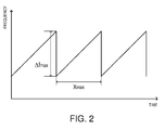
- the transmission wave is a chirp wave of which frequency gradually changes with time, and the projector 2 continuously transmits by repeatedly transmitting the chirp wave at a particular time cycle.
- Fig. 2 is a chart illustrating a relationship between time and frequency of the ultrasonic wave transmitted from the projector 2.
- X max indicates a sweeping time period and ⁇ f max indicates a sweeping bandwidth.
- the sensor 3 has a plurality of (in this embodiment, two) ultrasonic transducers 31a and 31b (which may also be referred to as receiving elements).
- the ultrasonic transducers 31a and 31b have receiving surfaces 32a and 32b where the ultrasonic wave is received, exposed to the water, respectively.
- Each of the ultrasonic transducers 31a and 31b receives a reflection wave resulting from a reflection of the ultrasonic wave transmitted by the projector 2, and converts it into an electric signal (e.g. a received signal).
- the illustration of the ultrasonic transducers 31a and 31b other than the receiving surfaces 32a and 32b is omitted in Fig. 1 .
- Fig. 3A is a bottom view schematically illustrating the two ultrasonic transducers 31a and 31b in Fig. 1 along with shapes of reception beams FB a and FB b formed by the respective ultrasonic transducers 31a and 31b
- Fig. 3B is a side view schematically illustrating the two ultrasonic transducers 31a and 31b in Fig. 1 along with the shapes of the reception beams FB a and FB b formed by the respective ultrasonic transducers 31a and 31b.
- Each of the receiving surfaces 32a and 32b is formed into an oblong rectangular shape in a plan view (when seen from below).
- the ultrasonic transducers 31a and 31b generate the reception beams FB a and FB b having a fan shape spreading along a surface perpendicular to the longitudinal direction of the receiving surfaces 32a and 32b, respectively.
- Each of the reception beams FB a and FB b is, for example, comparatively thin, as thin as about 6°. Note that, the thickness of each of the reception beams FB a and FB b corresponds to the width of the beam in the longitudinal direction of the receiving surfaces 32a and 32b.
- the receiving surfaces 32a and 32b are arranged to face downward. Specifically, the receiving surfaces 32a and 32b are arranged so that the surfaces 32a and 32b extend perpendicular to directions d a and d b , respectively, the directions d a and d b , inclining with respect to the vertically downward direction and oriented away from each other. Moreover, as illustrated in Fig. 3A , the receiving surfaces 32a and 32b are arranged so that short sides of the receiving surfaces 32a and 32b extend in the same direction as each other when seen in the up/down direction. Thus, the reception beams FB a and FB b are formed in the same vertical plane.
- a beam axis of the reception beam is an axis within the reception beam and extending in a direction where the highest reception sensitivity is obtained.
- the motor 4 sets the sensor 3 in motion. Specifically, the motor 4 repeatedly rotates the sensor 3 about a central axis extending vertically at a position between the receiving surfaces 32a and 32b.
- each of angles formed between the rotational axis of the sensor 3 and each of the beam axes of the reception beams FB a and FB b is not a right angle. In this embodiment, this angle is an acute angle.
- the sensor 3 rotates within the horizontal plane perpendicular to the vertical direction.
- the motor 4 repeatedly rotates the sensor 3 by a particular angle at a particular time interval.
- Fig. 4 is a view schematically illustrating a process of detecting the target object by the underwater detection apparatus 1, illustrated with the ship S on which the underwater detection apparatus 1 is mounted.
- the motor 4 rotates the sensor 3 to rotate the reception beams FB a and FB b formed by the ultrasonic transducers 31a and 31b, within the range of the transmission beam VB generated by the projector 2.
- the target object in 3-dimensional space below the ship space surrounded by the dashed lines in Fig. 4
- the target object in 3-dimensional space below the ship space surrounded by the dashed lines in Fig. 4
- the transmission-and-reception device 5 includes a transmitter 6 and a receiver 7.
- the transmitter 6 amplifies the frequency modulated transmission signal generated by the signal processor 10 to obtain a high-voltage transmission signal, and applies the high-voltage transmission signal to the projector 2.
- the receiver 7 amplifies the electric signal (received signal) outputted by the sensor 3, and A/D converts the amplified received signal. Then, the receiver 7 outputs the received signal converted into a digital signal, to the signal processor 10. Specifically, the receiver 7 has two receive circuits (not illustrated), and each receive circuit performs the processing described above on the received signal obtained by electroacoustically converting the reflected wave received by the corresponding ultrasonic transducer (31a or 31b), and outputs the processed received signal to the signal processor 10.
- the signal processor 10 generates the transmission signal (electric signal) and inputs it to the transmitter 6. Further, the signal processor 10 processes the received signal outputted by the receiver 7 to generate an image signal of the target object.
- the configuration of the signal processor 10 is described later in detail.
- the display unit 8 displays, on a display screen, an image corresponding to the image signal outputted by the signal processor 10.
- the display unit 8 displays an underwater state below the ship on a PPI (Plan Position Indication) display.
- PPI Plan Position Indication
- a user can estimate the underwater state below the ship (e.g., a single fish or a school of fish, undulation of the water bottom, whether the structural object, such as an artificial fish reef, exists, and a position thereof) by looking at the display screen.
- Fig. 5 is a block diagram illustrating a configuration of the signal processor 10.
- the signal processor 10 includes a transmission signal generator 10a, a transmission-and-reception processor 11, and a detection image generator 18 (which may also be referred to as a target object information generator or a target object information generating means).
- the transmission signal generator 10a generates the transmission signal (electric signal), basis of the transmission wave transmitted by the projector 2.
- the transmission signal generated by the transmission signal generator 10a is transmitted to the transmitter 6 and the transmission-and-reception processor 11.
- the transmission-and-reception processor 11 has two transmission-and-reception circuits 11a and 11b.
- Each of the transmission-and-reception circuits 11a and 11b receives the transmission signal generated by the transmission signal generator 10a and the received signal generated by the corresponding receive circuit (the received signal obtained by the corresponding one of the ultrasonic transducers 31a and 31b).
- the transmission-and-reception circuit 11a receives the received signal obtained by the ultrasonic transducer 31a
- the transmission-and-reception circuit 11b receives the received signal obtained by the ultrasonic transducer 31b.
- Each of the transmission-and-reception circuits 11a and 11b includes a first multiplier 12, a low-pass filter 13, a signal extractor 14, a window function memory 15, a second multiplier 16, and a frequency analyzer 17. Note that, each of the transmission-and-reception circuits 11a and 11b performs the same processing except that the received signal inputted to each transmission-and-reception circuit is different as each received signal is generated based on a different ultrasonic transducer.
- the first multiplier 12 generates a beat signal based on the transmission signal generated by the transmission signal generator 10a and the received signals obtained from the ultrasonic waves received by the ultrasonic transducers 31a and 31b. Specifically, the first multiplier 12 combines (e.g. mixes or multiplies) the transmission signal with the received signals described above to generate the beat signal.
- Fig. 6 is a chart illustrating one example of the beat signal generated by the first multiplier 12.
- the low-pass filter 13 removes an unrequired signal component (which is typically a high frequency component) from the beat signal generated by the first multiplier 12.
- the signal extractor 14 extracts a signal from within a section so as to process the signal in a post process. Specifically, the signal extractor 14 sets the section to be processed to be a reception gate section, and sets the beat signal within the reception gate section to be the extracted beat signal.
- Figs. 7A and 7B are views for describing the generation of the extracted beat signal, in which Fig. 7A illustrates a waveform of the beat signal outputted from the low-pass filter (i.e., a waveform before the extracted beat signal is extracted), and Fig. 7B illustrates a waveform of the extracted beat signal extracted from the beat signal in Fig. 7A .
- the window function memory 15 stores a particular window function. Further, the second multiplier 16 multiplies the extracted beat signal by the particular window function stored in the window function memory 15.
- the frequency analyzer 17 analyzes the output result from the second multiplier 16 (the extracted beat signal multiplied by the window function) and generates data indicating an amplitude and a phase (amplitude spectrum and phase spectrum; hereinafter, they may comprehensively be referred to as the complex spectrum) at each frequency.
- Examples of the analyzing method include a Discrete Fourier Transform (DFT) and a Fast Fourier Transform (FFT). Note that, by multiplying the extracted beat signal by the window function as described above, side lobes of the complex spectrum generated by the frequency analyzer 17 can be reduced.
- DFT Discrete Fourier Transform
- FFT Fast Fourier Transform
- the complex spectra corresponding to the ultrasonic transducers 31a and 31b are generated by the transmission-and-reception circuits 11a and 11b, respectively.
- the complex spectrum generated by each frequency analyzer 17 is outputted to the detection image generator 18.
- the detection image generator 18 converts a horizontal axis of the complex spectrum generated by each of the transmission-and-reception circuits 11a and 11b from a frequency into a distance (e.g. a distance from the ship) to generate echo data (complex amplitude data of the echo at each distance from the ship).
- a coefficient for the conversion from the frequency into the distance may be calculated to perform the conversion based on the sweeping bandwidth of the transmission signal, the sweeping time period of the transmission signal, and the underwater sound speed.
- the rotational speed of the motor 4 may need to be set so that a time period for rotating by the angle corresponding to the thickness of each of the reception beams FB a and FB b becomes longer than a time period corresponding to the reception gate section at the transmission-and-reception processor 11. In a case of shortening the detection time as much as possible, the rotational speed of the motor 4 may be set so that both of the time periods match with each other.
- a detection time for detecting a target object by the underwater detection apparatus 1 of this embodiment is compared, through simulation, with a detection time for detecting the target object by a known (general) underwater detection apparatus (underwater detection apparatus using mechanical scanning based on a pulse echo method).
- a detection time for the entire circumference can be compared. Therefore, hereinafter, the detection time of the underwater detection apparatus 1 of this embodiment is compared with that of by the known underwater detection apparatus, by comparing the time period to receive an echo at a single azimuth.
- the simulation is performed under a condition that the detection range is 25m, a range resolution is 0.19m, and a CTFM sweep bandwidth is 15 kHz.
- the detection time of the known underwater detection apparatus to receive an echo at a single azimuth was 33ms.
- this value was calculated based on a propagation time of an ultrasonic wave within the detection range. Specifically, the value is obtained by dividing a propagation distance of the ultrasonic wave (twice the detection range, 50m in the simulation described above) by the speed of the ultrasonic wave underwater (1,500m/s).
- the detection time of the underwater detection apparatus 1 was 9ms. Note that, this value was calculated based on the condition of the simulation described above. Specifically, when the detection range is 25m and the range resolution is 0.19m, the range resolution is 1/133 in ratio, and therefore, a value obtained by multiplying the CTFM sweeping bandwidth (15 kHz) by 1/113, 0.11 kHz, is a frequency resolution. A time period to achieve this frequency resolution can be calculated as 9ms by taking an inverse number of 0.11 kHz.
- the detection over the 3-dimensional space within the range of the 3-dimensional transmission beam VB is performed by setting the sensor 3 in motion.
- the detection over the 3-dimensional space can be performed.
- the receiving elements do not need to be arranged 2-dimensionally or 3-dimensionally as they are arranged in a conventional scanning sonar, and a number of receiving elements can be reduced. Therefore, the apparatus can be simplified.
- the underwater detection apparatus 1 detects the target object by using a CTFM method, compared to the case of adopting the pulse echo method, a time for detecting over a particular range can be shortened. More specifically, since the CTFM method is adopted, the underwater detection apparatus 1 can receive the ultrasonic wave at a single azimuth in a time period shorter than the time period for the round-trip propagation of the detection range by the ultrasonic pulse. Thus, the echo intensity at a single azimuth can be obtained in a comparatively short time period, and as a result, the time period for detecting the particular range can be shortened.
- the underwater detection apparatus 1 since the transmission beam VB has the 3-dimensional shape, a single transmission of the ultrasonic wave can cover the detection target area for the target object. In this manner, the projector 2 does not need to be moved in order to run through the entire detection area. Therefore, the apparatus can be simplified.
- a CTFM detection apparatus capable of detecting a target object in 3-dimensional space in a short time period can be provided at low cost.
- the 2-dimensional reception beams FB a and FB b are moved in the direction that intersects with the direction in which the 2-dimensional reception beams extend. Therefore, the 3-dimensional space can be scanned with the reception beams FB a and FB b . Furthermore, by forming the reception beams FB a and FB b into a 2-dimensional shape, the target object can be detected in a short time period, for example, compared to the case of scanning within the transmission beam with a pencil-shape reception beam.
- the 2-dimensional reception beams FB a and FB b are moved in the direction perpendicular to the direction in which the 2-dimensional reception beams extend. Therefore, the detection can be performed over a comparatively wide 3-dimensional space spreading from the underwater detection apparatus 1.
- the underwater detection apparatus 1 by moving the fan-shaped reception beams FB a and FB b , the detection can be performed over a comparatively wide 3-dimensional space below the ship.
- the receiving surfaces 32a and 32b are formed into the oblong rectangular shape. Therefore, the 2-dimensional reception beams FB a and FB b can suitably be formed.
- the projector 2 generates the conically shaped transmission beam VB (in this embodiment, right conical shape), and the sensor 3 scans the range of the transmission beam VB. Therefore, the detection can be performed over a wide range below the ship.
- the transmitting surface 2a is formed into the circular shape. Therefore, the 3-dimensional transmission beam VB can suitably be formed.
- a CTFM detection apparatus capable of detecting 3-dimensional space can be constructed with a comparatively simple configuration.
- each of the angles formed between the rotational axis of the sensor 3 and each of the beam axes of the reception beams FB a and FB b formed by the ultrasonic transducers 31a and 31b is one of zero degree, the acute angle, and the obtuse angle.
- the rotational axis does not intersect perpendicularly with the beam axes of the reception beams FB a and FB b . In this manner, the detection can be performed over a wide 3-dimensional space compared to the case where the rotational axis of the sensor is perpendicular to the beam axes.
- the receiving surfaces 32a and 32b are mutually oriented in the different directions d a and d b . Therefore, the detectable range at each angular position ( ⁇ in Fig. 4 ) can be extended.
- an underwater detection apparatus capable of detecting a target object in 3-dimensional space in a short time period can be provided at low cost.
- the underwater detection apparatus 1a of this modification includes a projector 2 having a similar configuration to the above embodiment.
- the projector 2 is fixed to a front side of the ship so that a transmitting surface thereof inclines forward of the ship with respect to the vertical direction.
- a transmission beam VB formed into a volume beam is generated to extend both forward of the ship and underwater.
- the transmission beam VB is of a conical shape so that it covers 0° to 45° when the horizontal direction is 0° and the vertically downward direction is 90°, and also covers a range from 45° on the starboard side to 45° on the port side.
- the underwater detection apparatus 1a of this modification includes a sensor 3 having a similar configuration to the above embodiment.
- Two ultrasonic transducers 31 a and 31b are arranged in the left-and-right directions of the ship.
- the sensor 3 similar to the case of the projector 2, is fixed to the front side of the ship so that a receiving surface thereof inclines forward of the ship with respect to the vertical direction.
- reception beams FB a and FB b are formed to extend both forward of the ship and underwater.
- the reception beam FB a of this modification is formed into a 2-dimensional shape in which the thickness in the up-and-down directions is comparatively thin, as thin as about 6°, and covers, when the forward direction is 0°, a range from 45° to 0° on the starboard side.
- the reception beam FB b is, for example, formed into a 2-dimensional shape in which the thickness in the up-and-down directions is comparatively thin, as thin as about 6°, and covers, when the forward direction is 0°, a range from 0° to 45° on the port side.
- the sensor 3 of this modification is inclined upward or downward by the motor 4 so as to vertically swing back and forth.
- the reception beams FB a and FB b can be vertically swung back and forth. Therefore, the detection can be performed 3-dimensionally over the forward area of the ship.
- a CTFM detection apparatus capable of detecting a target object in 3-dimensional space in a short time period can be provided at low cost.
- a CTFM detection apparatus capable of suitably detecting over a detection area extending in a particular direction (e.g. forward of the ship) can be constructed with a comparatively simple configuration.
- the direction of arrangement of the two ultrasonic transducers 31a and 31b may be in the front-and-rear directions (bow and stern directions) of the ship, and the moving direction of the reception beams FB a and FB b may be in the left-and-right directions.
- the transmission beam VB generated by the underwater detection apparatus 1b of this modification is generated into a volume beam shape wider (longer in the thickness direction) compared to the reception beam FB (specifically, elliptical conical shape).
- the volume beam VB with such a shape can be generated, for example, by forming the transmitting surface into an oblong rectangular shape.
- the aspect ratio of the transmitting surface is closer to 1 compared to the aspect ratio of the receiving surface of the receiving element.
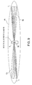
- the transmission beam VB is rotated by the motor in the direction indicated by the arrows in Fig. 9 , at the same rotational speed as the reception beam FB.
- the width (the length in the thickness direction) of the transmission beam VB can be determined based on a ratio of a time period of a reception gate section set by the underwater detection apparatus 1b of this modification with respect to a time period for the round trip propagation of the detection range by the ultrasonic pulse. For example, if this ratio is 1/3, by setting the transmission beam VB to be wider (longer in the thickness direction) than the range corresponding to three steps of rotation of the reception beam FB (see Fig. 9 ), even when the sensor is rotated without waiting for a return of the reflection wave at a particular rotational angle, the reflection wave can be received at the rotated angle. Therefore also in this modification, similar to the above embodiment, a CTFM detection apparatus capable of detecting a target object in 3-dimensional space in a short time period can be provided at low cost.
- the ultrasonic wave transmitted from the projector generating the transmission beam VB is not transmitted to all azimuths, and the transmission wave is transmitted only to the azimuth where the reception of the echo by the sensor is performed.
- the transmission wave can be transmitted with concentrated energy to a particular direction. Therefore, an electric power for transmitting the transmission wave can be reduced.
- a CTFM detection apparatus effective in saving energy can be provided.
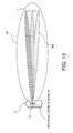
- the transmission beam VB is rotated by the motor in the direction indicated by the arrow in Fig. 10 , at the same rotational speed as the reception beam FB.
- the underwater detection apparatus 1c including only one receiving element, effects similar to the case of the underwater detection apparatus 1b in Fig. 9 can be obtained.
Landscapes
- Engineering & Computer Science (AREA)
- Radar, Positioning & Navigation (AREA)
- Remote Sensing (AREA)
- Physics & Mathematics (AREA)
- Computer Networks & Wireless Communication (AREA)
- General Physics & Mathematics (AREA)
- Acoustics & Sound (AREA)
- Multimedia (AREA)
- Measurement Of Velocity Or Position Using Acoustic Or Ultrasonic Waves (AREA)
Abstract
Description
- This disclosure generally relates to a CTFM detection apparatus and an underwater detection apparatus, which detect a target object in 3-dimensional space.
- Conventionally-known detection apparatuses include, for example, detection apparatuses disclosed in
US2013/215719A1 and "CTFM Sonar SS330" by SUNWEST TECHNOLOGIES [online] [searched on August 29 in 2014] on the Internet (http://www.sunwest-tech.com/SS300%20Broch%20-%20REV%20G.pdf). - In Paragraph [0069], Fig. 19, etc., of
US2013/215719A1 , a sonar (detection apparatus) is disclosed, which is capable of detecting 360° within the horizontal plane by rotating 180° two sonar elements arranged to transmit sonar signals to opposite directions from each other (or by rotating 360° a single sonar element). - Further, in "CTFM Sonar SS330," a sonar (detection apparatus) is disclosed, which includes a transmitting element capable of generating a beam spreading into a fan-shape (i.e., fan-beam), and a receiving element capable of generating a comparatively narrow beam (i.e., pencil beam). With this detection apparatus, target objects can be detected over a wide range by rotating with a motor the transmitting element and the receiving element.
- Furthermore, a scanning sonar is also generally known, which is capable of detecting target objects within a predetermined range in a comparatively short time period by performing, with a 2-dimensionally arranged array, a beamforming on echoes of transmission waves transmitted over all azimuths.
- However, since the detection apparatus disclosed in
US2013/215719A1 described above is a detection apparatus of a so-called pulse echo method type (i.e. non-continuous transmission of pulse), it comparatively takes time to detect target objects. Specifically, since a time period required to receive a reflected wave resulting from a pulse-shaped transmission wave transmitted to a predetermined azimuth accumulates at every azimuth, it comparatively takes time to detect over a predetermined range. - Further, with the detection apparatus disclosed in "CTFM Sonar SS330" described above, although target objects within a 2-dimensional range where a fan beam spreads can be detected, target objects in 3-dimensional space cannot be detected.
- With the scanning sonar described above, multiple elements are required to form the 2-dimensionally arranged array, which causes a cost increase.
- The purpose of this disclosure relates to providing at low cost a CTFM detection apparatus, which is capable of detecting a target object in 3-dimensional space in a short time period.
- (1) According to one aspect of this disclosure, a Continuous Transmission Frequency Modulated (CTFM) detection apparatus is provided. The CTFM detection apparatus includes a projector, a receiving element, a motion mechanism, and a target object information generator. The projector is configured to transmit a frequency modulated transmission wave and to generate a 3-dimensional transmission beam. The receiving element is configured to receive a reflected wave, the reflected wave comprising a reflection of the transmission wave. The motion mechanism is configured to set the receiving element in motion and to make a reception beam formed by the receiving element scan a 3-dimensional space within the transmission beam. The target object information generator is configured to generate information on target objects within the 3-dimensional space based at least in part on a beat signal generated based at least in part on the transmission wave transmitted by the projector and the reflected wave received by the receiving element.
- (2) The reception beam formed by the receiving element may be a 2-dimensional reception beam. The motion mechanism may set the receiving element in motion in a direction that intersects with a direction in which the 2-dimensional reception beam extends.
- (3) The motion mechanism may set the receiving element in motion in a direction perpendicular to the direction in which the 2-dimensional reception beam extends.
- (4) The reception beam formed by the receiving element may be of a fan shape.
- (5) A receiving surface on which the reflected wave is received by the receiving element may be of a rectangular shape.
- (6) The transmission beam generated by the projector may be of a conical shape. The reception beam, set in motion by the motion mechanism, may scan a conical range within the transmission beam.
- (7) A transmitting surface from which the transmission wave is transmitted by the projector may be of a circular shape.
- (8) The motion mechanism may rotate the receiving element.
- (9) An angle formed between a rotational axis of the receiving element and a beam axis of the reception beam may be an acute angle or an obtuse angle.
- (10) The motion mechanism may swing the receiving element back and forth.
- (11) The detection apparatus may include a plurality of the receiving elements. Receiving surfaces on which the reflected wave are received by each of the plurality of receiving elements may be mutually oriented in different directions.
- (12) According to another aspect of this disclosure, an underwater detection apparatus is provided. The underwater detection apparatus is the CTFM detection apparatus with any of the configurations described above.
- According to this disclosure, a CTFM detection apparatus capable of detecting a target object in 3-dimensional space in a short time period can be provided at low cost.
- The present disclosure is illustrated by way of example and not by way of limitation in the figures of the accompanying drawings, in which the like reference numerals indicate like elements and in which:
-
Fig. 1 is a block diagram illustrating a configuration of an underwater detection apparatus according to an embodiment of this disclosure; -
Fig. 2 is a chart illustrating a relationship between time and frequency of an ultrasonic wave transmitted by a projector inFig. 1 ; -
Fig. 3A is a bottom view schematically illustrating two ultrasonic transducers inFig. 1 along with shapes of reception beams formed by the respective ultrasonic transducers, and -
Fig. 3B is a side view schematically illustrating the two ultrasonic transducers inFig. 1 along with the shapes of the reception beams formed by the respective ultrasonic transducers; -
Fig. 4 is a view schematically illustrating a process of detecting a target object by the underwater detection apparatus inFig. 1 , illustrated with a ship on which the underwater detection apparatus is mounted; -
Fig. 5 is a block diagram illustrating a configuration of a signal processor inFig. 1 ; -
Fig. 6 is a chart of one example of a beat signal generated by a first multiplier inFig. 5 ; -
Figs. 7A and 7B are views for describing a generation of an extracted beat signal, in whichFig. 7A illustrates a waveform of the beat signal outputted from a low-pass filter (i.e., a waveform before the extracted beat signal is extracted), andFig. 7B illustrates a waveform of the extracted beat signal extracted from the beat signal inFig. 7A ; -
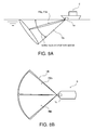
Fig. 8A is a side view of transmission and reception beams formed by an underwater detection apparatus according to a modification, illustrated with the ship on which the underwater detection apparatus is mounted, andFig. 8B is a top view of the transmission and reception beams formed by the underwater detection apparatus according to the modification, illustrated with the ship on which the underwater detection apparatus is mounted; -
Fig. 9 is a top view of transmission and reception beams formed by an underwater detection apparatus according to another modification illustrated with the ship on which the underwater detection apparatus is mounted; and -
Fig. 10 is a top view of transmission and reception beams formed by an underwater detection apparatus according to still another modification illustrated with the ship on which the underwater detection apparatus is mounted. - Hereinafter, an underwater detection apparatus according to one embodiment of this disclosure is described with reference to the appended drawings. The
underwater detection apparatus 1 of this embodiment is a CTFM (Continuous Transmission Frequency Modulated)-type detection apparatus, and for example, it is attached to a bottom of a ship (e.g., a fishing boat) and used mainly for detecting target objects (e.g., a single fish or a school of fish). Theunderwater detection apparatus 1 is also used for detecting undulation of a water bottom, such as a rock reef, and a structural object, such as an artificial fish reef. Moreover, according to theunderwater detection apparatus 1, a target object in 3-dimensional space can be detected. -
Fig. 1 is a block diagram illustrating a configuration of theunderwater detection apparatus 1 of this embodiment. As illustrated inFig. 1 , theunderwater detection apparatus 1 includes a projector 2 (which may also be referred to as a transmitting part of a transducer), asensor 3, a motor 4 (which may also be referred to as a motion mechanism), a transmission-and-reception device 5, asignal processor 10, and adisplay unit 8. - The
projector 2 transmits underwater ultrasonic wave as transmission wave, and is fixed to the bottom of the ship so that a transmittingsurface 2a from which ultrasonic wave is transmitted is exposed to the water and faces vertically downward. In this embodiment, the transmittingsurface 2a is formed into a circular shape. Thus, theprojector 2 of this embodiment is capable of transmitting a 3-dimensional transmission beam VB over a comparatively wide range (i.e., the volume beam). The transmission beam VB has, for example, a conical shape extending downward with the vertex at the projector 2 (in this embodiment, a right conical shape). The opening angle of the conical shape is about 120°. However, this disclosure is not limited as such, and the opening angle may be less than or greater than 120°. For example, the angle may be between 90° and 180°. - Further, a frequency modulated ultrasonic wave may be transmitted from
projector 2. Specifically, the transmission wave is a chirp wave of which frequency gradually changes with time, and theprojector 2 continuously transmits by repeatedly transmitting the chirp wave at a particular time cycle.Fig. 2 is a chart illustrating a relationship between time and frequency of the ultrasonic wave transmitted from theprojector 2. InFig. 2 , Xmax indicates a sweeping time period and Δfmax indicates a sweeping bandwidth. - The
sensor 3 has a plurality of (in this embodiment, two)ultrasonic transducers ultrasonic transducers surfaces ultrasonic transducers projector 2, and converts it into an electric signal (e.g. a received signal). Note that, the illustration of theultrasonic transducers surfaces Fig. 1 . -
Fig. 3A is a bottom view schematically illustrating the twoultrasonic transducers Fig. 1 along with shapes of reception beams FBa and FBb formed by the respectiveultrasonic transducers Fig. 3B is a side view schematically illustrating the twoultrasonic transducers Fig. 1 along with the shapes of the reception beams FBa and FBb formed by the respectiveultrasonic transducers surfaces Figs. 3A and 3B , theultrasonic transducers surfaces surfaces - The receiving surfaces 32a and 32b are arranged to face downward. Specifically, the receiving
surfaces surfaces Fig. 3A , the receivingsurfaces surfaces surfaces ultrasonic transducers - The
motor 4 sets thesensor 3 in motion. Specifically, themotor 4 repeatedly rotates thesensor 3 about a central axis extending vertically at a position between the receivingsurfaces sensor 3 and each of the beam axes of the reception beams FBa and FBb is not a right angle. In this embodiment, this angle is an acute angle. Thesensor 3 rotates within the horizontal plane perpendicular to the vertical direction. Themotor 4 repeatedly rotates thesensor 3 by a particular angle at a particular time interval. -
Fig. 4 is a view schematically illustrating a process of detecting the target object by theunderwater detection apparatus 1, illustrated with the ship S on which theunderwater detection apparatus 1 is mounted. In this embodiment, themotor 4 rotates thesensor 3 to rotate the reception beams FBa and FBb formed by theultrasonic transducers projector 2. Thus, according to theunderwater detection apparatus 1 of this embodiment, the target object in 3-dimensional space below the ship (space surrounded by the dashed lines inFig. 4 ) can be detected. - The transmission-and-
reception device 5 includes atransmitter 6 and areceiver 7. - The
transmitter 6 amplifies the frequency modulated transmission signal generated by thesignal processor 10 to obtain a high-voltage transmission signal, and applies the high-voltage transmission signal to theprojector 2. - The
receiver 7 amplifies the electric signal (received signal) outputted by thesensor 3, and A/D converts the amplified received signal. Then, thereceiver 7 outputs the received signal converted into a digital signal, to thesignal processor 10. Specifically, thereceiver 7 has two receive circuits (not illustrated), and each receive circuit performs the processing described above on the received signal obtained by electroacoustically converting the reflected wave received by the corresponding ultrasonic transducer (31a or 31b), and outputs the processed received signal to thesignal processor 10. - The
signal processor 10 generates the transmission signal (electric signal) and inputs it to thetransmitter 6. Further, thesignal processor 10 processes the received signal outputted by thereceiver 7 to generate an image signal of the target object. The configuration of thesignal processor 10 is described later in detail. - The
display unit 8 displays, on a display screen, an image corresponding to the image signal outputted by thesignal processor 10. In this embodiment, thedisplay unit 8 displays an underwater state below the ship on a PPI (Plan Position Indication) display. Thus, a user can estimate the underwater state below the ship (e.g., a single fish or a school of fish, undulation of the water bottom, whether the structural object, such as an artificial fish reef, exists, and a position thereof) by looking at the display screen. -
Fig. 5 is a block diagram illustrating a configuration of thesignal processor 10. As illustrated inFig. 5 , thesignal processor 10 includes atransmission signal generator 10a, a transmission-and-reception processor 11, and a detection image generator 18 (which may also be referred to as a target object information generator or a target object information generating means). - The
transmission signal generator 10a generates the transmission signal (electric signal), basis of the transmission wave transmitted by theprojector 2. The transmission signal generated by thetransmission signal generator 10a is transmitted to thetransmitter 6 and the transmission-and-reception processor 11. - The transmission-and-
reception processor 11 has two transmission-and-reception circuits reception circuits transmission signal generator 10a and the received signal generated by the corresponding receive circuit (the received signal obtained by the corresponding one of theultrasonic transducers reception circuit 11a receives the received signal obtained by theultrasonic transducer 31a, whereas the transmission-and-reception circuit 11b receives the received signal obtained by theultrasonic transducer 31b. - Each of the transmission-and-
reception circuits first multiplier 12, a low-pass filter 13, asignal extractor 14, awindow function memory 15, asecond multiplier 16, and afrequency analyzer 17. Note that, each of the transmission-and-reception circuits - The
first multiplier 12 generates a beat signal based on the transmission signal generated by thetransmission signal generator 10a and the received signals obtained from the ultrasonic waves received by theultrasonic transducers first multiplier 12 combines (e.g. mixes or multiplies) the transmission signal with the received signals described above to generate the beat signal.Fig. 6 is a chart illustrating one example of the beat signal generated by thefirst multiplier 12. - The low-
pass filter 13 removes an unrequired signal component (which is typically a high frequency component) from the beat signal generated by thefirst multiplier 12. - From the beat signal with the unrequired signal component removed by the low-
pass filter 13, thesignal extractor 14 extracts a signal from within a section so as to process the signal in a post process. Specifically, thesignal extractor 14 sets the section to be processed to be a reception gate section, and sets the beat signal within the reception gate section to be the extracted beat signal.Figs. 7A and 7B are views for describing the generation of the extracted beat signal, in whichFig. 7A illustrates a waveform of the beat signal outputted from the low-pass filter (i.e., a waveform before the extracted beat signal is extracted), andFig. 7B illustrates a waveform of the extracted beat signal extracted from the beat signal inFig. 7A . - The
window function memory 15 stores a particular window function. Further, thesecond multiplier 16 multiplies the extracted beat signal by the particular window function stored in thewindow function memory 15. - The
frequency analyzer 17 analyzes the output result from the second multiplier 16 (the extracted beat signal multiplied by the window function) and generates data indicating an amplitude and a phase (amplitude spectrum and phase spectrum; hereinafter, they may comprehensively be referred to as the complex spectrum) at each frequency. Examples of the analyzing method include a Discrete Fourier Transform (DFT) and a Fast Fourier Transform (FFT). Note that, by multiplying the extracted beat signal by the window function as described above, side lobes of the complex spectrum generated by thefrequency analyzer 17 can be reduced. - Further, in the transmission-and-
reception processor 11, the complex spectra corresponding to theultrasonic transducers reception circuits frequency analyzer 17 is outputted to thedetection image generator 18. - The
detection image generator 18 converts a horizontal axis of the complex spectrum generated by each of the transmission-and-reception circuits - Further, based on the received signal corresponding to a rotational angular position that is gradually changed by the motor 4 (ϕ= ϕ1, ϕ2, ... in
Fig. 4 ), thedetection image generator 18 generates echo data of the respective angular positions, and combines them to generate echo data within a 3-dimensional (right conical, in this embodiment) detection area. Here, the rotational speed of themotor 4 may need to be set so that a time period for rotating by the angle corresponding to the thickness of each of the reception beams FBa and FBb becomes longer than a time period corresponding to the reception gate section at the transmission-and-reception processor 11. In a case of shortening the detection time as much as possible, the rotational speed of themotor 4 may be set so that both of the time periods match with each other. - Hereinafter, a detection time for detecting a target object by the
underwater detection apparatus 1 of this embodiment is compared, through simulation, with a detection time for detecting the target object by a known (general) underwater detection apparatus (underwater detection apparatus using mechanical scanning based on a pulse echo method). When the sensors of the apparatuses require the same number of rotation steps to detect the entire horizontal circumference of the ship, by comparing a time period to receive an echo at a single azimuth, a detection time for the entire circumference can be compared. Therefore, hereinafter, the detection time of theunderwater detection apparatus 1 of this embodiment is compared with that of by the known underwater detection apparatus, by comparing the time period to receive an echo at a single azimuth. The simulation is performed under a condition that the detection range is 25m, a range resolution is 0.19m, and a CTFM sweep bandwidth is 15 kHz. - As a result of simulation under such a condition described above, the detection time of the known underwater detection apparatus to receive an echo at a single azimuth was 33ms. Note that, this value was calculated based on a propagation time of an ultrasonic wave within the detection range. Specifically, the value is obtained by dividing a propagation distance of the ultrasonic wave (twice the detection range, 50m in the simulation described above) by the speed of the ultrasonic wave underwater (1,500m/s).
- Whereas, the detection time of the
underwater detection apparatus 1 was 9ms. Note that, this value was calculated based on the condition of the simulation described above. Specifically, when the detection range is 25m and the range resolution is 0.19m, the range resolution is 1/133 in ratio, and therefore, a value obtained by multiplying the CTFM sweeping bandwidth (15 kHz) by 1/113, 0.11 kHz, is a frequency resolution. A time period to achieve this frequency resolution can be calculated as 9ms by taking an inverse number of 0.11 kHz. - As described above, it was confirmed that about 3.6 times of increase in speed compared to the conventional method (the pulse echo method) could be achieved with the
underwater detection apparatus 1 of this embodiment. - As above, with the
underwater detection apparatus 1 of this embodiment, the detection over the 3-dimensional space within the range of the 3-dimensional transmission beam VB is performed by setting thesensor 3 in motion. Thus, according to theunderwater detection apparatus 1, the detection over the 3-dimensional space can be performed. Moreover, the receiving elements do not need to be arranged 2-dimensionally or 3-dimensionally as they are arranged in a conventional scanning sonar, and a number of receiving elements can be reduced. Therefore, the apparatus can be simplified. - Further, since the
underwater detection apparatus 1 detects the target object by using a CTFM method, compared to the case of adopting the pulse echo method, a time for detecting over a particular range can be shortened. More specifically, since the CTFM method is adopted, theunderwater detection apparatus 1 can receive the ultrasonic wave at a single azimuth in a time period shorter than the time period for the round-trip propagation of the detection range by the ultrasonic pulse. Thus, the echo intensity at a single azimuth can be obtained in a comparatively short time period, and as a result, the time period for detecting the particular range can be shortened. - Further, with the
underwater detection apparatus 1, since the transmission beam VB has the 3-dimensional shape, a single transmission of the ultrasonic wave can cover the detection target area for the target object. In this manner, theprojector 2 does not need to be moved in order to run through the entire detection area. Therefore, the apparatus can be simplified. - Therefore, according to the
underwater detection apparatus 1, a CTFM detection apparatus capable of detecting a target object in 3-dimensional space in a short time period can be provided at low cost. - Further, with the
underwater detection apparatus 1, the 2-dimensional reception beams FBa and FBb are moved in the direction that intersects with the direction in which the 2-dimensional reception beams extend. Therefore, the 3-dimensional space can be scanned with the reception beams FBa and FBb. Furthermore, by forming the reception beams FBa and FBb into a 2-dimensional shape, the target object can be detected in a short time period, for example, compared to the case of scanning within the transmission beam with a pencil-shape reception beam. - Further, with the
underwater detection apparatus 1, the 2-dimensional reception beams FBa and FBb are moved in the direction perpendicular to the direction in which the 2-dimensional reception beams extend. Therefore, the detection can be performed over a comparatively wide 3-dimensional space spreading from theunderwater detection apparatus 1. - Further, with the
underwater detection apparatus 1, by moving the fan-shaped reception beams FBa and FBb, the detection can be performed over a comparatively wide 3-dimensional space below the ship. - Further, with the
underwater detection apparatus 1, the receivingsurfaces - Further, with the
underwater detection apparatus 1, theprojector 2 generates the conically shaped transmission beam VB (in this embodiment, right conical shape), and thesensor 3 scans the range of the transmission beam VB. Therefore, the detection can be performed over a wide range below the ship. - Further, with the
underwater detection apparatus 1, the transmittingsurface 2a is formed into the circular shape. Therefore, the 3-dimensional transmission beam VB can suitably be formed. - Further, with the
underwater detection apparatus 1, thesensor 3 is rotated by themotor 4. Therefore, a CTFM detection apparatus capable of detecting 3-dimensional space can be constructed with a comparatively simple configuration. - Further, with the
underwater detection apparatus 1, each of the angles formed between the rotational axis of thesensor 3 and each of the beam axes of the reception beams FBa and FBb formed by theultrasonic transducers - Further, with the
underwater detection apparatus 1, the receivingsurfaces Fig. 4 ) can be extended. - Further, with the
underwater detection apparatus 1, an underwater detection apparatus capable of detecting a target object in 3-dimensional space in a short time period can be provided at low cost. - Although the embodiment of this disclosure is described above, this disclosure is not limited thereto, and may be modified in various forms without deviating from the scope of this disclosure.
- (1)
Fig. 8A is a side view of transmission and reception beams formed by anunderwater detection apparatus 1a according to a modification, illustrated with the ship S on which theunderwater detection apparatus 1a is mounted, andFig. 8B is a top view of the transmission and reception beams formed by theunderwater detection apparatus 1a according to this modification, illustrated with the ship S on which theunderwater detection apparatus 1a is mounted. Theunderwater detection apparatus 1 of the above embodiment detects below the ship; however, without limiting to this, it may detect a forward area of the ship, for example, as theunderwater detection apparatus 1a of this modification. Specifically, theunderwater detection apparatus 1a of this modification is provided as a forward detection sonar capable of detecting reef, etc., that may cause stranding in the forward area of the ship. Hereinafter, differing points from the above embodiment are mainly described, and description of other points is omitted. Note that, compared to theunderwater detection apparatus 1 of the above embodiment, theunderwater detection apparatus 1a of this modification greatly differs with regard to the area that can be detected, and the configuration thereof is substantially the same as the configuration inFig. 1 . - The
underwater detection apparatus 1a of this modification includes aprojector 2 having a similar configuration to the above embodiment. However, in this modification, theprojector 2 is fixed to a front side of the ship so that a transmitting surface thereof inclines forward of the ship with respect to the vertical direction. Thus, with theunderwater detection apparatus 1a of this modification, a transmission beam VB formed into a volume beam is generated to extend both forward of the ship and underwater. For example, the transmission beam VB is of a conical shape so that it covers 0° to 45° when the horizontal direction is 0° and the vertically downward direction is 90°, and also covers a range from 45° on the starboard side to 45° on the port side. - Further, the
underwater detection apparatus 1a of this modification includes asensor 3 having a similar configuration to the above embodiment. Twoultrasonic transducers sensor 3, similar to the case of theprojector 2, is fixed to the front side of the ship so that a receiving surface thereof inclines forward of the ship with respect to the vertical direction. Thus, with theunderwater detection apparatus 1a of this modification, reception beams FBa and FBb are formed to extend both forward of the ship and underwater. For example, the reception beam FBa of this modification is formed into a 2-dimensional shape in which the thickness in the up-and-down directions is comparatively thin, as thin as about 6°, and covers, when the forward direction is 0°, a range from 45° to 0° on the starboard side. The reception beam FBb is, for example, formed into a 2-dimensional shape in which the thickness in the up-and-down directions is comparatively thin, as thin as about 6°, and covers, when the forward direction is 0°, a range from 0° to 45° on the port side. - Further, the
sensor 3 of this modification is inclined upward or downward by themotor 4 so as to vertically swing back and forth. Thus, the reception beams FBa and FBb can be vertically swung back and forth. Therefore, the detection can be performed 3-dimensionally over the forward area of the ship. - As described above, also by swinging the reception beams FBa and FBb of this modification, similar to the
underwater detection apparatus 1 of the above embodiment, a CTFM detection apparatus capable of detecting a target object in 3-dimensional space in a short time period can be provided at low cost. - Further, with the underwater detection device of this modification, since the
sensor 3 is swung back and forth, a CTFM detection apparatus capable of suitably detecting over a detection area extending in a particular direction (e.g. forward of the ship) can be constructed with a comparatively simple configuration. Note that, in this modification, the direction of arrangement of the twoultrasonic transducers - (2) In the above embodiment, the transmitting
surface 2a is formed into a circular shape so that the transmission beam VB has a right conical shape; however, it is not limited to this. Specifically, for example, the transmitting surface may be formed into an oblong rectangular shape having a particular aspect ratio so that the transmission beam has an elliptical conical shape or other conical shapes. - (3)
Fig. 9 is a top view of a transmission beam VB and a reception beam FB formed by anunderwater detection apparatus 1b according to another modification, illustrated with the ship S on which theunderwater detection apparatus 1b is mounted. With theunderwater detection apparatus 1b of this modification, not only the reception beam FB, but the transmission beam VB is also rotated. Note that inFig. 9 , the reception beams FBa and FBb formed by theultrasonic transducers - As illustrated in
Fig. 9 , the transmission beam VB generated by theunderwater detection apparatus 1b of this modification is generated into a volume beam shape wider (longer in the thickness direction) compared to the reception beam FB (specifically, elliptical conical shape). The volume beam VB with such a shape can be generated, for example, by forming the transmitting surface into an oblong rectangular shape. In the case of this modification, the aspect ratio of the transmitting surface is closer to 1 compared to the aspect ratio of the receiving surface of the receiving element. Further, the transmission beam VB is rotated by the motor in the direction indicated by the arrows inFig. 9 , at the same rotational speed as the reception beam FB. The width (the length in the thickness direction) of the transmission beam VB can be determined based on a ratio of a time period of a reception gate section set by theunderwater detection apparatus 1b of this modification with respect to a time period for the round trip propagation of the detection range by the ultrasonic pulse. For example, if this ratio is 1/3, by setting the transmission beam VB to be wider (longer in the thickness direction) than the range corresponding to three steps of rotation of the reception beam FB (seeFig. 9 ), even when the sensor is rotated without waiting for a return of the reflection wave at a particular rotational angle, the reflection wave can be received at the rotated angle. Therefore also in this modification, similar to the above embodiment, a CTFM detection apparatus capable of detecting a target object in 3-dimensional space in a short time period can be provided at low cost. - Furthermore, according to this modification, the ultrasonic wave transmitted from the projector generating the transmission beam VB is not transmitted to all azimuths, and the transmission wave is transmitted only to the azimuth where the reception of the echo by the sensor is performed. Thus, the transmission wave can be transmitted with concentrated energy to a particular direction. Therefore, an electric power for transmitting the transmission wave can be reduced. Thus, a CTFM detection apparatus effective in saving energy can be provided.
- (4)
Fig. 10 is a top view of a transmission beam VB and a reception beam FB formed by anunderwater detection apparatus 1c according to another modification illustrated with the ship S on which theunderwater detection apparatus 1c is mounted. Theunderwater detection apparatus 1c of this modification has a configuration different from theunderwater detection apparatus 1b inFig. 9 in that one of the twoultrasonic transducers underwater detection apparatus 1c of this modification has one receiving element. - Further, also with the
underwater detection apparatus 1c of this modification, similar to theunderwater detection apparatus 1b inFig. 9 , the transmission beam VB is rotated by the motor in the direction indicated by the arrow inFig. 10 , at the same rotational speed as the reception beam FB. Thus, also with theunderwater detection apparatus 1c including only one receiving element, effects similar to the case of theunderwater detection apparatus 1b inFig. 9 can be obtained. - (5) The transmission-and-
reception processor 11 of the above embodiment includes thewindow function memory 15 and thesecond multiplier 16; however, without limiting to this, the window function memory and the second multiplier may be omitted from the configuration of the transmission-and-reception processor. Thus, deterioration of a resolution of a main lobe can be suppressed. - (6) In the
first multiplier 12 of the transmission-and-reception processor 11 of the above embodiment, the transmission signal generated by thetransmission signal generator 10a and the received signals corresponding to the waveform of the ultrasonic waves received by theultrasonic transducers receiver 7 is reduced can be obtained as the output of the transmission-and-reception processor 11. - (7) In the above embodiment, the combining of the transmission signal with the received signals is performed as the digital signal processing; however, it may be performed as analog signal processing. In this case, the
first multiplier 12 is disposed in the transmission-and-reception device 5 instead of the transmission-and-reception processor 11, and the combining described above is performed before the received signals are A/D converted by thereceiver 7. - (8) In the above embodiment, the frequency modulated continuous wave is transmitted by the
projector 2; however, without limiting to this, a frequency modulated pulse wave having a pulse width corresponding to a time period longer than that of a round-trip propagation of the detection range by the ultrasonic wave may be transmitted by the projector. - (9) In the above embodiment and modifications, the underwater detection apparatus is described as the CTFM detection apparatus as an example; however, without limiting to this, a radar, etc., may be given as the CTFM detection apparatus.
Claims (12)
- A Continuous Transmission Frequency Modulated (CTFM) detection apparatus comprising:a projector (2) configured to transmit a frequency modulated transmission wave and to generate a 3-dimensional transmission beam;a receiving element (31a, 31b) configured to receive a reflected wave, the reflected wave comprising a reflection of the transmission wave;a motion mechanism (4) configured to set the receiving element (31a, 31b) in motion and to make a reception beam formed by the receiving element (31a, 31b) scan a 3-dimensional space within the transmission beam; anda target object information generating means (18) configured to generate information on target objects within the 3-dimensional space based at least in part on a beat signal generated based at least in part on the transmission wave transmitted by the projector (2) and the reflected wave received by the receiving element (31a, 31b).
- The CTFM detection apparatus of claim 1, wherein
the reception beam formed by the receiving element (31a, 31b) is a 2-dimensional reception beam; and
the motion mechanism (4) sets the receiving element (31a, 31b) in motion in a direction that intersects with a direction in which the 2-dimensional reception beam extends. - The CTFM detection apparatus of claim 2, wherein
the motion mechanism (4) sets the receiving element (31a, 31b) in motion in a direction perpendicular to the direction in which the 2-dimensional reception beam extends. - The CTFM detection apparatus of claim 2 or claim 3, wherein
the reception beam formed by the receiving element (31a, 31b) is of a fan shape. - The CTFM detection apparatus of claim 4, wherein
a receiving surface on which the reflected wave is received by the receiving element (31a, 31b) is of a rectangular shape. - The CTFM detection apparatus of any of the preceding claims, wherein
the transmission beam generated by the projector (2) is of a conical shape; and
the reception beam, set in motion by the motion mechanism (4), scans a conical range within the transmission beam. - The CTFM detection apparatus of claim 6, wherein
a transmitting surface from which the transmission wave is transmitted by the projector (2) is of a circular shape. - The CTFM detection apparatus of any of the preceding claims, wherein
the motion mechanism (4) rotates the receiving element (31a, 31b). - The CTFM detection apparatus of claim 8, wherein
an angle formed between a rotational axis of the receiving element (31a, 31b) and a beam axis of the reception beam is an acute angle or an obtuse angle. - The CTFM detection apparatus of any one of claims 1 to 7, wherein
the motion mechanism (4) swings the receiving element (31a, 31b) back and forth. - The CTFM detection apparatus of any of the preceding claims further comprising:a plurality of the receiving elements (31a, 31b); whereinreceiving surfaces on which the reflected wave is received by each of the plurality of receiving elements (31a, 31b) are mutually oriented in different directions.
- An underwater detection apparatus comprising the CTFM detection apparatus of any of the preceding claims.
Applications Claiming Priority (1)
| Application Number | Priority Date | Filing Date | Title |
|---|---|---|---|
| JP2014226659A JP2016090453A (en) | 2014-11-07 | 2014-11-07 | Detection device and underwater detection device |
Publications (1)
| Publication Number | Publication Date |
|---|---|
| EP3018494A1 true EP3018494A1 (en) | 2016-05-11 |
Family
ID=54366152
Family Applications (1)
| Application Number | Title | Priority Date | Filing Date |
|---|---|---|---|
| EP15193062.5A Withdrawn EP3018494A1 (en) | 2014-11-07 | 2015-11-04 | Ctfm detection apparatus and underwater detection apparatus |
Country Status (3)
| Country | Link |
|---|---|
| US (1) | US20160131760A1 (en) |
| EP (1) | EP3018494A1 (en) |
| JP (1) | JP2016090453A (en) |
Cited By (1)
| Publication number | Priority date | Publication date | Assignee | Title |
|---|---|---|---|---|
| US11320534B2 (en) * | 2017-03-10 | 2022-05-03 | Furuno Electric Company Limited | Ultrasonic detecting device and ultrasonic detecting method |
Families Citing this family (6)
| Publication number | Priority date | Publication date | Assignee | Title |
|---|---|---|---|---|
| JP6724593B2 (en) * | 2016-06-22 | 2020-07-15 | 日本電気株式会社 | Active sonar and control method of active sonar |
| JP6722521B2 (en) * | 2016-06-23 | 2020-07-15 | 古野電気株式会社 | Underwater detection system |
| WO2019167563A1 (en) * | 2018-03-02 | 2019-09-06 | 古野電気株式会社 | Underwater detection device and underwater detection method |
| JP7051625B2 (en) * | 2018-07-12 | 2022-04-11 | 古野電気株式会社 | Underwater detector and underwater detection method |
| JP7246251B2 (en) | 2019-05-21 | 2023-03-27 | 古野電気株式会社 | UNDERWATER DETECTION DEVICE AND UNDERWATER DETECTION METHOD |
| TWI908317B (en) * | 2024-09-06 | 2025-12-11 | 台達電子工業股份有限公司 | Rotational speed measurement apparatus and method |
Citations (5)
| Publication number | Priority date | Publication date | Assignee | Title |
|---|---|---|---|---|
| US3939463A (en) * | 1964-02-05 | 1976-02-17 | The United States Of America As Represented By The Secretary Of The Navy | Acoustic transponder navigation system |
| EP0199571A1 (en) * | 1985-04-20 | 1986-10-29 | Peter Travis Gough | Continuous transmission synthetic aperture sonar |
| US4862427A (en) * | 1987-12-22 | 1989-08-29 | Ketema, Inc. | Sonar system with area moving target indicator |
| US20050007882A1 (en) * | 2003-07-11 | 2005-01-13 | Blue View Technologies, Inc. | Systems and methods implementing frequency-steered acoustic arrays for 2D and 3D imaging |
| US20130215719A1 (en) | 2012-02-22 | 2013-08-22 | Johnson Outdoors Inc. | 360 Degree Imaging Sonar and Method |
-
2014
- 2014-11-07 JP JP2014226659A patent/JP2016090453A/en active Pending
-
2015
- 2015-11-04 EP EP15193062.5A patent/EP3018494A1/en not_active Withdrawn
- 2015-11-05 US US14/933,496 patent/US20160131760A1/en not_active Abandoned
Patent Citations (5)
| Publication number | Priority date | Publication date | Assignee | Title |
|---|---|---|---|---|
| US3939463A (en) * | 1964-02-05 | 1976-02-17 | The United States Of America As Represented By The Secretary Of The Navy | Acoustic transponder navigation system |
| EP0199571A1 (en) * | 1985-04-20 | 1986-10-29 | Peter Travis Gough | Continuous transmission synthetic aperture sonar |
| US4862427A (en) * | 1987-12-22 | 1989-08-29 | Ketema, Inc. | Sonar system with area moving target indicator |
| US20050007882A1 (en) * | 2003-07-11 | 2005-01-13 | Blue View Technologies, Inc. | Systems and methods implementing frequency-steered acoustic arrays for 2D and 3D imaging |
| US20130215719A1 (en) | 2012-02-22 | 2013-08-22 | Johnson Outdoors Inc. | 360 Degree Imaging Sonar and Method |
Non-Patent Citations (1)
| Title |
|---|
| CTFM SONAR SS330, 29 August 2014 (2014-08-29), Retrieved from the Internet <URL:http://www.sunwest-tech.com/SS300%20Broch%20-%20REV%20G.pdf> |
Cited By (1)
| Publication number | Priority date | Publication date | Assignee | Title |
|---|---|---|---|---|
| US11320534B2 (en) * | 2017-03-10 | 2022-05-03 | Furuno Electric Company Limited | Ultrasonic detecting device and ultrasonic detecting method |
Also Published As
| Publication number | Publication date |
|---|---|
| JP2016090453A (en) | 2016-05-23 |
| US20160131760A1 (en) | 2016-05-12 |
Similar Documents
| Publication | Publication Date | Title |
|---|---|---|
| EP3018493A1 (en) | Ctfm detection apparatus and underwater detection apparatus | |
| EP3018494A1 (en) | Ctfm detection apparatus and underwater detection apparatus | |
| US10215849B2 (en) | CTFM detection apparatus and underwater detection apparatus | |
| Colbo et al. | A review of oceanographic applications of water column data from multibeam echosounders | |
| US20130083628A1 (en) | Imaging system and method | |
| US11320534B2 (en) | Ultrasonic detecting device and ultrasonic detecting method | |
| US20180224544A1 (en) | Forward scanning sonar system and method with angled fan beams | |
| EP3153881A1 (en) | Detection apparatus, fish finder, and radar | |
| US9636086B2 (en) | Three dimensional (3D) transverse oscillation vector velocity ultrasound imaging | |
| JP7262298B2 (en) | UNDERWATER DETECTION DEVICE AND UNDERWATER DETECTION METHOD | |
| US9474510B2 (en) | Ultrasound and system for forming an ultrasound image | |
| KR0180057B1 (en) | 3D image acquisition device of ultrasonic system | |
| AU2016300222A1 (en) | Forward scanning sonar system and method with angled fan beams | |
| EP3570069A1 (en) | Method of compressing beamformed sonar data | |
| JP5767002B2 (en) | Ultrasonic transmission / reception device and fish quantity detection method | |
| CA2993361A1 (en) | Forward scanning sonar system and method with angled fan beams | |
| Wei et al. | Theoretical and experimental study on multibeam synthetic aperture sonar | |
| WO2014147122A1 (en) | Imaging system and method | |
| JP7813244B2 (en) | Target detection device and target detection method | |
| JP6088165B2 (en) | Detection device, detection method, and detection program | |
| JP2014020907A (en) | Underwater detection device, underwater detection method and program | |
| JP2012112922A (en) | Detection device, and device, method and program for hydrospace detection | |
| Holmin et al. | Estimation and simulation of multi-beam sonar noise | |
| WO2011058527A1 (en) | Method and apparatus for processing sonar signals | |
| Kouzoubov et al. | Acoustic imaging of surface ship wakes |
Legal Events
| Date | Code | Title | Description |
|---|---|---|---|
| PUAI | Public reference made under article 153(3) epc to a published international application that has entered the european phase |
Free format text: ORIGINAL CODE: 0009012 |
|
| AK | Designated contracting states |
Kind code of ref document: A1 Designated state(s): AL AT BE BG CH CY CZ DE DK EE ES FI FR GB GR HR HU IE IS IT LI LT LU LV MC MK MT NL NO PL PT RO RS SE SI SK SM TR |
|
| AX | Request for extension of the european patent |
Extension state: BA ME |
|
| 17P | Request for examination filed |
Effective date: 20161102 |
|
| RBV | Designated contracting states (corrected) |
Designated state(s): AL AT BE BG CH CY CZ DE DK EE ES FI FR GB GR HR HU IE IS IT LI LT LU LV MC MK MT NL NO PL PT RO RS SE SI SK SM TR |
|
| 17Q | First examination report despatched |
Effective date: 20191213 |
|
| STAA | Information on the status of an ep patent application or granted ep patent |
Free format text: STATUS: THE APPLICATION IS DEEMED TO BE WITHDRAWN |
|
| 18D | Application deemed to be withdrawn |
Effective date: 20200603 |