EP3018401A1 - Vehicle lighting unit - Google Patents
Vehicle lighting unit Download PDFInfo
- Publication number
- EP3018401A1 EP3018401A1 EP15191086.6A EP15191086A EP3018401A1 EP 3018401 A1 EP3018401 A1 EP 3018401A1 EP 15191086 A EP15191086 A EP 15191086A EP 3018401 A1 EP3018401 A1 EP 3018401A1
- Authority
- EP
- European Patent Office
- Prior art keywords
- light
- face
- light rays
- led
- lighting unit
- Prior art date
- Legal status (The legal status is an assumption and is not a legal conclusion. Google has not performed a legal analysis and makes no representation as to the accuracy of the status listed.)
- Granted
Links
Images


Classifications
-
- F—MECHANICAL ENGINEERING; LIGHTING; HEATING; WEAPONS; BLASTING
- F21—LIGHTING
- F21S—NON-PORTABLE LIGHTING DEVICES; SYSTEMS THEREOF; VEHICLE LIGHTING DEVICES SPECIALLY ADAPTED FOR VEHICLE EXTERIORS
- F21S41/00—Illuminating devices specially adapted for vehicle exteriors, e.g. headlamps
- F21S41/10—Illuminating devices specially adapted for vehicle exteriors, e.g. headlamps characterised by the light source
- F21S41/14—Illuminating devices specially adapted for vehicle exteriors, e.g. headlamps characterised by the light source characterised by the type of light source
- F21S41/141—Light emitting diodes [LED]
- F21S41/143—Light emitting diodes [LED] the main emission direction of the LED being parallel to the optical axis of the illuminating device
-
- F—MECHANICAL ENGINEERING; LIGHTING; HEATING; WEAPONS; BLASTING
- F21—LIGHTING
- F21S—NON-PORTABLE LIGHTING DEVICES; SYSTEMS THEREOF; VEHICLE LIGHTING DEVICES SPECIALLY ADAPTED FOR VEHICLE EXTERIORS
- F21S41/00—Illuminating devices specially adapted for vehicle exteriors, e.g. headlamps
- F21S41/10—Illuminating devices specially adapted for vehicle exteriors, e.g. headlamps characterised by the light source
- F21S41/14—Illuminating devices specially adapted for vehicle exteriors, e.g. headlamps characterised by the light source characterised by the type of light source
- F21S41/141—Light emitting diodes [LED]
- F21S41/151—Light emitting diodes [LED] arranged in one or more lines
-
- F—MECHANICAL ENGINEERING; LIGHTING; HEATING; WEAPONS; BLASTING
- F21—LIGHTING
- F21S—NON-PORTABLE LIGHTING DEVICES; SYSTEMS THEREOF; VEHICLE LIGHTING DEVICES SPECIALLY ADAPTED FOR VEHICLE EXTERIORS
- F21S41/00—Illuminating devices specially adapted for vehicle exteriors, e.g. headlamps
- F21S41/20—Illuminating devices specially adapted for vehicle exteriors, e.g. headlamps characterised by refractors, transparent cover plates, light guides or filters
- F21S41/24—Light guides
-
- F—MECHANICAL ENGINEERING; LIGHTING; HEATING; WEAPONS; BLASTING
- F21—LIGHTING
- F21S—NON-PORTABLE LIGHTING DEVICES; SYSTEMS THEREOF; VEHICLE LIGHTING DEVICES SPECIALLY ADAPTED FOR VEHICLE EXTERIORS
- F21S43/00—Signalling devices specially adapted for vehicle exteriors, e.g. brake lamps, direction indicator lights or reversing lights
- F21S43/10—Signalling devices specially adapted for vehicle exteriors, e.g. brake lamps, direction indicator lights or reversing lights characterised by the light source
- F21S43/13—Signalling devices specially adapted for vehicle exteriors, e.g. brake lamps, direction indicator lights or reversing lights characterised by the light source characterised by the type of light source
- F21S43/14—Light emitting diodes [LED]
-
- F—MECHANICAL ENGINEERING; LIGHTING; HEATING; WEAPONS; BLASTING
- F21—LIGHTING
- F21S—NON-PORTABLE LIGHTING DEVICES; SYSTEMS THEREOF; VEHICLE LIGHTING DEVICES SPECIALLY ADAPTED FOR VEHICLE EXTERIORS
- F21S43/00—Signalling devices specially adapted for vehicle exteriors, e.g. brake lamps, direction indicator lights or reversing lights
- F21S43/20—Signalling devices specially adapted for vehicle exteriors, e.g. brake lamps, direction indicator lights or reversing lights characterised by refractors, transparent cover plates, light guides or filters
- F21S43/235—Light guides
- F21S43/236—Light guides characterised by the shape of the light guide
- F21S43/239—Light guides characterised by the shape of the light guide plate-shaped
-
- F—MECHANICAL ENGINEERING; LIGHTING; HEATING; WEAPONS; BLASTING
- F21—LIGHTING
- F21S—NON-PORTABLE LIGHTING DEVICES; SYSTEMS THEREOF; VEHICLE LIGHTING DEVICES SPECIALLY ADAPTED FOR VEHICLE EXTERIORS
- F21S43/00—Signalling devices specially adapted for vehicle exteriors, e.g. brake lamps, direction indicator lights or reversing lights
- F21S43/20—Signalling devices specially adapted for vehicle exteriors, e.g. brake lamps, direction indicator lights or reversing lights characterised by refractors, transparent cover plates, light guides or filters
- F21S43/235—Light guides
- F21S43/242—Light guides characterised by the emission area
- F21S43/243—Light guides characterised by the emission area emitting light from one or more of its extremities
-
- F—MECHANICAL ENGINEERING; LIGHTING; HEATING; WEAPONS; BLASTING
- F21—LIGHTING
- F21S—NON-PORTABLE LIGHTING DEVICES; SYSTEMS THEREOF; VEHICLE LIGHTING DEVICES SPECIALLY ADAPTED FOR VEHICLE EXTERIORS
- F21S43/00—Signalling devices specially adapted for vehicle exteriors, e.g. brake lamps, direction indicator lights or reversing lights
- F21S43/20—Signalling devices specially adapted for vehicle exteriors, e.g. brake lamps, direction indicator lights or reversing lights characterised by refractors, transparent cover plates, light guides or filters
- F21S43/26—Refractors, transparent cover plates, light guides or filters not provided in groups F21S43/235 - F21S43/255
-
- G—PHYSICS
- G02—OPTICS
- G02B—OPTICAL ELEMENTS, SYSTEMS OR APPARATUS
- G02B6/00—Light guides; Structural details of arrangements comprising light guides and other optical elements, e.g. couplings
- G02B6/0001—Light guides; Structural details of arrangements comprising light guides and other optical elements, e.g. couplings specially adapted for lighting devices or systems
- G02B6/0011—Light guides; Structural details of arrangements comprising light guides and other optical elements, e.g. couplings specially adapted for lighting devices or systems the light guides being planar or of plate-like form
- G02B6/0013—Means for improving the coupling-in of light from the light source into the light guide
- G02B6/0015—Means for improving the coupling-in of light from the light source into the light guide provided on the surface of the light guide or in the bulk of it
- G02B6/0016—Grooves, prisms, gratings, scattering particles or rough surfaces
-
- G—PHYSICS
- G02—OPTICS
- G02B—OPTICAL ELEMENTS, SYSTEMS OR APPARATUS
- G02B6/00—Light guides; Structural details of arrangements comprising light guides and other optical elements, e.g. couplings
- G02B6/0001—Light guides; Structural details of arrangements comprising light guides and other optical elements, e.g. couplings specially adapted for lighting devices or systems
- G02B6/0011—Light guides; Structural details of arrangements comprising light guides and other optical elements, e.g. couplings specially adapted for lighting devices or systems the light guides being planar or of plate-like form
- G02B6/0033—Means for improving the coupling-out of light from the light guide
- G02B6/005—Means for improving the coupling-out of light from the light guide provided by one optical element, or plurality thereof, placed on the light output side of the light guide
- G02B6/0051—Diffusing sheet or layer
-
- G—PHYSICS
- G02—OPTICS
- G02B—OPTICAL ELEMENTS, SYSTEMS OR APPARATUS
- G02B6/00—Light guides; Structural details of arrangements comprising light guides and other optical elements, e.g. couplings
- G02B6/0001—Light guides; Structural details of arrangements comprising light guides and other optical elements, e.g. couplings specially adapted for lighting devices or systems
- G02B6/0011—Light guides; Structural details of arrangements comprising light guides and other optical elements, e.g. couplings specially adapted for lighting devices or systems the light guides being planar or of plate-like form
- G02B6/0066—Light guides; Structural details of arrangements comprising light guides and other optical elements, e.g. couplings specially adapted for lighting devices or systems the light guides being planar or of plate-like form characterised by the light source being coupled to the light guide
- G02B6/0068—Arrangements of plural sources, e.g. multi-colour light sources
-
- G—PHYSICS
- G02—OPTICS
- G02B—OPTICAL ELEMENTS, SYSTEMS OR APPARATUS
- G02B6/00—Light guides; Structural details of arrangements comprising light guides and other optical elements, e.g. couplings
- G02B6/0001—Light guides; Structural details of arrangements comprising light guides and other optical elements, e.g. couplings specially adapted for lighting devices or systems
- G02B6/0011—Light guides; Structural details of arrangements comprising light guides and other optical elements, e.g. couplings specially adapted for lighting devices or systems the light guides being planar or of plate-like form
- G02B6/0066—Light guides; Structural details of arrangements comprising light guides and other optical elements, e.g. couplings specially adapted for lighting devices or systems the light guides being planar or of plate-like form characterised by the light source being coupled to the light guide
- G02B6/0073—Light emitting diode [LED]
-
- G—PHYSICS
- G02—OPTICS
- G02B—OPTICAL ELEMENTS, SYSTEMS OR APPARATUS
- G02B6/00—Light guides; Structural details of arrangements comprising light guides and other optical elements, e.g. couplings
- G02B6/0001—Light guides; Structural details of arrangements comprising light guides and other optical elements, e.g. couplings specially adapted for lighting devices or systems
- G02B6/0011—Light guides; Structural details of arrangements comprising light guides and other optical elements, e.g. couplings specially adapted for lighting devices or systems the light guides being planar or of plate-like form
- G02B6/0075—Arrangements of multiple light guides
- G02B6/0078—Side-by-side arrangements, e.g. for large area displays
Definitions
- the present invention relates to vehicle lighting units to be installed on a vehicle body, and in particular, a vehicle lighting unit having an elongated line-shaped (linear or curved) light emitting part.
- Some conventionally known vehicle lighting units to be installed on a vehicle body can include those capable of emitting light rays in an elongated line shape by means of a light guiding bar that has a relatively simple configuration.
- the use of the light guiding bar may possess difficulty in accurate light distribution control, resulting in reduction of the light utilization efficiency.
- the light incident face of such a light guiding bar in front of which a light source can be disposed is essentially limited to both end faces in the longitudinal direction. This configuration makes it difficult to obtain brighter light with high intensity.
- a light guiding lens capable of controlling light distribution with higher accuracy than the light guiding bar is used instead.
- such a light guiding lens of a so-called diffusion type can be configured to have a recessed light incident face for receiving light from a light source to diffuse the received light in the lengthwise direction.
- another known light guiding lens can have a convex face at the center thereof in front of the light source, and the entering light rays can be made parallel by the convex face.
- the light guiding lens can further have side faces on both sides of the convex face where the entering light rays can be guided to total reflection faces to be totally reflected forward.
- Such a total-reflection type light guiding lens is disclosed, for example, Japanese Patent Application Laid-Open No. 2013-257947 .
- LEDs can generally have a directivity in which the light intensity thereof is decreased as the emission angle becomes large, thereby emitting high intensity light designed around its optical axis at its front center.
- a vehicle lighting unit can achieve line-shaped light emission with reduced luminance unevenness more than the conventional ones.
- a vehicle lighting unit can include: an LED having an optical axis in an illumination direction thereof as a forward direction; and a light guiding lens having a plate shape and disposed in front of the LED.
- the light guiding lens can have a light incident face formed at a rear end thereof, and a light exiting face formed at a front end thereof and having an elongated face extending along a plane substantially perpendicular to a front-rear direction.
- the light incident face can have a cross section taken along a plane along a longitudinal direction of the light exiting face in the front-rear direction, the cross section including a center recessed portion configured to receive light rays emitted from the LED around the optical axis thereof to diffuse the light rays toward the light exiting face in the elongated direction, and two convex portions disposed on both sides of the recessed portion, configured to receive light rays emitted from the LED sideward more than those directed to the recessed portion to condense the light rays forward substantially along the front-rear direction.
- the light incident face can further have a cross section taken along a plane perpendicular to the longitudinal direction of the light exiting face, the cross section including a convex face configured to receive the light rays from the LED to make the light rays parallel to one another substantially along the front-rear direction.
- the vehicle lighting unit according to the previous aspect can be configured such that the light exiting face can include a plurality of prism cuts formed thereon, the prism cuts configured to make the light rays guided from the light incident face parallel substantially along the front-rear direction.
- the vehicle lighting unit can be configured to further include a diffusion lens disposed in front of the light guiding lens, configured to diffuse the light rays exiting from the light guiding lens while allowing the light rays to pass therethrough forward.
- a diffusion lens disposed in front of the light guiding lens, configured to diffuse the light rays exiting from the light guiding lens while allowing the light rays to pass therethrough forward.
- the vehicle lighting unit can be configured to include a plurality of the LEDs and a plurality of the light guiding lenses corresponding to the respective LEDs, the light exiting faces of the light guiding lenses being disposed to be continued to each other along the lengthwise direction of the light exiting face.
- the vehicle lighting unit according to the previous aspect can be configured such that at least one of the plurality of light guiding lenses can be curved in a thickness direction thereof.
- the light rays incident on the center recessed portion of the light incident face around the optical axis can be diffused by the center recessed portion around the optical axis in the longitudinal direction (left-right direction) of the light exiting face in the cross section taken along the plane substantially along the longitudinal direction of the light exiting face while the light rays incident on the two convex portions disposed on both sides of the center recessed portion can be condensed forward substantially along the front-rear direction.
- the light rays from the LED when seen in the cross section taken along the plane substantially perpendicular to the longitudinal direction of the light exiting face can be made parallel to one another substantially along the front-rear direction.
- the light rays emitted from the LED and having relatively high intensity around the optical axis can be diffused in the longitudinal direction of the light exiting face while the light rays having low intensity directed sideward with respect to the optical axis can be directed to both sides rather than forward of the LED.
- the vehicle lighting unit can achieve line-shaped light emission with reduced luminance unevenness more than the conventional ones in which portions of the light emission portion just in front of the LED project high intensity of light.
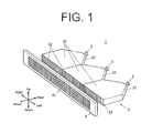
- FIG. 1 is a perspective view of essential parts of a vehicle lighting unit 1 made in accordance with principles of the present invention.
- FIG. 2 is a plan view of parts corresponding to each LED in the vehicle lighting unit 1.
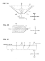
- FIGs. 3A, 3B, and 3C are an enlarged view of part A in FIG. 2 ; a cross-sectional view taken along line B-B in FIG. 2 ; and an enlarged view of part C in FIG. 2 , respectively.
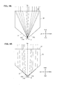
- FIGs. 4A and 4B are each a schematic flat view illustrating the manner in which the light rays are refracted at a light incident face 31 of a light guiding lens 30.
- the directions used herein are defined so that the direction in which light rays travel is the front side (forward direction), and the flat plate shape of the light guiding lens 30 is spread in the horizontal direction (including left-right direction and front-rear direction) and its thickness direction is the vertical direction perpendicular to the horizontal direction.
- the vehicle lighting unit 1 can include a plurality of light emitting diodes (LEDs) 2 (in the present exemplary embodiment, three LEDs), and a light guiding lens unit 3 corresponding to the plurality of LEDs 2, and a diffusion lens 4.
- LEDs light emitting diodes
- the light guiding lens unit 3 corresponding to the plurality of LEDs 2, and a diffusion lens 4.
- Each of the LEDs 2 can be disposed such that an optical axis Ax thereof is directed forward substantially in a front-rear direction. Then, the three LEDs 2 can be arranged side by side at equal intervals along in a left-right direction. Each of the LEDs 2 can emit light rays forward and substantially radially around the optical axis Ax. Incidentally, each of the LEDs 2 can have a directivity of light rays in which the intensity of light rays is lowered as the emission angle is larger with respect to the optical axis Ax.
- the light guiding lens unit 3 can control light rays emitted from the respective LEDs 2 and be disposed in front of the LEDs 2.
- the light guiding lens unit 3 can include a plurality of light guiding lenses 30 (three in the present exemplary embodiment) disposed in front of the corresponding LEDs 2 and side by side. Specifically, light exiting faces 32 of the light guiding lenses 30 can be configured to be continued to each other in the left-right direction.
- Each of the light guiding lenses 30 can have a flat plate shape or a home base shape in a plane view having a steeple on the rear side and a substantially constant thickness.
- the extending direction in which the plate shape extends can be perpendicular to the vertical direction.
- each of the light guiding lenses 30 can be disposed such that the optical axis Ax of the LED 2 passes through the vertical and horizontal (left-right) center of each of the light guiding lenses 30.
- the shape of the light guiding lenses 30 can be designed to be symmetric in the vertical direction as well as in the left-right direction.
- Each of the light guiding lenses 30 can include a light incident face 31 at its steeple on the rear side to receive the light rays from the LED 2, and a light exiting face 32 on the front side, perpendicular to the front-to-rear direction, so that the light rays entering through the light incident face 31 is guided through the light guiding lens 30 to exit through the light exiting face 32 forward.
- the light incident face 31 can receive the light rays from the LED 2 to uniformly spread the light rays in the left-right direction along the horizontal cross section (cross section substantially taken along the horizontal direction) while making the light rays parallel to one another along the vertical cross section (cross section substantially taken along the vertical direction perpendicular to the horizontal direction). Thereby, the light rays can enter the light guiding lens 30.
- the horizontal cross section of the light incident face 31 is formed as follows.
- the light incident face 31 can include a center recessed portion 31a opened rearward and two projected portions 31b disposed on both sides of the recessed portion 31a.
- the projected portion 31b can extend from the recessed portion 31a and be projected rearward, and then curved obliquely forward and sideward, thereby forming a smoothly continued two-humped shape.
- connection points (or the apexes of the two-humped structure) between the recessed portion 31a and two projected portions 31b can be designed such that they are separated away from each other in the left-right direction as the points move from the horizontal plane passing through the optical axis Ax (vertical center) toward both sides in the vertical direction.
- the two connection points are preferably positioned on the horizontal plane at the vertical center passing through the optical axis Ax such that the emission angles of the light rays as seen from the LED 2 side are 1/2 to 3/2 times the half-value angle, and in the present exemplary embodiment, the two connection points can be positioned such that the emission angles substantially become the half-value angle.
- the center recessed portion 31a can be designed such that the light rays emitted from the LED 2 can enter the light guiding lens 30 while the light rays with relatively high intensity around the optical axis Ax are diffused (refracted) horizontally (in the left-right direction) to be spread over the entire light exiting face 32.
- the two projected portions 31b can be configured such that the light rays emitted from the LED 2 directed sideward more than those toward the recessed portion 31a, having relatively low intensity, can enter the light guiding lens 30 therethrough while the light rays can be gathered (refracted) along the front-rear direction toward the light exiting face 32.
- the vertical cross section of the light incident face 31 can be formed to be projected rearward with the portion at the vertical center (vertical direction with respect to the optical axis Ax) being an apex.
- This light incident face 31 with the vertical cross section can receive the light rays emitted from the LED 2 while the light rays are made substantially parallel to the optical axis Ax, whereby the light rays are allowed to enter the light guiding lens 30.
- the light exiting face 32 as illustrated in FIG. 2 can be an elongated surface disposed in front of the light incident face 31 and extending in the left-right direction.
- the light rays entering through the light incident face 31 and guided by the light guiding lens 30 can be further refracted to exit therethrough as parallel light rays substantially to the optical axis Ax (front-rear direction).
- the light exiting face 32 can have a plurality of prism cuts 32a formed on the entire surface of a standard face and disposed side by side in the left-right direction.
- the standard face can be defined as a flat face perpendicular to the front-rear direction and extending in the left-right direction.
- the plurality of prism cuts 32a can be configured to make the light rays from the light incident face 31, mainly from the recessed portion 31a (as illustrated in FIG. 4A ), parallel to one another.
- the plurality of prism cuts 32a can each have a plane inclined with a larger angle at a position away more from the optical axis Ax in the left-right direction as illustrated in FIG. 3C .
- the diffusion lens 4 can be formed in an elongated plate shape extending in the left-right direction so as to cover the light guiding lens unit 3 from its front side, as illustrated in FIGs. 1 and 2 .
- Part of the front face of the diffusion lens 4 substantially covering the entire light exiting faces 32 of the light guiding lens unit 3 can serve as a diffusion face 41 configured to diffuse light rays from the light guiding lens unit 3 in the vertical and horizontal directions.
- the diffusion face 41 of the diffusion lens 4 can include a plurality of diffusion lens cuts 41a formed on the entire surface thereof.
- the diffusion face 41 can include a plurality of projected fish-eye lens cuts arranged in a matrix shape.
- the diffusion lens 4 can diffuse the parallel light rays projected forward through the light guiding lens unit 3 (the plurality of light guiding lenses 30), in the vertical and horizontal directions by means of the plurality of diffusion lens cuts 41a of the diffusion face 41.
- This configuration can achieve the uniform illumination of the diffusion face 41 of the horizontally elongated diffusion lens 4.
- the light rays incident on the center recessed portion 31a of the light incident face 31 around the optical axis Ax can be diffused by the center recessed portion 31a around the optical axis Ax in the left-right direction of the light exiting face in the cross section taken along the plane along the longitudinal direction (left-right direction) of the light exiting face 32 while the light rays incident on the two convex portions 31b disposed on both sides of the center recessed portion 31a can be condensed forward substantially along the front-rear direction.
- the light rays from the LED 2 when seen in the vertical cross section taken along the plane perpendicular to the left-right direction of the light exiting face 32 can be made parallel to one another substantially along the front-rear direction.
- the light rays emitted from the LED 2 and having relatively high intensity around the optical axis Ax can be diffused in the left-right direction of the light incident face 31 while the light rays having low intensity sideward with respect to the optical axis Ax can be directed to both sides rather than forward of the LED 2.
- the vehicle lighting unit 1 can achieve line-shaped (straight lined) light emission with reduced luminance unevenness more than the conventional ones in which portions of the light emission portion just in front of the LED project high intensity of light.
- the light exiting face 32 of the light guiding lens 30 can include the plurality of prism cuts 32a.
- the prism cuts 32a can be configured to make the light rays guided from the light incident face 31 parallel substantially along the front-rear direction. Therefore, the light exiting face 32 of the light guiding lens 30 can project the parallel light rays exiting therethrough with a uniform distribution.
- the diffusion lens 4 can be disposed in front of the light guiding lens(es) 30 in order to diffuse the light rays exiting from the light guiding lens(es) 30 while allowing the light rays to pass therethrough forward. Since the parallel light rays exiting through the light exiting face 32 with the uniform distribution can be diffused by the diffusion lens 4, the vehicle lighting unit can achieve more uniform illumination of the front face (diffusion face 41) of the diffusion lens 4.
- a plate-shaped light guiding lens 30 is used to achieve linear light emission.
- a curved plate-shaped light guiding lens 30A having a curved light exiting face 32A can be utilized to achieve curved linear light emission.
- the light guiding lens 30A can be configured to make the light guiding lens 30 of the above exemplary embodiment curved in the vertical direction (or in the thickness direction), so that the light rays emitted from the corresponding LED 2 can be projected forward through the entire surface of the curved light exiting face 32A.
- FIG. 6 is a perspective view illustrating a variation of a vehicle lighting unit using the light guiding lenses 30A of FIG. 5 .
- a plurality of the light guiding lenses 30A can be arranged to be continued in the lengthwise direction to form a circular arc emission shape as a whole. They can be used in combination with a circular arc shaped diffusion lens 4A disposed in front of the light guiding lenses 30A. With this configuration, the circular arc front face of the diffusion lens 4A can be uniformly illuminated with light from the light guiding lenses 30A.
- each arc shape of the light guiding lens 30A By adjusting the radius of curvature of each arc shape of the light guiding lens 30A and the manner of connection between them, light emission in the shape of a perfect circle, an oval, etc. can be achieved.
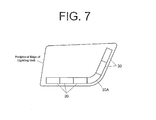
- FIG. 7 is a perspective view illustrating another variation of a vehicle lighting unit in the present exemplary embodiment, wherein a plurality of plate-shaped light guiding lenses 30 and a curved light guiding lens 30A are used along a peripheral edge of a lighting unit. This configuration can achieve a line-shaped emission portion along a lighting unit even having a complex curved shape.
Landscapes
- Physics & Mathematics (AREA)
- Engineering & Computer Science (AREA)
- Optics & Photonics (AREA)
- General Engineering & Computer Science (AREA)
- General Physics & Mathematics (AREA)
- Microelectronics & Electronic Packaging (AREA)
- Non-Portable Lighting Devices Or Systems Thereof (AREA)
Abstract
Description
- The present invention relates to vehicle lighting units to be installed on a vehicle body, and in particular, a vehicle lighting unit having an elongated line-shaped (linear or curved) light emitting part.
- Some conventionally known vehicle lighting units to be installed on a vehicle body can include those capable of emitting light rays in an elongated line shape by means of a light guiding bar that has a relatively simple configuration.
- However, the use of the light guiding bar may possess difficulty in accurate light distribution control, resulting in reduction of the light utilization efficiency. In addition, since the light incident face of such a light guiding bar in front of which a light source can be disposed is essentially limited to both end faces in the longitudinal direction. This configuration makes it difficult to obtain brighter light with high intensity.
- Therefore, when light with high intensity is required, a light guiding lens capable of controlling light distribution with higher accuracy than the light guiding bar is used instead.
- In general, such a light guiding lens of a so-called diffusion type can be configured to have a recessed light incident face for receiving light from a light source to diffuse the received light in the lengthwise direction.
- Further, another known light guiding lens can have a convex face at the center thereof in front of the light source, and the entering light rays can be made parallel by the convex face. The light guiding lens can further have side faces on both sides of the convex face where the entering light rays can be guided to total reflection faces to be totally reflected forward. Such a total-reflection type light guiding lens is disclosed, for example, Japanese Patent Application Laid-Open No.
2013-257947 - Recent trend of light sources for use in vehicle lighting unit includes the application of a light emitting diode (LED) excellent in environmental performances. LEDs can generally have a directivity in which the light intensity thereof is decreased as the emission angle becomes large, thereby emitting high intensity light designed around its optical axis at its front center.
- Under such a circumstance, when such an LED is used in the system including the conventional diffusion type or total-reflection type light guiding lens, the high intensity light rays emitted from an LED around its optical axis cannot be properly controlled. As a result, the portion of a light emission face just in front of the LED may be brighter than the other portion, resulting in luminance unevenness.
- The present invention was devised in view of these and other problems and features in association with the conventional art. According to an aspect of the present invention, a vehicle lighting unit can achieve line-shaped light emission with reduced luminance unevenness more than the conventional ones.
- According to another aspect of the present invention, a vehicle lighting unit can include: an LED having an optical axis in an illumination direction thereof as a forward direction; and a light guiding lens having a plate shape and disposed in front of the LED. The light guiding lens can have a light incident face formed at a rear end thereof, and a light exiting face formed at a front end thereof and having an elongated face extending along a plane substantially perpendicular to a front-rear direction. The light incident face can have a cross section taken along a plane along a longitudinal direction of the light exiting face in the front-rear direction, the cross section including a center recessed portion configured to receive light rays emitted from the LED around the optical axis thereof to diffuse the light rays toward the light exiting face in the elongated direction, and two convex portions disposed on both sides of the recessed portion, configured to receive light rays emitted from the LED sideward more than those directed to the recessed portion to condense the light rays forward substantially along the front-rear direction. The light incident face can further have a cross section taken along a plane perpendicular to the longitudinal direction of the light exiting face, the cross section including a convex face configured to receive the light rays from the LED to make the light rays parallel to one another substantially along the front-rear direction.
- According to another aspect of the present invention, the vehicle lighting unit according to the previous aspect can be configured such that the light exiting face can include a plurality of prism cuts formed thereon, the prism cuts configured to make the light rays guided from the light incident face parallel substantially along the front-rear direction.
- According to still another aspect of the present invention, the vehicle lighting unit according to any of the previous aspects can be configured to further include a diffusion lens disposed in front of the light guiding lens, configured to diffuse the light rays exiting from the light guiding lens while allowing the light rays to pass therethrough forward.
- According to still another aspect of the present invention, the vehicle lighting unit according to any of the previous aspects can be configured to include a plurality of the LEDs and a plurality of the light guiding lenses corresponding to the respective LEDs, the light exiting faces of the light guiding lenses being disposed to be continued to each other along the lengthwise direction of the light exiting face.
- According to still another aspect of the present invention, the vehicle lighting unit according to the previous aspect can be configured such that at least one of the plurality of light guiding lenses can be curved in a thickness direction thereof.
- When the light rays emitted from the LED are incident on the light incident face to enter the light guiding lens, the light rays incident on the center recessed portion of the light incident face around the optical axis can be diffused by the center recessed portion around the optical axis in the longitudinal direction (left-right direction) of the light exiting face in the cross section taken along the plane substantially along the longitudinal direction of the light exiting face while the light rays incident on the two convex portions disposed on both sides of the center recessed portion can be condensed forward substantially along the front-rear direction. Furthermore, the light rays from the LED when seen in the cross section taken along the plane substantially perpendicular to the longitudinal direction of the light exiting face can be made parallel to one another substantially along the front-rear direction.
- Accordingly, the light rays emitted from the LED and having relatively high intensity around the optical axis can be diffused in the longitudinal direction of the light exiting face while the light rays having low intensity directed sideward with respect to the optical axis can be directed to both sides rather than forward of the LED.
- Therefore, the vehicle lighting unit can achieve line-shaped light emission with reduced luminance unevenness more than the conventional ones in which portions of the light emission portion just in front of the LED project high intensity of light.
- These and other characteristics, features, and advantages of the present invention will become clear from the following description with reference to the accompanying drawings, wherein:
-
FIG. 1 is a perspective view of essential parts of a vehicle lighting unit made in accordance with principles of the present invention; -
FIG. 2 is a plan view of parts corresponding to each LED in the vehicle lighting unit according to the present exemplary embodiment; -
FIGs. 3A, 3B, and 3C are an enlarged view of part A inFIG. 2 ; a cross-sectional view taken along line B-B inFIG. 2 ; and an enlarged view of part C inFIG. 2 , respectively; -
FIGs. 4A and 4B are each a schematic flat view illustrating the manner in which the light rays are refracted at a light incident face of the light guiding lens of the present exemplary embodiment; -
FIG. 5 is a front perspective view of a variation of the light guiding lens in the present exemplary embodiment; -
FIG. 6 is a perspective view illustrating a variation of a vehicle lighting unit using the light guiding lens ofFIG. 5 ; and -
FIG. 7 is a perspective view illustrating another variation of a vehicle lighting unit in the present exemplary embodiment. - A description will now be made below to vehicle lighting units of the present invention with reference to the accompanying drawings in accordance with exemplary embodiments.
-
FIG. 1 is a perspective view of essential parts of avehicle lighting unit 1 made in accordance with principles of the present invention.FIG. 2 is a plan view of parts corresponding to each LED in thevehicle lighting unit 1.FIGs. 3A, 3B, and 3C are an enlarged view of part A inFIG. 2 ; a cross-sectional view taken along line B-B inFIG. 2 ; and an enlarged view of part C inFIG. 2 , respectively. Furthermore,FIGs. 4A and 4B are each a schematic flat view illustrating the manner in which the light rays are refracted at alight incident face 31 of alight guiding lens 30. - Note that the directions used herein are defined so that the direction in which light rays travel is the front side (forward direction), and the flat plate shape of the
light guiding lens 30 is spread in the horizontal direction (including left-right direction and front-rear direction) and its thickness direction is the vertical direction perpendicular to the horizontal direction. - As illustrated in
FIGs. 1 and2 , thevehicle lighting unit 1 can include a plurality of light emitting diodes (LEDs) 2 (in the present exemplary embodiment, three LEDs), and a light guiding lens unit 3 corresponding to the plurality ofLEDs 2, and adiffusion lens 4. - Each of the
LEDs 2 can be disposed such that an optical axis Ax thereof is directed forward substantially in a front-rear direction. Then, the threeLEDs 2 can be arranged side by side at equal intervals along in a left-right direction. Each of theLEDs 2 can emit light rays forward and substantially radially around the optical axis Ax. Incidentally, each of theLEDs 2 can have a directivity of light rays in which the intensity of light rays is lowered as the emission angle is larger with respect to the optical axis Ax. - The light guiding lens unit 3 can control light rays emitted from the
respective LEDs 2 and be disposed in front of theLEDs 2. The light guiding lens unit 3 can include a plurality of light guiding lenses 30 (three in the present exemplary embodiment) disposed in front of thecorresponding LEDs 2 and side by side. Specifically, light exitingfaces 32 of thelight guiding lenses 30 can be configured to be continued to each other in the left-right direction. - Each of the
light guiding lenses 30 can have a flat plate shape or a home base shape in a plane view having a steeple on the rear side and a substantially constant thickness. The extending direction in which the plate shape extends can be perpendicular to the vertical direction. More specifically, each of thelight guiding lenses 30 can be disposed such that the optical axis Ax of theLED 2 passes through the vertical and horizontal (left-right) center of each of thelight guiding lenses 30. Further, the shape of thelight guiding lenses 30 can be designed to be symmetric in the vertical direction as well as in the left-right direction. - Each of the
light guiding lenses 30 can include alight incident face 31 at its steeple on the rear side to receive the light rays from theLED 2, and alight exiting face 32 on the front side, perpendicular to the front-to-rear direction, so that the light rays entering through thelight incident face 31 is guided through thelight guiding lens 30 to exit through thelight exiting face 32 forward. - Specifically, the
light incident face 31 can receive the light rays from theLED 2 to uniformly spread the light rays in the left-right direction along the horizontal cross section (cross section substantially taken along the horizontal direction) while making the light rays parallel to one another along the vertical cross section (cross section substantially taken along the vertical direction perpendicular to the horizontal direction). Thereby, the light rays can enter thelight guiding lens 30. - As can be understood from
FIG. 3A (which shows a plan view), the horizontal cross section of thelight incident face 31 is formed as follows. Specifically, thelight incident face 31 can include a center recessedportion 31a opened rearward and two projectedportions 31b disposed on both sides of the recessedportion 31a. The projectedportion 31b can extend from the recessedportion 31a and be projected rearward, and then curved obliquely forward and sideward, thereby forming a smoothly continued two-humped shape. - Two connection points (or the apexes of the two-humped structure) between the recessed
portion 31a and two projectedportions 31b can be designed such that they are separated away from each other in the left-right direction as the points move from the horizontal plane passing through the optical axis Ax (vertical center) toward both sides in the vertical direction. The two connection points are preferably positioned on the horizontal plane at the vertical center passing through the optical axis Ax such that the emission angles of the light rays as seen from theLED 2 side are 1/2 to 3/2 times the half-value angle, and in the present exemplary embodiment, the two connection points can be positioned such that the emission angles substantially become the half-value angle. - As shown in the horizontal cross-sectional shape of the
light incident face 31, the center recessedportion 31a can be designed such that the light rays emitted from theLED 2 can enter thelight guiding lens 30 while the light rays with relatively high intensity around the optical axis Ax are diffused (refracted) horizontally (in the left-right direction) to be spread over the entirelight exiting face 32. - On the other hand, as illustrated in
FIG. 4B , the two projectedportions 31b can be configured such that the light rays emitted from theLED 2 directed sideward more than those toward the recessedportion 31a, having relatively low intensity, can enter thelight guiding lens 30 therethrough while the light rays can be gathered (refracted) along the front-rear direction toward thelight exiting face 32. - The vertical cross section of the
light incident face 31 can be formed to be projected rearward with the portion at the vertical center (vertical direction with respect to the optical axis Ax) being an apex. This light incident face 31 with the vertical cross section can receive the light rays emitted from theLED 2 while the light rays are made substantially parallel to the optical axis Ax, whereby the light rays are allowed to enter thelight guiding lens 30. - The
light exiting face 32 as illustrated inFIG. 2 can be an elongated surface disposed in front of thelight incident face 31 and extending in the left-right direction. The light rays entering through thelight incident face 31 and guided by thelight guiding lens 30 can be further refracted to exit therethrough as parallel light rays substantially to the optical axis Ax (front-rear direction). - Specifically, as illustrated in
FIG. 3C , thelight exiting face 32 can have a plurality ofprism cuts 32a formed on the entire surface of a standard face and disposed side by side in the left-right direction. Here, the standard face can be defined as a flat face perpendicular to the front-rear direction and extending in the left-right direction. The plurality ofprism cuts 32a can be configured to make the light rays from thelight incident face 31, mainly from the recessedportion 31a (as illustrated inFIG. 4A ), parallel to one another. Since the light rays entering through the recessedportion 31a of thelight incident face 31 at a position away more from the optical axis Ax in the left-right direction can be incident on thelight exiting face 32 with a larger incident angle, the plurality ofprism cuts 32a can each have a plane inclined with a larger angle at a position away more from the optical axis Ax in the left-right direction as illustrated inFIG. 3C . - The
diffusion lens 4 can be formed in an elongated plate shape extending in the left-right direction so as to cover the light guiding lens unit 3 from its front side, as illustrated inFIGs. 1 and2 . Part of the front face of thediffusion lens 4 substantially covering the entire light exiting faces 32 of the light guiding lens unit 3 can serve as adiffusion face 41 configured to diffuse light rays from the light guiding lens unit 3 in the vertical and horizontal directions. In order to do so, thediffusion face 41 of thediffusion lens 4 can include a plurality ofdiffusion lens cuts 41a formed on the entire surface thereof. In the present exemplary embodiment, thediffusion face 41 can include a plurality of projected fish-eye lens cuts arranged in a matrix shape. - With this configuration, the
diffusion lens 4 can diffuse the parallel light rays projected forward through the light guiding lens unit 3 (the plurality of light guiding lenses 30), in the vertical and horizontal directions by means of the plurality ofdiffusion lens cuts 41a of thediffusion face 41. This configuration can achieve the uniform illumination of thediffusion face 41 of the horizontally elongateddiffusion lens 4. - As described above, in the
vehicle lighting unit 1 according to the present exemplary embodiment, when the light rays emitted from theLED 2 are incident on thelight incident face 31 to enter thelight guiding lens 30, the light rays incident on the center recessedportion 31a of thelight incident face 31 around the optical axis Ax can be diffused by the center recessedportion 31a around the optical axis Ax in the left-right direction of the light exiting face in the cross section taken along the plane along the longitudinal direction (left-right direction) of thelight exiting face 32 while the light rays incident on the twoconvex portions 31b disposed on both sides of the center recessedportion 31a can be condensed forward substantially along the front-rear direction. Furthermore, the light rays from theLED 2 when seen in the vertical cross section taken along the plane perpendicular to the left-right direction of thelight exiting face 32 can be made parallel to one another substantially along the front-rear direction. - Accordingly, the light rays emitted from the
LED 2 and having relatively high intensity around the optical axis Ax can be diffused in the left-right direction of thelight incident face 31 while the light rays having low intensity sideward with respect to the optical axis Ax can be directed to both sides rather than forward of theLED 2. - Therefore, the
vehicle lighting unit 1 can achieve line-shaped (straight lined) light emission with reduced luminance unevenness more than the conventional ones in which portions of the light emission portion just in front of the LED project high intensity of light. - The
light exiting face 32 of thelight guiding lens 30 can include the plurality ofprism cuts 32a. The prism cuts 32a can be configured to make the light rays guided from thelight incident face 31 parallel substantially along the front-rear direction. Therefore, thelight exiting face 32 of thelight guiding lens 30 can project the parallel light rays exiting therethrough with a uniform distribution. - Furthermore, the
diffusion lens 4 can be disposed in front of the light guiding lens(es) 30 in order to diffuse the light rays exiting from the light guiding lens(es) 30 while allowing the light rays to pass therethrough forward. Since the parallel light rays exiting through thelight exiting face 32 with the uniform distribution can be diffused by thediffusion lens 4, the vehicle lighting unit can achieve more uniform illumination of the front face (diffusion face 41) of thediffusion lens 4. - The above exemplary embodiment has dealt with a case where a plate-shaped
light guiding lens 30 is used to achieve linear light emission. In a variation illustrated inFIG. 5 (a front view of a variation of the light guiding lens), a curved plate-shapedlight guiding lens 30A having a curvedlight exiting face 32A can be utilized to achieve curved linear light emission. - Specifically, the
light guiding lens 30A can be configured to make thelight guiding lens 30 of the above exemplary embodiment curved in the vertical direction (or in the thickness direction), so that the light rays emitted from the correspondingLED 2 can be projected forward through the entire surface of the curvedlight exiting face 32A. -
FIG. 6 is a perspective view illustrating a variation of a vehicle lighting unit using thelight guiding lenses 30A ofFIG. 5 . Specifically, a plurality of thelight guiding lenses 30A can be arranged to be continued in the lengthwise direction to form a circular arc emission shape as a whole. They can be used in combination with a circular arc shapeddiffusion lens 4A disposed in front of thelight guiding lenses 30A. With this configuration, the circular arc front face of thediffusion lens 4A can be uniformly illuminated with light from thelight guiding lenses 30A. - By adjusting the radius of curvature of each arc shape of the
light guiding lens 30A and the manner of connection between them, light emission in the shape of a perfect circle, an oval, etc. can be achieved. - The plate-shaped
light guiding lens 30 and the curved plate-shapedlight guiding lens 30A can be combined.FIG. 7 is a perspective view illustrating another variation of a vehicle lighting unit in the present exemplary embodiment, wherein a plurality of plate-shapedlight guiding lenses 30 and a curvedlight guiding lens 30A are used along a peripheral edge of a lighting unit. This configuration can achieve a line-shaped emission portion along a lighting unit even having a complex curved shape.
Claims (5)
- A vehicle lighting unit (1) comprising:an LED (2) having an optical axis (Ax) in an illumination direction thereof as a forward direction; anda light guiding lens (30, 30A) having a plate shape and disposed in front of the LED (2), characterized in thatthe light guiding lens (30, 30A) includesa light incident face (31) formed at a rear end thereof, anda light exiting face (32) formed at a front end thereof and having an elongated face extending along a plane substantially perpendicular to a front-rear direction,the light incident face (31) has a cross section taken along a plane along a longitudinal direction of the light exiting face (32), the cross section including a center recessed portion (31a) configured to receive light rays emitted from the LED (2) around the optical axis (Ax) thereof to diffuse the light rays toward the light exiting face (32) in the elongated direction, and two convex portions (31b) disposed on both sides of the recessed portion (31a), configured to receive light rays emitted from the LED (2) sideward more than those directed to the recessed portion (31a) to condense the light rays forward substantially along the front-rear direction, andthe light incident face (31) further has a cross section taken along a plane perpendicular to the longitudinal direction of the light exiting face, the cross section including a convex face configured to receive the light rays from the LED (2) to make the light rays parallel to one another substantially along the front-rear direction.
- The vehicle lighting unit according to claim 1, characterized in that the light exiting face (32) includes a plurality of prism cuts (32a) formed thereon, the prism cuts (32a) configured to make the light rays guided from the light incident face (31) parallel substantially along the front-rear direction.
- The vehicle lighting unit according to claim 1 or 2, characterized by further comprising a diffusion lens (4) disposed in front of the light guiding lens (30, 30A), configured to diffuse the light rays exiting from the light guiding lens (30, 30A) while allowing the light rays to pass therethrough forward.
- The vehicle lighting unit according to any one of claims 1 to 3, characterized by comprising a plurality of the LEDs (2) and a plurality of the light guiding lenses (30, 30A) corresponding to the respective LEDs (2), the light exiting faces (32) of the light guiding lenses (30) being disposed to be continued to each other along the lengthwise direction of the light exiting face (32).
- The vehicle lighting unit according to claim 4, characterized in that at least one of the plurality of light guiding lenses (30A) is curved in a thickness direction thereof.
Applications Claiming Priority (1)
| Application Number | Priority Date | Filing Date | Title |
|---|---|---|---|
| JP2014216972A JP6548887B2 (en) | 2014-10-24 | 2014-10-24 | Vehicle lamp |
Publications (2)
| Publication Number | Publication Date |
|---|---|
| EP3018401A1 true EP3018401A1 (en) | 2016-05-11 |
| EP3018401B1 EP3018401B1 (en) | 2019-12-04 |
Family
ID=54360084
Family Applications (1)
| Application Number | Title | Priority Date | Filing Date |
|---|---|---|---|
| EP15191086.6A Active EP3018401B1 (en) | 2014-10-24 | 2015-10-22 | Vehicle lighting unit |
Country Status (3)
| Country | Link |
|---|---|
| US (1) | US9846269B2 (en) |
| EP (1) | EP3018401B1 (en) |
| JP (1) | JP6548887B2 (en) |
Cited By (3)
| Publication number | Priority date | Publication date | Assignee | Title |
|---|---|---|---|---|
| EP3499116A1 (en) * | 2017-12-12 | 2019-06-19 | Hyundai Motor Company | Light spreading complex lens |
| CN110030505A (en) * | 2019-03-22 | 2019-07-19 | 厦门立达信照明有限公司 | A kind of mask lamp of light guiding lens and lampshade brightness uniformity |
| WO2020182573A1 (en) * | 2019-03-14 | 2020-09-17 | Volkswagen Aktiengesellschaft | Lighting unit for a motor vehicle |
Families Citing this family (10)
| Publication number | Priority date | Publication date | Assignee | Title |
|---|---|---|---|---|
| DE102015104514A1 (en) * | 2015-03-25 | 2016-09-29 | Hella Kgaa Hueck & Co. | Lighting device for vehicles |
| EP3517826B1 (en) | 2016-09-21 | 2023-12-27 | EXA Electronics Co., Ltd. | Lighting member using light-guiding film |
| JP6907002B2 (en) * | 2017-04-06 | 2021-07-21 | 株式会社小糸製作所 | Three-dimensional surface display device and vehicle display device |
| WO2019163003A1 (en) * | 2018-02-20 | 2019-08-29 | 富士通フロンテック株式会社 | Illumination optical system for imaging device |
| JP7148042B2 (en) | 2018-05-25 | 2022-10-05 | スタンレー電気株式会社 | vehicle lamp |
| JP7211655B2 (en) | 2018-06-04 | 2023-01-24 | スタンレー電気株式会社 | vehicle lamp |
| CN109869691A (en) * | 2019-04-18 | 2019-06-11 | 华域视觉科技(上海)有限公司 | Vehicle lamp structure and vehicle |
| JP7278920B2 (en) | 2019-10-08 | 2023-05-22 | スタンレー電気株式会社 | Light guide lens, lens assembly and vehicle lamp |
| DE102022130204A1 (en) * | 2022-11-15 | 2024-05-16 | Webasto SE | Optical element, optical system and vehicle window and/or window laminate |
| JP2025009056A (en) | 2023-07-06 | 2025-01-20 | スタンレー電気株式会社 | Vehicle lighting fixtures |
Citations (10)
| Publication number | Priority date | Publication date | Assignee | Title |
|---|---|---|---|---|
| DE202006000920U1 (en) * | 2006-01-20 | 2006-04-20 | Lin, Yu-Chu, Yung Kang | Light collecting ring for vehicle lamp, has concave light collecting surfaces formed by corners and dells of corrugated lower side, and illuminants arranged in dells of reflector to produce light |
| DE102007040113A1 (en) * | 2007-08-24 | 2009-02-26 | Siemens Ag | Light for illuminating surfaces has an LED source with a shaped optic coupling into a light guide for an even light distribution |
| JP2011138695A (en) * | 2009-12-28 | 2011-07-14 | Koito Mfg Co Ltd | Lamp for vehicle |
| DE102010044424A1 (en) * | 2010-09-04 | 2012-03-08 | Hella Kgaa Hueck & Co. | Illumination device e.g. tail light for vehicle, has divergent lens elements provided in narrow side of flat light guide element resulting in formation of divergent lens surface where combined light is scattered within element |
| DE102011002340A1 (en) * | 2011-04-29 | 2012-10-31 | Hella Kgaa Hueck & Co. | Lighting device for vehicle, has light source sheet guiding element having secondary narrow side whose lens-shaped surface is formed as layer from several strips extending between flat sides of lens segments formed by decoupling lens |
| DE202013101509U1 (en) * | 2013-04-09 | 2013-04-23 | Fu An Industrial Co., Ltd. | Optical lens for strip lighting |
| US20140056019A1 (en) * | 2012-08-21 | 2014-02-27 | Truck-Lite Europe Gmbh | Optical body for a vehicle light |
| US20140071703A1 (en) * | 2012-09-13 | 2014-03-13 | Koito Manufacturing Co., Ltd. | Vehicular lamp |
| US20140247616A1 (en) * | 2011-07-18 | 2014-09-04 | Automotive Lighting Italia S.P.A. | Automotive Rear Light |
| JP2014199763A (en) * | 2013-03-29 | 2014-10-23 | 株式会社小糸製作所 | Automotive lighting fixture |
Family Cites Families (9)
| Publication number | Priority date | Publication date | Assignee | Title |
|---|---|---|---|---|
| JP4537822B2 (en) * | 2004-10-14 | 2010-09-08 | スタンレー電気株式会社 | Lamp |
| FR2888917B1 (en) * | 2005-07-21 | 2009-11-20 | Valeo Vision | LIGHTING OR SIGNALING DEVICE, IN PARTICULAR FOR A MOTOR VEHICLE |
| JP2007048470A (en) * | 2005-08-05 | 2007-02-22 | Koito Mfg Co Ltd | Vehicle lighting |
| CZ306888B6 (en) * | 2010-08-06 | 2017-08-30 | Varroc Lighting Systems, s.r.o. | A light-guide module |
| JP2012064534A (en) * | 2010-09-17 | 2012-03-29 | Koito Mfg Co Ltd | Vehicle lighting fixture |
| JP5719691B2 (en) | 2011-05-26 | 2015-05-20 | 株式会社小糸製作所 | Vehicle lighting |
| JP2013257947A (en) | 2012-06-11 | 2013-12-26 | Stanley Electric Co Ltd | Vehicular lamp fitting |
| JP5957364B2 (en) * | 2012-10-25 | 2016-07-27 | 株式会社エンプラス | Luminous flux control member, light emitting device, surface light source device, and display device |
| DE102014102496B4 (en) * | 2014-02-26 | 2026-04-23 | HELLA GmbH & Co. KGaA | Lighting device for vehicles |
-
2014
- 2014-10-24 JP JP2014216972A patent/JP6548887B2/en active Active
-
2015
- 2015-10-22 US US14/919,933 patent/US9846269B2/en active Active
- 2015-10-22 EP EP15191086.6A patent/EP3018401B1/en active Active
Patent Citations (10)
| Publication number | Priority date | Publication date | Assignee | Title |
|---|---|---|---|---|
| DE202006000920U1 (en) * | 2006-01-20 | 2006-04-20 | Lin, Yu-Chu, Yung Kang | Light collecting ring for vehicle lamp, has concave light collecting surfaces formed by corners and dells of corrugated lower side, and illuminants arranged in dells of reflector to produce light |
| DE102007040113A1 (en) * | 2007-08-24 | 2009-02-26 | Siemens Ag | Light for illuminating surfaces has an LED source with a shaped optic coupling into a light guide for an even light distribution |
| JP2011138695A (en) * | 2009-12-28 | 2011-07-14 | Koito Mfg Co Ltd | Lamp for vehicle |
| DE102010044424A1 (en) * | 2010-09-04 | 2012-03-08 | Hella Kgaa Hueck & Co. | Illumination device e.g. tail light for vehicle, has divergent lens elements provided in narrow side of flat light guide element resulting in formation of divergent lens surface where combined light is scattered within element |
| DE102011002340A1 (en) * | 2011-04-29 | 2012-10-31 | Hella Kgaa Hueck & Co. | Lighting device for vehicle, has light source sheet guiding element having secondary narrow side whose lens-shaped surface is formed as layer from several strips extending between flat sides of lens segments formed by decoupling lens |
| US20140247616A1 (en) * | 2011-07-18 | 2014-09-04 | Automotive Lighting Italia S.P.A. | Automotive Rear Light |
| US20140056019A1 (en) * | 2012-08-21 | 2014-02-27 | Truck-Lite Europe Gmbh | Optical body for a vehicle light |
| US20140071703A1 (en) * | 2012-09-13 | 2014-03-13 | Koito Manufacturing Co., Ltd. | Vehicular lamp |
| JP2014199763A (en) * | 2013-03-29 | 2014-10-23 | 株式会社小糸製作所 | Automotive lighting fixture |
| DE202013101509U1 (en) * | 2013-04-09 | 2013-04-23 | Fu An Industrial Co., Ltd. | Optical lens for strip lighting |
Cited By (6)
| Publication number | Priority date | Publication date | Assignee | Title |
|---|---|---|---|---|
| EP3499116A1 (en) * | 2017-12-12 | 2019-06-19 | Hyundai Motor Company | Light spreading complex lens |
| US10935800B2 (en) | 2017-12-12 | 2021-03-02 | Hyundai Motor Company | Light spreading complex lens |
| WO2020182573A1 (en) * | 2019-03-14 | 2020-09-17 | Volkswagen Aktiengesellschaft | Lighting unit for a motor vehicle |
| US11433805B2 (en) | 2019-03-14 | 2022-09-06 | Volkswagen Aktiengesellschaft | Lighting unit for a motor vehicle |
| CN110030505A (en) * | 2019-03-22 | 2019-07-19 | 厦门立达信照明有限公司 | A kind of mask lamp of light guiding lens and lampshade brightness uniformity |
| CN110030505B (en) * | 2019-03-22 | 2021-03-23 | 厦门立达信照明有限公司 | Light guide lens and mask lamp with uniform brightness of lampshade |
Also Published As
| Publication number | Publication date |
|---|---|
| JP6548887B2 (en) | 2019-07-24 |
| JP2016085827A (en) | 2016-05-19 |
| EP3018401B1 (en) | 2019-12-04 |
| US20160116662A1 (en) | 2016-04-28 |
| US9846269B2 (en) | 2017-12-19 |
Similar Documents
| Publication | Publication Date | Title |
|---|---|---|
| US9846269B2 (en) | Vehicle lighting unit | |
| JP6422732B2 (en) | Vehicle lighting | |
| US9328885B2 (en) | Vehicle lighting unit | |
| US8974101B2 (en) | Vehicular lamp | |
| US10072813B2 (en) | Vehicular lamp having light guides extending in different directions | |
| US10036526B2 (en) | Light guiding lens and vehicle lighting unit | |
| KR101163819B1 (en) | License plate lamp | |
| EP2693105A2 (en) | Vehicle lighting unit | |
| US20140036522A1 (en) | Vehicular lamp | |
| US20140071703A1 (en) | Vehicular lamp | |
| US10174902B2 (en) | Vehicle lighting fixture | |
| US10078168B2 (en) | Vehicle lighting unit | |
| US11603972B2 (en) | Light guide for vehicles, and lamp for vehicles | |
| US20110310630A1 (en) | Vehicular lamp | |
| JP2010287397A (en) | Vehicle lighting | |
| JP2017045522A (en) | Vehicle lighting | |
| JP2016194983A (en) | Vehicle lamp fitting | |
| CN108302470B (en) | Light patterning device and vehicle lamp | |
| JP2016085829A (en) | Vehicular lighting fixture | |
| JP6793494B2 (en) | Vehicle lighting | |
| US11293615B2 (en) | Vehicle headlamp | |
| EP3453951A1 (en) | Lamp lens | |
| JP2017062964A (en) | Vehicular lighting fixture | |
| JP2019204610A (en) | Vehicular lighting fixture | |
| JP2017212036A (en) | Vehicular lighting fixture |
Legal Events
| Date | Code | Title | Description |
|---|---|---|---|
| PUAI | Public reference made under article 153(3) epc to a published international application that has entered the european phase |
Free format text: ORIGINAL CODE: 0009012 |
|
| AK | Designated contracting states |
Kind code of ref document: A1 Designated state(s): AL AT BE BG CH CY CZ DE DK EE ES FI FR GB GR HR HU IE IS IT LI LT LU LV MC MK MT NL NO PL PT RO RS SE SI SK SM TR |
|
| AX | Request for extension of the european patent |
Extension state: BA ME |
|
| STAA | Information on the status of an ep patent application or granted ep patent |
Free format text: STATUS: REQUEST FOR EXAMINATION WAS MADE |
|
| 17P | Request for examination filed |
Effective date: 20161111 |
|
| RBV | Designated contracting states (corrected) |
Designated state(s): AL AT BE BG CH CY CZ DE DK EE ES FI FR GB GR HR HU IE IS IT LI LT LU LV MC MK MT NL NO PL PT RO RS SE SI SK SM TR |
|
| REG | Reference to a national code |
Ref country code: DE Ref legal event code: R079 Ref document number: 602015042863 Country of ref document: DE Free format text: PREVIOUS MAIN CLASS: F21S0008100000 Ipc: F21S0043140000 |
|
| RIC1 | Information provided on ipc code assigned before grant |
Ipc: F21S 41/24 20180101ALI20190507BHEP Ipc: F21S 43/239 20180101ALI20190507BHEP Ipc: F21S 43/14 20180101AFI20190507BHEP Ipc: F21S 43/243 20180101ALI20190507BHEP |
|
| GRAP | Despatch of communication of intention to grant a patent |
Free format text: ORIGINAL CODE: EPIDOSNIGR1 |
|
| STAA | Information on the status of an ep patent application or granted ep patent |
Free format text: STATUS: GRANT OF PATENT IS INTENDED |
|
| INTG | Intention to grant announced |
Effective date: 20190624 |
|
| GRAS | Grant fee paid |
Free format text: ORIGINAL CODE: EPIDOSNIGR3 |
|
| GRAA | (expected) grant |
Free format text: ORIGINAL CODE: 0009210 |
|
| STAA | Information on the status of an ep patent application or granted ep patent |
Free format text: STATUS: THE PATENT HAS BEEN GRANTED |
|
| AK | Designated contracting states |
Kind code of ref document: B1 Designated state(s): AL AT BE BG CH CY CZ DE DK EE ES FI FR GB GR HR HU IE IS IT LI LT LU LV MC MK MT NL NO PL PT RO RS SE SI SK SM TR |
|
| REG | Reference to a national code |
Ref country code: GB Ref legal event code: FG4D |
|
| REG | Reference to a national code |
Ref country code: CH Ref legal event code: EP |
|
| REG | Reference to a national code |
Ref country code: AT Ref legal event code: REF Ref document number: 1209862 Country of ref document: AT Kind code of ref document: T Effective date: 20191215 |
|
| REG | Reference to a national code |
Ref country code: DE Ref legal event code: R096 Ref document number: 602015042863 Country of ref document: DE |
|
| REG | Reference to a national code |
Ref country code: IE Ref legal event code: FG4D |
|
| REG | Reference to a national code |
Ref country code: NL Ref legal event code: MP Effective date: 20191204 |
|
| REG | Reference to a national code |
Ref country code: LT Ref legal event code: MG4D |
|
| PG25 | Lapsed in a contracting state [announced via postgrant information from national office to epo] |
Ref country code: LT Free format text: LAPSE BECAUSE OF FAILURE TO SUBMIT A TRANSLATION OF THE DESCRIPTION OR TO PAY THE FEE WITHIN THE PRESCRIBED TIME-LIMIT Effective date: 20191204 Ref country code: GR Free format text: LAPSE BECAUSE OF FAILURE TO SUBMIT A TRANSLATION OF THE DESCRIPTION OR TO PAY THE FEE WITHIN THE PRESCRIBED TIME-LIMIT Effective date: 20200305 Ref country code: NO Free format text: LAPSE BECAUSE OF FAILURE TO SUBMIT A TRANSLATION OF THE DESCRIPTION OR TO PAY THE FEE WITHIN THE PRESCRIBED TIME-LIMIT Effective date: 20200304 Ref country code: LV Free format text: LAPSE BECAUSE OF FAILURE TO SUBMIT A TRANSLATION OF THE DESCRIPTION OR TO PAY THE FEE WITHIN THE PRESCRIBED TIME-LIMIT Effective date: 20191204 Ref country code: SE Free format text: LAPSE BECAUSE OF FAILURE TO SUBMIT A TRANSLATION OF THE DESCRIPTION OR TO PAY THE FEE WITHIN THE PRESCRIBED TIME-LIMIT Effective date: 20191204 Ref country code: BG Free format text: LAPSE BECAUSE OF FAILURE TO SUBMIT A TRANSLATION OF THE DESCRIPTION OR TO PAY THE FEE WITHIN THE PRESCRIBED TIME-LIMIT Effective date: 20200304 Ref country code: FI Free format text: LAPSE BECAUSE OF FAILURE TO SUBMIT A TRANSLATION OF THE DESCRIPTION OR TO PAY THE FEE WITHIN THE PRESCRIBED TIME-LIMIT Effective date: 20191204 |
|
| PG25 | Lapsed in a contracting state [announced via postgrant information from national office to epo] |
Ref country code: RS Free format text: LAPSE BECAUSE OF FAILURE TO SUBMIT A TRANSLATION OF THE DESCRIPTION OR TO PAY THE FEE WITHIN THE PRESCRIBED TIME-LIMIT Effective date: 20191204 Ref country code: HR Free format text: LAPSE BECAUSE OF FAILURE TO SUBMIT A TRANSLATION OF THE DESCRIPTION OR TO PAY THE FEE WITHIN THE PRESCRIBED TIME-LIMIT Effective date: 20191204 |
|
| PG25 | Lapsed in a contracting state [announced via postgrant information from national office to epo] |
Ref country code: AL Free format text: LAPSE BECAUSE OF FAILURE TO SUBMIT A TRANSLATION OF THE DESCRIPTION OR TO PAY THE FEE WITHIN THE PRESCRIBED TIME-LIMIT Effective date: 20191204 |
|
| PG25 | Lapsed in a contracting state [announced via postgrant information from national office to epo] |
Ref country code: EE Free format text: LAPSE BECAUSE OF FAILURE TO SUBMIT A TRANSLATION OF THE DESCRIPTION OR TO PAY THE FEE WITHIN THE PRESCRIBED TIME-LIMIT Effective date: 20191204 Ref country code: PT Free format text: LAPSE BECAUSE OF FAILURE TO SUBMIT A TRANSLATION OF THE DESCRIPTION OR TO PAY THE FEE WITHIN THE PRESCRIBED TIME-LIMIT Effective date: 20200429 Ref country code: ES Free format text: LAPSE BECAUSE OF FAILURE TO SUBMIT A TRANSLATION OF THE DESCRIPTION OR TO PAY THE FEE WITHIN THE PRESCRIBED TIME-LIMIT Effective date: 20191204 Ref country code: CZ Free format text: LAPSE BECAUSE OF FAILURE TO SUBMIT A TRANSLATION OF THE DESCRIPTION OR TO PAY THE FEE WITHIN THE PRESCRIBED TIME-LIMIT Effective date: 20191204 Ref country code: NL Free format text: LAPSE BECAUSE OF FAILURE TO SUBMIT A TRANSLATION OF THE DESCRIPTION OR TO PAY THE FEE WITHIN THE PRESCRIBED TIME-LIMIT Effective date: 20191204 Ref country code: RO Free format text: LAPSE BECAUSE OF FAILURE TO SUBMIT A TRANSLATION OF THE DESCRIPTION OR TO PAY THE FEE WITHIN THE PRESCRIBED TIME-LIMIT Effective date: 20191204 |
|
| PG25 | Lapsed in a contracting state [announced via postgrant information from national office to epo] |
Ref country code: SM Free format text: LAPSE BECAUSE OF FAILURE TO SUBMIT A TRANSLATION OF THE DESCRIPTION OR TO PAY THE FEE WITHIN THE PRESCRIBED TIME-LIMIT Effective date: 20191204 Ref country code: SK Free format text: LAPSE BECAUSE OF FAILURE TO SUBMIT A TRANSLATION OF THE DESCRIPTION OR TO PAY THE FEE WITHIN THE PRESCRIBED TIME-LIMIT Effective date: 20191204 Ref country code: IS Free format text: LAPSE BECAUSE OF FAILURE TO SUBMIT A TRANSLATION OF THE DESCRIPTION OR TO PAY THE FEE WITHIN THE PRESCRIBED TIME-LIMIT Effective date: 20200404 |
|
| REG | Reference to a national code |
Ref country code: DE Ref legal event code: R097 Ref document number: 602015042863 Country of ref document: DE |
|
| REG | Reference to a national code |
Ref country code: AT Ref legal event code: MK05 Ref document number: 1209862 Country of ref document: AT Kind code of ref document: T Effective date: 20191204 |
|
| PLBE | No opposition filed within time limit |
Free format text: ORIGINAL CODE: 0009261 |
|
| STAA | Information on the status of an ep patent application or granted ep patent |
Free format text: STATUS: NO OPPOSITION FILED WITHIN TIME LIMIT |
|
| PG25 | Lapsed in a contracting state [announced via postgrant information from national office to epo] |
Ref country code: DK Free format text: LAPSE BECAUSE OF FAILURE TO SUBMIT A TRANSLATION OF THE DESCRIPTION OR TO PAY THE FEE WITHIN THE PRESCRIBED TIME-LIMIT Effective date: 20191204 |
|
| 26N | No opposition filed |
Effective date: 20200907 |
|
| PG25 | Lapsed in a contracting state [announced via postgrant information from national office to epo] |
Ref country code: SI Free format text: LAPSE BECAUSE OF FAILURE TO SUBMIT A TRANSLATION OF THE DESCRIPTION OR TO PAY THE FEE WITHIN THE PRESCRIBED TIME-LIMIT Effective date: 20191204 Ref country code: PL Free format text: LAPSE BECAUSE OF FAILURE TO SUBMIT A TRANSLATION OF THE DESCRIPTION OR TO PAY THE FEE WITHIN THE PRESCRIBED TIME-LIMIT Effective date: 20191204 Ref country code: AT Free format text: LAPSE BECAUSE OF FAILURE TO SUBMIT A TRANSLATION OF THE DESCRIPTION OR TO PAY THE FEE WITHIN THE PRESCRIBED TIME-LIMIT Effective date: 20191204 |
|
| PG25 | Lapsed in a contracting state [announced via postgrant information from national office to epo] |
Ref country code: IT Free format text: LAPSE BECAUSE OF FAILURE TO SUBMIT A TRANSLATION OF THE DESCRIPTION OR TO PAY THE FEE WITHIN THE PRESCRIBED TIME-LIMIT Effective date: 20191204 |
|
| REG | Reference to a national code |
Ref country code: CH Ref legal event code: PL |
|
| PG25 | Lapsed in a contracting state [announced via postgrant information from national office to epo] |
Ref country code: LU Free format text: LAPSE BECAUSE OF NON-PAYMENT OF DUE FEES Effective date: 20201022 Ref country code: MC Free format text: LAPSE BECAUSE OF FAILURE TO SUBMIT A TRANSLATION OF THE DESCRIPTION OR TO PAY THE FEE WITHIN THE PRESCRIBED TIME-LIMIT Effective date: 20191204 |
|
| REG | Reference to a national code |
Ref country code: BE Ref legal event code: MM Effective date: 20201031 |
|
| PG25 | Lapsed in a contracting state [announced via postgrant information from national office to epo] |
Ref country code: LI Free format text: LAPSE BECAUSE OF NON-PAYMENT OF DUE FEES Effective date: 20201031 Ref country code: BE Free format text: LAPSE BECAUSE OF NON-PAYMENT OF DUE FEES Effective date: 20201031 Ref country code: CH Free format text: LAPSE BECAUSE OF NON-PAYMENT OF DUE FEES Effective date: 20201031 |
|
| PG25 | Lapsed in a contracting state [announced via postgrant information from national office to epo] |
Ref country code: IE Free format text: LAPSE BECAUSE OF NON-PAYMENT OF DUE FEES Effective date: 20201022 |
|
| PG25 | Lapsed in a contracting state [announced via postgrant information from national office to epo] |
Ref country code: TR Free format text: LAPSE BECAUSE OF FAILURE TO SUBMIT A TRANSLATION OF THE DESCRIPTION OR TO PAY THE FEE WITHIN THE PRESCRIBED TIME-LIMIT Effective date: 20191204 Ref country code: MT Free format text: LAPSE BECAUSE OF FAILURE TO SUBMIT A TRANSLATION OF THE DESCRIPTION OR TO PAY THE FEE WITHIN THE PRESCRIBED TIME-LIMIT Effective date: 20191204 Ref country code: CY Free format text: LAPSE BECAUSE OF FAILURE TO SUBMIT A TRANSLATION OF THE DESCRIPTION OR TO PAY THE FEE WITHIN THE PRESCRIBED TIME-LIMIT Effective date: 20191204 |
|
| PG25 | Lapsed in a contracting state [announced via postgrant information from national office to epo] |
Ref country code: MK Free format text: LAPSE BECAUSE OF FAILURE TO SUBMIT A TRANSLATION OF THE DESCRIPTION OR TO PAY THE FEE WITHIN THE PRESCRIBED TIME-LIMIT Effective date: 20191204 |
|
| PGFP | Annual fee paid to national office [announced via postgrant information from national office to epo] |
Ref country code: GB Payment date: 20240829 Year of fee payment: 10 |
|
| PGFP | Annual fee paid to national office [announced via postgrant information from national office to epo] |
Ref country code: FR Payment date: 20240909 Year of fee payment: 10 |
|
| PGFP | Annual fee paid to national office [announced via postgrant information from national office to epo] |
Ref country code: DE Payment date: 20250902 Year of fee payment: 11 |
|
| GBPC | Gb: european patent ceased through non-payment of renewal fee |
Effective date: 20251022 |
|
| PG25 | Lapsed in a contracting state [announced via postgrant information from national office to epo] |
Ref country code: GB Free format text: LAPSE BECAUSE OF NON-PAYMENT OF DUE FEES Effective date: 20251022 |
|
| PG25 | Lapsed in a contracting state [announced via postgrant information from national office to epo] |
Ref country code: FR Free format text: LAPSE BECAUSE OF NON-PAYMENT OF DUE FEES Effective date: 20251031 |