EP3018348A1 - Scroll compressor - Google Patents
Scroll compressor Download PDFInfo
- Publication number
- EP3018348A1 EP3018348A1 EP14803713.8A EP14803713A EP3018348A1 EP 3018348 A1 EP3018348 A1 EP 3018348A1 EP 14803713 A EP14803713 A EP 14803713A EP 3018348 A1 EP3018348 A1 EP 3018348A1
- Authority
- EP
- European Patent Office
- Prior art keywords
- scroll
- spiral wall
- section
- wall
- spiral
- Prior art date
- Legal status (The legal status is an assumption and is not a legal conclusion. Google has not performed a legal analysis and makes no representation as to the accuracy of the status listed.)
- Withdrawn
Links
- 238000004804 winding Methods 0.000 claims abstract description 67
- 230000006835 compression Effects 0.000 claims abstract description 38
- 238000007906 compression Methods 0.000 claims abstract description 38
- 239000012530 fluid Substances 0.000 claims abstract description 14
- 230000007423 decrease Effects 0.000 claims description 7
- 230000015572 biosynthetic process Effects 0.000 abstract 1
- 238000003754 machining Methods 0.000 description 12
- 239000003507 refrigerant Substances 0.000 description 12
- 230000000694 effects Effects 0.000 description 3
- 238000005057 refrigeration Methods 0.000 description 2
- 229910000838 Al alloy Inorganic materials 0.000 description 1
- 230000003247 decreasing effect Effects 0.000 description 1
- 238000010586 diagram Methods 0.000 description 1
- 230000005389 magnetism Effects 0.000 description 1
- 239000000463 material Substances 0.000 description 1
- 230000037361 pathway Effects 0.000 description 1
- 230000007704 transition Effects 0.000 description 1
Images




Classifications
-
- F—MECHANICAL ENGINEERING; LIGHTING; HEATING; WEAPONS; BLASTING
- F04—POSITIVE - DISPLACEMENT MACHINES FOR LIQUIDS; PUMPS FOR LIQUIDS OR ELASTIC FLUIDS
- F04C—ROTARY-PISTON, OR OSCILLATING-PISTON, POSITIVE-DISPLACEMENT MACHINES FOR LIQUIDS; ROTARY-PISTON, OR OSCILLATING-PISTON, POSITIVE-DISPLACEMENT PUMPS
- F04C18/00—Rotary-piston pumps specially adapted for elastic fluids
- F04C18/02—Rotary-piston pumps specially adapted for elastic fluids of arcuate-engagement type, i.e. with circular translatory movement of co-operating members, each member having the same number of teeth or tooth-equivalents
- F04C18/0207—Rotary-piston pumps specially adapted for elastic fluids of arcuate-engagement type, i.e. with circular translatory movement of co-operating members, each member having the same number of teeth or tooth-equivalents both members having co-operating elements in spiral form
- F04C18/0246—Details concerning the involute wraps or their base, e.g. geometry
- F04C18/0269—Details concerning the involute wraps
- F04C18/0284—Details of the wrap tips
-
- F—MECHANICAL ENGINEERING; LIGHTING; HEATING; WEAPONS; BLASTING
- F04—POSITIVE - DISPLACEMENT MACHINES FOR LIQUIDS; PUMPS FOR LIQUIDS OR ELASTIC FLUIDS
- F04C—ROTARY-PISTON, OR OSCILLATING-PISTON, POSITIVE-DISPLACEMENT MACHINES FOR LIQUIDS; ROTARY-PISTON, OR OSCILLATING-PISTON, POSITIVE-DISPLACEMENT PUMPS
- F04C18/00—Rotary-piston pumps specially adapted for elastic fluids
- F04C18/02—Rotary-piston pumps specially adapted for elastic fluids of arcuate-engagement type, i.e. with circular translatory movement of co-operating members, each member having the same number of teeth or tooth-equivalents
- F04C18/0207—Rotary-piston pumps specially adapted for elastic fluids of arcuate-engagement type, i.e. with circular translatory movement of co-operating members, each member having the same number of teeth or tooth-equivalents both members having co-operating elements in spiral form
- F04C18/0246—Details concerning the involute wraps or their base, e.g. geometry
- F04C18/0269—Details concerning the involute wraps
-
- F—MECHANICAL ENGINEERING; LIGHTING; HEATING; WEAPONS; BLASTING
- F04—POSITIVE - DISPLACEMENT MACHINES FOR LIQUIDS; PUMPS FOR LIQUIDS OR ELASTIC FLUIDS
- F04C—ROTARY-PISTON, OR OSCILLATING-PISTON, POSITIVE-DISPLACEMENT MACHINES FOR LIQUIDS; ROTARY-PISTON, OR OSCILLATING-PISTON, POSITIVE-DISPLACEMENT PUMPS
- F04C18/00—Rotary-piston pumps specially adapted for elastic fluids
- F04C18/02—Rotary-piston pumps specially adapted for elastic fluids of arcuate-engagement type, i.e. with circular translatory movement of co-operating members, each member having the same number of teeth or tooth-equivalents
- F04C18/0207—Rotary-piston pumps specially adapted for elastic fluids of arcuate-engagement type, i.e. with circular translatory movement of co-operating members, each member having the same number of teeth or tooth-equivalents both members having co-operating elements in spiral form
- F04C18/0215—Rotary-piston pumps specially adapted for elastic fluids of arcuate-engagement type, i.e. with circular translatory movement of co-operating members, each member having the same number of teeth or tooth-equivalents both members having co-operating elements in spiral form where only one member is moving
-
- F—MECHANICAL ENGINEERING; LIGHTING; HEATING; WEAPONS; BLASTING
- F04—POSITIVE - DISPLACEMENT MACHINES FOR LIQUIDS; PUMPS FOR LIQUIDS OR ELASTIC FLUIDS
- F04C—ROTARY-PISTON, OR OSCILLATING-PISTON, POSITIVE-DISPLACEMENT MACHINES FOR LIQUIDS; ROTARY-PISTON, OR OSCILLATING-PISTON, POSITIVE-DISPLACEMENT PUMPS
- F04C18/00—Rotary-piston pumps specially adapted for elastic fluids
- F04C18/02—Rotary-piston pumps specially adapted for elastic fluids of arcuate-engagement type, i.e. with circular translatory movement of co-operating members, each member having the same number of teeth or tooth-equivalents
- F04C18/0207—Rotary-piston pumps specially adapted for elastic fluids of arcuate-engagement type, i.e. with circular translatory movement of co-operating members, each member having the same number of teeth or tooth-equivalents both members having co-operating elements in spiral form
- F04C18/0246—Details concerning the involute wraps or their base, e.g. geometry
- F04C18/0269—Details concerning the involute wraps
- F04C18/0292—Ports or channels located in the wrap
-
- F—MECHANICAL ENGINEERING; LIGHTING; HEATING; WEAPONS; BLASTING
- F04—POSITIVE - DISPLACEMENT MACHINES FOR LIQUIDS; PUMPS FOR LIQUIDS OR ELASTIC FLUIDS
- F04C—ROTARY-PISTON, OR OSCILLATING-PISTON, POSITIVE-DISPLACEMENT MACHINES FOR LIQUIDS; ROTARY-PISTON, OR OSCILLATING-PISTON, POSITIVE-DISPLACEMENT PUMPS
- F04C29/00—Component parts, details or accessories of pumps or pumping installations, not provided for in groups F04C18/00 - F04C28/00
- F04C29/0042—Driving elements, brakes, couplings, transmissions specially adapted for pumps
- F04C29/005—Means for transmitting movement from the prime mover to driven parts of the pump, e.g. clutches, couplings, transmissions
Definitions
- the present invention relates to a scroll compressor used in a refrigeration cycle, etc., of an automobile air-conditioner, and more particularly relates to a scroll compressor in which a shape of a spiral wall of the scroll is improved.
- a scroll compressor is provided with a fixed scroll 10 that has an end plate and a spiral wall 10c that is provided in an upright manner from the end plate, and a turning scroll 11 that is disposed in a manner opposing the fixed scroll 10 and has an end plate and a spiral wall 11c that is provided in an upright manner from the end plate, wherein the spiral walls 10c and 11c of the pair of scrolls are combined and the turning scroll 11 is caused to turn (perform an orbital motion), with rotation thereof limited, around a rotating shaft that has an eccentric shaft, thereby moving toward a center, while reducing a volume of a compression chamber 15 that is formed between the spiral walls of the scrolls, to compress a working fluid.
- the spiral walls 10c and 11c are formed so as describe involute curves, and the compression chamber 15 is provided with a first compression chamber that is delineated and formed by an outer curved surface of the spiral wall 10c of the fixed scroll coming into contact with an inner curved surface of the spiral wall 11c of the turning scroll, and a second compression chamber that is delineated and formed by an inner curved surface of the spiral wall 10c of the fixed scroll coming into contact with an outer curved surface of the spiral wall 11c of the turning scroll.
- spiral walls and end plates are connected as a single unit, and therefore when the turning scroll 11 is in a turning angle position in which locations which are not winding end sections 102 and 112 of the spiral walls (terminal edges of wall surfaces for forming the compression chamber 15, or final points of contact points contributing to compression, i.e., a position where enclosure of the compression chamber 15 starts) are in contact with each other, a contact load acting on the site of contact between the spiral walls is supported by being transmitted to the end plates 10a and 11a via sections of continuous contact (continuous contact sections 10b and 11b) between the end plates 10a and 11a and the spiral walls 10c and 11c that extend in both directions near the site of contact.
- Patent Literature 1 proposes extending inclined faces or stepped faces, that have a height that gradually decreases,-from edges of the winding end sections of the spiral walls of the scrolls, thereby distributing the stress concentration that is created by the centrifugal force.
- Patent Literature 2 also discloses a configuration in which an outer wall and an inner wall of the spiral wall of the turning scroll are formed along an involute curve up to a winding end section, a section that does not contribute to compression of a fluid is provided by setting a top face of the winding end section relatively lower than other sections, and a contact point is provided to this section; thereby distributing a pressing force by creating multiple contact points at all crank angles and minimizing friction and seizing.
- the former configuration reduces the centrifugal stress acting on the winding end edge section by providing an inclined face or a stepped face to the winding end section of the spiral wall, but does not reduce the shear stress arising when the winding end section of the spiral wall comes into contact with the other spiral wall. Therefore, when the winding end section of the spiral wall is at an turning angle so as to be in contact with the spiral wall of the other scroll, the aforementioned shear stress also arises in the winding end section provided with the inclined face or the stepped face, creating concern about the same drawbacks as in the prior art.
- the present invention was devised in light of these circumstances, and has as a principal problem to provide a scroll compressor capable of preventing breakage in winding end sections of spiral walls of a scroll.
- a scroll compressor comprises a fixed scroll that has an end plate and a spiral wall that is provided upright from the end plate, a turning scroll that is disposed opposing the fixed scroll and has an end plate and a spiral wall that is provided upright from the end plate, and a drive shaft that transmits rotational force to the turning scroll, which scroll compressor compresses a fluid to be compressed by moving a compression chamber formed by the fixed scroll and the turning scroll towards a center while reducing a volume thereof through orbital motion of the turning scroll, and is characterized in that an extension section is provided to the spiral wall of at least one of the fixed scroll or the turning scroll from the winding end section that is a terminal end of a wall face for forming the compression chamber, said extension chamber not coming into contact with the other spiral wall.
- the extension section is provided to the spiral wall of at least one of the scrolls from the winding end section, said extension chamber not coming into contact with the other spiral wall, and therefore even if the contact load acts on the winding end section so as to push the spiral wall outward in a radial direction due to the winding end section of one of the spiral walls coming into contact with the other spiral wall, the shear load can be supported not only by the continuous contact section between the end plate and the winding end section that extends to one side near the contact site, but also by the continuous contact section between the end plate and the extension section, thereby making it possible to reduce the shear stress.
- extension section it is also possible for the extension section to form a non-contact state with the other spiral wall by causing an inner wall face thereof to retract from the other spiral wall opposed thereto. With this configuration, there is no need to make the other spiral wall thinner, making it possible to ensure strength of the other spiral wall.
- extension section it is also possible for the extension section to form a non-contact state with the other spiral wall by causing an outer wall face of the other spiral wall opposed thereto to retract. With this configuration, there is no need to make the extension section thinner, making it possible to ensure strength of the extension section.
- extension section it is also possible to set the extension section so as to have a height from the end plate that is lower than a height of the spiral wall.
- the extension section extends from the winding end section which is the terminal edge of the wall face for forming the compression chamber, and therefore does not contribute to compression. Accordingly, it is possible to reduce unnecessary height of the extension section which does not contribute to compression, thereby minimizing weight of the scroll to a minimum required while reducing shear stress by ensuring joining area with the end plate of the winding end section.
- the height of the extension section from the end plate so as to be lower than the height of the spiral wall
- making the height of the extension section near the winding end section high can prevent deformation by supporting the spiral wall which would tend to tip outward due to cutting resistance when machining the spiral wall, and reducing the height further away from the winding end section can minimize an increase in the weight of the scroll by reducing sections that have a small degree of contribution to preventing tipping of the spiral wall due to the cutting resistance of the winding end section while ensuring contact area with the end plate.
- suction port that guides the fluid to be compressed into the compression chamber prefferably be provided to a circumferential wall of the fixed scroll opposing the extension section.
- the height of the extension section is low, and therefore an increase in suction resistance of the fluid to be compressed can be avoided even if the suction port is provided to the circumferential wall of the fixed scroll opposing the extension section.
- an extension section is provided to a spiral wall of at least one of a fixed scroll and a turning scroll so as to extend out from a winding end section that is a terminal edge of a wall surface for forming a compression chamber, said extension section not coming into contact with the other spiral wall. Therefore, the continuous contact area with the end plate supporting the shear load can be increased even in the winding end section.
- the shear stress in the continuous contact section near the winding end section can be reduced and breakage of the spiral wall near the winding end section can be prevented even if the winding end section of the spiral wall of the scroll come into contact with the spiral wall of the other scroll, thereby causing the contact load pressing in a radial direction on the spiral wall to act on the spiral wall.
- extension section in a non-contact state, it is also possible to form a non-contact state by causing the inner wall surface of the extension section to retract from the other spiral wall opposed thereto, and it is also possible to form a non-contact state by causing the outer wall face of the other spiral wall opposing the extension section to retract.
- Adopting a configuration in which the height of the extension section from the end plate is set so as to be lower than the height of the spiral wall can reduce the weight of the scroll to the minimum required, while reducing the shear stress by ensuring joining area with the end plate of the winding end section.
- a transition section from the winding end section to the extension section has a height that gradually decreases can prevent deformation by supporting the spiral wall that tends to tip outward due to cutting resistance when machining the spiral wall, and can minimize an increase in scroll weight by reducing the height of the section of the extension section that has a low degree of contribution to the effect of preventing tipping of the spiral wall.
- FIG. 1 shows an electric compressor 1 suited to a refrigeration cycle in which a refrigerant is used as a working fluid.
- this electric compressor 1 an electric motor 3 is disposed to the right in the drawing inside a housing 2 that is made out of an aluminum alloy, and a compressor mechanism 4 that is driven by the electric motor is disposed to the left in the drawing. Note that in FIG. 1 the right side of the drawing is the front of the electric compressor and the left side of the drawing is the back of the electric compressor.
- a drive shaft 8 is provided in the housing 2, rotatably supported via bearings 6 and 7 on a front wall section 2a and a block member (shaft supporting member) 5 that is affixed in a generally central location inside the housing 2.
- a motor containing space 31 that contains the electric motor 3 is formed in the housing 2 forward of the block member 5, and a stator 33 that constitutes the electric motor 3 is contained herein.
- the stator 33 is affixed to an inner surface of the housing 2 and is made up of a core 34 that forms a cylindrical shape and a coil 35 that is wound therearound.
- a rotor 36 that comprises magnets rotatably contained inside the stator 33 is mounted on the drive shaft 8, and the rotor 36 rotates due to rotational magnetism formed by the stator 33.
- the compressor mechanism 4 is a scroll type mechanism that has a fixed scroll 10 and a turning scroll 11 that is disposed opposite thereto.
- the fixed scroll 10 is constituted by a disk-shaped end plate 10a that is affixed to a rear section inside the housing 2, a cylindrical outer circumferential wall 10d that is provided along an entire circumference of an outer edge of the end plate 10a and in an upright manner towards the front, and a spiral-shaped spiral wall 10c that is provided in an upright manner via a continuous contact section 10b from the end plate 10a towards the front inside the outer circumferential wall 10d.
- the turning scroll 11 is constituted by a disk-shaped end plate 11a and a spiral-shaped spiral wall 11c that is provided in an upright manner via a continuous contact section 11b towards the rear from the end plate 11a.
- An eccentric shaft 8 that is provided to a rear end section of the drive shaft 8 and is eccentric relative to a center of the drive shaft 8 is linked via a bush 12 and a bearing 13 to a boss section 11d that is formed on a back surface of the end plate 11a, and is supported in a manner that allows orbital motion around the center of the drive shaft 8.
- a compression chamber 15 is defined in a space enclosed by the end plate 10a and the spiral wall 10c of the fixed scroll 10 and the end plate 11a and the spiral wall 11c of the turning scroll 11.
- a thin annular thrust race 16 is sandwiched between the block member 5 and the outer circumferential wall 10d of the fixed scroll 10, the fixed scroll 10 and the block member 5 abutting each other with the thrust race 16 interposed therebetween.
- the thrust race 16 is formed from a material with outstanding wear resistance, is formed to a size having an outer edge shape that matches an outer edge shape of an end surface of the block member 5, with a hole formed in a center through which the boss section 11d of the turning scroll 11 passes.
- the fixed scroll 10, the thrust race 16, and the block member 5 are positioned and affixed by a positioning pin 9.
- the block member 5 is formed as a cylinder having an inner surface that grows in diameter in a stepped fashion towards the compressor mechanism 4, and a seal containing section 22 that contains a seal member 21 that seals the block member 5 and the drive shaft 8, a bearing containing section 23 that contains the bearing 6, a weight containing section 24 that contains a balance weight 19 that rotates together with rotation of the drive shaft 8 and forms a single unit with the bush 12, and an Oldham containing section 25 that contains an Oldham ring 18 that serves as a rotation preventing mechanism disposed between the end face of the block member 5 and the end plate 11a of the turning scroll 11 are formed, starting from the front side furthest from the thrust race 16.
- the turning scroll 11 produces rotational force due to rotation of the drive shaft 8, but performs orbital motion relative to the center of the drive shaft 8 because the rotation is limited by the Oldham ring 18.
- a suction port 26 that suctions refrigerant introduced through a suction hole 40, which is discussed below, via a motor containing space 31 is formed on the outer circumferential wall 10d of the fixed scroll 10 described previously, and an ejection chamber 28 into which a refrigerant gas which has been compressed in the compression chamber 15 is ejected via an ejection hole 27 formed substantially in a center of the fixed scroll 10 is defined between a rear of the fixed scroll 10 inside the housing and a rear wall 2b of the housing 2.
- the refrigerant gas that has been ejected into the ejection chamber 28 is such that oil inside the gas is somewhat separated and is fed into an external refrigerant circuit through an ejection hole that is not shown in the drawings.
- the separated oil and the refrigerant with oil mixed in also collect in a collection chamber 32 provided below the ejection chamber 28.
- the suction hole 40 that suctions the refrigerant gas is formed in a side surface of the housing 2 facing the motor containing space 31, such that the refrigerant that has flowed from the suction hole 40 into the motor containing space 31 via a gap between the stator 33 and the housing 2, a pathway not shown in the drawings between the block member 5 and the housing 2, and a gap formed between the fixed scroll 10 and the housing 2 is guided to the suction port 26.
- Reference symbol 50 denotes an inverter containing chamber that contains an inverter drive circuit that is not shown in the drawings, which is formed in the top part of the housing 2, and performs power supply control to the electric motor 3, the inverter drive circuit and the stator 33 being electrically connected by way of a relay terminal that is not shown in the drawings such that power is supplied to the electric motor 3 from the inverter drive circuit.
- the orbital motion of the turning scroll 11 causes the compression chamber 15 to move from an outer circumferential side of the spiral walls 10c and 11c of the two scrolls towards the center, with the volume thereof gradually decreasing. Therefore the refrigerant gas that was suctioned into the compression chamber 15 from the suction port 26 is compressed, and the refrigerant gas thus compressed is ejected into the ejection chamber 28 via the ejection hole 27 formed in the end plate 10a of the fixed scroll 10. The refrigerant gas is then fed to the external refrigerant circuit via an ejection port not shown in the drawings.
- the spiral wall 10c of the fixed scroll 10 and the spiral wall 11c of the turning scroll 11 are provided with compression forming sections 101 and 111 for forming the compression chamber 15, and winding end sections 102 and 112 that are terminal edges of wall faces for forming the compression chamber 15, and, as shown in FIG. 5 , an extension section 113 that extends from the winding end section 112 is provided to the spiral wall 11c of the turning scroll 11.
- the compression forming sections 101 ant 111 of the spiral walls 10c and 11c of the scrolls are formed as curved surfaces following an involute curve from a winding start section located in a central section of the scrolls to the winding end sections 102 and 112.
- the winding end sections 102 and 112 are the sites where outermost sides of the spiral walls 10c and 11c come into contact with the other spiral wall (final point of a contact point contributing to compression), and a position where enclosure of the compression chamber 15 begins.
- the extension section 113 formed on the turning scroll 11 is provided extending out so as not to come into contact with the spiral wall 10c of the fixed scroll 10.
- the extension section 113 does not come into contact with the spiral wall 10c of the fixed scroll 10 because, as shown in detail in FIG. 6 , an inner wall face of the extension section 113 is caused to retract from the spiral wall 10c of the fixed scroll 10 opposed thereto in this example, whether the extension section 113 is formed along the involute curve or not.
- the extension section 113 is set so as to have a height from the end plate 11a. that is lower than a height of the spiral wall 11c, and in this example, a transitional section from the winding end section 112 to the extension section 113 is formed so as to have a height from the end plate that gradually decreases.
- the extension section 113 is provided to a location opposite the suction port 26 that is provided to the circumferential wall of the fixed scroll 10. A fluid to be compressed that was introduced through the suction port 26 is guided to the compression chamber 15 by passing through the extension section 113.
- the turning scroll 11 orbits around the center of the fixed scroll 10, and when the winding end section 112 abuts the spiral wall 10c of the fixed scroll 10 the fluid to be compressed is enclosed in the compression chamber 15 and compression of the fluid to be compressed thus enclosed begins.
- a contact load acts in an outward radial direction on the winding end section 112 when the winding end section 112 come into contact with the spiral wall 10c of the fixed scroll 10
- the extension section 113 that does not come into contact with the spiral wall 10c of the fixed scroll 10 is provided to the spiral wall 11c of the turning scroll 11 from the winding end section 112, and therefore, as shown in FIG.
- the contact load which acts so as to shear the spiral wall 11c from the end plate 11a is borne not only by the continuous contact section 111b in which the spiral wall 11c extending along the compression forming section 111 is in continuous contact with the end plate 11a, but also the continuous contact section 113b in which the extension section 113 is in continuous contact with the end plate 11a. Therefore, sufficient area is ensured supporting this shear load near the winding end section 112, making it possible to reduce the shear stress near the winding end section 112 and prevent breakage of the spiral wall at the winding end section 112.
- the extension section 113 is formed such that the transitional section from the winding end section 112 has a height that gradually decreases from the end plate 11a, and therefore deformation can be prevented by supporting the spiral wall 11c so as not to tip outward due to cutting resistance during machining, making it possible to minimize an increase in weight of the turning scroll 11 while ensuring contact area with the end plate 11a.
- the spiral wall 111 is only present on one side of the winding end section, and therefore the spiral wall deforms outwards in the radial direction due to the cutting resistance during machining, and then tends to tilt inwards after machining due to elasticity of the spiral wall itself. If the spiral walls come into contact with each other in these locations, there is a risk that the winding end section will break.
- the height of the extension section from the end plate gradually lower starting from the winding end section, sufficient height of the extension section is ensured near the winding end, making it possible to prevent deformation by supporting the spiral wall that tends to tip outward due to the cutting resistance during machining.
- locations far from the winding end section contribute little to an effect of preventing tilting of the winding end section due to the cutting resistance, and therefore it is possible to avoid an increase in the weight of the scroll by setting the height of the extension section, which does not need to be high, so as to be low.
- the height of the extension section from the end plate gradually decreases starting from the winding end section, it is possible to avoid an increase in suction resistance of the fluid to be compressed even if the suction port 26 that guides the fluid to be compressed to the compression chamber 15 is provided to the outer circumferential wall 10d of the fixed scroll 10 opposing the extension section 113, eliminating any drawbacks of providing the extension section 113.
Landscapes
- Engineering & Computer Science (AREA)
- Mechanical Engineering (AREA)
- General Engineering & Computer Science (AREA)
- Rotary Pumps (AREA)
- Applications Or Details Of Rotary Compressors (AREA)
Abstract
Description
- The present invention relates to a scroll compressor used in a refrigeration cycle, etc., of an automobile air-conditioner, and more particularly relates to a scroll compressor in which a shape of a spiral wall of the scroll is improved.
- As shown in
FIG. 9 , a scroll compressor is provided with afixed scroll 10 that has an end plate and aspiral wall 10c that is provided in an upright manner from the end plate, and aturning scroll 11 that is disposed in a manner opposing thefixed scroll 10 and has an end plate and aspiral wall 11c that is provided in an upright manner from the end plate, wherein thespiral walls turning scroll 11 is caused to turn (perform an orbital motion), with rotation thereof limited, around a rotating shaft that has an eccentric shaft, thereby moving toward a center, while reducing a volume of acompression chamber 15 that is formed between the spiral walls of the scrolls, to compress a working fluid. - The
spiral walls compression chamber 15 is provided with a first compression chamber that is delineated and formed by an outer curved surface of thespiral wall 10c of the fixed scroll coming into contact with an inner curved surface of thespiral wall 11c of the turning scroll, and a second compression chamber that is delineated and formed by an inner curved surface of thespiral wall 10c of the fixed scroll coming into contact with an outer curved surface of thespiral wall 11c of the turning scroll. - As shown in
FIG. 4 discussed below, in this type of scroll compressor the spiral walls come into contact due to centrifugal force, etc., accompanying turning of theturning scroll 11, and a force created by the centrifugal force, etc., acts on a site of contact between thespiral walls turning scroll 11 is in a turning angle position in which locations which are not windingend sections compression chamber 15, or final points of contact points contributing to compression, i.e., a position where enclosure of thecompression chamber 15 starts) are in contact with each other, a contact load acting on the site of contact between the spiral walls is supported by being transmitted to theend plates continuous contact sections end plates spiral walls - In contrast, when the
turning scroll 11 is in a turning angle position in which thewinding end sections - As prior art relating to improving the strength of the winding end sections of the spiral walls of the scrolls,
Patent Literature 1 proposes extending inclined faces or stepped faces, that have a height that gradually decreases,-from edges of the winding end sections of the spiral walls of the scrolls, thereby distributing the stress concentration that is created by the centrifugal force.Patent Literature 2 also discloses a configuration in which an outer wall and an inner wall of the spiral wall of the turning scroll are formed along an involute curve up to a winding end section, a section that does not contribute to compression of a fluid is provided by setting a top face of the winding end section relatively lower than other sections, and a contact point is provided to this section; thereby distributing a pressing force by creating multiple contact points at all crank angles and minimizing friction and seizing. -
- Patent Literature 1:
JP H3-264789 A - Patent Literature 2:
JP 2009-174407 A - The former configuration reduces the centrifugal stress acting on the winding end edge section by providing an inclined face or a stepped face to the winding end section of the spiral wall, but does not reduce the shear stress arising when the winding end section of the spiral wall comes into contact with the other spiral wall. Therefore, when the winding end section of the spiral wall is at an turning angle so as to be in contact with the spiral wall of the other scroll, the aforementioned shear stress also arises in the winding end section provided with the inclined face or the stepped face, creating concern about the same drawbacks as in the prior art. In the latter configuration, while an edge section that has a height that is lower in the winding end section and does not contribute to compression is provided, a contact point is provided in this section, meaning that the shear stress applied to the winding end section is not reduced, and the same drawbacks remain a concern due to the contact load acting on the aforementioned winding end section.
- The present invention was devised in light of these circumstances, and has as a principal problem to provide a scroll compressor capable of preventing breakage in winding end sections of spiral walls of a scroll.
- To solve this problem, a scroll compressor according to the present invention comprises a fixed scroll that has an end plate and a spiral wall that is provided upright from the end plate, a turning scroll that is disposed opposing the fixed scroll and has an end plate and a spiral wall that is provided upright from the end plate, and a drive shaft that transmits rotational force to the turning scroll, which scroll compressor compresses a fluid to be compressed by moving a compression chamber formed by the fixed scroll and the turning scroll towards a center while reducing a volume thereof through orbital motion of the turning scroll, and is characterized in that an extension section is provided to the spiral wall of at least one of the fixed scroll or the turning scroll from the winding end section that is a terminal end of a wall face for forming the compression chamber, said extension chamber not coming into contact with the other spiral wall.
- Accordingly, the extension section is provided to the spiral wall of at least one of the scrolls from the winding end section, said extension chamber not coming into contact with the other spiral wall, and therefore even if the contact load acts on the winding end section so as to push the spiral wall outward in a radial direction due to the winding end section of one of the spiral walls coming into contact with the other spiral wall, the shear load can be supported not only by the continuous contact section between the end plate and the winding end section that extends to one side near the contact site, but also by the continuous contact section between the end plate and the extension section, thereby making it possible to reduce the shear stress.
- It is also possible for the extension section to form a non-contact state with the other spiral wall by causing an inner wall face thereof to retract from the other spiral wall opposed thereto. With this configuration, there is no need to make the other spiral wall thinner, making it possible to ensure strength of the other spiral wall.
- It is also possible for the extension section to form a non-contact state with the other spiral wall by causing an outer wall face of the other spiral wall opposed thereto to retract. With this configuration, there is no need to make the extension section thinner, making it possible to ensure strength of the extension section.
- It is also possible to set the extension section so as to have a height from the end plate that is lower than a height of the spiral wall. The extension section extends from the winding end section which is the terminal edge of the wall face for forming the compression chamber, and therefore does not contribute to compression. Accordingly, it is possible to reduce unnecessary height of the extension section which does not contribute to compression, thereby minimizing weight of the scroll to a minimum required while reducing shear stress by ensuring joining area with the end plate of the winding end section.
- As an aspect of setting the height of the extension section from the end plate so as to be lower than the height of the spiral wall, it is also possible to form a transitional section from the winding end section to the extension section having a height that gradually decreases.
- In this configuration, making the height of the extension section near the winding end section high can prevent deformation by supporting the spiral wall which would tend to tip outward due to cutting resistance when machining the spiral wall, and reducing the height further away from the winding end section can minimize an increase in the weight of the scroll by reducing sections that have a small degree of contribution to preventing tipping of the spiral wall due to the cutting resistance of the winding end section while ensuring contact area with the end plate.
- It is possible for the suction port that guides the fluid to be compressed into the compression chamber to be provided to a circumferential wall of the fixed scroll opposing the extension section.
- With this configuration, the height of the extension section is low, and therefore an increase in suction resistance of the fluid to be compressed can be avoided even if the suction port is provided to the circumferential wall of the fixed scroll opposing the extension section.
- As was described above, with the present invention an extension section is provided to a spiral wall of at least one of a fixed scroll and a turning scroll so as to extend out from a winding end section that is a terminal edge of a wall surface for forming a compression chamber, said extension section not coming into contact with the other spiral wall. Therefore, the continuous contact area with the end plate supporting the shear load can be increased even in the winding end section. Consequently, the shear stress in the continuous contact section near the winding end section can be reduced and breakage of the spiral wall near the winding end section can be prevented even if the winding end section of the spiral wall of the scroll come into contact with the spiral wall of the other scroll, thereby causing the contact load pressing in a radial direction on the spiral wall to act on the spiral wall.
- As an aspect of forming the extension section in a non-contact state, it is also possible to form a non-contact state by causing the inner wall surface of the extension section to retract from the other spiral wall opposed thereto, and it is also possible to form a non-contact state by causing the outer wall face of the other spiral wall opposing the extension section to retract. With the former configuration, there is no need to make the other spiral wall thinner, making it possible to ensure strength of the other spiral wall, and with the latter configuration, there is no need to make the extension section thinner, thereby making it easy to ensure strength of the extension section.
- Adopting a configuration in which the height of the extension section from the end plate is set so as to be lower than the height of the spiral wall can reduce the weight of the scroll to the minimum required, while reducing the shear stress by ensuring joining area with the end plate of the winding end section.
- In particular, using a configuration in which a transition section from the winding end section to the extension section has a height that gradually decreases can prevent deformation by supporting the spiral wall that tends to tip outward due to cutting resistance when machining the spiral wall, and can minimize an increase in scroll weight by reducing the height of the section of the extension section that has a low degree of contribution to the effect of preventing tipping of the spiral wall.
-
-
FIG. 1 is a cross-sectional view showing a general configuration example of a scroll compressor according to the present invention. -
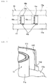
FIG. 2 (a) is an oblique view showing a fixed scroll used in the scroll compressor according to the present invention, andFIG. 2(b) is an oblique view showing a turning scroll used in a scroll compressor according to the present invention. -
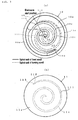
FIG. 3(a) is a view of the fixed scroll used in the scroll compressor according to the present invention seen from the spiral wall side (the spiral wall of the turning scroll is indicated by a virtual line), andFIG. 2(b) is a view of the turning scroll used in a scroll compressor according to the present invention seen from the end plate side (the spiral wall of the turning scroll is indicated by a dotted line). -
FIG. 4 is an explanatory diagram showing a relationship between the fixed scroll and the turning scroll. -
FIG. 5 is an oblique view showing a vicinity of the winding end section of the turning scroll. -
FIG. 6 is a view showing an example in which the inner wall surface of the extension section provided to the turning scroll is' caused to retract from the spiral wall of the fixed scroll opposed thereto. -
FIG. 7 is an enlarged oblique view showing a continuous contact section between the extension section and the end plate and spiral wall near the winding end section of the turning scroll. -
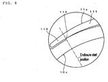
FIG. 8 is a view showing an example in which the outer wall face of the spiral wall of the fixed scroll opposed to the extension section provided to the turning scroll is made to retract. -
FIG. 9(a) is a view showing a conventional fixed scroll and turning scroll combined (the spiral wall of the turning scroll is indicated by a virtual line), andFIG. 9(b) is an enlarged plan view showing an area near the winding end section of the turning scroll. - An embodiment in a case where an electric compressor in which a compressor mechanism and an electric motor are integrated into a single unit is used as a scroll compressor according to the present invention is described below, with reference to the attached drawings.
-
FIG. 1 shows anelectric compressor 1 suited to a refrigeration cycle in which a refrigerant is used as a working fluid. In thiselectric compressor 1, anelectric motor 3 is disposed to the right in the drawing inside ahousing 2 that is made out of an aluminum alloy, and a compressor mechanism 4 that is driven by the electric motor is disposed to the left in the drawing. Note that inFIG. 1 the right side of the drawing is the front of the electric compressor and the left side of the drawing is the back of the electric compressor. - A
drive shaft 8 is provided in thehousing 2, rotatably supported viabearings front wall section 2a and a block member (shaft supporting member) 5 that is affixed in a generally central location inside thehousing 2. - A
motor containing space 31 that contains theelectric motor 3 is formed in thehousing 2 forward of theblock member 5, and astator 33 that constitutes theelectric motor 3 is contained herein. Thestator 33 is affixed to an inner surface of thehousing 2 and is made up of acore 34 that forms a cylindrical shape and acoil 35 that is wound therearound. Arotor 36 that comprises magnets rotatably contained inside thestator 33 is mounted on thedrive shaft 8, and therotor 36 rotates due to rotational magnetism formed by thestator 33. - The compressor mechanism 4 is a scroll type mechanism that has a
fixed scroll 10 and aturning scroll 11 that is disposed opposite thereto. As shown inFIGs. 2(a) ,3(a) , and4 , thefixed scroll 10 is constituted by a disk-shaped end plate 10a that is affixed to a rear section inside thehousing 2, a cylindrical outercircumferential wall 10d that is provided along an entire circumference of an outer edge of theend plate 10a and in an upright manner towards the front, and a spiral-shapedspiral wall 10c that is provided in an upright manner via acontinuous contact section 10b from theend plate 10a towards the front inside the outercircumferential wall 10d. - As shown in
FIGs. 2(b) ,3(b) , and4 , the turningscroll 11 is constituted by a disk-shaped end plate 11a and a spiral-shapedspiral wall 11c that is provided in an upright manner via acontinuous contact section 11b towards the rear from theend plate 11a. Aneccentric shaft 8 that is provided to a rear end section of thedrive shaft 8 and is eccentric relative to a center of thedrive shaft 8 is linked via abush 12 and abearing 13 to aboss section 11d that is formed on a back surface of theend plate 11a, and is supported in a manner that allows orbital motion around the center of thedrive shaft 8. - The
fixed scroll 10 and the turning scroll 11 mesh via thespiral walls spiral walls end plates compression chamber 15 is defined in a space enclosed by theend plate 10a and thespiral wall 10c of the fixedscroll 10 and theend plate 11a and thespiral wall 11c of the turningscroll 11. - A thin annular thrust race 16 is sandwiched between the
block member 5 and the outercircumferential wall 10d of the fixedscroll 10, the fixedscroll 10 and theblock member 5 abutting each other with the thrust race 16 interposed therebetween. - The thrust race 16 is formed from a material with outstanding wear resistance, is formed to a size having an outer edge shape that matches an outer edge shape of an end surface of the
block member 5, with a hole formed in a center through which theboss section 11d of the turningscroll 11 passes. The fixedscroll 10, the thrust race 16, and theblock member 5 are positioned and affixed by a positioning pin 9. - The
block member 5 is formed as a cylinder having an inner surface that grows in diameter in a stepped fashion towards the compressor mechanism 4, and aseal containing section 22 that contains aseal member 21 that seals theblock member 5 and thedrive shaft 8, abearing containing section 23 that contains thebearing 6, a weight containing section 24 that contains abalance weight 19 that rotates together with rotation of thedrive shaft 8 and forms a single unit with thebush 12, and an Oldham containing section 25 that contains anOldham ring 18 that serves as a rotation preventing mechanism disposed between the end face of theblock member 5 and theend plate 11a of the turningscroll 11 are formed, starting from the front side furthest from the thrust race 16. - Accordingly, the turning
scroll 11 produces rotational force due to rotation of thedrive shaft 8, but performs orbital motion relative to the center of thedrive shaft 8 because the rotation is limited by theOldham ring 18. - A
suction port 26 that suctions refrigerant introduced through asuction hole 40, which is discussed below, via amotor containing space 31 is formed on the outercircumferential wall 10d of the fixedscroll 10 described previously, and anejection chamber 28 into which a refrigerant gas which has been compressed in thecompression chamber 15 is ejected via anejection hole 27 formed substantially in a center of the fixedscroll 10 is defined between a rear of the fixedscroll 10 inside the housing and arear wall 2b of thehousing 2. The refrigerant gas that has been ejected into theejection chamber 28 is such that oil inside the gas is somewhat separated and is fed into an external refrigerant circuit through an ejection hole that is not shown in the drawings. The separated oil and the refrigerant with oil mixed in also collect in acollection chamber 32 provided below theejection chamber 28. - The
suction hole 40 that suctions the refrigerant gas is formed in a side surface of thehousing 2 facing themotor containing space 31, such that the refrigerant that has flowed from thesuction hole 40 into themotor containing space 31 via a gap between thestator 33 and thehousing 2, a pathway not shown in the drawings between theblock member 5 and thehousing 2, and a gap formed between the fixedscroll 10 and thehousing 2 is guided to thesuction port 26. -
Reference symbol 50 denotes an inverter containing chamber that contains an inverter drive circuit that is not shown in the drawings, which is formed in the top part of thehousing 2, and performs power supply control to theelectric motor 3, the inverter drive circuit and thestator 33 being electrically connected by way of a relay terminal that is not shown in the drawings such that power is supplied to theelectric motor 3 from the inverter drive circuit. - Accordingly, when the
electric motor 3 turns and thedrive shaft 8 turns, the turningscroll 11 turns around theeccentric shaft 8a in the compressor mechanism 4, and therefore the turningscroll 11 orbits around the center of the fixedscroll 10. When this happens, rotation of the turningscroll 11 is hindered by a rotation hindering mechanism comprising theOldham ring 18, and therefore only orbital motion is tolerated. - The orbital motion of the turning
scroll 11 causes thecompression chamber 15 to move from an outer circumferential side of thespiral walls compression chamber 15 from thesuction port 26 is compressed, and the refrigerant gas thus compressed is ejected into theejection chamber 28 via theejection hole 27 formed in theend plate 10a of the fixedscroll 10. The refrigerant gas is then fed to the external refrigerant circuit via an ejection port not shown in the drawings. - In this
electric compressor 1, thespiral wall 10c of the fixedscroll 10 and thespiral wall 11c of the turningscroll 11 are provided withcompression forming sections 101 and 111 for forming thecompression chamber 15, and windingend sections compression chamber 15, and, as shown inFIG. 5 , anextension section 113 that extends from the windingend section 112 is provided to thespiral wall 11c of the turningscroll 11. - The compression forming sections 101
ant 111 of thespiral walls end sections end sections spiral walls compression chamber 15 begins. - The
extension section 113 formed on the turningscroll 11 is provided extending out so as not to come into contact with thespiral wall 10c of the fixedscroll 10. Theextension section 113 does not come into contact with thespiral wall 10c of the fixedscroll 10 because, as shown in detail inFIG. 6 , an inner wall face of theextension section 113 is caused to retract from thespiral wall 10c of the fixedscroll 10 opposed thereto in this example, whether theextension section 113 is formed along the involute curve or not. - The
extension section 113 is set so as to have a height from the end plate 11a. that is lower than a height of thespiral wall 11c, and in this example, a transitional section from the windingend section 112 to theextension section 113 is formed so as to have a height from the end plate that gradually decreases. - The
extension section 113 is provided to a location opposite thesuction port 26 that is provided to the circumferential wall of the fixedscroll 10. A fluid to be compressed that was introduced through thesuction port 26 is guided to thecompression chamber 15 by passing through theextension section 113. - In the above configuration, the turning
scroll 11 orbits around the center of the fixedscroll 10, and when the windingend section 112 abuts thespiral wall 10c of the fixedscroll 10 the fluid to be compressed is enclosed in thecompression chamber 15 and compression of the fluid to be compressed thus enclosed begins. However, even if a contact load acts in an outward radial direction on the windingend section 112 when the windingend section 112 come into contact with thespiral wall 10c of the fixedscroll 10, theextension section 113 that does not come into contact with thespiral wall 10c of the fixedscroll 10 is provided to thespiral wall 11c of the turningscroll 11 from the windingend section 112, and therefore, as shown inFIG. 7 , the contact load, which acts so as to shear thespiral wall 11c from theend plate 11a is borne not only by thecontinuous contact section 111b in which thespiral wall 11c extending along thecompression forming section 111 is in continuous contact with theend plate 11a, but also thecontinuous contact section 113b in which theextension section 113 is in continuous contact with theend plate 11a. Therefore, sufficient area is ensured supporting this shear load near the windingend section 112, making it possible to reduce the shear stress near the windingend section 112 and prevent breakage of the spiral wall at the windingend section 112. - In the above configuration, because a non-contact state with the
spiral wall 10c of the fixedscroll 10 is formed by causing the inner wall face of theextension section 113 to retract from thespiral wall 10c of the fixedscroll 10 opposite thereto, there is no need to make thespiral wall 10c of the fixedscroll 10 thinner, making it possible to ensure strength of thespiral wall 10c of the fixedscroll 10. - The
extension section 113 is formed such that the transitional section from the windingend section 112 has a height that gradually decreases from theend plate 11a, and therefore deformation can be prevented by supporting thespiral wall 11c so as not to tip outward due to cutting resistance during machining, making it possible to minimize an increase in weight of the turningscroll 11 while ensuring contact area with theend plate 11a. - On machining the spiral walls of the scrolls with an end mill, when the tool is machining locations of the spiral walls to be machined, these machining locations are pushed on by the tool due to cutting resistance and are therefore vertical from the end plate, so as to follow the tool. However, after the tool has passed by, a phenomenon (known as "spring-back") whereby the spiral wall tilts inward is caused by elasticity of spiral wall itself which has been released from the cutting resistance. When machining locations other than the winding end sections, both sides of the machining location are supported by the
spiral wall 111, and therefore this phenomenon is so minor as to be negligible. However, when machining the windingend section 112 of a spiral wall having a conventional structure, thespiral wall 111 is only present on one side of the winding end section, and therefore the spiral wall deforms outwards in the radial direction due to the cutting resistance during machining, and then tends to tilt inwards after machining due to elasticity of the spiral wall itself. If the spiral walls come into contact with each other in these locations, there is a risk that the winding end section will break. - Accordingly, by making the height of the extension section from the end plate gradually lower starting from the winding end section, sufficient height of the extension section is ensured near the winding end, making it possible to prevent deformation by supporting the spiral wall that tends to tip outward due to the cutting resistance during machining. Moreover, locations far from the winding end section contribute little to an effect of preventing tilting of the winding end section due to the cutting resistance, and therefore it is possible to avoid an increase in the weight of the scroll by setting the height of the extension section, which does not need to be high, so as to be low.
- Because the height of the extension section from the end plate gradually decreases starting from the winding end section, it is possible to avoid an increase in suction resistance of the fluid to be compressed even if the
suction port 26 that guides the fluid to be compressed to thecompression chamber 15 is provided to the outercircumferential wall 10d of the fixedscroll 10 opposing theextension section 113, eliminating any drawbacks of providing theextension section 113. - In the above configuration, an example was given in which a non-contact state was formed by causing the inner wall face of the
extension section 113 to retract from thespiral wall 10c of the fixedscroll 10 opposed thereto, but, as shown inFIG. 8 , it is also possible to form a non-contact state by causing the outer wall face of thespiral wall 10c of the fixedscroll 10 opposing theextension section 113 to retract. - With this configuration, there is no need to make the
extension section 113 thinner, making it possible to ensure strength of theextension section 113. - Also, in the above configuration, an example was given of a configuration in which the
extension section 113 was formed from the windingend section 112 on thespiral wall 11c of the turningscroll 11, but it is also possible to form an extension section similarly on the windingend section 102 of thespiral wall 10c of the fixedscroll 10 instead of or together with this configuration. - Furthermore, in the above example, an example was given in which the configuration was adopted in a scroll-type electric compressor, but a similar configuration may also be adopted in a scroll compressor in which drive force is transmitted from outside.
-
- 1
- Electric compressor
- 8
- Drive shaft
- 10
- Fixed scroll
- 10a
- End plate
- 10c
- Spiral wall
- 11
- Turning scroll
- 11a
- End plate
- 11c
- Spiral wall
- 15
- Compression chamber
- 26
- Suction port
- 101, 111
- Compression forming section
- 102, 112
- Winding end section
- 113
- Extension section
Claims (6)
- A scroll compressor comprising a fixed scroll that has an end plate and a spiral wall that is provided upright from the end plate, a turning scroll that is disposed opposing the fixed scroll and has an end plate and a spiral wall that is provided upright from the end plate, and a drive shaft that transmits rotational force to the turning scroll, which scroll compressor compresses a fluid to be compressed by moving a compression chamber formed by the fixed scroll and the turning scroll towards a center while reducing a volume thereof through orbital motion of the turning scroll,
characterized in that an extension section is provided to the spiral wall of at least one of the fixed scroll or the turning scroll from the winding end section that is a terminal end of a wall face for forming the compression chamber, said extension section not coming into contact with the other spiral wall. - The scroll compressor as claimed in claim 1, characterized in that the extension section forms a non-contact state with the other spiral wall by causing an inner wall face thereof to retract from the other spiral wall opposed thereto.
- The scroll compressor as claimed in claim 1, characterized in that the extension section forms a non-contact state with the other spiral wall by causing an outer wall face of the other spiral wall opposed thereto to retract.
- The scroll compressor as claimed in any one of claims 1 to 3, characterized in that the extension section is set so as to have a height from the end plate that is lower than a height of the spiral wall.
- The scroll compressor as claimed in claim 4, characterized in that a transitional section from the winding end section to the extension section has a height that gradually decreases.
- The scroll compressor as claimed in claim 4 or 5, wherein the suction port that guides the fluid to be compressed into the compression chamber is provided to a circumferential wall of the fixed scroll opposing the extension section.
Applications Claiming Priority (2)
| Application Number | Priority Date | Filing Date | Title |
|---|---|---|---|
| JP2013111737A JP6267441B2 (en) | 2013-05-28 | 2013-05-28 | Scroll compressor |
| PCT/JP2014/063771 WO2014192666A1 (en) | 2013-05-28 | 2014-05-26 | Scroll compressor |
Publications (2)
| Publication Number | Publication Date |
|---|---|
| EP3018348A1 true EP3018348A1 (en) | 2016-05-11 |
| EP3018348A4 EP3018348A4 (en) | 2017-04-12 |
Family
ID=51988698
Family Applications (1)
| Application Number | Title | Priority Date | Filing Date |
|---|---|---|---|
| EP14803713.8A Withdrawn EP3018348A4 (en) | 2013-05-28 | 2014-05-26 | Scroll compressor |
Country Status (5)
| Country | Link |
|---|---|
| US (1) | US10060434B2 (en) |
| EP (1) | EP3018348A4 (en) |
| JP (1) | JP6267441B2 (en) |
| CN (1) | CN105247215B (en) |
| WO (1) | WO2014192666A1 (en) |
Families Citing this family (8)
| Publication number | Priority date | Publication date | Assignee | Title |
|---|---|---|---|---|
| KR102489482B1 (en) | 2016-04-26 | 2023-01-17 | 엘지전자 주식회사 | Scroll compressor |
| KR102487906B1 (en) * | 2016-04-26 | 2023-01-12 | 엘지전자 주식회사 | Scroll compressor |
| JP6947106B2 (en) | 2018-03-30 | 2021-10-13 | 株式会社豊田自動織機 | Scroll compressor |
| JP6956131B2 (en) | 2019-03-28 | 2021-10-27 | 株式会社豊田自動織機 | Scroll compressor |
| WO2021090423A1 (en) * | 2019-11-07 | 2021-05-14 | 三菱電機株式会社 | Scroll compressor and refrigeration cycle device |
| JP7517220B2 (en) | 2021-03-25 | 2024-07-17 | 株式会社豊田自動織機 | Electric Compressor |
| EP4513037A4 (en) * | 2022-04-20 | 2026-03-25 | Copeland Climate Tech Suzhou Co Ltd | SPIRAL COMPONENT OF A COMPRESSION MECHANISM, COMPRESSION MECHANISM AND SPIRAL COMPRESSOR |
| EP4467810A3 (en) * | 2024-07-15 | 2025-02-26 | Pfeiffer Vacuum Technology AG | Scroll vacuum pump and method for producing a scroll vacuum pump |
Family Cites Families (17)
| Publication number | Priority date | Publication date | Assignee | Title |
|---|---|---|---|---|
| JPS59142482U (en) * | 1983-03-15 | 1984-09-22 | サンデン株式会社 | Scroll type fluid device |
| ES2034944T3 (en) * | 1987-11-23 | 1993-10-01 | Copeland Corporation | HELICAL MACHINE. |
| US4927341A (en) | 1987-11-23 | 1990-05-22 | Copeland Corporation | Scroll machine with relieved flank surface |
| JP2616111B2 (en) * | 1990-03-12 | 1997-06-04 | ダイキン工業株式会社 | Scroll type fluid device |
| JP3105729B2 (en) * | 1994-02-04 | 2000-11-06 | 三菱重工業株式会社 | Scroll compressor |
| JPH0861268A (en) * | 1994-08-25 | 1996-03-08 | Mitsubishi Heavy Ind Ltd | Scroll type compressor |
| CN1082146C (en) * | 1995-08-31 | 2002-04-03 | 三菱重工业株式会社 | Eddy tube type fluid machinery |
| JP3539189B2 (en) * | 1998-03-10 | 2004-07-07 | 株式会社日立製作所 | Scroll fluid machine |
| JP2000249085A (en) * | 1999-03-01 | 2000-09-12 | Sanyo Electric Co Ltd | Scroll compressor |
| JP2001020878A (en) * | 1999-07-06 | 2001-01-23 | Fujitsu General Ltd | Scroll compressor |
| JP2001173584A (en) * | 1999-09-01 | 2001-06-26 | Matsushita Electric Ind Co Ltd | Scroll compressor |
| JP4191339B2 (en) * | 1999-10-26 | 2008-12-03 | 三菱重工業株式会社 | Scroll type fluid machinery |
| US20090185927A1 (en) * | 2008-01-17 | 2009-07-23 | Bitzer Scroll Inc. | Key Coupling and Scroll Compressor Incorporating Same |
| JP5034975B2 (en) * | 2008-01-24 | 2012-09-26 | パナソニック株式会社 | Scroll compressor |
| CN201428596Y (en) * | 2009-04-10 | 2010-03-24 | 川北科技(北京)有限公司 | Vortex dry vacuum pump |
| JP5428522B2 (en) * | 2009-05-22 | 2014-02-26 | パナソニック株式会社 | Scroll compressor |
| KR101059880B1 (en) * | 2011-03-09 | 2011-08-29 | 엘지전자 주식회사 | Scroll compressor |
-
2013
- 2013-05-28 JP JP2013111737A patent/JP6267441B2/en not_active Expired - Fee Related
-
2014
- 2014-05-26 CN CN201480030194.8A patent/CN105247215B/en not_active Expired - Fee Related
- 2014-05-26 US US14/892,597 patent/US10060434B2/en not_active Expired - Fee Related
- 2014-05-26 EP EP14803713.8A patent/EP3018348A4/en not_active Withdrawn
- 2014-05-26 WO PCT/JP2014/063771 patent/WO2014192666A1/en not_active Ceased
Non-Patent Citations (1)
| Title |
|---|
| See references of WO2014192666A1 * |
Also Published As
| Publication number | Publication date |
|---|---|
| US20160108915A1 (en) | 2016-04-21 |
| US10060434B2 (en) | 2018-08-28 |
| JP2014231750A (en) | 2014-12-11 |
| EP3018348A4 (en) | 2017-04-12 |
| CN105247215A (en) | 2016-01-13 |
| JP6267441B2 (en) | 2018-01-24 |
| WO2014192666A1 (en) | 2014-12-04 |
| CN105247215B (en) | 2018-05-08 |
Similar Documents
| Publication | Publication Date | Title |
|---|---|---|
| US10060434B2 (en) | Scroll compressor | |
| EP2390507A2 (en) | Shaft bearing clearances for an hermetic compressor. | |
| JP5888897B2 (en) | Scroll member and scroll type fluid machine | |
| US20080304994A1 (en) | Scroll Fluid Machine | |
| JP2012052527A (en) | Scroll type fluid machine | |
| JP2017166366A (en) | Scroll compressor | |
| JP2020153295A (en) | Scroll compressor | |
| JP6305552B2 (en) | Scroll compressor | |
| CN108350880A (en) | scroll compressor | |
| JP2014029117A (en) | Scroll compressor | |
| JP6328322B2 (en) | Compressor with slide bearing | |
| JP6607970B2 (en) | Scroll compressor | |
| US7273361B2 (en) | Coupling structure of eccentric bush of scroll compressor | |
| JP3124437B2 (en) | Scroll compressor | |
| JPWO2010097959A1 (en) | Scroll fluid machinery | |
| JP7395004B2 (en) | scroll compressor | |
| JPH0452399B2 (en) | ||
| JP5063638B2 (en) | Scroll compressor | |
| JP2017186948A (en) | Scroll compressor and air conditioner equipped with the same | |
| JP2016156297A (en) | Scroll compressor | |
| WO2016120982A1 (en) | Electrically driven compressor | |
| JP2001153072A (en) | Hermetic scroll compressor | |
| JP2000073970A (en) | Scroll compressor | |
| JP2013204476A (en) | Scroll compressor | |
| JP2016205153A (en) | Scroll compressor and Oldham coupling for scroll compressor |
Legal Events
| Date | Code | Title | Description |
|---|---|---|---|
| PUAI | Public reference made under article 153(3) epc to a published international application that has entered the european phase |
Free format text: ORIGINAL CODE: 0009012 |
|
| 17P | Request for examination filed |
Effective date: 20151202 |
|
| AK | Designated contracting states |
Kind code of ref document: A1 Designated state(s): AL AT BE BG CH CY CZ DE DK EE ES FI FR GB GR HR HU IE IS IT LI LT LU LV MC MK MT NL NO PL PT RO RS SE SI SK SM TR |
|
| AX | Request for extension of the european patent |
Extension state: BA ME |
|
| DAX | Request for extension of the european patent (deleted) | ||
| A4 | Supplementary search report drawn up and despatched |
Effective date: 20170315 |
|
| RIC1 | Information provided on ipc code assigned before grant |
Ipc: F04C 18/02 20060101AFI20170309BHEP |
|
| 17Q | First examination report despatched |
Effective date: 20200414 |
|
| STAA | Information on the status of an ep patent application or granted ep patent |
Free format text: STATUS: THE APPLICATION IS DEEMED TO BE WITHDRAWN |
|
| 18D | Application deemed to be withdrawn |
Effective date: 20200825 |