EP3018312A1 - Condensed water processing device for internal combustion engine - Google Patents
Condensed water processing device for internal combustion engine Download PDFInfo
- Publication number
- EP3018312A1 EP3018312A1 EP13888072.9A EP13888072A EP3018312A1 EP 3018312 A1 EP3018312 A1 EP 3018312A1 EP 13888072 A EP13888072 A EP 13888072A EP 3018312 A1 EP3018312 A1 EP 3018312A1
- Authority
- EP
- European Patent Office
- Prior art keywords
- condensed water
- additive
- supply
- combustion engine
- internal combustion
- Prior art date
- Legal status (The legal status is an assumption and is not a legal conclusion. Google has not performed a legal analysis and makes no representation as to the accuracy of the status listed.)
- Granted
Links
Images


Classifications
-
- F—MECHANICAL ENGINEERING; LIGHTING; HEATING; WEAPONS; BLASTING
- F02—COMBUSTION ENGINES; HOT-GAS OR COMBUSTION-PRODUCT ENGINE PLANTS
- F02M—SUPPLYING COMBUSTION ENGINES IN GENERAL WITH COMBUSTIBLE MIXTURES OR CONSTITUENTS THEREOF
- F02M26/00—Engine-pertinent apparatus for adding exhaust gases to combustion-air, main fuel or fuel-air mixture, e.g. by exhaust gas recirculation [EGR] systems
- F02M26/13—Arrangement or layout of EGR passages, e.g. in relation to specific engine parts or for incorporation of accessories
- F02M26/35—Arrangement or layout of EGR passages, e.g. in relation to specific engine parts or for incorporation of accessories with means for cleaning or treating the recirculated gases, e.g. catalysts, condensate traps, particle filters or heaters
-
- F—MECHANICAL ENGINEERING; LIGHTING; HEATING; WEAPONS; BLASTING
- F01—MACHINES OR ENGINES IN GENERAL; ENGINE PLANTS IN GENERAL; STEAM ENGINES
- F01N—GAS-FLOW SILENCERS OR EXHAUST APPARATUS FOR MACHINES OR ENGINES IN GENERAL; GAS-FLOW SILENCERS OR EXHAUST APPARATUS FOR INTERNAL-COMBUSTION ENGINES
- F01N3/00—Exhaust or silencing apparatus having means for purifying, rendering innocuous, or otherwise treating exhaust
- F01N3/005—Exhaust or silencing apparatus having means for purifying, rendering innocuous, or otherwise treating exhaust for draining or otherwise eliminating condensates or moisture accumulating in the apparatus
-
- F—MECHANICAL ENGINEERING; LIGHTING; HEATING; WEAPONS; BLASTING
- F01—MACHINES OR ENGINES IN GENERAL; ENGINE PLANTS IN GENERAL; STEAM ENGINES
- F01N—GAS-FLOW SILENCERS OR EXHAUST APPARATUS FOR MACHINES OR ENGINES IN GENERAL; GAS-FLOW SILENCERS OR EXHAUST APPARATUS FOR INTERNAL-COMBUSTION ENGINES
- F01N3/00—Exhaust or silencing apparatus having means for purifying, rendering innocuous, or otherwise treating exhaust
- F01N3/08—Exhaust or silencing apparatus having means for purifying, rendering innocuous, or otherwise treating exhaust for rendering innocuous
-
- F—MECHANICAL ENGINEERING; LIGHTING; HEATING; WEAPONS; BLASTING
- F01—MACHINES OR ENGINES IN GENERAL; ENGINE PLANTS IN GENERAL; STEAM ENGINES
- F01N—GAS-FLOW SILENCERS OR EXHAUST APPARATUS FOR MACHINES OR ENGINES IN GENERAL; GAS-FLOW SILENCERS OR EXHAUST APPARATUS FOR INTERNAL-COMBUSTION ENGINES
- F01N3/00—Exhaust or silencing apparatus having means for purifying, rendering innocuous, or otherwise treating exhaust
- F01N3/08—Exhaust or silencing apparatus having means for purifying, rendering innocuous, or otherwise treating exhaust for rendering innocuous
- F01N3/10—Exhaust or silencing apparatus having means for purifying, rendering innocuous, or otherwise treating exhaust for rendering innocuous by thermal or catalytic conversion of noxious components of exhaust
- F01N3/18—Exhaust or silencing apparatus having means for purifying, rendering innocuous, or otherwise treating exhaust for rendering innocuous by thermal or catalytic conversion of noxious components of exhaust characterised by methods of operation; Control
- F01N3/20—Exhaust or silencing apparatus having means for purifying, rendering innocuous, or otherwise treating exhaust for rendering innocuous by thermal or catalytic conversion of noxious components of exhaust characterised by methods of operation; Control specially adapted for catalytic conversion
- F01N3/206—Adding periodically or continuously substances to exhaust gases for promoting purification, e.g. catalytic material in liquid form, NOx reducing agents
- F01N3/2066—Selective catalytic reduction [SCR]
-
- F—MECHANICAL ENGINEERING; LIGHTING; HEATING; WEAPONS; BLASTING
- F01—MACHINES OR ENGINES IN GENERAL; ENGINE PLANTS IN GENERAL; STEAM ENGINES
- F01N—GAS-FLOW SILENCERS OR EXHAUST APPARATUS FOR MACHINES OR ENGINES IN GENERAL; GAS-FLOW SILENCERS OR EXHAUST APPARATUS FOR INTERNAL-COMBUSTION ENGINES
- F01N3/00—Exhaust or silencing apparatus having means for purifying, rendering innocuous, or otherwise treating exhaust
- F01N3/08—Exhaust or silencing apparatus having means for purifying, rendering innocuous, or otherwise treating exhaust for rendering innocuous
- F01N3/10—Exhaust or silencing apparatus having means for purifying, rendering innocuous, or otherwise treating exhaust for rendering innocuous by thermal or catalytic conversion of noxious components of exhaust
- F01N3/18—Exhaust or silencing apparatus having means for purifying, rendering innocuous, or otherwise treating exhaust for rendering innocuous by thermal or catalytic conversion of noxious components of exhaust characterised by methods of operation; Control
- F01N3/20—Exhaust or silencing apparatus having means for purifying, rendering innocuous, or otherwise treating exhaust for rendering innocuous by thermal or catalytic conversion of noxious components of exhaust characterised by methods of operation; Control specially adapted for catalytic conversion
- F01N3/206—Adding periodically or continuously substances to exhaust gases for promoting purification, e.g. catalytic material in liquid form, NOx reducing agents
- F01N3/208—Control of selective catalytic reduction [SCR], e.g. by adjusting the dosing of reducing agent
-
- F—MECHANICAL ENGINEERING; LIGHTING; HEATING; WEAPONS; BLASTING
- F02—COMBUSTION ENGINES; HOT-GAS OR COMBUSTION-PRODUCT ENGINE PLANTS
- F02D—CONTROLLING COMBUSTION ENGINES
- F02D41/00—Electrical control of supply of combustible mixture or its constituents
- F02D41/0025—Controlling engines characterised by use of non-liquid fuels, pluralities of fuels, or non-fuel substances added to the combustible mixtures
- F02D41/0047—Controlling exhaust gas recirculation [EGR]
-
- F—MECHANICAL ENGINEERING; LIGHTING; HEATING; WEAPONS; BLASTING
- F02—COMBUSTION ENGINES; HOT-GAS OR COMBUSTION-PRODUCT ENGINE PLANTS
- F02D—CONTROLLING COMBUSTION ENGINES
- F02D41/00—Electrical control of supply of combustible mixture or its constituents
- F02D41/02—Circuit arrangements for generating control signals
- F02D41/04—Introducing corrections for particular operating conditions
- F02D41/10—Introducing corrections for particular operating conditions for acceleration
- F02D41/107—Introducing corrections for particular operating conditions for acceleration and deceleration
-
- F—MECHANICAL ENGINEERING; LIGHTING; HEATING; WEAPONS; BLASTING
- F02—COMBUSTION ENGINES; HOT-GAS OR COMBUSTION-PRODUCT ENGINE PLANTS
- F02D—CONTROLLING COMBUSTION ENGINES
- F02D41/00—Electrical control of supply of combustible mixture or its constituents
- F02D41/24—Electrical control of supply of combustible mixture or its constituents characterised by the use of digital means
- F02D41/26—Electrical control of supply of combustible mixture or its constituents characterised by the use of digital means using computer, e.g. microprocessor
-
- F—MECHANICAL ENGINEERING; LIGHTING; HEATING; WEAPONS; BLASTING
- F02—COMBUSTION ENGINES; HOT-GAS OR COMBUSTION-PRODUCT ENGINE PLANTS
- F02M—SUPPLYING COMBUSTION ENGINES IN GENERAL WITH COMBUSTIBLE MIXTURES OR CONSTITUENTS THEREOF
- F02M25/00—Engine-pertinent apparatus for adding non-fuel substances or small quantities of secondary fuel to combustion-air, main fuel or fuel-air mixture
- F02M25/022—Adding fuel and water emulsion, water or steam
- F02M25/025—Adding water
- F02M25/028—Adding water into the charge intakes
-
- F—MECHANICAL ENGINEERING; LIGHTING; HEATING; WEAPONS; BLASTING
- F02—COMBUSTION ENGINES; HOT-GAS OR COMBUSTION-PRODUCT ENGINE PLANTS
- F02M—SUPPLYING COMBUSTION ENGINES IN GENERAL WITH COMBUSTIBLE MIXTURES OR CONSTITUENTS THEREOF
- F02M26/00—Engine-pertinent apparatus for adding exhaust gases to combustion-air, main fuel or fuel-air mixture, e.g. by exhaust gas recirculation [EGR] systems
-
- F—MECHANICAL ENGINEERING; LIGHTING; HEATING; WEAPONS; BLASTING
- F02—COMBUSTION ENGINES; HOT-GAS OR COMBUSTION-PRODUCT ENGINE PLANTS
- F02M—SUPPLYING COMBUSTION ENGINES IN GENERAL WITH COMBUSTIBLE MIXTURES OR CONSTITUENTS THEREOF
- F02M26/00—Engine-pertinent apparatus for adding exhaust gases to combustion-air, main fuel or fuel-air mixture, e.g. by exhaust gas recirculation [EGR] systems
- F02M26/02—EGR systems specially adapted for supercharged engines
- F02M26/04—EGR systems specially adapted for supercharged engines with a single turbocharger
- F02M26/06—Low pressure loops, i.e. wherein recirculated exhaust gas is taken out from the exhaust downstream of the turbocharger turbine and reintroduced into the intake system upstream of the compressor
-
- F—MECHANICAL ENGINEERING; LIGHTING; HEATING; WEAPONS; BLASTING
- F02—COMBUSTION ENGINES; HOT-GAS OR COMBUSTION-PRODUCT ENGINE PLANTS
- F02M—SUPPLYING COMBUSTION ENGINES IN GENERAL WITH COMBUSTIBLE MIXTURES OR CONSTITUENTS THEREOF
- F02M26/00—Engine-pertinent apparatus for adding exhaust gases to combustion-air, main fuel or fuel-air mixture, e.g. by exhaust gas recirculation [EGR] systems
- F02M26/13—Arrangement or layout of EGR passages, e.g. in relation to specific engine parts or for incorporation of accessories
- F02M26/14—Arrangement or layout of EGR passages, e.g. in relation to specific engine parts or for incorporation of accessories in relation to the exhaust system
- F02M26/15—Arrangement or layout of EGR passages, e.g. in relation to specific engine parts or for incorporation of accessories in relation to the exhaust system in relation to engine exhaust purifying apparatus
-
- F—MECHANICAL ENGINEERING; LIGHTING; HEATING; WEAPONS; BLASTING
- F02—COMBUSTION ENGINES; HOT-GAS OR COMBUSTION-PRODUCT ENGINE PLANTS
- F02M—SUPPLYING COMBUSTION ENGINES IN GENERAL WITH COMBUSTIBLE MIXTURES OR CONSTITUENTS THEREOF
- F02M26/00—Engine-pertinent apparatus for adding exhaust gases to combustion-air, main fuel or fuel-air mixture, e.g. by exhaust gas recirculation [EGR] systems
- F02M26/13—Arrangement or layout of EGR passages, e.g. in relation to specific engine parts or for incorporation of accessories
- F02M26/17—Arrangement or layout of EGR passages, e.g. in relation to specific engine parts or for incorporation of accessories in relation to the intake system
- F02M26/20—Feeding recirculated exhaust gases directly into the combustion chambers or into the intake runners
-
- F—MECHANICAL ENGINEERING; LIGHTING; HEATING; WEAPONS; BLASTING
- F02—COMBUSTION ENGINES; HOT-GAS OR COMBUSTION-PRODUCT ENGINE PLANTS
- F02M—SUPPLYING COMBUSTION ENGINES IN GENERAL WITH COMBUSTIBLE MIXTURES OR CONSTITUENTS THEREOF
- F02M26/00—Engine-pertinent apparatus for adding exhaust gases to combustion-air, main fuel or fuel-air mixture, e.g. by exhaust gas recirculation [EGR] systems
- F02M26/13—Arrangement or layout of EGR passages, e.g. in relation to specific engine parts or for incorporation of accessories
- F02M26/22—Arrangement or layout of EGR passages, e.g. in relation to specific engine parts or for incorporation of accessories with coolers in the recirculation passage
-
- F—MECHANICAL ENGINEERING; LIGHTING; HEATING; WEAPONS; BLASTING
- F01—MACHINES OR ENGINES IN GENERAL; ENGINE PLANTS IN GENERAL; STEAM ENGINES
- F01N—GAS-FLOW SILENCERS OR EXHAUST APPARATUS FOR MACHINES OR ENGINES IN GENERAL; GAS-FLOW SILENCERS OR EXHAUST APPARATUS FOR INTERNAL-COMBUSTION ENGINES
- F01N2610/00—Adding substances to exhaust gases
- F01N2610/02—Adding substances to exhaust gases the substance being ammonia or urea
-
- F—MECHANICAL ENGINEERING; LIGHTING; HEATING; WEAPONS; BLASTING
- F01—MACHINES OR ENGINES IN GENERAL; ENGINE PLANTS IN GENERAL; STEAM ENGINES
- F01N—GAS-FLOW SILENCERS OR EXHAUST APPARATUS FOR MACHINES OR ENGINES IN GENERAL; GAS-FLOW SILENCERS OR EXHAUST APPARATUS FOR INTERNAL-COMBUSTION ENGINES
- F01N2610/00—Adding substances to exhaust gases
- F01N2610/14—Arrangements for the supply of substances, e.g. conduits
- F01N2610/1453—Sprayers or atomisers; Arrangement thereof in the exhaust apparatus
- F01N2610/146—Control thereof, e.g. control of injectors or injection valves
-
- F—MECHANICAL ENGINEERING; LIGHTING; HEATING; WEAPONS; BLASTING
- F01—MACHINES OR ENGINES IN GENERAL; ENGINE PLANTS IN GENERAL; STEAM ENGINES
- F01N—GAS-FLOW SILENCERS OR EXHAUST APPARATUS FOR MACHINES OR ENGINES IN GENERAL; GAS-FLOW SILENCERS OR EXHAUST APPARATUS FOR INTERNAL-COMBUSTION ENGINES
- F01N2900/00—Details of electrical control or of the monitoring of the exhaust gas treating apparatus
- F01N2900/04—Methods of control or diagnosing
- F01N2900/0416—Methods of control or diagnosing using the state of a sensor, e.g. of an exhaust gas sensor
-
- F—MECHANICAL ENGINEERING; LIGHTING; HEATING; WEAPONS; BLASTING
- F02—COMBUSTION ENGINES; HOT-GAS OR COMBUSTION-PRODUCT ENGINE PLANTS
- F02B—INTERNAL-COMBUSTION PISTON ENGINES; COMBUSTION ENGINES IN GENERAL
- F02B37/00—Engines characterised by provision of pumps driven at least for part of the time by exhaust
-
- Y—GENERAL TAGGING OF NEW TECHNOLOGICAL DEVELOPMENTS; GENERAL TAGGING OF CROSS-SECTIONAL TECHNOLOGIES SPANNING OVER SEVERAL SECTIONS OF THE IPC; TECHNICAL SUBJECTS COVERED BY FORMER USPC CROSS-REFERENCE ART COLLECTIONS [XRACs] AND DIGESTS
- Y02—TECHNOLOGIES OR APPLICATIONS FOR MITIGATION OR ADAPTATION AGAINST CLIMATE CHANGE
- Y02T—CLIMATE CHANGE MITIGATION TECHNOLOGIES RELATED TO TRANSPORTATION
- Y02T10/00—Road transport of goods or passengers
- Y02T10/10—Internal combustion engine [ICE] based vehicles
- Y02T10/12—Improving ICE efficiencies
Definitions
- the present invention relates to a condensed water treatment device for an internal combustion engine, the condensed water treatment device treating condensed water generated in an EGR device.
- Patent Literature 1 As a condensed water treatment device for an internal combustion engine, known is the one which stores, in a condensed tank, condensed water generated in an EGR cooler, and injects the condensed water to an intake passage when the storage water quantity stored in the condensed water tank reaches a predetermined quantity (Patent Literature 1).
- the condensed water supplied to the intake passage is led into a cylinder with intake gas to vaporize. Thereby, the combustion temperature is suppressed. As a result of that, the generation quantity of NOx caused by combustion is suppressed.
- Patent Literature 2 As another literature of prior art relating to the present invention, there is a Patent Literature 2.
- Condensed water generated in an exhaust system of an internal combustion engine is acidity. Due to this, if a portion where the condensed water is supplied is metallic, there is a possibility that corrosion is generated at the supply portion of condensed water.
- the present invention aims to provide a condensed water treatment device for an internal combustion engine, the condensed water treatment device having ability to suppress corrosion of a supply portion of condensed water.
- a condensed water treatment device for an internal combustion engine as one aspect of the present invention is a condensed water treatment device for an internal combustion engine, the condensed water treatment device being applied to the internal combustion engine comprising: a selective-reduction type NOx catalyst which is provided on an exhaust passage and reduces NOx to purify exhaust gas by ammonia; an additive supplying valve which supplies additive which is ammonia or a precursor of ammonia to the exhaust passage at an upstream side of the NOx catalyst; and an EGR device which takes out the exhaust gas from the exhaust passage at a downstream side of the NOx catalyst and leads the exhaust gas taken to an intake system as EGR gas, wherein the condensed water treatment device comprises: a condensed water tank which stores condensed water generated in the EGR device; a condensed water supplying mechanism which supplies the condensed water stored in the condensed water tank to the internal combustion engine or a related device relating to the internal combustion engine; and an additive supply controlling device which is configured to increase, in a case where pH of the conden
- ammonia or an additive which is a precursor of ammonia is supplied to the exhaust passage at the upstream side of the selective-reduction type NOx catalyst, ammonia is held by the NOx catalyst and used for reducing NOx. On the other hand, ammonia which is not held by the NOx catalyst goes through the NOx catalyst.
- the EGR device takes out the exhaust gas at the downstream side of the NOx catalyst, the exhaust gas taken out by the EGR device includes ammonia which has passed through the NOx catalyst. Due to this, the ammonia dissolves in the condensed water generated in the EGR device. Accordingly, the pH of condensed water stored in the condensed water tank increases.
- the condensed water treatment device of the present invention in a case where the pH of condensed water stored in the condensed water tank is smaller than the threshold value, the supply quantity of the additive supplied to the exhaust passage is increased so that the supply quantity is larger than that of a case where the pH of condensed water stored in the condensed water tank is equal to or more than the threshold value.
- the additive supply controlling device may be configured to make the supply quantity of the additive smaller, as temperature of the NOx catalyst is higher. As the temperature of the NOx catalyst is higher, the quantity of ammonia which is held by the NOx catalyst becomes lower. According to this embodiment, as the temperature of the NOx catalyst is higher, less quantity of the additive is supplied. Thereby, it is possible to avoid a state that excessive quantity of ammonia goes through the NOx catalyst in time of high temperature. Thereby, it is possible to suppress an excessive increase of the pH of condensed water stored in the condensed water tank.
- the additive supply controlling device may be configured to execute decrease offset of supply quantity of the additive in a decreasing quantity period following after acceleration of the internal combustion engine ends.
- the acceleration of the internal combustion engine is executed, the temperature of the NOx catalyst increases whereby the holding quantity of ammonia decreases.
- the decrease offset is executed within the decreasing quantity period following after the acceleration ends. Thereby, it is possible to avoid a state that excessive quantity of ammonia goes through the NOx catalyst after the acceleration ends. Thereby, it is possible to suppress an excessive increase of the pH of condensed water stored in the condensed water tank.
- the additive supply controlling device may be configured to execute increase offset of supply quantity of the additive in an increasing quantity period following after deceleration of the internal combustion engine ends.
- the increase offset is executed within the increasing quantity period following after the deceleration ends.
- One embodiment of the condensed water treatment device of the present invention may further comprise: an additive holding portion which is connected with the additive supplying valve and holds the additive; an additive supply inhibiting device which is configured to inhibit the supply of the additive, in a case where a holding quantity of the additive in the additive holding portion is equal to or less than a predetermined value; and a condensed water generating device which is configured to, in a case where the additive supply inhibiting device inhibits the supply of the additive and also the pH of condensed water stored in the condensed water tank is smaller than the threshold value, increase an inflow quantity of the EGR gas which is led to the intake system in time of such an operating state that pH of condensed water generated in the EGR device is larger than the pH of condensed water stored in the condensed water tank.
- the holding quantity of the additive in a case where the holding quantity of the additive is equal to or less than the predetermined value, that is, the holding quantity is lacking, the supply of the additive is inhibited. Therefore, it is possible to avoid drawdown of the additive. Even in a case where the supply of additive is inhibited, in time of such an operating state that the pH of condensed water generated in the EGR device is larger than the pH of condensed water stored in the condensed water tank, the inflow quantity of EGR gas led to the intake system is increased. The inflow quantity of EGR gas is increased in such an operating state whereby it is promoted to generate condensed water showing pH larger than the pH of condensed water stored in the condensed water tank.
- the condensed water stored in the condensed water tank is attenuated by the condensed water generated by the increase of the EGR quantity.
- the holding quantity of the additive is lacking, it is possible to reduce the acidity of the condensed water stored in the condensed water tank.
- the supply of condensed water to the internal combustion engine includes the supply of condensed water to various related devices mounted to the internal combustion engine, as well as the supply of condensed water to the intake system or the exhaust system in the internal combustion engine. Further, the supply of condensed water to the related device means the supply of condensed water to each of various devices which relates to the internal combustion engine but does not relate directly to combustion of the internal combustion engine.
- an internal combustion engine 1 is configured as a four-cylinder type in line diesel engine in which four cylinders 2 are arranged along a straight line.
- the internal combustion engine 1 is mounted as a drive source for traveling of, for example, a car.
- the internal combustion engine 1 is provided, for each cylinder 2, with a fuel injection valve 3 for supplying fuel into each cylinder 2.
- Each fuel injection valve 3 is connected with a common rail 5 where fuel is forcibly fed, and fuel is supplied to each fuel injection valve 3 via the common rail 5.
- An intake passage 10 and an exhaust passage 11 are connected with each cylinder 2. Air led into the intake passage 10 is filled in each cylinder 2 at a suction stroke.
- Fuel injected from the fuel injection valve 3 to the cylinder 2 is self-ignited and combusted at a compression stroke. Exhaust gas after the combustion is led into the exhaust passage 11. The exhaust gas led to the exhaust passage 11 is drained to the atmospheric air after NOx is reduced by a selective-reduction type NOx catalyst 12. At the upstream side of the NOx catalyst 12, a turbine 15a of a turbo charger 15 is provided.
- the intake passage 10 is provided with a compressor 15b of the turbo charger 15, an intercooler 16 cooling air pressured by the compressor 15b, and a throttle valve 17 adjusting the flow rate of intake gas.
- the internal combustion engine 1 is provided with an additive supplying device 18 for supplying urea water, which is a precursor of ammonia, as an additive to the NOx catalyst 12.
- the additive supplying device 18 comprises: an additive supplying valve 18a which supplies urea water to the exhaust passage 11 at the upstream side of the NOx catalyst 12; a urea water tank 18b as an additive holding portion which stores urea water; a supplying passage 18c which connects the additive supplying valve 18a and the urea water tank 18b; and an electric pump 18d which pressures urea water in the supplying passage 18c. It is possible to control the supply quantity of urea water by controlling a valve opening period of the additive supplying valve 18a.
- the urea water tank 18b is provided with a water level sensor 18e which outputs a signal according to the storage water quantity (the water level) of urea water.
- a water level sensor 18e which outputs a signal according to the storage water quantity (the water level) of urea water.
- the internal combustion engine 1 is provided with an EGR device 20 which executes the EGR (Exhaust Gas Recirculation) that a part of exhaust gas is recirculated to an intake system for reduction of NOx and improvement of fuel economy.
- the EGR device 20 comprises: an EGR passage 21 connecting the exhaust passage 11 and the intake passage 10; an EGR cooler 22 cooling the exhaust gas in the EGR passage 21; and an EGR valve 23 for adjusting the flow rate of exhaust gas to be led to the intake passage 10 (the EGR gas).
- the EGR passage 21 has an exhaust side end portion opening at the downstream side of the NOx catalyst 12 and an intake side end portion opening at the upstream side of the compressor 15b.
- the EGR cooler 22 uses cooling water in the internal combustion engine 1 as a refrigerant, and decreases the temperature of the EGR gas by heat exchange between the refrigerant and warm exhaust gas.
- the temperature of the EGR gas decreases whereby moisture included in the EGR gas is condensed. Due to this, condensed water is generated in the EGR cooler 22.
- the temperature of the EGR gas in the EGR passage 21 decreases whereby condensed water is also generated in the EGR passage 21.
- the internal combustion engine 1 is provided with a condensed water treatment device 30 for collecting condensed water generated in the EGR cooler 22 and the EGR passage 21.
- the condensed water treatment device 30 comprises: a condensed water tank 31 which stores condensed water CW; and a condensed water supplying mechanism 32 which supplies to the intake system of the internal combustion engine 1, the condensed water CW stored in the condensed water tank 31.
- the condensed water tank 31 is provided with a pH sensor 34 which outputs a signal according to the pH of the condensed water CW stored.
- the condensed water supplying mechanism 32 has a condensed water passage 35 connecting the condensed water tank 31 and the intake passage 10.
- the condensed water passage 35 is provided with an electric pump 36 and an injection valve 37 which injects and supplies to the inside of the intake passage 10, the condensed water pressured by the pump 36. It is possible to control the supply quantity of condensed water by controlling a valve opening period of the injection valve 37.
- the internal combustion engine 1 is provided with an engine control unit (ECU) 40 configured as a computer which controls each portion of the internal combustion engine 1.
- the ECU 40 executes a main motion control for controlling the fuel injection quantity and the injection timing of the internal combustion engine 1 by operating the fuel injection valve 3.
- the ECU 40 is also used to control of the EGR device 20 and the condensed water treatment device 30. Further, the ECU 40 operates the additive supplying valve 18a so that a state that ammonia is held by the NOx catalyst 12 is kept, whereby the ECU 40 executes continuously the supply of urea water except a special condition. A part of ammonia generated by the supply of urea water is not held by the NOx catalyst 12, but goes through the NOx catalyst 12 and dissolves in condensed water.
- the pH of condensed water CW stored in the condensed water tank 31 increases. Details will be described later, but the ECU 40 controls the pH of the condensed water CW in the condensed water tank 31 by changing the supply quantity of urea water on purpose to make the quantity of ammonia going through the NOx catalyst 12 change.
- Signals from a lot of sensors are inputted to the ECU 40, the sensors detecting various kinds of physical amounts for grasping the operating state of the internal combustion engine 1.
- sensors relating to the present invention provided to the internal combustion engine 1 are a crank angle sensor 41 which outputs a signal according to a crank angle of the internal combustion engine 1, an accelerator opening degree sensor 42 which outputs a signal according to a depression amount of an accelerator pedal 50 provided to the internal combustion engine 1 (the accelerator opening degree), and the like.
- the signals outputted from those sensors are inputted to the ECU 40.
- the signals outputted from the water level sensor 18e, the temperature sensor 19, and the pH sensor 34 are also inputted to the ECU 40 respectively.
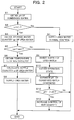
- a computer program of a control routine shown in fig.2 is stored in the ECU 40, and read out as appropriate and executed at predetermined intervals repeatedly.
- the ECU 40 obtains the pH of condensed water CW stored in the condensed water tank 31, based on the signal outputted by the pH sensor 34.
- the ECU 40 determines whether the pH obtained in step S1 is smaller than a threshold value t or not. Set as this threshold value t is 4. In a case where the pH of condensed water is smaller than the threshold value t, it is determined that the condensed water stored in the condensed water tank 31 has strong acidity. In a case where the pH is smaller than the threshold value t, the ECU 40 goes to step S3.
- step S4 the ECU 40 executes a normal control above mentioned, where the ECU 40 supplies a predetermined supply quantity of urea water to the exhaust passage 11 to maintain the holding quantity of ammonia in the NOx catalyst 12.
- step S3 the ECU 40 refers to the signal outputted by the water level sensor 18e and obtains the storage water quantity qw of urea water stored in the urea water tank 18b.
- the ECU 40 goes to step S6.
- the ECU 40 goes to step S9.
- the predetermined value qwt is set as a value for determining whether urea water is insufficient or not.
- the storage water quantity qw is more than the predetermined value qwt, this means that there is much quantity of urea water and the storage water quantity qw is sufficient.
- the storage water quantity qw is equal to or less than the predetermined value qwt, this means that there is not much quantity of urea water and the storage water quantity qw is insufficient.
- step S6 the ECU 40 obtains the temperature Tc of the NOx catalyst 12 by referring to the signal outputted by the temperature sensor 19.
- step S7 the ECU 40 calculates the supply quantity q of urea water.
- the supply quantity q calculated in this process is larger than the supply quantity of urea water in the normal control mentioned above.
- the supply quantity q is calculated so as to become larger as the pH of condensed water stored in the condensed water tank 31, which has been obtained in step S1, is smaller.
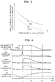
- the holding quantity Qa1 of ammonia held by the NOx catalyst 12 becomes smaller as the temperature Tc of the NOx catalyst 12 is higher. That is, as the temperature Tc of the NOx catalyst 12 is higher, the rate of ammonia which, not held by the NOx catalyst 12, goes through the NOx catalyst 12 becomes larger. Then, in order to suppress that the going-through quantity Qa2 of ammonia which goes through the NOx catalyst 12 increases excessively in time of high temperature, the ECU 40 calculates the supply quantity q of urea water so as to become smaller as the temperature Tc of the NOx catalyst 12 is higher, as shown by a solid line.
- the supply quantity q of urea water is calculated by, for example, the following method. That is, a calculation map (not illustrated) where the mentioned characteristics are reflected is stored in the ECU 40 beforehand, the calculation map giving the supply quantity q using the pH of condensed water and the temperature Tc of the NOx catalyst 12 as variables. And then, the ECU 40 refers to this calculation map and specifies the supply quantity q corresponding to the pH obtained in step S1 and the temperature Tc obtained in step S6. Thereby, the supply quantity q is calculated in consideration of: the pH of condensed water stored in the condensed water tank 31; and the temperature Tc of the NOx catalyst 12.
- step S8 the ECU 40 operates the additive supplying valve 18a so that the urea water having the supply quantity calculated in step S7 is supplied to the exhaust passage 11. Thereby, appropriate quantity of ammonia goes through the NOx catalyst 12 and dissolves in the condensed water. Due to this, the pH of condensed water stored in the condensed tank 31 increases whereby the acidity of condensed water is reduced.
- the ECU 40 functions as an additive supply controlling device according to the present invention, by executing the steps S1 to S8.
- step S9 the ECU 40 inhibits the supply of urea water to the exhaust passage 11 in consideration that the storage water quantity qw of the urea water tank 18b is insufficient. Thereby, the ECU 40 functions as an additive supply inhibiting device of the present invention.
- step S10 the ECU 40 obtains an engine rotational speed and a load as the operating state of the internal combustion engine 1. The engine rotational speed is obtained based on the signal outputted by the crank angle sensor 41, and the load is obtained based on the signal outputted by the accelerator opening sensor 42.
- step S11 the ECU 40 estimates density of NOx in exhaust gas based on the engine rotational speed and the load which have been obtained in step S10, and estimates pH' of condensed water generated in the EGR device 20, based on the density of NOx.
- step S12 the ECU 40 determines whether the pH' of condensed water generated in the EGR device 20 is larger than the pH of condensed water stored in the condensed water tank 31 or not. In a case where the pH' of condensed water generated in the EGR device 20 is larger than the pH of condensed water stored in the condensed water tank 31, the ECU 40 goes to step S13, and otherwise, the ECU 40 skips step S13 and ends the routine of this time.
- step S13 the ECU 40 executes an increase control of EGR quantity. This increase control is a control for promoting the generation of condensed water by increasing the EGR quantity so as to be larger than the EGR quantity determined based on the operating state of the internal combustion engine 1.
- the ECU 40 functions as a condensed water generating device of the present invention by executing step S13.
- the increase control of EGR quantity will be further explained in reference to fig.4 .
- the EGR quantity shown in fig.4 corresponds to an instruction value of the opening degree the ECU 40 gives the EGR valve 23, and does not indicate quantity of EGR gas actually led into the intake system.
- the combustion temperature decreases due to the increase of EGR quantity
- the NOx generation quantity which has increased temporally turns to decline, and comes back to the almost same quantity as the NOx generation quantity showed before the increase of EGR quantity.
- the EGR quantity is increased at the time t1 and the EGR quantity increased is maintained until time t2 whereby the generation quantity of condensed water increases. Accordingly, the condensed water stored in the condensed water tank 31 is attenuated. Therefore, the pH of the condensed water increases, that is, the acidity is reduced.
- the ECU 40 maintains the opening degree of the EGR valve 23 for the increase of EGR quantity and starts to reduce gradually the opening degree from the time t2 to reduce gradually the EGR quantity. Thereby, the smoke generation quantity and the fuel consumption rate decreases gradually. Therefore, it is possible to suppress deterioration of the smoke generation quantity and the fuel consumption rate because of a quick decrease of the EGR quantity.
- the opening degree of the EGR valve 23 returns at time t3 to the opening degree showed before the increase of EGR quantity, the smoke generation quantity and the fuel consumption rate return to the ones showed before the increase of EGR quantity as well. Thereby, the pH of the condensed water stored in the condensed water tank 31 becomes an equilibrium state.
- the first embodiment in a case where the pH of condensed water stored in the condensed water tank 31 is smaller than the threshold value t, ammonia the quantity of which is larger than the quantity of a case where the pH is equal to or more than the threshold value t, goes through the NOx catalyst 12 and dissolves in the condensed water. Therefore, as the acidity of condensed water stored in the condensed water tank 31 is higher, the acidity of condensed water is more reduced by ammonia which has passed through the NOx catalyst 12. As a result of that, it is possible to avoid an excessive reduction of the pH of condensed water stored in the condensed water tank 31. Accordingly, it is possible to suppress corrosion of each part of the internal combustion engine 1, to which the condensed water is supplied.
- the storage water quantity qw of the urea water tank 18b is insufficient, the supply of urea water is inhibited. Therefore, it is possible to avoid drawdown of the urea water. Even in a case where the supply of urea water is inhibited, in time of such an operating state that the pH' of condensed water generated in the EGR device 20 is larger than the pH of condensed water stored in the condensed water tank 31, the EGR quantity is increased. By the condensed water generated because of the increase of the EGR quantity, condensed water stored in the condensed water tank 31 is attenuated.
- the second embodiment is characterized by control in transition time of acceleration and can be executed along with the control of the first embodiment. Since the physical configuration of the second embodiment is the same as the one of the first embodiment, fig.1 is referenced with respect to the physical configuration of the second embodiment.
- the temperature of the NOx catalyst 12 increases rapidly along with increase of the exhaust gas temperature.
- the holding quantity of ammonia of the NOx catalyst 12 becomes lower as the temperature is higher. Therefore, in a state that the temperature of the NOx catalyst 12 increases rapidly because of rapid acceleration, if the supply quantity of urea water is calculated in a similar way to that in normal time of the first embodiment, there is a possibility that ammonia goes through the NOx catalyst 12 excessively whereby the pH of condensed water stored in the condensed water tank 31 excessively increase. Then, in the second embodiment, a decrease offset of the supply quantity of urea water is executed during a certain period following rapid acceleration.
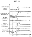
- Fig.5 shows temporal alternation shown by various parameters when the ECU 40 executes the control of the second embodiment along with the control of the first embodiment.
- the holding quantity of ammonia decreases along with a quick increase of the temperature of the NOx catalyst 12.
- This threshold value is set for determining whether the quick acceleration affects the increase of temperature of the NOx catalyst 12.
- the ECU 40 determines that the internal combustion engine 1 quickly accelerated at time t22, and executes the decrease offset of the supply quantity of urea water in a decreasing quantity period Td following after the acceleration ends. Thereby, it is possible to maintain the pH of the condensed water stored in the condensed water tank 31 in a neutral state.
- the length of the decreasing quantity period Td and the offset quantity may be determined as appropriate. Each of the length of the decreasing quantity period Td and the offset quantity may be a certain value, or be changed according to the temperature of the NOx catalyst 12.
- the decrease offset is executed in the decreasing quantity period Td following after the acceleration ends whereby it is possible to suppress that the pH of condensed water stored in the condensed water tank 31 increases excessively as shown by a broken line in fig.5 .
- the ECU 40 functions as the additive supply controlling device of the present invention by executing the control shown in fig.5 .
- the third embodiment is characterized by control in transition time of deceleration and can be executed along with the control of the first embodiment. Further, the third embodiment can be also executed with the second embodiment, along with the first embodiment. Since the physical configuration of the third embodiment is the same as the one of the first embodiment, fig.1 is referenced with respect to the physical configuration of the third embodiment.
- Fig.6 shows temporal alternation shown by various parameters when the ECU 40 executes the control of the third embodiment along with the control of the first embodiment.
- the temperature of the NOx catalyst 12 decreases whereby the holding quantity of ammonia increases.
- This threshold value is set for determining whether the rapid deceleration affects the decrease of temperature of the NOx catalyst 12.
- the ECU 40 determines that the internal combustion engine 1 rapidly decelerated at time t32, and executes the increase offset of the supply quantity of urea water in an increasing quantity period Ti following after the deceleration ends. Thereby, it is possible to suppress decrease of the quantity of ammonia which dissolves in condensed water.
- the length of the increasing quantity period Ti and the offset quantity may be determined as appropriate. Each of the length of the increasing quantity period Ti and the offset quantity may be a certain value, or be changed according to the temperature of the NOx catalyst 12.
- the increase offset is executed in the increasing quantity period Ti following after the deceleration ends whereby it is possible to suppress that the quantity of ammonia which goes through the NOx catalyst 12 decreases after the deceleration ends.
- the ECU 40 functions as the additive supply controlling device of the present invention by executing the control shown in fig.6 .
- condensed water is supplied to the intake passage 10 of the internal combustion engine 1.
- a portion which the condensed water is supplied to is not limited to the intake system of the internal combustion engine.
- the condensed water is supplied to the exhaust system, and by using a method similar to the internal EGR, the condensed water is led to a cylinder within a valve overlap period.
- condensed water is supplied to various kinds of devices mounted to an internal combustion engine.
- condensed water is supplied to various kinds of devices, such as an inter cooler which cools air pressured by a turbo charger and an accumulator which is used for heating lubricant oil or intake gas in an internal combustion engine.
- a related device relating to an internal combustion engine For example, it is possible to execute the present invention in such an embodiment that condensed water is supplied to various kinds of devices such as a drive device to which torque outputted by an internal combustion engine is transmitted and an air-conditioning device using heat generated in an internal combustion engine. In a case where condensed water is supplied to such devices, it is possible to suppress corrosion of portions to which condensed water is supplied.
- the supply quantity of urea water is calculated based on the pH of condensed water and the temperature of the NOx catalyst.
- the internal combustion engine 1 is configured as a diesel engine.
- an engine which the present invention can be applied to is not limited to a diesel engine.
- the present invention can be applied to a spark ignition type combustion engine.
- the present invention can be applied to a natural-intake-type internal combustion engine.
- condensed water can be supplied to an intake system by using negative pressure in an intake passage, it is possible to omit a pump for pressuring condensed water, the pump being provided in each above embodiment.
- urea water which is a precursor of ammonia is supplied to the NOx catalyst.
- ammonia in a state of a gaseous body or a liquid body is supplied to the NOx catalyst as an additive.
Landscapes
- Engineering & Computer Science (AREA)
- Chemical & Material Sciences (AREA)
- Combustion & Propulsion (AREA)
- Mechanical Engineering (AREA)
- General Engineering & Computer Science (AREA)
- Chemical Kinetics & Catalysis (AREA)
- Toxicology (AREA)
- Health & Medical Sciences (AREA)
- Microelectronics & Electronic Packaging (AREA)
- Computer Hardware Design (AREA)
- Exhaust Gas After Treatment (AREA)
- Exhaust Silencers (AREA)
- Output Control And Ontrol Of Special Type Engine (AREA)
Abstract
Description
- The present invention relates to a condensed water treatment device for an internal combustion engine, the condensed water treatment device treating condensed water generated in an EGR device.
- As a condensed water treatment device for an internal combustion engine, known is the one which stores, in a condensed tank, condensed water generated in an EGR cooler, and injects the condensed water to an intake passage when the storage water quantity stored in the condensed water tank reaches a predetermined quantity (Patent Literature 1). The condensed water supplied to the intake passage is led into a cylinder with intake gas to vaporize. Thereby, the combustion temperature is suppressed. As a result of that, the generation quantity of NOx caused by combustion is suppressed. In addition, as another literature of prior art relating to the present invention, there is a
Patent Literature 2. -
- PTL1:
JP-A- H10-318049 - PTL2:
JP-A-2010-43585 - Condensed water generated in an exhaust system of an internal combustion engine is acidity. Due to this, if a portion where the condensed water is supplied is metallic, there is a possibility that corrosion is generated at the supply portion of condensed water.
- Then, the present invention aims to provide a condensed water treatment device for an internal combustion engine, the condensed water treatment device having ability to suppress corrosion of a supply portion of condensed water.
- A condensed water treatment device for an internal combustion engine as one aspect of the present invention is a condensed water treatment device for an internal combustion engine, the condensed water treatment device being applied to the internal combustion engine comprising: a selective-reduction type NOx catalyst which is provided on an exhaust passage and reduces NOx to purify exhaust gas by ammonia; an additive supplying valve which supplies additive which is ammonia or a precursor of ammonia to the exhaust passage at an upstream side of the NOx catalyst; and an EGR device which takes out the exhaust gas from the exhaust passage at a downstream side of the NOx catalyst and leads the exhaust gas taken to an intake system as EGR gas, wherein the condensed water treatment device comprises: a condensed water tank which stores condensed water generated in the EGR device; a condensed water supplying mechanism which supplies the condensed water stored in the condensed water tank to the internal combustion engine or a related device relating to the internal combustion engine; and an additive supply controlling device which is configured to increase, in a case where pH of the condensed water stored in the condensed water tank is smaller than a threshold value, a supply quantity of the additive supplied to the exhaust passage so that the supply quantity is larger than the supply quantity of a case where the pH of the condensed water stored in the condensed water tank is equal to or more than the threshold value.
- In a case where ammonia or an additive which is a precursor of ammonia is supplied to the exhaust passage at the upstream side of the selective-reduction type NOx catalyst, ammonia is held by the NOx catalyst and used for reducing NOx. On the other hand, ammonia which is not held by the NOx catalyst goes through the NOx catalyst. In a case where the EGR device takes out the exhaust gas at the downstream side of the NOx catalyst, the exhaust gas taken out by the EGR device includes ammonia which has passed through the NOx catalyst. Due to this, the ammonia dissolves in the condensed water generated in the EGR device. Accordingly, the pH of condensed water stored in the condensed water tank increases.
- According to the condensed water treatment device of the present invention, in a case where the pH of condensed water stored in the condensed water tank is smaller than the threshold value, the supply quantity of the additive supplied to the exhaust passage is increased so that the supply quantity is larger than that of a case where the pH of condensed water stored in the condensed water tank is equal to or more than the threshold value. Thereby, in a case where the pH of condensed water stored in the condensed water tank is smaller than the threshold value, larger quantity of ammonia goes through the NOx catalyst and dissolves in the condensed water in comparison to a case where the pH is equal to or more than the threshold value. Due to this, as the acidity of condensed water stored in the condensed water tank is higher, the acidity of condensed water is more reduced by ammonia which has passed through the NOx catalyst. As a result of that, it is possible to avoid an excessive reduction of the pH of condensed water stored in the condensed water tank. Accordingly, it is possible to suppress corrosion of a supplied portion of the internal combustion engine or the related device to which the condensed water is supplied.
- As one embodiment of the condensed water treatment device of the present invention, the additive supply controlling device may be configured to make the supply quantity of the additive smaller, as temperature of the NOx catalyst is higher. As the temperature of the NOx catalyst is higher, the quantity of ammonia which is held by the NOx catalyst becomes lower. According to this embodiment, as the temperature of the NOx catalyst is higher, less quantity of the additive is supplied. Thereby, it is possible to avoid a state that excessive quantity of ammonia goes through the NOx catalyst in time of high temperature. Thereby, it is possible to suppress an excessive increase of the pH of condensed water stored in the condensed water tank.
- As one embodiment of the condensed water treatment device of the present invention, the additive supply controlling device may be configured to execute decrease offset of supply quantity of the additive in a decreasing quantity period following after acceleration of the internal combustion engine ends. In a case the acceleration of the internal combustion engine is executed, the temperature of the NOx catalyst increases whereby the holding quantity of ammonia decreases. According to this embodiment, with respect to the supply quantity of the additive, the decrease offset is executed within the decreasing quantity period following after the acceleration ends. Thereby, it is possible to avoid a state that excessive quantity of ammonia goes through the NOx catalyst after the acceleration ends. Thereby, it is possible to suppress an excessive increase of the pH of condensed water stored in the condensed water tank.
- As one embodiment of the condensed water treatment device of the present invention, the additive supply controlling device may be configured to execute increase offset of supply quantity of the additive in an increasing quantity period following after deceleration of the internal combustion engine ends. In a case the deceleration of the internal combustion engine is executed, the temperature of the NOx catalyst decreases whereby the holding quantity of ammonia increases. According to this embodiment, with respect to the supply quantity of the additive, the increase offset is executed within the increasing quantity period following after the deceleration ends. Thereby, it is possible to suppress that the quantity of ammonia which goes through the NOx catalyst decreases after the deceleration ends. Thereby, it is possible to suppress that the increase of pH of condensed water stored in the condensed water tank is delayed because of the deceleration of the internal combustion engine.
- One embodiment of the condensed water treatment device of the present invention may further comprise: an additive holding portion which is connected with the additive supplying valve and holds the additive; an additive supply inhibiting device which is configured to inhibit the supply of the additive, in a case where a holding quantity of the additive in the additive holding portion is equal to or less than a predetermined value; and a condensed water generating device which is configured to, in a case where the additive supply inhibiting device inhibits the supply of the additive and also the pH of condensed water stored in the condensed water tank is smaller than the threshold value, increase an inflow quantity of the EGR gas which is led to the intake system in time of such an operating state that pH of condensed water generated in the EGR device is larger than the pH of condensed water stored in the condensed water tank.
- According to this embodiment, in a case where the holding quantity of the additive is equal to or less than the predetermined value, that is, the holding quantity is lacking, the supply of the additive is inhibited. Therefore, it is possible to avoid drawdown of the additive. Even in a case where the supply of additive is inhibited, in time of such an operating state that the pH of condensed water generated in the EGR device is larger than the pH of condensed water stored in the condensed water tank, the inflow quantity of EGR gas led to the intake system is increased. The inflow quantity of EGR gas is increased in such an operating state whereby it is promoted to generate condensed water showing pH larger than the pH of condensed water stored in the condensed water tank. Thereby, the condensed water stored in the condensed water tank is attenuated by the condensed water generated by the increase of the EGR quantity. As a result of that, even in a case where the holding quantity of the additive is lacking, it is possible to reduce the acidity of the condensed water stored in the condensed water tank.
- The supply of condensed water to the internal combustion engine includes the supply of condensed water to various related devices mounted to the internal combustion engine, as well as the supply of condensed water to the intake system or the exhaust system in the internal combustion engine. Further, the supply of condensed water to the related device means the supply of condensed water to each of various devices which relates to the internal combustion engine but does not relate directly to combustion of the internal combustion engine.
-
-
Fig.1 is a diagram showing a whole configuration of an internal combustion engine which a condensed water treatment device according to one embodiment of the present invention is applied to. -
Fig.2 is a flow chart showing one example of a control routine according to a first embodiment. -
Fig.3 is a diagram showing a relation between temperature of a NOx catalyst and supply quantity of ammonia. -
Fig.4 is a time chart showing one example of a result of control obtained by executing an increase control of EGR quantity. -
Fig.5 is a time chart showing a control content of a second embodiment. -
Fig.6 is a time chart showing a control content of a third embodiment. - As shown in
fig.1 , aninternal combustion engine 1 is configured as a four-cylinder type in line diesel engine in which fourcylinders 2 are arranged along a straight line. Theinternal combustion engine 1 is mounted as a drive source for traveling of, for example, a car. Theinternal combustion engine 1 is provided, for eachcylinder 2, with afuel injection valve 3 for supplying fuel into eachcylinder 2. Eachfuel injection valve 3 is connected with acommon rail 5 where fuel is forcibly fed, and fuel is supplied to eachfuel injection valve 3 via thecommon rail 5. Anintake passage 10 and anexhaust passage 11 are connected with eachcylinder 2. Air led into theintake passage 10 is filled in eachcylinder 2 at a suction stroke. Fuel injected from thefuel injection valve 3 to thecylinder 2 is self-ignited and combusted at a compression stroke. Exhaust gas after the combustion is led into theexhaust passage 11. The exhaust gas led to theexhaust passage 11 is drained to the atmospheric air after NOx is reduced by a selective-reductiontype NOx catalyst 12. At the upstream side of theNOx catalyst 12, aturbine 15a of aturbo charger 15 is provided. Theintake passage 10 is provided with acompressor 15b of theturbo charger 15, anintercooler 16 cooling air pressured by thecompressor 15b, and athrottle valve 17 adjusting the flow rate of intake gas. - The
internal combustion engine 1 is provided with an additive supplyingdevice 18 for supplying urea water, which is a precursor of ammonia, as an additive to theNOx catalyst 12. The additive supplyingdevice 18 comprises: an additive supplyingvalve 18a which supplies urea water to theexhaust passage 11 at the upstream side of theNOx catalyst 12; a urea water tank 18b as an additive holding portion which stores urea water; a supplyingpassage 18c which connects the additive supplyingvalve 18a and the urea water tank 18b; and an electric pump 18d which pressures urea water in the supplyingpassage 18c. It is possible to control the supply quantity of urea water by controlling a valve opening period of the additive supplyingvalve 18a. The urea water tank 18b is provided with a water level sensor 18e which outputs a signal according to the storage water quantity (the water level) of urea water. When urea water is supplied at the upstream side of theNOx catalyst 12, ammonia is generated by the hydrolysis reaction, the ammonia is held by theNOx catalyst 12. The ammonia held by theNOx catalyst 12 functions as a reducing agent whereby NOx is reduced and the exhaust gas is purified. TheNOx catalyst 12 is provided with atemperature sensor 19 which outputs a signal according to the temperature of theNOx catalyst 12. - The
internal combustion engine 1 is provided with anEGR device 20 which executes the EGR (Exhaust Gas Recirculation) that a part of exhaust gas is recirculated to an intake system for reduction of NOx and improvement of fuel economy. TheEGR device 20 comprises: anEGR passage 21 connecting theexhaust passage 11 and theintake passage 10; anEGR cooler 22 cooling the exhaust gas in theEGR passage 21; and anEGR valve 23 for adjusting the flow rate of exhaust gas to be led to the intake passage 10 (the EGR gas). TheEGR passage 21 has an exhaust side end portion opening at the downstream side of theNOx catalyst 12 and an intake side end portion opening at the upstream side of thecompressor 15b. As well known, theEGR cooler 22 uses cooling water in theinternal combustion engine 1 as a refrigerant, and decreases the temperature of the EGR gas by heat exchange between the refrigerant and warm exhaust gas. The temperature of the EGR gas decreases whereby moisture included in the EGR gas is condensed. Due to this, condensed water is generated in theEGR cooler 22. In addition, the temperature of the EGR gas in theEGR passage 21 decreases whereby condensed water is also generated in theEGR passage 21. - The
internal combustion engine 1 is provided with a condensedwater treatment device 30 for collecting condensed water generated in theEGR cooler 22 and theEGR passage 21. The condensedwater treatment device 30 comprises: acondensed water tank 31 which stores condensed water CW; and a condensedwater supplying mechanism 32 which supplies to the intake system of theinternal combustion engine 1, the condensed water CW stored in thecondensed water tank 31. Thecondensed water tank 31 is provided with apH sensor 34 which outputs a signal according to the pH of the condensed water CW stored. The condensedwater supplying mechanism 32 has a condensedwater passage 35 connecting thecondensed water tank 31 and theintake passage 10. Thecondensed water passage 35 is provided with anelectric pump 36 and aninjection valve 37 which injects and supplies to the inside of theintake passage 10, the condensed water pressured by thepump 36. It is possible to control the supply quantity of condensed water by controlling a valve opening period of theinjection valve 37. - The
internal combustion engine 1 is provided with an engine control unit (ECU) 40 configured as a computer which controls each portion of theinternal combustion engine 1. TheECU 40 executes a main motion control for controlling the fuel injection quantity and the injection timing of theinternal combustion engine 1 by operating thefuel injection valve 3. TheECU 40 is also used to control of theEGR device 20 and the condensedwater treatment device 30. Further, theECU 40 operates the additive supplyingvalve 18a so that a state that ammonia is held by theNOx catalyst 12 is kept, whereby theECU 40 executes continuously the supply of urea water except a special condition. A part of ammonia generated by the supply of urea water is not held by theNOx catalyst 12, but goes through theNOx catalyst 12 and dissolves in condensed water. Thereby, the pH of condensed water CW stored in thecondensed water tank 31 increases. Details will be described later, but theECU 40 controls the pH of the condensed water CW in thecondensed water tank 31 by changing the supply quantity of urea water on purpose to make the quantity of ammonia going through theNOx catalyst 12 change. - Signals from a lot of sensors are inputted to the
ECU 40, the sensors detecting various kinds of physical amounts for grasping the operating state of theinternal combustion engine 1. For example, as sensors relating to the present invention, provided to theinternal combustion engine 1 are acrank angle sensor 41 which outputs a signal according to a crank angle of theinternal combustion engine 1, an acceleratoropening degree sensor 42 which outputs a signal according to a depression amount of an accelerator pedal 50 provided to the internal combustion engine 1 (the accelerator opening degree), and the like. The signals outputted from those sensors are inputted to theECU 40. Further, the signals outputted from the water level sensor 18e, thetemperature sensor 19, and thepH sensor 34 are also inputted to theECU 40 respectively. - A computer program of a control routine shown in
fig.2 is stored in theECU 40, and read out as appropriate and executed at predetermined intervals repeatedly. In step S1, theECU 40 obtains the pH of condensed water CW stored in thecondensed water tank 31, based on the signal outputted by thepH sensor 34. In step S2, theECU 40 determines whether the pH obtained in step S1 is smaller than a threshold value t or not. Set as this threshold value t is 4. In a case where the pH of condensed water is smaller than the threshold value t, it is determined that the condensed water stored in thecondensed water tank 31 has strong acidity. In a case where the pH is smaller than the threshold value t, theECU 40 goes to step S3. In a case where the pH is equal to or more than the threshold value t, theECU 40 goes to step S4. In step S4, theECU 40 executes a normal control above mentioned, where theECU 40 supplies a predetermined supply quantity of urea water to theexhaust passage 11 to maintain the holding quantity of ammonia in theNOx catalyst 12. - In step S3, the
ECU 40 refers to the signal outputted by the water level sensor 18e and obtains the storage water quantity qw of urea water stored in the urea water tank 18b. In a case where the storage water quantity qw as the holding quantity of urea water is more than a predetermined value qwt, theECU 40 goes to step S6. In a case where the storage water quantity qw is equal to or less than the predetermined value qwt, theECU 40 goes to step S9. The predetermined value qwt is set as a value for determining whether urea water is insufficient or not. Accordingly, when the storage water quantity qw is more than the predetermined value qwt, this means that there is much quantity of urea water and the storage water quantity qw is sufficient. On the other hand, when the storage water quantity qw is equal to or less than the predetermined value qwt, this means that there is not much quantity of urea water and the storage water quantity qw is insufficient. - In step S6, the
ECU 40 obtains the temperature Tc of theNOx catalyst 12 by referring to the signal outputted by thetemperature sensor 19. In step S7, theECU 40 calculates the supply quantity q of urea water. The supply quantity q calculated in this process is larger than the supply quantity of urea water in the normal control mentioned above. The supply quantity q is calculated so as to become larger as the pH of condensed water stored in thecondensed water tank 31, which has been obtained in step S1, is smaller. - As shown by a broken line in
fig.3 , the holding quantity Qa1 of ammonia held by theNOx catalyst 12 becomes smaller as the temperature Tc of theNOx catalyst 12 is higher. That is, as the temperature Tc of theNOx catalyst 12 is higher, the rate of ammonia which, not held by theNOx catalyst 12, goes through theNOx catalyst 12 becomes larger. Then, in order to suppress that the going-through quantity Qa2 of ammonia which goes through theNOx catalyst 12 increases excessively in time of high temperature, theECU 40 calculates the supply quantity q of urea water so as to become smaller as the temperature Tc of theNOx catalyst 12 is higher, as shown by a solid line. - The supply quantity q of urea water is calculated by, for example, the following method. That is, a calculation map (not illustrated) where the mentioned characteristics are reflected is stored in the
ECU 40 beforehand, the calculation map giving the supply quantity q using the pH of condensed water and the temperature Tc of theNOx catalyst 12 as variables. And then, theECU 40 refers to this calculation map and specifies the supply quantity q corresponding to the pH obtained in step S1 and the temperature Tc obtained in step S6. Thereby, the supply quantity q is calculated in consideration of: the pH of condensed water stored in thecondensed water tank 31; and the temperature Tc of theNOx catalyst 12. - In step S8, the
ECU 40 operates the additive supplyingvalve 18a so that the urea water having the supply quantity calculated in step S7 is supplied to theexhaust passage 11. Thereby, appropriate quantity of ammonia goes through theNOx catalyst 12 and dissolves in the condensed water. Due to this, the pH of condensed water stored in thecondensed tank 31 increases whereby the acidity of condensed water is reduced. TheECU 40 functions as an additive supply controlling device according to the present invention, by executing the steps S1 to S8. - In step S9, the
ECU 40 inhibits the supply of urea water to theexhaust passage 11 in consideration that the storage water quantity qw of the urea water tank 18b is insufficient. Thereby, theECU 40 functions as an additive supply inhibiting device of the present invention. In step S10, theECU 40 obtains an engine rotational speed and a load as the operating state of theinternal combustion engine 1. The engine rotational speed is obtained based on the signal outputted by thecrank angle sensor 41, and the load is obtained based on the signal outputted by theaccelerator opening sensor 42. In step S11, theECU 40 estimates density of NOx in exhaust gas based on the engine rotational speed and the load which have been obtained in step S10, and estimates pH' of condensed water generated in theEGR device 20, based on the density of NOx. - In step S12, the
ECU 40 determines whether the pH' of condensed water generated in theEGR device 20 is larger than the pH of condensed water stored in thecondensed water tank 31 or not. In a case where the pH' of condensed water generated in theEGR device 20 is larger than the pH of condensed water stored in thecondensed water tank 31, theECU 40 goes to step S13, and otherwise, theECU 40 skips step S13 and ends the routine of this time. In step S13, theECU 40 executes an increase control of EGR quantity. This increase control is a control for promoting the generation of condensed water by increasing the EGR quantity so as to be larger than the EGR quantity determined based on the operating state of theinternal combustion engine 1. When the EGR quantity is increased, the quantity of water vapor in exhaust gas increases. As a result of that, the generation quantity of condensed water increases. The pH' of condensed water generated by this increase control is larger than the pH of condensed water stored in thecondensed water tank 31. Accordingly, the condensed water stored in thecondensed water tank 31 is attenuated by the condensed water generated by the increase control whereby the acidity is reduced. TheECU 40 functions as a condensed water generating device of the present invention by executing step S13. - The increase control of EGR quantity will be further explained in reference to
fig.4 . The EGR quantity shown infig.4 corresponds to an instruction value of the opening degree theECU 40 gives theEGR valve 23, and does not indicate quantity of EGR gas actually led into the intake system. As shown infig.4 , when theECU 40 determines that the pH of condensed water stored in thecondensed water tank 31 is smaller than the threshold value t (t=4) at time t1, theECU 40 increase the EGR quantity by ΔQe from a value Qe which is determined based on the operating state of theinternal combustion engine 1. Due to this increase of EGR quantity, the NOx generation quantity, the smoke generation quantity, and the fuel consumption rate increase at the time t1. After that, since the combustion temperature decreases due to the increase of EGR quantity, the NOx generation quantity which has increased temporally turns to decline, and comes back to the almost same quantity as the NOx generation quantity showed before the increase of EGR quantity. The EGR quantity is increased at the time t1 and the EGR quantity increased is maintained until time t2 whereby the generation quantity of condensed water increases. Accordingly, the condensed water stored in thecondensed water tank 31 is attenuated. Therefore, the pH of the condensed water increases, that is, the acidity is reduced. - The
ECU 40 maintains the opening degree of theEGR valve 23 for the increase of EGR quantity and starts to reduce gradually the opening degree from the time t2 to reduce gradually the EGR quantity. Thereby, the smoke generation quantity and the fuel consumption rate decreases gradually. Therefore, it is possible to suppress deterioration of the smoke generation quantity and the fuel consumption rate because of a quick decrease of the EGR quantity. When the opening degree of theEGR valve 23 returns at time t3 to the opening degree showed before the increase of EGR quantity, the smoke generation quantity and the fuel consumption rate return to the ones showed before the increase of EGR quantity as well. Thereby, the pH of the condensed water stored in thecondensed water tank 31 becomes an equilibrium state. - According to the first embodiment, in a case where the pH of condensed water stored in the
condensed water tank 31 is smaller than the threshold value t, ammonia the quantity of which is larger than the quantity of a case where the pH is equal to or more than the threshold value t, goes through theNOx catalyst 12 and dissolves in the condensed water. Therefore, as the acidity of condensed water stored in thecondensed water tank 31 is higher, the acidity of condensed water is more reduced by ammonia which has passed through theNOx catalyst 12. As a result of that, it is possible to avoid an excessive reduction of the pH of condensed water stored in thecondensed water tank 31. Accordingly, it is possible to suppress corrosion of each part of theinternal combustion engine 1, to which the condensed water is supplied. - Further, in a case where the storage water quantity qw of the urea water tank 18b is insufficient, the supply of urea water is inhibited. Therefore, it is possible to avoid drawdown of the urea water. Even in a case where the supply of urea water is inhibited, in time of such an operating state that the pH' of condensed water generated in the
EGR device 20 is larger than the pH of condensed water stored in thecondensed water tank 31, the EGR quantity is increased. By the condensed water generated because of the increase of the EGR quantity, condensed water stored in thecondensed water tank 31 is attenuated. Thereby, even in a case where the storage water quantity qw of urea water is lacking, it is possible to increase the pH of the condensed water stored in thecondensed water tank 31 to reduce the acidity of the condensed water, by the increase of the EGR quantity. - Next, the second embodiment of the present invention will be described in reference to
fig.5 . The second embodiment is characterized by control in transition time of acceleration and can be executed along with the control of the first embodiment. Since the physical configuration of the second embodiment is the same as the one of the first embodiment,fig.1 is referenced with respect to the physical configuration of the second embodiment. - When the
internal combustion engine 1 accelerates rapidly, the temperature of theNOx catalyst 12 increases rapidly along with increase of the exhaust gas temperature. As mentioned above, the holding quantity of ammonia of theNOx catalyst 12 becomes lower as the temperature is higher. Therefore, in a state that the temperature of theNOx catalyst 12 increases rapidly because of rapid acceleration, if the supply quantity of urea water is calculated in a similar way to that in normal time of the first embodiment, there is a possibility that ammonia goes through theNOx catalyst 12 excessively whereby the pH of condensed water stored in thecondensed water tank 31 excessively increase. Then, in the second embodiment, a decrease offset of the supply quantity of urea water is executed during a certain period following rapid acceleration. -
Fig.5 shows temporal alternation shown by various parameters when theECU 40 executes the control of the second embodiment along with the control of the first embodiment. As shown infig.5 , when determining that the pH of condensed water stored in thecondensed water tank 31 is smaller than the threshold value t (t= 4), theECU 40 increases the supply quantity of urea water so that the supply quantity is larger than that of the normal time. Thereby, the pH of condensed water stored in thecondensed water tank 31 increases. - In a case where a temporal alternation θa of the accelerator opening degree with respect to an increasing direction excesses a predetermined threshold value at time t22, the holding quantity of ammonia decreases along with a quick increase of the temperature of the
NOx catalyst 12. This threshold value is set for determining whether the quick acceleration affects the increase of temperature of theNOx catalyst 12. TheECU 40 determines that theinternal combustion engine 1 quickly accelerated at time t22, and executes the decrease offset of the supply quantity of urea water in a decreasing quantity period Td following after the acceleration ends. Thereby, it is possible to maintain the pH of the condensed water stored in thecondensed water tank 31 in a neutral state. The length of the decreasing quantity period Td and the offset quantity may be determined as appropriate. Each of the length of the decreasing quantity period Td and the offset quantity may be a certain value, or be changed according to the temperature of theNOx catalyst 12. - According to the second embodiment, with respect to the supply quantity of urea water, the decrease offset is executed in the decreasing quantity period Td following after the acceleration ends whereby it is possible to suppress that the pH of condensed water stored in the
condensed water tank 31 increases excessively as shown by a broken line infig.5 . TheECU 40 functions as the additive supply controlling device of the present invention by executing the control shown infig.5 . - Next, the third embodiment of the present invention will be described in reference to
fig.6 . The third embodiment is characterized by control in transition time of deceleration and can be executed along with the control of the first embodiment. Further, the third embodiment can be also executed with the second embodiment, along with the first embodiment. Since the physical configuration of the third embodiment is the same as the one of the first embodiment,fig.1 is referenced with respect to the physical configuration of the third embodiment. - When the
internal combustion engine 1 rapidly decelerates, the temperature of theNOx catalyst 12 decreases more gently in comparison with the degree of increase of the temperature in time of acceleration. When the temperature of theNOx catalyst 12 decreases, the holding quantity of ammonia increases. Due to this, the quantity of ammonia which goes through theNOx catalyst 12 decreases. Therefore, the amount of ammonia which dissolves in condensed water decreases whereby increase of pH of condensed water stored in thecondensed water tank 31 is delayed. Then, in the third embodiment, an increase offset of the supply quantity of urea water is executed during a certain period after rapid deceleration. -
Fig.6 shows temporal alternation shown by various parameters when theECU 40 executes the control of the third embodiment along with the control of the first embodiment. When determining that the pH of condensed water stored in thecondensed water tank 31 is, as shown infig.6 , smaller than the threshold value t (t= 4) at time t31, theECU 40 increases the supply quantity of urea water so that the supply quantity increased is larger than that of normal time, as mentioned above. Thereby, the pH of condensed water stored in thecondensed water tank 31 increases. - In a case where a temporal alternation θb of the accelerator opening degree with respect to a decreasing direction excesses a predetermined threshold value at time t32, the temperature of the
NOx catalyst 12 decreases whereby the holding quantity of ammonia increases. This threshold value is set for determining whether the rapid deceleration affects the decrease of temperature of theNOx catalyst 12. TheECU 40 determines that theinternal combustion engine 1 rapidly decelerated at time t32, and executes the increase offset of the supply quantity of urea water in an increasing quantity period Ti following after the deceleration ends. Thereby, it is possible to suppress decrease of the quantity of ammonia which dissolves in condensed water. The length of the increasing quantity period Ti and the offset quantity may be determined as appropriate. Each of the length of the increasing quantity period Ti and the offset quantity may be a certain value, or be changed according to the temperature of theNOx catalyst 12. - According to the third embodiment, with respect to the supply quantity of urea water, the increase offset is executed in the increasing quantity period Ti following after the deceleration ends whereby it is possible to suppress that the quantity of ammonia which goes through the
NOx catalyst 12 decreases after the deceleration ends. Thereby, it is possible to suppress that increase of pH of condensed water stored in thecondensed water tank 31 is delayed like a broken line, because of deceleration of theinternal combustion engine 1, which is shown by a broken line. TheECU 40 functions as the additive supply controlling device of the present invention by executing the control shown infig.6 . - The present invention is not limited to each of the above embodiments, and can be executed in various embodiments within the subject matter of the present invention. In each above embodiment, condensed water is supplied to the
intake passage 10 of theinternal combustion engine 1. However, a portion which the condensed water is supplied to is not limited to the intake system of the internal combustion engine. For example, the following embodiment is also possible. The condensed water is supplied to the exhaust system, and by using a method similar to the internal EGR, the condensed water is led to a cylinder within a valve overlap period. - Further, in lieu of the above each embodiment, such an embodiment is possible that condensed water is supplied to various kinds of devices mounted to an internal combustion engine. For example, it is possible to execute the present invention in such an embodiment that condensed water is supplied to various kinds of devices, such as an inter cooler which cools air pressured by a turbo charger and an accumulator which is used for heating lubricant oil or intake gas in an internal combustion engine. Further, it is possible to supply condensed water to a related device relating to an internal combustion engine. For example, it is possible to execute the present invention in such an embodiment that condensed water is supplied to various kinds of devices such as a drive device to which torque outputted by an internal combustion engine is transmitted and an air-conditioning device using heat generated in an internal combustion engine. In a case where condensed water is supplied to such devices, it is possible to suppress corrosion of portions to which condensed water is supplied.
- In each of the above embodiments, the supply quantity of urea water is calculated based on the pH of condensed water and the temperature of the NOx catalyst. However, it is not indispensable to calculate the supply quantity of urea water by using the pH of condensed water and the temperature of the NOx catalyst as parameters. Any parameters can be applied as a basis of this calculation, as long as the supply quantity of urea water is calculated so that the supply quantity of a case where the pH of condensed water stored in a condensed water tank is smaller than a threshold value is larger than the supply quantity of a case where the pH of condensed water stored in the condensed water tank is equal to or more than the threshold value. For example, it is possible to calculate the supply quantity of urea water by using any one of the pH of condensed water and the temperature of the NOx catalyst as the parameter.
- In each of the above embodiments, the
internal combustion engine 1 is configured as a diesel engine. However, an engine which the present invention can be applied to is not limited to a diesel engine. Accordingly, the present invention can be applied to a spark ignition type combustion engine. In addition, with respect to an engine to which the present invention can be applied, it does not matter whether a turbo charger is provided or not. Accordingly, the present invention can be applied to a natural-intake-type internal combustion engine. In a case where the present invention is applied to the natural-intake-type internal combustion engine, since condensed water can be supplied to an intake system by using negative pressure in an intake passage, it is possible to omit a pump for pressuring condensed water, the pump being provided in each above embodiment. - In each of the above embodiments, urea water which is a precursor of ammonia is supplied to the NOx catalyst. However, in lieu of the above embodiments, such an embodiment is possible that ammonia in a state of a gaseous body or a liquid body is supplied to the NOx catalyst as an additive.
Claims (5)
- A condensed water treatment device for an internal combustion engine, the condensed water treatment device being applied to the internal combustion engine comprising:a selective-reduction type NOx catalyst which is provided on an exhaust passage and reduces NOx to purify exhaust gas by ammonia;an additive supplying valve which supplies additive which is ammonia or a precursor of ammonia to the exhaust passage at an upstream side of the NOx catalyst; andan EGR device which takes out the exhaust gas from the exhaust passage at a downstream side of the NOx catalyst and leads the exhaust gas taken to an intake system as EGR gas, whereinthe condensed water treatment device comprises:a condensed water tank which stores condensed water generated in the EGR device;a condensed water supplying mechanism which supplies the condensed water stored in the condensed water tank to the internal combustion engine or a related device relating to the internal combustion engine; andan additive supply controlling device which is configured to increase, in a case where pH of the condensed water stored in the condensed water tank is smaller than a threshold value, a supply quantity of the additive supplied to the exhaust passage so that the supply quantity is larger than the supply quantity of a case where the pH of the condensed water stored in the condensed water tank is equal to or more than the threshold value.
- The condensed water treatment device according to claim 1, wherein
the additive supply controlling device is configured to make the supply quantity of the additive smaller, as temperature of the NOx catalyst is higher. - The condensed water treatment device according to claim 1 or claim 2, wherein
the additive supply controlling device is configured to execute decrease offset of supply quantity of the additive in a decreasing quantity period following after acceleration of the internal combustion engine ends. - The condensed water treatment device according to any one of claims 1 to 3, wherein
the additive supply controlling device is configured to execute increase offset of supply quantity of the additive in an increasing quantity period following after deceleration of the internal combustion engine ends. - The condensed water treatment device according to any one of claims 1 to 4, further comprising:an additive holding portion which is connected with the additive supplying valve and holds the additive;an additive supply inhibiting device which is configured to inhibit the supply of the additive, in a case where a holding quantity of the additive in the additive holding portion is equal to or less than a predetermined value; anda condensed water generating device which is configured to, in a case where the additive supply inhibiting device inhibits the supply of the additive and also the pH of condensed water stored in the condensed water tank is smaller than the threshold value, increase an inflow quantity of the EGR gas which is led to the intake system in time of such an operating state that pH of condensed water generated in the EGR device is larger than the pH of condensed water stored in the condensed water tank.
Applications Claiming Priority (1)
| Application Number | Priority Date | Filing Date | Title |
|---|---|---|---|
| PCT/JP2013/067875 WO2014207915A1 (en) | 2013-06-28 | 2013-06-28 | Condensed water processing device for internal combustion engine |
Publications (3)
| Publication Number | Publication Date |
|---|---|
| EP3018312A1 true EP3018312A1 (en) | 2016-05-11 |
| EP3018312A4 EP3018312A4 (en) | 2017-03-08 |
| EP3018312B1 EP3018312B1 (en) | 2017-11-15 |
Family
ID=52141306
Family Applications (1)
| Application Number | Title | Priority Date | Filing Date |
|---|---|---|---|
| EP13888072.9A Not-in-force EP3018312B1 (en) | 2013-06-28 | 2013-06-28 | Condensed water processing device for internal combustion engine |
Country Status (5)
| Country | Link |
|---|---|
| US (1) | US9624879B2 (en) |
| EP (1) | EP3018312B1 (en) |
| JP (1) | JP6052411B2 (en) |
| CN (1) | CN105378241B (en) |
| WO (1) | WO2014207915A1 (en) |
Families Citing this family (9)
| Publication number | Priority date | Publication date | Assignee | Title |
|---|---|---|---|---|
| CN105247177B (en) | 2013-06-12 | 2017-10-10 | 丰田自动车株式会社 | Condensate treatment for internal combustion engines |
| WO2014207916A1 (en) * | 2013-06-28 | 2014-12-31 | トヨタ自動車株式会社 | Condensed water processing device of internal combustion engine |
| DE102016210619A1 (en) * | 2016-06-15 | 2017-12-21 | Robert Bosch Gmbh | Method for diagnosing a reagent dosing system, apparatus for carrying out the method, computer program and computer program product |
| US10215135B2 (en) * | 2016-07-22 | 2019-02-26 | Ford Global Technologies, Llc | System and methods for extracting water from exhaust gases for water injection |
| DE102018201565A1 (en) * | 2018-02-01 | 2019-08-01 | Bayerische Motoren Werke Aktiengesellschaft | Apparatus and method for supplying water in a high-pressure fuel pump of an internal combustion engine provided in a motor vehicle |
| DE102018221902A1 (en) * | 2018-12-17 | 2020-06-18 | Robert Bosch Gmbh | Method and device for lowering the exhaust gas temperature of an internal combustion engine, internal combustion engine |
| KR20230080719A (en) * | 2021-11-30 | 2023-06-07 | 현대자동차주식회사 | Injection structure using integrated EHRS condensate |
| CN115898717B (en) * | 2023-02-20 | 2025-08-08 | 江南造船(集团)有限责任公司 | A system and method for controlling the generation of acidic condensate in an exhaust gas recirculation system |
| KR20240137154A (en) * | 2023-03-07 | 2024-09-20 | 에이치디현대인프라코어 주식회사 | APPARATUS FOR NOx REDUCTION IN EXHAUST GAS AND ENGINE SYSTEM INCLUDING THE SAME |
Family Cites Families (18)
| Publication number | Priority date | Publication date | Assignee | Title |
|---|---|---|---|---|
| JPH10318049A (en) | 1997-05-22 | 1998-12-02 | Toyota Motor Corp | Exhaust gas recirculation system for internal combustion engine |
| JP2001303934A (en) * | 1998-06-23 | 2001-10-31 | Toyota Motor Corp | Exhaust gas purification device for internal combustion engine |
| JP2003328863A (en) * | 2002-05-10 | 2003-11-19 | Komatsu Ltd | EGR device |
| US6895746B2 (en) * | 2002-05-31 | 2005-05-24 | Utc Fuel Cells, Llc | Reducing oxides of nitrogen using hydrogen generated from engine fuel and exhaust |
| US7302795B2 (en) * | 2005-07-11 | 2007-12-04 | Jan Vetrovec | Internal combustion engine/water source system |
| US20090241515A1 (en) * | 2008-03-26 | 2009-10-01 | Denso International America, Inc. | Exhaust condensation separator |
| JP2010043585A (en) | 2008-08-11 | 2010-02-25 | Toyota Motor Corp | Exhaust emission control device for internal combustion engine |
| DE102008049625A1 (en) * | 2008-09-30 | 2010-04-08 | Mann + Hummel Gmbh | Apparatus and method for neutralizing acid condensate in a motor vehicle |
| DE102009046370B4 (en) * | 2009-11-04 | 2017-03-16 | Ford Global Technologies, Llc | Method and arrangement for exhaust gas recirculation in an internal combustion engine |
| CN102667083B (en) * | 2009-12-08 | 2015-03-25 | 丰田自动车株式会社 | Exhaust purification system for internal combustion engines |
| DE102010005784A1 (en) * | 2010-01-27 | 2011-07-28 | Audi Ag, 85057 | Car with an exhaust system |
| EP2538064A1 (en) * | 2010-02-17 | 2012-12-26 | Toyota Jidosha Kabushiki Kaisha | Exhaust device of internal combustion engine |
| KR101283144B1 (en) * | 2011-05-04 | 2013-07-05 | 기아자동차주식회사 | Exhaust Gas Humidity Control Method and Exhaust Gas Recirculation System thereof |
| WO2012164713A1 (en) * | 2011-06-02 | 2012-12-06 | トヨタ自動車株式会社 | Internal combustion engine control apparatus |
| CN102278241B (en) * | 2011-07-12 | 2013-05-01 | 浙江银轮机械股份有限公司 | On-line spraying descaling method and system for exhaust gas recirculation cooler of diesel engine |
| DE102011087259A1 (en) * | 2011-11-28 | 2013-05-29 | Behr Gmbh & Co. Kg | Cylindrical internal combustion engine used in motor vehicle, has condensate separation device that is provided for separating the deposition of condensate from exhaust gas cooler and intercooler |
| JP5708460B2 (en) * | 2011-12-02 | 2015-04-30 | トヨタ自動車株式会社 | Exhaust gas purification system for internal combustion engine |
| JP5804376B2 (en) | 2011-12-13 | 2015-11-04 | 三菱自動車工業株式会社 | Exhaust gas purification device for internal combustion engine |
-
2013
- 2013-06-28 US US14/896,857 patent/US9624879B2/en not_active Expired - Fee Related
- 2013-06-28 JP JP2015523794A patent/JP6052411B2/en not_active Expired - Fee Related
- 2013-06-28 CN CN201380077392.5A patent/CN105378241B/en not_active Expired - Fee Related
- 2013-06-28 EP EP13888072.9A patent/EP3018312B1/en not_active Not-in-force
- 2013-06-28 WO PCT/JP2013/067875 patent/WO2014207915A1/en not_active Ceased
Also Published As
| Publication number | Publication date |
|---|---|
| US20160153406A1 (en) | 2016-06-02 |
| CN105378241A (en) | 2016-03-02 |
| WO2014207915A1 (en) | 2014-12-31 |
| JPWO2014207915A1 (en) | 2017-02-23 |
| CN105378241B (en) | 2017-10-03 |
| JP6052411B2 (en) | 2016-12-27 |
| EP3018312A4 (en) | 2017-03-08 |
| EP3018312B1 (en) | 2017-11-15 |
| US9624879B2 (en) | 2017-04-18 |
Similar Documents
| Publication | Publication Date | Title |
|---|---|---|
| EP3018312B1 (en) | Condensed water processing device for internal combustion engine | |
| US8733081B2 (en) | Control apparatus for internal combustion engine | |
| US9695728B2 (en) | Condensed water treatment device for internal combustion engine | |
| US8112986B2 (en) | Managing reductant slip in an internal combustion engine | |
| US9784223B2 (en) | Condensed water treatment device for internal combustion engine | |
| EP3090155B1 (en) | Exhaust gas control device for internal combustion engine mounted on vehicle | |
| JP6056966B2 (en) | Multi-cylinder internal combustion engine | |
| US11300064B2 (en) | Methods and systems for an aftertreatment system | |
| CN107448264A (en) | The emission-control equipment of internal combustion engine | |
| EP2682579B1 (en) | Exhaust emission control system for internal combustion engine, and control method for exhaust emission control system | |
| US9488135B2 (en) | Flow rate controller of internal combustion engine | |
| EP3073078B1 (en) | Exhaust gas purification control apparatus | |
| EP2682580B1 (en) | Exhaust emission control system for internal combustion engine, and control method for exhaust emission control system | |
| WO2011122316A1 (en) | Exhaust purification control system for internal combustion engine | |
| JP2016196826A (en) | Exhaust emission control device for internal combustion engine | |
| US9845718B2 (en) | Exhaust emission control apparatus for on-board internal combustion engine, and method for exhaust emission control apparatus | |
| JP6230009B1 (en) | Engine exhaust purification system | |
| JP5553630B2 (en) | Exhaust gas purification device for internal combustion engine | |
| JP2018035796A (en) | Fuel injection control device | |
| EP3109426B1 (en) | Exhaust gas control apparatus | |
| WO2014199442A1 (en) | Condensed water treating apparatus for internal combustion engine |
Legal Events
| Date | Code | Title | Description |
|---|---|---|---|
| PUAI | Public reference made under article 153(3) epc to a published international application that has entered the european phase |
Free format text: ORIGINAL CODE: 0009012 |
|
| 17P | Request for examination filed |
Effective date: 20151208 |
|
| AK | Designated contracting states |
Kind code of ref document: A1 Designated state(s): AL AT BE BG CH CY CZ DE DK EE ES FI FR GB GR HR HU IE IS IT LI LT LU LV MC MK MT NL NO PL PT RO RS SE SI SK SM TR |
|
| AX | Request for extension of the european patent |
Extension state: BA ME |
|
| DAX | Request for extension of the european patent (deleted) | ||
| A4 | Supplementary search report drawn up and despatched |
Effective date: 20170202 |
|
| RIC1 | Information provided on ipc code assigned before grant |
Ipc: F01N 3/20 20060101ALI20170127BHEP Ipc: F02M 26/15 20160101ALI20170127BHEP Ipc: F02B 37/00 20060101ALI20170127BHEP Ipc: F01N 3/08 20060101ALI20170127BHEP Ipc: F02M 26/06 20160101ALI20170127BHEP Ipc: F02D 41/10 20060101ALI20170127BHEP Ipc: F02M 26/20 20160101ALI20170127BHEP Ipc: F02M 25/022 20060101ALI20170127BHEP Ipc: F02D 41/00 20060101ALI20170127BHEP Ipc: F02M 26/22 20160101ALI20170127BHEP Ipc: F01N 3/00 20060101AFI20170127BHEP Ipc: F02D 41/26 20060101ALI20170127BHEP Ipc: F02M 26/35 20160101ALI20170127BHEP Ipc: F02M 26/00 20160101ALI20170127BHEP |
|
| REG | Reference to a national code |
Ref country code: DE Ref legal event code: R079 Ref document number: 602013029652 Country of ref document: DE Free format text: PREVIOUS MAIN CLASS: F01N0003080000 Ipc: F01N0003200000 |
|
| RIC1 | Information provided on ipc code assigned before grant |
Ipc: F02M 25/028 20060101AFI20170531BHEP |
|
| RIC1 | Information provided on ipc code assigned before grant |
Ipc: F01N 3/20 20060101AFI20170608BHEP Ipc: F02M 26/20 20160101ALI20170608BHEP Ipc: F02M 26/22 20160101ALI20170608BHEP Ipc: F02M 26/15 20160101ALI20170608BHEP Ipc: F01N 3/08 20060101ALI20170608BHEP Ipc: F02M 26/35 20160101ALI20170608BHEP Ipc: F02D 41/26 20060101ALI20170608BHEP Ipc: F02D 41/10 20060101ALI20170608BHEP Ipc: F02D 41/00 20060101ALI20170608BHEP Ipc: F02M 25/028 20060101ALI20170608BHEP Ipc: F01N 3/00 20060101ALI20170608BHEP Ipc: F02B 37/00 20060101ALI20170608BHEP Ipc: F02M 26/06 20160101ALI20170608BHEP |
|
| GRAP | Despatch of communication of intention to grant a patent |
Free format text: ORIGINAL CODE: EPIDOSNIGR1 |
|
| STAA | Information on the status of an ep patent application or granted ep patent |
Free format text: STATUS: GRANT OF PATENT IS INTENDED |
|
| INTG | Intention to grant announced |
Effective date: 20170718 |
|
| GRAS | Grant fee paid |
Free format text: ORIGINAL CODE: EPIDOSNIGR3 |
|
| GRAA | (expected) grant |
Free format text: ORIGINAL CODE: 0009210 |
|
| STAA | Information on the status of an ep patent application or granted ep patent |
Free format text: STATUS: THE PATENT HAS BEEN GRANTED |
|
| AK | Designated contracting states |
Kind code of ref document: B1 Designated state(s): AL AT BE BG CH CY CZ DE DK EE ES FI FR GB GR HR HU IE IS IT LI LT LU LV MC MK MT NL NO PL PT RO RS SE SI SK SM TR |
|
| REG | Reference to a national code |
Ref country code: AT Ref legal event code: REF Ref document number: 946521 Country of ref document: AT Kind code of ref document: T Effective date: 20171115 Ref country code: GB Ref legal event code: FG4D Ref country code: CH Ref legal event code: EP |
|
| REG | Reference to a national code |
Ref country code: IE Ref legal event code: FG4D |
|
| REG | Reference to a national code |
Ref country code: DE Ref legal event code: R096 Ref document number: 602013029652 Country of ref document: DE |
|
| REG | Reference to a national code |
Ref country code: NL Ref legal event code: MP Effective date: 20171115 |
|
| REG | Reference to a national code |
Ref country code: DE Ref legal event code: R084 Ref document number: 602013029652 Country of ref document: DE |
|
| REG | Reference to a national code |
Ref country code: LT Ref legal event code: MG4D |
|
| REG | Reference to a national code |
Ref country code: AT Ref legal event code: MK05 Ref document number: 946521 Country of ref document: AT Kind code of ref document: T Effective date: 20171115 |
|
| PG25 | Lapsed in a contracting state [announced via postgrant information from national office to epo] |
Ref country code: ES Free format text: LAPSE BECAUSE OF FAILURE TO SUBMIT A TRANSLATION OF THE DESCRIPTION OR TO PAY THE FEE WITHIN THE PRESCRIBED TIME-LIMIT Effective date: 20171115 Ref country code: SE Free format text: LAPSE BECAUSE OF FAILURE TO SUBMIT A TRANSLATION OF THE DESCRIPTION OR TO PAY THE FEE WITHIN THE PRESCRIBED TIME-LIMIT Effective date: 20171115 Ref country code: FI Free format text: LAPSE BECAUSE OF FAILURE TO SUBMIT A TRANSLATION OF THE DESCRIPTION OR TO PAY THE FEE WITHIN THE PRESCRIBED TIME-LIMIT Effective date: 20171115 Ref country code: NO Free format text: LAPSE BECAUSE OF FAILURE TO SUBMIT A TRANSLATION OF THE DESCRIPTION OR TO PAY THE FEE WITHIN THE PRESCRIBED TIME-LIMIT Effective date: 20180215 Ref country code: LT Free format text: LAPSE BECAUSE OF FAILURE TO SUBMIT A TRANSLATION OF THE DESCRIPTION OR TO PAY THE FEE WITHIN THE PRESCRIBED TIME-LIMIT Effective date: 20171115 Ref country code: NL Free format text: LAPSE BECAUSE OF FAILURE TO SUBMIT A TRANSLATION OF THE DESCRIPTION OR TO PAY THE FEE WITHIN THE PRESCRIBED TIME-LIMIT Effective date: 20171115 |
|
| PG25 | Lapsed in a contracting state [announced via postgrant information from national office to epo] |
Ref country code: HR Free format text: LAPSE BECAUSE OF FAILURE TO SUBMIT A TRANSLATION OF THE DESCRIPTION OR TO PAY THE FEE WITHIN THE PRESCRIBED TIME-LIMIT Effective date: 20171115 Ref country code: LV Free format text: LAPSE BECAUSE OF FAILURE TO SUBMIT A TRANSLATION OF THE DESCRIPTION OR TO PAY THE FEE WITHIN THE PRESCRIBED TIME-LIMIT Effective date: 20171115 Ref country code: BG Free format text: LAPSE BECAUSE OF FAILURE TO SUBMIT A TRANSLATION OF THE DESCRIPTION OR TO PAY THE FEE WITHIN THE PRESCRIBED TIME-LIMIT Effective date: 20180215 Ref country code: RS Free format text: LAPSE BECAUSE OF FAILURE TO SUBMIT A TRANSLATION OF THE DESCRIPTION OR TO PAY THE FEE WITHIN THE PRESCRIBED TIME-LIMIT Effective date: 20171115 Ref country code: GR Free format text: LAPSE BECAUSE OF FAILURE TO SUBMIT A TRANSLATION OF THE DESCRIPTION OR TO PAY THE FEE WITHIN THE PRESCRIBED TIME-LIMIT Effective date: 20180216 Ref country code: AT Free format text: LAPSE BECAUSE OF FAILURE TO SUBMIT A TRANSLATION OF THE DESCRIPTION OR TO PAY THE FEE WITHIN THE PRESCRIBED TIME-LIMIT Effective date: 20171115 |
|
| PG25 | Lapsed in a contracting state [announced via postgrant information from national office to epo] |
Ref country code: EE Free format text: LAPSE BECAUSE OF FAILURE TO SUBMIT A TRANSLATION OF THE DESCRIPTION OR TO PAY THE FEE WITHIN THE PRESCRIBED TIME-LIMIT Effective date: 20171115 Ref country code: DK Free format text: LAPSE BECAUSE OF FAILURE TO SUBMIT A TRANSLATION OF THE DESCRIPTION OR TO PAY THE FEE WITHIN THE PRESCRIBED TIME-LIMIT Effective date: 20171115 Ref country code: CY Free format text: LAPSE BECAUSE OF FAILURE TO SUBMIT A TRANSLATION OF THE DESCRIPTION OR TO PAY THE FEE WITHIN THE PRESCRIBED TIME-LIMIT Effective date: 20171115 Ref country code: SK Free format text: LAPSE BECAUSE OF FAILURE TO SUBMIT A TRANSLATION OF THE DESCRIPTION OR TO PAY THE FEE WITHIN THE PRESCRIBED TIME-LIMIT Effective date: 20171115 Ref country code: CZ Free format text: LAPSE BECAUSE OF FAILURE TO SUBMIT A TRANSLATION OF THE DESCRIPTION OR TO PAY THE FEE WITHIN THE PRESCRIBED TIME-LIMIT Effective date: 20171115 |
|
| REG | Reference to a national code |
Ref country code: DE Ref legal event code: R097 Ref document number: 602013029652 Country of ref document: DE |
|
| PG25 | Lapsed in a contracting state [announced via postgrant information from national office to epo] |
Ref country code: SM Free format text: LAPSE BECAUSE OF FAILURE TO SUBMIT A TRANSLATION OF THE DESCRIPTION OR TO PAY THE FEE WITHIN THE PRESCRIBED TIME-LIMIT Effective date: 20171115 Ref country code: PL Free format text: LAPSE BECAUSE OF FAILURE TO SUBMIT A TRANSLATION OF THE DESCRIPTION OR TO PAY THE FEE WITHIN THE PRESCRIBED TIME-LIMIT Effective date: 20171115 Ref country code: RO Free format text: LAPSE BECAUSE OF FAILURE TO SUBMIT A TRANSLATION OF THE DESCRIPTION OR TO PAY THE FEE WITHIN THE PRESCRIBED TIME-LIMIT Effective date: 20171115 Ref country code: IT Free format text: LAPSE BECAUSE OF FAILURE TO SUBMIT A TRANSLATION OF THE DESCRIPTION OR TO PAY THE FEE WITHIN THE PRESCRIBED TIME-LIMIT Effective date: 20171115 |
|
| PLBE | No opposition filed within time limit |
Free format text: ORIGINAL CODE: 0009261 |
|
| STAA | Information on the status of an ep patent application or granted ep patent |
Free format text: STATUS: NO OPPOSITION FILED WITHIN TIME LIMIT |
|
| 26N | No opposition filed |
Effective date: 20180817 |
|
| PG25 | Lapsed in a contracting state [announced via postgrant information from national office to epo] |
Ref country code: SI Free format text: LAPSE BECAUSE OF FAILURE TO SUBMIT A TRANSLATION OF THE DESCRIPTION OR TO PAY THE FEE WITHIN THE PRESCRIBED TIME-LIMIT Effective date: 20171115 |
|
| REG | Reference to a national code |
Ref country code: CH Ref legal event code: PL |
|
| GBPC | Gb: european patent ceased through non-payment of renewal fee |
Effective date: 20180628 |
|
| REG | Reference to a national code |
Ref country code: BE Ref legal event code: MM Effective date: 20180630 |
|
| PG25 | Lapsed in a contracting state [announced via postgrant information from national office to epo] |
Ref country code: LU Free format text: LAPSE BECAUSE OF NON-PAYMENT OF DUE FEES Effective date: 20180628 Ref country code: MC Free format text: LAPSE BECAUSE OF FAILURE TO SUBMIT A TRANSLATION OF THE DESCRIPTION OR TO PAY THE FEE WITHIN THE PRESCRIBED TIME-LIMIT Effective date: 20171115 |
|
| REG | Reference to a national code |
Ref country code: IE Ref legal event code: MM4A |
|
| PG25 | Lapsed in a contracting state [announced via postgrant information from national office to epo] |
Ref country code: GB Free format text: LAPSE BECAUSE OF NON-PAYMENT OF DUE FEES Effective date: 20180628 Ref country code: IE Free format text: LAPSE BECAUSE OF NON-PAYMENT OF DUE FEES Effective date: 20180628 Ref country code: CH Free format text: LAPSE BECAUSE OF NON-PAYMENT OF DUE FEES Effective date: 20180630 Ref country code: FR Free format text: LAPSE BECAUSE OF NON-PAYMENT OF DUE FEES Effective date: 20180630 Ref country code: LI Free format text: LAPSE BECAUSE OF NON-PAYMENT OF DUE FEES Effective date: 20180630 |
|
| PG25 | Lapsed in a contracting state [announced via postgrant information from national office to epo] |
Ref country code: BE Free format text: LAPSE BECAUSE OF NON-PAYMENT OF DUE FEES Effective date: 20180630 |
|
| PG25 | Lapsed in a contracting state [announced via postgrant information from national office to epo] |
Ref country code: MT Free format text: LAPSE BECAUSE OF NON-PAYMENT OF DUE FEES Effective date: 20180628 |
|
| PG25 | Lapsed in a contracting state [announced via postgrant information from national office to epo] |
Ref country code: TR Free format text: LAPSE BECAUSE OF FAILURE TO SUBMIT A TRANSLATION OF THE DESCRIPTION OR TO PAY THE FEE WITHIN THE PRESCRIBED TIME-LIMIT Effective date: 20171115 |
|
| PG25 | Lapsed in a contracting state [announced via postgrant information from national office to epo] |
Ref country code: PT Free format text: LAPSE BECAUSE OF FAILURE TO SUBMIT A TRANSLATION OF THE DESCRIPTION OR TO PAY THE FEE WITHIN THE PRESCRIBED TIME-LIMIT Effective date: 20171115 |
|
| PG25 | Lapsed in a contracting state [announced via postgrant information from national office to epo] |
Ref country code: MK Free format text: LAPSE BECAUSE OF NON-PAYMENT OF DUE FEES Effective date: 20171115 Ref country code: HU Free format text: LAPSE BECAUSE OF FAILURE TO SUBMIT A TRANSLATION OF THE DESCRIPTION OR TO PAY THE FEE WITHIN THE PRESCRIBED TIME-LIMIT; INVALID AB INITIO Effective date: 20130628 |
|
| PG25 | Lapsed in a contracting state [announced via postgrant information from national office to epo] |
Ref country code: IS Free format text: LAPSE BECAUSE OF FAILURE TO SUBMIT A TRANSLATION OF THE DESCRIPTION OR TO PAY THE FEE WITHIN THE PRESCRIBED TIME-LIMIT Effective date: 20180315 Ref country code: AL Free format text: LAPSE BECAUSE OF FAILURE TO SUBMIT A TRANSLATION OF THE DESCRIPTION OR TO PAY THE FEE WITHIN THE PRESCRIBED TIME-LIMIT Effective date: 20171115 |
|
| PGFP | Annual fee paid to national office [announced via postgrant information from national office to epo] |
Ref country code: DE Payment date: 20220505 Year of fee payment: 10 |
|
| P01 | Opt-out of the competence of the unified patent court (upc) registered |
Effective date: 20230427 |
|
| REG | Reference to a national code |
Ref country code: DE Ref legal event code: R119 Ref document number: 602013029652 Country of ref document: DE |
|
| PG25 | Lapsed in a contracting state [announced via postgrant information from national office to epo] |
Ref country code: DE Free format text: LAPSE BECAUSE OF NON-PAYMENT OF DUE FEES Effective date: 20240103 |