EP3018294A1 - Turbine shroud with locating inserts - Google Patents
Turbine shroud with locating inserts Download PDFInfo
- Publication number
- EP3018294A1 EP3018294A1 EP15188791.6A EP15188791A EP3018294A1 EP 3018294 A1 EP3018294 A1 EP 3018294A1 EP 15188791 A EP15188791 A EP 15188791A EP 3018294 A1 EP3018294 A1 EP 3018294A1
- Authority
- EP
- European Patent Office
- Prior art keywords
- runner
- blade track
- annular ceramic
- annular
- ceramic runner
- Prior art date
- Legal status (The legal status is an assumption and is not a legal conclusion. Google has not performed a legal analysis and makes no representation as to the accuracy of the status listed.)
- Withdrawn
Links
- 239000000919 ceramic Substances 0.000 claims abstract description 68
- 239000000463 material Substances 0.000 claims description 12
- HBMJWWWQQXIZIP-UHFFFAOYSA-N silicon carbide Chemical compound [Si+]#[C-] HBMJWWWQQXIZIP-UHFFFAOYSA-N 0.000 claims description 9
- 229910010271 silicon carbide Inorganic materials 0.000 claims description 9
- 239000011153 ceramic matrix composite Substances 0.000 claims description 7
- 239000010703 silicon Substances 0.000 claims description 7
- 229910052710 silicon Inorganic materials 0.000 claims description 7
- OKTJSMMVPCPJKN-UHFFFAOYSA-N Carbon Chemical compound [C] OKTJSMMVPCPJKN-UHFFFAOYSA-N 0.000 claims description 6
- 229910052799 carbon Inorganic materials 0.000 claims description 6
- 239000000945 filler Substances 0.000 claims description 6
- TWNQGVIAIRXVLR-UHFFFAOYSA-N oxo(oxoalumanyloxy)alumane Chemical compound O=[Al]O[Al]=O TWNQGVIAIRXVLR-UHFFFAOYSA-N 0.000 claims description 5
- ZOXJGFHDIHLPTG-UHFFFAOYSA-N Boron Chemical compound [B] ZOXJGFHDIHLPTG-UHFFFAOYSA-N 0.000 claims description 3
- 229910052796 boron Inorganic materials 0.000 claims description 3
- 239000003795 chemical substances by application Substances 0.000 claims description 3
- 229920003257 polycarbosilane Polymers 0.000 claims description 3
- 229910052723 transition metal Inorganic materials 0.000 claims description 3
- 150000003624 transition metals Chemical class 0.000 claims description 3
- MATGKVZWFZHCLI-LSDHHAIUSA-N (-)-matairesinol Chemical compound C1=C(O)C(OC)=CC(C[C@@H]2[C@H](C(=O)OC2)CC=2C=C(OC)C(O)=CC=2)=C1 MATGKVZWFZHCLI-LSDHHAIUSA-N 0.000 claims description 2
- 238000002485 combustion reaction Methods 0.000 description 11
- 230000000712 assembly Effects 0.000 description 7
- 238000000429 assembly Methods 0.000 description 7
- XUIMIQQOPSSXEZ-UHFFFAOYSA-N Silicon Chemical compound [Si] XUIMIQQOPSSXEZ-UHFFFAOYSA-N 0.000 description 6
- 230000003068 static effect Effects 0.000 description 5
- 239000010936 titanium Substances 0.000 description 4
- 229910010293 ceramic material Inorganic materials 0.000 description 3
- 239000002131 composite material Substances 0.000 description 3
- 239000000835 fiber Substances 0.000 description 3
- 239000000446 fuel Substances 0.000 description 3
- 239000011159 matrix material Substances 0.000 description 3
- 238000010276 construction Methods 0.000 description 2
- 239000010955 niobium Substances 0.000 description 2
- ZOKXTWBITQBERF-UHFFFAOYSA-N Molybdenum Chemical compound [Mo] ZOKXTWBITQBERF-UHFFFAOYSA-N 0.000 description 1
- 229910052581 Si3N4 Inorganic materials 0.000 description 1
- RTAQQCXQSZGOHL-UHFFFAOYSA-N Titanium Chemical compound [Ti] RTAQQCXQSZGOHL-UHFFFAOYSA-N 0.000 description 1
- 238000005219 brazing Methods 0.000 description 1
- 238000004891 communication Methods 0.000 description 1
- 239000000470 constituent Substances 0.000 description 1
- 230000008602 contraction Effects 0.000 description 1
- 230000008878 coupling Effects 0.000 description 1
- 238000010168 coupling process Methods 0.000 description 1
- 238000005859 coupling reaction Methods 0.000 description 1
- 239000000284 extract Substances 0.000 description 1
- 239000012530 fluid Substances 0.000 description 1
- 238000000034 method Methods 0.000 description 1
- 239000000203 mixture Substances 0.000 description 1
- 238000012986 modification Methods 0.000 description 1
- 230000004048 modification Effects 0.000 description 1
- 229910052750 molybdenum Inorganic materials 0.000 description 1
- 239000011733 molybdenum Substances 0.000 description 1
- 229910052758 niobium Inorganic materials 0.000 description 1
- GUCVJGMIXFAOAE-UHFFFAOYSA-N niobium atom Chemical compound [Nb] GUCVJGMIXFAOAE-UHFFFAOYSA-N 0.000 description 1
- 238000012545 processing Methods 0.000 description 1
- 230000001737 promoting effect Effects 0.000 description 1
- HQVNEWCFYHHQES-UHFFFAOYSA-N silicon nitride Chemical compound N12[Si]34N5[Si]62N3[Si]51N64 HQVNEWCFYHHQES-UHFFFAOYSA-N 0.000 description 1
- 229910052719 titanium Inorganic materials 0.000 description 1
- 229910021350 transition metal silicide Inorganic materials 0.000 description 1
- 238000013519 translation Methods 0.000 description 1
Images




Classifications
-
- F—MECHANICAL ENGINEERING; LIGHTING; HEATING; WEAPONS; BLASTING
- F01—MACHINES OR ENGINES IN GENERAL; ENGINE PLANTS IN GENERAL; STEAM ENGINES
- F01D—NON-POSITIVE DISPLACEMENT MACHINES OR ENGINES, e.g. STEAM TURBINES
- F01D11/00—Preventing or minimising internal leakage of working-fluid, e.g. between stages
- F01D11/08—Preventing or minimising internal leakage of working-fluid, e.g. between stages for sealing space between rotor blade tips and stator
-
- F—MECHANICAL ENGINEERING; LIGHTING; HEATING; WEAPONS; BLASTING
- F01—MACHINES OR ENGINES IN GENERAL; ENGINE PLANTS IN GENERAL; STEAM ENGINES
- F01D—NON-POSITIVE DISPLACEMENT MACHINES OR ENGINES, e.g. STEAM TURBINES
- F01D25/00—Component parts, details, or accessories, not provided for in, or of interest apart from, other groups
- F01D25/24—Casings; Casing parts, e.g. diaphragms, casing fastenings
-
- F—MECHANICAL ENGINEERING; LIGHTING; HEATING; WEAPONS; BLASTING
- F01—MACHINES OR ENGINES IN GENERAL; ENGINE PLANTS IN GENERAL; STEAM ENGINES
- F01D—NON-POSITIVE DISPLACEMENT MACHINES OR ENGINES, e.g. STEAM TURBINES
- F01D25/00—Component parts, details, or accessories, not provided for in, or of interest apart from, other groups
- F01D25/24—Casings; Casing parts, e.g. diaphragms, casing fastenings
- F01D25/243—Flange connections; Bolting arrangements
-
- F—MECHANICAL ENGINEERING; LIGHTING; HEATING; WEAPONS; BLASTING
- F01—MACHINES OR ENGINES IN GENERAL; ENGINE PLANTS IN GENERAL; STEAM ENGINES
- F01D—NON-POSITIVE DISPLACEMENT MACHINES OR ENGINES, e.g. STEAM TURBINES
- F01D5/00—Blades; Blade-carrying members; Heating, heat-insulating, cooling or antivibration means on the blades or the members
- F01D5/02—Blade-carrying members, e.g. rotors
-
- F—MECHANICAL ENGINEERING; LIGHTING; HEATING; WEAPONS; BLASTING
- F01—MACHINES OR ENGINES IN GENERAL; ENGINE PLANTS IN GENERAL; STEAM ENGINES
- F01D—NON-POSITIVE DISPLACEMENT MACHINES OR ENGINES, e.g. STEAM TURBINES
- F01D9/00—Stators
- F01D9/02—Nozzles; Nozzle boxes; Stator blades; Guide conduits, e.g. individual nozzles
- F01D9/04—Nozzles; Nozzle boxes; Stator blades; Guide conduits, e.g. individual nozzles forming ring or sector
-
- F—MECHANICAL ENGINEERING; LIGHTING; HEATING; WEAPONS; BLASTING
- F05—INDEXING SCHEMES RELATING TO ENGINES OR PUMPS IN VARIOUS SUBCLASSES OF CLASSES F01-F04
- F05D—INDEXING SCHEME FOR ASPECTS RELATING TO NON-POSITIVE-DISPLACEMENT MACHINES OR ENGINES, GAS-TURBINES OR JET-PROPULSION PLANTS
- F05D2220/00—Application
- F05D2220/30—Application in turbines
-
- F—MECHANICAL ENGINEERING; LIGHTING; HEATING; WEAPONS; BLASTING
- F05—INDEXING SCHEMES RELATING TO ENGINES OR PUMPS IN VARIOUS SUBCLASSES OF CLASSES F01-F04
- F05D—INDEXING SCHEME FOR ASPECTS RELATING TO NON-POSITIVE-DISPLACEMENT MACHINES OR ENGINES, GAS-TURBINES OR JET-PROPULSION PLANTS
- F05D2240/00—Components
- F05D2240/10—Stators
- F05D2240/11—Shroud seal segments
-
- F—MECHANICAL ENGINEERING; LIGHTING; HEATING; WEAPONS; BLASTING
- F05—INDEXING SCHEMES RELATING TO ENGINES OR PUMPS IN VARIOUS SUBCLASSES OF CLASSES F01-F04
- F05D—INDEXING SCHEME FOR ASPECTS RELATING TO NON-POSITIVE-DISPLACEMENT MACHINES OR ENGINES, GAS-TURBINES OR JET-PROPULSION PLANTS
- F05D2250/00—Geometry
- F05D2250/70—Shape
- F05D2250/75—Shape given by its similarity to a letter, e.g. T-shaped
-
- F—MECHANICAL ENGINEERING; LIGHTING; HEATING; WEAPONS; BLASTING
- F05—INDEXING SCHEMES RELATING TO ENGINES OR PUMPS IN VARIOUS SUBCLASSES OF CLASSES F01-F04
- F05D—INDEXING SCHEME FOR ASPECTS RELATING TO NON-POSITIVE-DISPLACEMENT MACHINES OR ENGINES, GAS-TURBINES OR JET-PROPULSION PLANTS
- F05D2260/00—Function
- F05D2260/30—Retaining components in desired mutual position
-
- F—MECHANICAL ENGINEERING; LIGHTING; HEATING; WEAPONS; BLASTING
- F05—INDEXING SCHEMES RELATING TO ENGINES OR PUMPS IN VARIOUS SUBCLASSES OF CLASSES F01-F04
- F05D—INDEXING SCHEME FOR ASPECTS RELATING TO NON-POSITIVE-DISPLACEMENT MACHINES OR ENGINES, GAS-TURBINES OR JET-PROPULSION PLANTS
- F05D2300/00—Materials; Properties thereof
- F05D2300/20—Oxide or non-oxide ceramics
- F05D2300/21—Oxide ceramics
- F05D2300/2112—Aluminium oxides
-
- F—MECHANICAL ENGINEERING; LIGHTING; HEATING; WEAPONS; BLASTING
- F05—INDEXING SCHEMES RELATING TO ENGINES OR PUMPS IN VARIOUS SUBCLASSES OF CLASSES F01-F04
- F05D—INDEXING SCHEME FOR ASPECTS RELATING TO NON-POSITIVE-DISPLACEMENT MACHINES OR ENGINES, GAS-TURBINES OR JET-PROPULSION PLANTS
- F05D2300/00—Materials; Properties thereof
- F05D2300/20—Oxide or non-oxide ceramics
- F05D2300/22—Non-oxide ceramics
- F05D2300/224—Carbon, e.g. graphite
-
- F—MECHANICAL ENGINEERING; LIGHTING; HEATING; WEAPONS; BLASTING
- F05—INDEXING SCHEMES RELATING TO ENGINES OR PUMPS IN VARIOUS SUBCLASSES OF CLASSES F01-F04
- F05D—INDEXING SCHEME FOR ASPECTS RELATING TO NON-POSITIVE-DISPLACEMENT MACHINES OR ENGINES, GAS-TURBINES OR JET-PROPULSION PLANTS
- F05D2300/00—Materials; Properties thereof
- F05D2300/20—Oxide or non-oxide ceramics
- F05D2300/22—Non-oxide ceramics
- F05D2300/226—Carbides
- F05D2300/2261—Carbides of silicon
-
- F—MECHANICAL ENGINEERING; LIGHTING; HEATING; WEAPONS; BLASTING
- F05—INDEXING SCHEMES RELATING TO ENGINES OR PUMPS IN VARIOUS SUBCLASSES OF CLASSES F01-F04
- F05D—INDEXING SCHEME FOR ASPECTS RELATING TO NON-POSITIVE-DISPLACEMENT MACHINES OR ENGINES, GAS-TURBINES OR JET-PROPULSION PLANTS
- F05D2300/00—Materials; Properties thereof
- F05D2300/40—Organic materials
- F05D2300/43—Synthetic polymers, e.g. plastics; Rubber
- F05D2300/437—Silicon polymers
-
- F—MECHANICAL ENGINEERING; LIGHTING; HEATING; WEAPONS; BLASTING
- F05—INDEXING SCHEMES RELATING TO ENGINES OR PUMPS IN VARIOUS SUBCLASSES OF CLASSES F01-F04
- F05D—INDEXING SCHEME FOR ASPECTS RELATING TO NON-POSITIVE-DISPLACEMENT MACHINES OR ENGINES, GAS-TURBINES OR JET-PROPULSION PLANTS
- F05D2300/00—Materials; Properties thereof
- F05D2300/60—Properties or characteristics given to material by treatment or manufacturing
- F05D2300/603—Composites; e.g. fibre-reinforced
- F05D2300/6033—Ceramic matrix composites [CMC]
-
- Y—GENERAL TAGGING OF NEW TECHNOLOGICAL DEVELOPMENTS; GENERAL TAGGING OF CROSS-SECTIONAL TECHNOLOGIES SPANNING OVER SEVERAL SECTIONS OF THE IPC; TECHNICAL SUBJECTS COVERED BY FORMER USPC CROSS-REFERENCE ART COLLECTIONS [XRACs] AND DIGESTS
- Y02—TECHNOLOGIES OR APPLICATIONS FOR MITIGATION OR ADAPTATION AGAINST CLIMATE CHANGE
- Y02T—CLIMATE CHANGE MITIGATION TECHNOLOGIES RELATED TO TRANSPORTATION
- Y02T50/00—Aeronautics or air transport
- Y02T50/60—Efficient propulsion technologies, e.g. for aircraft
Definitions
- the present disclosure relates generally to gas turbine engines, and more specifically to turbine shrouds used in gas turbine engines.
- Gas turbine engines are used to power aircraft, watercraft, power generators, and the like.
- Gas turbine engines typically include a compressor, a combustor, and a turbine.
- the compressor compresses air drawn into the engine and delivers high pressure air to the combustor.
- fuel is mixed with the high pressure air and is ignited.
- Products of the combustion reaction in the combustor are directed into the turbine where work is extracted to drive the compressor and, sometimes, an output shaft. Left-over products of the combustion are exhausted out of the turbine and may provide thrust in some applications.
- Compressors and turbines typically include alternating stages of static vane assemblies and rotating wheel assemblies.
- the rotating wheel assemblies include disks carrying blades around their outer edges. When the rotating wheel assemblies turn, tips of the blades move along blade tracks included in static shrouds that are arranged around the rotating wheel assemblies.
- static shrouds may be coupled to an engine case that surrounds the compressor, the combustor, and the turbine.
- Some shrouds positioned in the turbine may be exposed to high temperatures from products of the combustion reaction in the combustor.
- Such shrouds sometimes include components made from materials that have different coefficients of thermal expansion. Due to the differing coefficients of thermal expansion, the components of some turbine shrouds expand at different rates when exposed to combustion products. For example, coupling such components with traditional fasteners such as rivets or bolts may not allow for the differing levels of expansion and contraction during operation of the gas turbine engine.
- a turbine shroud for use in the turbine section of a gas turbine engine.
- the turbine blade track may include an annular ceramic runner and a plurality of inserts.
- the annular ceramic runner may be formed to include a plurality of cutouts extending inward in a radial direction from an outer radial surface of the annular ceramic runner toward an inner radial surface of the annular ceramic runner.
- the plurality of inserts may be coupled to the annular ceramic runner.
- each insert may include a stem arranged in the cutout and a cap arranged outside the cutout.
- the cap may extend from the stem in a circumferential direction and in an axial direction along the outer radial surface of the annular ceramic runner.
- turbine shroud may include a plurality of braze layers arranged between the annular ceramic runner and each of the plurality of inserts.
- the braze layers may be arranged in the cutout and the braze layers may be arranged between the radially outer surface of the annular ceramic runner and the caps of the inserts.
- an aft side of each of the plurality of inserts may be coplanar with an aft side of the annular ceramic runner.
- the cutout may be spaced apart from a forward side of the annular ceramic runner and from an aft side of the annular ceramic runner.
- the cap may extend along the outer radial surface of the annular ceramic runner in both axial directions.
- the braze layers may comprise silicon and a transition metal.
- the braze layers may include a fluxing agent including at least one of boron and carbon.
- the braze layers may comprise a filler material including at least one of silicon carbide, polycarbosilanes, carbon, aluminum oxide, and MAX phase material.
- the annular ceramic runner and the inserts both consist essentially of ceramic matrix composite.
- a turbine blade track may include an annular ceramic runner arranged around a central axis, a plurality of inserts coupled to the annular ceramic runner, and a plurality of braze layers arranged between the annular ceramic runner and each of the plurality of inserts.
- the annular ceramic runner may be formed to include a plurality of cutouts extending inward in a radial direction from an outer radial surface of the annular ceramic runner toward an inner radial surface of the annular ceramic runner.
- Each insert may include a stem arranged in the cutout and a cap arranged outside the cutout.
- the cap of each insert may include a radially-inner portion and a radially outer portion.
- the radially-inner portion may extend circumferentially along the outer radial surface of the annular ceramic runner in both circumferential directions.
- the radially-outer portion may extend radially outward from the stem without extending circumferentially along the outer radial surface of the annular ceramic runner.
- the cap may include fillets that form a radius between the radially outer portion of the cap and the radially inner portion of the cap on at least two sides of the radially outer portion of the cap.
- each cutout may extend all the way through the annular ceramic runner from the outer radial surface to inner radial surface.
- an inner radial surface of the stem may be flush with the inner radial surface of the annular ceramic runner.
- a turbine shroud may include a metallic carrier and a blade track.
- the metallic carrier may extend around an engine axis and may be formed to include a plurality of circumferentially spaced apart keyways that extend axially into the carrier.
- the blade track may include a ceramic annular runner formed to include a cutout, an insert arranged to extend into the cutout, and a braze layer bonded to the ceramic annular runner and the cutout.
- the insert may include a stem arranged in the cutout and a cap that extends outwardly in the radial direction from the stem.
- the cap may provide a key that extends into a corresponding keyway formed in the metallic carrier to establish a cross-key connection between the blade track and the metallic carrier.
- the cap may extend along the outer radial surface of the annular ceramic runner in an axial direction.
- an aft side of the insert may be coplanar with an aft side of the annular ceramic runner.
- the cap may extend in both directions axially from the stem.
- the cutout may be spaced apart from a forward side of the annular ceramic runner and from an aft side of the annular ceramic runner.
- An aft side of the cap may be coplanar with an aft side of the annular ceramic runner.
- Fig. 1 is an illustrative aerospace gas turbine engine 10 cut-away to show that the engine 10 includes an output shaft 12, a compressor 14, a combustor 16, and a turbine 18 all mounted to a case 20.
- the output shaft 12 is configured to be coupled to a propeller and is driven by the turbine 18.
- the compressor 14 compresses and delivers air to the combustor 16.
- the combustor 16 mixes fuel with the compressed air received from the compressor 14 and ignites the fuel.
- the hot high pressure products of the combustion reaction in the combustor 16 are directed into the turbine 18 and the turbine 18 extracts work to drive the compressor 14 and the output shaft 12.
- the turbine 18 illustratively includes static turbine vane assemblies 21, 22, a turbine wheel assembly 26 as shown in Figs. 1 and 2 .
- Each vane assembly 21, 22 includes a plurality corresponding of vanes 31, 32 and the turbine wheel assembly 26 includes a plurality of corresponding blades 36.
- the vanes 31, 32 of the vane assembly 21 direct the combustion products from the combustor 16 toward the blades 36 of the turbine wheel assemblies 26.
- the blades 36 are in turn pushed by the combustion products to cause the turbine wheel assembly 26 to rotate; thereby, driving the rotating components of the compressor 14 and/or the output shaft 12.
- the turbine 18 also includes a turbine shroud 46 that extends around the turbine wheel assembly 26 to block combustion products from passing over the blades 36 without pushing the blades 36 to rotate.
- the exemplary first stage turbine shroud 46 shown in Fig. 2 , extends around the first stage turbine wheel assembly 26 and is sized to block most combustion products from passing over the blades 36 without pushing the blades 36 to rotate. Combustion products that are allowed to pass over the blades 36 do not push the blades 36 and such passed-over products contribute to lost performance within the engine 10.
- the turbine shroud 46 illustratively includes a carrier 48, a blade track (sometimes called seal ring) 50, and a retainer 52 as shown in Figs. 2 and 3 .
- the carrier 48 is an annular, round metallic component and is configured to support the blade track 50 in position adjacent to the blades 36 of the turbine wheel assembly 26.
- the illustrative blade track 50 is concentric with and nested into the carrier 48 along a rotational axis 11 of the engine 10.
- the retainer 52 engages both the carrier 48 and the blade track 50 to position the carrier 48 and the blade track relative to other static turbine components.
- the carrier 48 may be made up of a number of segments that extend only part-way around the axis 11.
- the blade track 50 includes an annular runner 51 and a plurality of inserts 53 as shown in Fig. 4 .
- the annular runner 51 is illustratively formed to include a plurality of cutouts 55 spaced circumferentially apart and sized to receive the plurality of inserts 53 as suggested in Figs. 4 and 6-8 .
- the plurality of inserts 53 are coupled to the annular runner 51 by arranging each insert 53 in a corresponding cutout 55 and bonding the inserts 53 to the annular runner 51 via brazing which adds a braze layer 57 between the annular runner 51 and each insert 53 as shown in Figs. 7 and 8 .
- the inserts 53 may be integrally woven into a preform that is later hardened to create the annular runner 51 so that the inserts are bonded to the annular runner 51.
- the inserts 53 are machined after hardening of the annular runner 51 so that the inserts 53 have a predetermined shape/orientation relative to the geometry of the annular runner 51.
- the inserts 53 may be welded to the annular runner 51 creating a weld between the inserts 53 and the annular runner 51 (similar to the braze layer 57).
- Filler materials would be used to form the welds and such filler materials may include silicon, a transition metal silicide, and/or a MAX phase material.
- the inserts 53 may be co-processed with the annular runner 51 creating an integrated or monolithic component made up of the inserts 53 and the annular runner 51.
- Co-processing may include partially densifying each of the inserts 53 and the annular runner 51 into preforms, assembling the preforms, and further densifying the assembly to produce an integrated or monolithic component in which matrix material bonds the inserts 53 to the annular runner 51.
- the annular runner 51 is illustratively made from a ceramic material; and, more particularly, a ceramic matrix composite (CMC) including silicon carbide fibers and silicon carbide matrix.
- a ceramic material is any monolithic ceramic or composite in which at least one constituent is a ceramic.
- the annular runner 51 may be made of other metallic, non-metallic, or composite materials with low coefficients of thermal expansion.
- each insert 53 is made from a ceramic material; and, more particularly, a ceramic matrix composite (CMC) including silicon carbide fibers and silicon carbide matrix.
- CMC ceramic matrix composite
- each insert 53 may be made from monolithic silicon carbide, dense chopped fiber reinforced silicon carbide, monolithic silicon nitride based materials, monolitihic aluminum oxide, whisker reinforced aluminum oxide, and/or MAX phase materials (e.g. Ti 3 SIC 2 , Ti 2 AIC, etc.).
- each insert 53 may be made of other metallic, non-metallic, or composite materials with low coefficients of thermal expansion that are compatible with both the carrier 48 and the annular runner 51.
- the braze layer 57 is illustratively made from a transition metal and silicon. More particularly, some embodiments of the illustrative braze layer 57 include a combination of molybdenum (Mo) and silicon (Si), a combination of Niobium (Nb) and silicon (Si), or a combination of titanium (Ti) and silicon (Si). In some embodiments, the braze layer 57 may also include fluxing agents such as boron (B) and/or carbon (C). In some embodiments, the braze layer may include filler materials such as silicon carbide, polycarbosilanes, carbon, MAX phase materials, aluminum oxide, or other types of filler.
- the illustrative inserts 53 have an aft side 71 that is coplanar with the aft side of the annular runner 51 as shown in Fig. 9 .
- Each insert 53 is formed to include a stem 91 and a cap 92 as shown in Fig. 6 .
- the stems 91 are arranged in corresponding cutouts 55 formed in the annular runner 51.
- the caps 92 are arranged outside the cutouts 55.
- the caps 92 extend from the stems 91 in both radial directions around the outer radial surface of the runner 51 and extend in the axial direction forward from the stem 91 along the outer radial surface of the annular ceramic runner 51.
- the braze layers 57 bonding the inserts to the runner 51 are illustratively arranged in the cutout and between the radially outer surface 61 of the annular ceramic runner and the caps 92 of the inserts 53.
- the cutouts 55 are illustratively sized to receive a portion of the insert 53 as shown in Figs. 6-8 . In other embodiments, the cutouts may be other shapes corresponding to the inserts 53. Additionally, the illustrative cutouts 55 extend inward in a radial direction all the way through the annular runner 51 from an outer radial surface 61 to an inner radial surface 63 of the annular runner 51 as shown in Fig. 6 . In other embodiments, the cutouts 55 may extend part way through the annular runner 51 in the radial direction.
- the annular runner 51 has a relatively low coefficient of thermal expansion because of its composition. Considering the relatively small coefficient of thermal expansion, the annular runner 51 can be designed to maintain a small gap between the blade track 50 and the blades 36 thereby improving performance of the engine 10.
- annular runner 51 is a unitary component forming a full hoop as shown in Fig. 4 .
- the annular runner 51 is a component of one-piece, continuous construction, rather than as a series of joined segments. This construction eliminates gaps that may be formed between parts of a multi-piece (or segmented) runner.
- the one-piece full hoop of the annular runner 51 encourages uniform radial expansion of the blade track 50 at high temperatures. Uniform radial expansion of the blade track 50 allows the blade track 50 to remain round at high temperatures which results in the ability to further maintain a small gap between the blades 36 and the blade track 50 while hot combustion products are being directed over the blades 36 and the blade track 50.
- the turbine shroud 46 includes a cross-key connection 54 that is formed between the carrier 48 and the blade track 50 as shown, for example, in Figs. 2 and 4 .
- the cross-key connection 54 locates the blade track 50 relative to the carrier 48 while allowing radial translation of the blade track 50 relative to the carrier 48.
- the cross-key connection 54 illustratively includes a plurality of keys 56 and a plurality of corresponding keyways 58 sized and arranged to receive the plurality of keys 56.
- the keys 56 are provided by the caps 92 of the inserts 53 that extend outward in the radial direction from the annular runner 51.
- the keyways 58 are formed in the carrier 48 and extend outward in the radial direction into the carrier 48 as shown in Fig. 5 .
- the carrier 48 is illustratively formed to include a connection flange 62, a connector 64, and a support band 68.
- the connection flange 62 is formed to include a bolt-hole pattern 66 adapted to be bolted between a combustor-case section 76 and a turbine-case section 78 included in the case 20.
- the connection flange 62 could be hung from the case rather than bolted.
- the connector 64 extends inwardly in the radial direction and rearwardly in an axial direction from the connection flange 62 to form a frustoconical shape.
- the support band 68 extends inwardly in the radial direction from the connector 64 and the connection flange 62.
- the support band 68 forms a downwardly-opening channel 80 that faces the blade track 50 as shown in Fig. 4 .
- the downwardly-opening channel 80 is exposed to fluid communication with air radially outwardly of the blade track 50 via a vent hole pattern 69 formed in the support band 68 and a vent hole pattern 65 formed in the connector 64.
- the plurality of keyways 58 extend outward in the radial direction into the support band 68 as shown in Fig. 5 .
- the retainer 52 is an annular metallic ring with a linear cross section as shown in Figs. 3 and 4 .
- the retainer 52 engages the aft side 82 of the support band 68 and the aft side 71 of the blade track 50 to locate the carrier 48 and the blade track 50 relative to the second stage vane assembly 22 as shown in Fig. 3 .
- a user first places each of the inserts 53 into a corresponding cutout 55 formed in the annular runner 51. Then the user brazes the inserts 53 in place forming the braze layer 57 between each insert 53 and the annular runner 51 to form the blade track 50.
- the user rotates the blade track 50 to a predetermined orientation relative to the retainer 48 so that the keys 56 are aligned corresponding keyways 58. Then the user nests the blade track 50 into the retainer 48 so that the blade track 50 is concentric with the retainer. Next, the user inserts the keys 56 of the blade track 50 into the corresponding keyways 58 formed in the carrier 48 to thereby establish the cross-key connection 54 between the blade track 50 and the carrier 48.
- FIG. 11-15 Another illustrative blade track 250 is shown in Figs. 11-15 .
- the blade track 250 is configured for use in engine 10 and is substantially similar to the blade track 50 shown in Figs. 1-10 and described herein. Accordingly, similar reference numbers in the 200 series indicate features that are common between the blade track 50 and the blade track 250.
- the description of the engine 10 and the blade track 50 is hereby incorporated by reference to apply to the blade track 250, except in instances when it conflicts with the specific description and drawings of the blade track 250.
- the cutout 255 formed in the annular runner 251 is spaced apart from the forward side 273 and the aft side 271 of the annular ceramic runner 251 as shown in Fig. 11 .
- the cutout 255 is illustratively a blind hole that only extends part way through the annular runner 251. In other embodiments, the cutout may extend all the way through the runner 251.
- the cap 292 of the inserts 253 extends along the outer radial surface 261 of the annular ceramic runner 251 in both axial directions.
- the braze layer 257 is arranged between the cap 292 and the outer radial surface 261 all the way around the stem 291.
- an aft side of the cap 292 is arranged to be coplanar with the aft side 271 of the runner 251 as shown in Fig. 13 .
- FIG. 16-18 Another illustrative blade track 350 is shown in Figs. 16-18 .
- the blade track 350 is configured for use in engine 10 and is substantially similar to the blade track 50 shown in Figs. 1-10 and described herein. Accordingly, similar reference numbers in the 300 series indicate features that are common between the blade track 50 and the blade track 350.
- the description of the engine 10 and the blade track 50 is hereby incorporated by reference to apply to the blade track 350, except in instances when it conflicts with the specific description and drawings of the blade track 350.
- the cap 392 of each insert 353 includes a radially-inner portion 393 and a radially outer portion 394 as shown in Fig. 18 .
- the radially-inner portion 393 extends circumferentially along the outer radial surface 361 of the annular ceramic runner 351 in both circumferential directions.
- the radially-outer portion 394 extends radially outward from the stem 391 without extending circumferentially along the outer radial surface 361 of the annular ceramic runner 351.
- the cap 392 also includes fillets 395 that form a radius between the radially-outer portion 394 of the cap 392 and the radially-inner portion 393 of the cap on both circumferential sides of the radially-outer portion 394 of the cap 392. Accordingly, the stem 391 and the cap 392 cooperate to form a lower case t shape.
Landscapes
- Engineering & Computer Science (AREA)
- Mechanical Engineering (AREA)
- General Engineering & Computer Science (AREA)
- Turbine Rotor Nozzle Sealing (AREA)
Abstract
Description
- This application claims priority to and the benefit of
U.S. Provisional Patent Application Number 62/072,111, filed 29 October 2014 - The present disclosure relates generally to gas turbine engines, and more specifically to turbine shrouds used in gas turbine engines.
- Gas turbine engines are used to power aircraft, watercraft, power generators, and the like. Gas turbine engines typically include a compressor, a combustor, and a turbine. The compressor compresses air drawn into the engine and delivers high pressure air to the combustor. In the combustor, fuel is mixed with the high pressure air and is ignited. Products of the combustion reaction in the combustor are directed into the turbine where work is extracted to drive the compressor and, sometimes, an output shaft. Left-over products of the combustion are exhausted out of the turbine and may provide thrust in some applications.
- Compressors and turbines typically include alternating stages of static vane assemblies and rotating wheel assemblies. The rotating wheel assemblies include disks carrying blades around their outer edges. When the rotating wheel assemblies turn, tips of the blades move along blade tracks included in static shrouds that are arranged around the rotating wheel assemblies. Such static shrouds may be coupled to an engine case that surrounds the compressor, the combustor, and the turbine.
- Some shrouds positioned in the turbine may be exposed to high temperatures from products of the combustion reaction in the combustor. Such shrouds sometimes include components made from materials that have different coefficients of thermal expansion. Due to the differing coefficients of thermal expansion, the components of some turbine shrouds expand at different rates when exposed to combustion products. For example, coupling such components with traditional fasteners such as rivets or bolts may not allow for the differing levels of expansion and contraction during operation of the gas turbine engine.
- The present application discloses one or more of the features recited in the appended claims and/or the following features which, alone or in any combination, may comprise patentable subject matter.
- According to an aspect of the present disclosure, a turbine shroud for use in the turbine section of a gas turbine engine is taught. The turbine blade track may include an annular ceramic runner and a plurality of inserts. The annular ceramic runner may be formed to include a plurality of cutouts extending inward in a radial direction from an outer radial surface of the annular ceramic runner toward an inner radial surface of the annular ceramic runner. The plurality of inserts may be coupled to the annular ceramic runner.
- In some embodiments, each insert may include a stem arranged in the cutout and a cap arranged outside the cutout. The cap may extend from the stem in a circumferential direction and in an axial direction along the outer radial surface of the annular ceramic runner.
- In some embodiments, turbine shroud may include a plurality of braze layers arranged between the annular ceramic runner and each of the plurality of inserts. The braze layers may be arranged in the cutout and the braze layers may be arranged between the radially outer surface of the annular ceramic runner and the caps of the inserts. In some embodiments, an aft side of each of the plurality of inserts may be coplanar with an aft side of the annular ceramic runner.
- In some embodiments, the cutout may be spaced apart from a forward side of the annular ceramic runner and from an aft side of the annular ceramic runner. The cap may extend along the outer radial surface of the annular ceramic runner in both axial directions.
- In some embodiments, the braze layers may comprise silicon and a transition metal. The braze layers may include a fluxing agent including at least one of boron and carbon. The braze layers may comprise a filler material including at least one of silicon carbide, polycarbosilanes, carbon, aluminum oxide, and MAX phase material. In some embodiments, the annular ceramic runner and the inserts both consist essentially of ceramic matrix composite.
- According to another aspect of the present disclosure, a turbine blade track may include an annular ceramic runner arranged around a central axis, a plurality of inserts coupled to the annular ceramic runner, and a plurality of braze layers arranged between the annular ceramic runner and each of the plurality of inserts. The annular ceramic runner may be formed to include a plurality of cutouts extending inward in a radial direction from an outer radial surface of the annular ceramic runner toward an inner radial surface of the annular ceramic runner. Each insert may include a stem arranged in the cutout and a cap arranged outside the cutout.
- In some embodiments, the cap of each insert may include a radially-inner portion and a radially outer portion. The radially-inner portion may extend circumferentially along the outer radial surface of the annular ceramic runner in both circumferential directions. The radially-outer portion may extend radially outward from the stem without extending circumferentially along the outer radial surface of the annular ceramic runner. In some embodiments, the cap may include fillets that form a radius between the radially outer portion of the cap and the radially inner portion of the cap on at least two sides of the radially outer portion of the cap.
- In some embodiments, the stem and the cap may cooperate to form a lower case t shape. In some embodiments, each cutout may extend all the way through the annular ceramic runner from the outer radial surface to inner radial surface. In some embodiments, an inner radial surface of the stem may be flush with the inner radial surface of the annular ceramic runner.
- According to another aspect of the present disclosure, a turbine shroud may include a metallic carrier and a blade track. The metallic carrier may extend around an engine axis and may be formed to include a plurality of circumferentially spaced apart keyways that extend axially into the carrier. The blade track may include a ceramic annular runner formed to include a cutout, an insert arranged to extend into the cutout, and a braze layer bonded to the ceramic annular runner and the cutout.
- In some embodiments, the insert may include a stem arranged in the cutout and a cap that extends outwardly in the radial direction from the stem. The cap may provide a key that extends into a corresponding keyway formed in the metallic carrier to establish a cross-key connection between the blade track and the metallic carrier. The cap may extend along the outer radial surface of the annular ceramic runner in an axial direction.
- In some embodiments, an aft side of the insert may be coplanar with an aft side of the annular ceramic runner. In some embodiments, the cap may extend in both directions axially from the stem.
- In some embodiments, the cutout may be spaced apart from a forward side of the annular ceramic runner and from an aft side of the annular ceramic runner. An aft side of the cap may be coplanar with an aft side of the annular ceramic runner.
- These and other features of the present disclosure will become more apparent from the following description of the illustrative embodiments.
-
-
Fig. 1 is a cut-away perspective view of a gas turbine engine including a turbine section; -
Fig. 2 is a detail view ofFig. 1 showing a turbine shroud providing a track for blades of a turbine wheel assembly; -
Fig. 3 is a partial cross-sectional view of the gas turbine engine ofFig. 1 showing the arrangement of the turbine shroud in the gas turbine engine; -
Fig. 4 is an exploded perspective view of the turbine shroud included in the gas turbine engine shown inFigs. 1 and 2 showing that the turbine shroud includes a carrier, a blade track, and a retainer; -
Fig. 5 is a detail perspective view of the carrier included in the turbine shroud shown inFig. 4 ; -
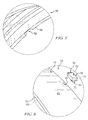
Fig. 6 is a detail perspective view of the blade track included in the turbine shroud ofFigs. 3 and4 showing that the blade track includes an annular runner and an insert; -
Fig. 7 is a detail perspective view of the blade track shown inFig. 6 with the insert coupled to the annular runner to provide a radially extending key; -
Fig. 8 is a cross-sectional view of the blade track ofFig. 7 showing that the insert extends partway through the annular runner and is coupled to the annular runner by a braze layer; -
Fig. 9 is a detail perspective view of the blade track shown inFigs. 2-8 showing that the insert includes a stem that extends into the annular runner and a cap that extends from the stem in both directions circumferentially around the annular runner and that extends axially forward along the annular runner; -
Fig. 10 is a detail perspective view of the insert shown inFigs. 2-9 ; -
Fig. 11 is an exploded detail perspective view of another blade track adapted for use in the gas turbine engine ofFig. 1 showing that the blade track includes an annular runner and an insert; -
Fig. 12 is a detail perspective view of the blade track shown inFig. 11 with the insert coupled to the annular runner to provide a radially extending key; -
Fig. 13 is a partial cross-sectional view of the blade track ofFig. 12 ; -
Fig. 14 is a perspective view of the insert ofFigs. 11-13 showing that the insert includes a stem that extends into the annular runner and a cap that extends from the stem in both directions circumferentially around the annular runner and that extends in both directions axially along the annular runner; -
Fig. 15 is a bottom view of the insert ofFigs. 11-14 showing that the cap extends about the same amount in each circumferential direction and in each axial direction from the stem; -
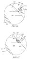
Fig. 16 is an exploded detail perspective view of another blade track adapted for use in the gas turbine engine ofFig. 1 showing that the blade track includes an annular runner and an insert; -
Fig. 17 is a detail perspective view of the blade track shown inFig. 16 looking aft with the insert coupled to the annular runner to provide a radially extending key; and -
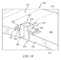
Fig. 18 is a detail perspective view of the blade track shown inFig. 16 looking forward showing that the insert includes a stem that extends through the annular runner and a cap that cooperates with the stem to form a lower-case t shape. - For the purposes of promoting an understanding of the principles of the disclosure, reference will now be made to a number of illustrative embodiments illustrated in the drawings and specific language will be used to describe the same.
-
Fig. 1 is an illustrative aerospacegas turbine engine 10 cut-away to show that theengine 10 includes anoutput shaft 12, acompressor 14, acombustor 16, and aturbine 18 all mounted to acase 20. Theoutput shaft 12 is configured to be coupled to a propeller and is driven by theturbine 18. Thecompressor 14 compresses and delivers air to thecombustor 16. Thecombustor 16 mixes fuel with the compressed air received from thecompressor 14 and ignites the fuel. The hot high pressure products of the combustion reaction in thecombustor 16 are directed into theturbine 18 and theturbine 18 extracts work to drive thecompressor 14 and theoutput shaft 12. - The
turbine 18 illustratively includes staticturbine vane assemblies turbine wheel assembly 26 as shown inFigs. 1 and 2 . Eachvane assembly vanes turbine wheel assembly 26 includes a plurality ofcorresponding blades 36. Thevanes vane assembly 21 direct the combustion products from thecombustor 16 toward theblades 36 of theturbine wheel assemblies 26. Theblades 36 are in turn pushed by the combustion products to cause theturbine wheel assembly 26 to rotate; thereby, driving the rotating components of thecompressor 14 and/or theoutput shaft 12. - The
turbine 18 also includes aturbine shroud 46 that extends around theturbine wheel assembly 26 to block combustion products from passing over theblades 36 without pushing theblades 36 to rotate. The exemplary firststage turbine shroud 46, shown inFig. 2 , extends around the first stageturbine wheel assembly 26 and is sized to block most combustion products from passing over theblades 36 without pushing theblades 36 to rotate. Combustion products that are allowed to pass over theblades 36 do not push theblades 36 and such passed-over products contribute to lost performance within theengine 10. - The
turbine shroud 46 illustratively includes acarrier 48, a blade track (sometimes called seal ring) 50, and aretainer 52 as shown inFigs. 2 and3 . Thecarrier 48 is an annular, round metallic component and is configured to support theblade track 50 in position adjacent to theblades 36 of theturbine wheel assembly 26. Theillustrative blade track 50 is concentric with and nested into thecarrier 48 along a rotational axis 11 of theengine 10. Theretainer 52 engages both thecarrier 48 and theblade track 50 to position thecarrier 48 and the blade track relative to other static turbine components. In some embodiments, thecarrier 48 may be made up of a number of segments that extend only part-way around the axis 11. - In the illustrative embodiment, the
blade track 50 includes anannular runner 51 and a plurality ofinserts 53 as shown inFig. 4 . Theannular runner 51 is illustratively formed to include a plurality ofcutouts 55 spaced circumferentially apart and sized to receive the plurality ofinserts 53 as suggested inFigs. 4 and6-8 . The plurality ofinserts 53 are coupled to theannular runner 51 by arranging eachinsert 53 in a correspondingcutout 55 and bonding theinserts 53 to theannular runner 51 via brazing which adds abraze layer 57 between theannular runner 51 and each insert 53 as shown inFigs. 7 and 8 . - In some embodiments, instead of bonding the
inserts 53 to theannular runner 51 using abraze layer 57, theinserts 53 may be integrally woven into a preform that is later hardened to create theannular runner 51 so that the inserts are bonded to theannular runner 51. In some such embodiments, theinserts 53 are machined after hardening of theannular runner 51 so that theinserts 53 have a predetermined shape/orientation relative to the geometry of theannular runner 51. - In some embodiments, instead of bonding the
inserts 53 to theannular runner 51 using abraze layer 57, theinserts 53 may be welded to theannular runner 51 creating a weld between theinserts 53 and the annular runner 51 (similar to the braze layer 57). Filler materials would be used to form the welds and such filler materials may include silicon, a transition metal silicide, and/or a MAX phase material. - In some embodiments, instead of bonding the
inserts 53 to theannular runner 51 using abraze layer 57, theinserts 53 may be co-processed with theannular runner 51 creating an integrated or monolithic component made up of theinserts 53 and theannular runner 51. Co-processing may include partially densifying each of theinserts 53 and theannular runner 51 into preforms, assembling the preforms, and further densifying the assembly to produce an integrated or monolithic component in which matrix material bonds theinserts 53 to theannular runner 51. - The
annular runner 51 is illustratively made from a ceramic material; and, more particularly, a ceramic matrix composite (CMC) including silicon carbide fibers and silicon carbide matrix. For purposes of this application, a ceramic material is any monolithic ceramic or composite in which at least one constituent is a ceramic. In other embodiments, theannular runner 51 may be made of other metallic, non-metallic, or composite materials with low coefficients of thermal expansion. - Similarly, in the illustrative embodiment, each
insert 53 is made from a ceramic material; and, more particularly, a ceramic matrix composite (CMC) including silicon carbide fibers and silicon carbide matrix. In other embodiments, eachinsert 53 may be made from monolithic silicon carbide, dense chopped fiber reinforced silicon carbide, monolithic silicon nitride based materials, monolitihic aluminum oxide, whisker reinforced aluminum oxide, and/or MAX phase materials (e.g. Ti3SIC2, Ti2AIC, etc.). In still other embodiments, eachinsert 53 may be made of other metallic, non-metallic, or composite materials with low coefficients of thermal expansion that are compatible with both thecarrier 48 and theannular runner 51. - The
braze layer 57 is illustratively made from a transition metal and silicon. More particularly, some embodiments of theillustrative braze layer 57 include a combination of molybdenum (Mo) and silicon (Si), a combination of Niobium (Nb) and silicon (Si), or a combination of titanium (Ti) and silicon (Si). In some embodiments, thebraze layer 57 may also include fluxing agents such as boron (B) and/or carbon (C). In some embodiments, the braze layer may include filler materials such as silicon carbide, polycarbosilanes, carbon, MAX phase materials, aluminum oxide, or other types of filler. - The illustrative inserts 53 have an
aft side 71 that is coplanar with the aft side of theannular runner 51 as shown inFig. 9 . Eachinsert 53 is formed to include astem 91 and acap 92 as shown inFig. 6 . The stems 91 are arranged in correspondingcutouts 55 formed in theannular runner 51. Thecaps 92 are arranged outside thecutouts 55. Thecaps 92 extend from the stems 91 in both radial directions around the outer radial surface of therunner 51 and extend in the axial direction forward from thestem 91 along the outer radial surface of the annularceramic runner 51. The braze layers 57 bonding the inserts to therunner 51 are illustratively arranged in the cutout and between the radiallyouter surface 61 of the annular ceramic runner and thecaps 92 of theinserts 53. - The
cutouts 55 are illustratively sized to receive a portion of theinsert 53 as shown inFigs. 6-8 . In other embodiments, the cutouts may be other shapes corresponding to theinserts 53. Additionally, theillustrative cutouts 55 extend inward in a radial direction all the way through theannular runner 51 from an outerradial surface 61 to an innerradial surface 63 of theannular runner 51 as shown inFig. 6 . In other embodiments, thecutouts 55 may extend part way through theannular runner 51 in the radial direction. - The
annular runner 51 has a relatively low coefficient of thermal expansion because of its composition. Considering the relatively small coefficient of thermal expansion, theannular runner 51 can be designed to maintain a small gap between theblade track 50 and theblades 36 thereby improving performance of theengine 10. - Additionally, the
annular runner 51 is a unitary component forming a full hoop as shown inFig. 4 . Theannular runner 51 is a component of one-piece, continuous construction, rather than as a series of joined segments. This construction eliminates gaps that may be formed between parts of a multi-piece (or segmented) runner. The one-piece full hoop of theannular runner 51 encourages uniform radial expansion of theblade track 50 at high temperatures. Uniform radial expansion of theblade track 50 allows theblade track 50 to remain round at high temperatures which results in the ability to further maintain a small gap between theblades 36 and theblade track 50 while hot combustion products are being directed over theblades 36 and theblade track 50. - To accommodate the connection of the
CMC blade track 50 to the metallic carrier 48 (which has a relatively high coefficient of thermal expansion), theturbine shroud 46 includes a cross-key connection 54 that is formed between thecarrier 48 and theblade track 50 as shown, for example, inFigs. 2 and4 . The cross-key connection 54 locates theblade track 50 relative to thecarrier 48 while allowing radial translation of theblade track 50 relative to thecarrier 48. The cross-key connection 54 illustratively includes a plurality ofkeys 56 and a plurality of correspondingkeyways 58 sized and arranged to receive the plurality ofkeys 56. - In the illustrative embodiment, the
keys 56 are provided by thecaps 92 of theinserts 53 that extend outward in the radial direction from theannular runner 51. Thekeyways 58 are formed in thecarrier 48 and extend outward in the radial direction into thecarrier 48 as shown inFig. 5 . - Referring now to
Fig. 4 , thecarrier 48 is illustratively formed to include aconnection flange 62, aconnector 64, and asupport band 68. Theconnection flange 62 is formed to include a bolt-hole pattern 66 adapted to be bolted between a combustor-case section 76 and a turbine-case section 78 included in thecase 20. In another embodiment, theconnection flange 62 could be hung from the case rather than bolted. Theconnector 64 extends inwardly in the radial direction and rearwardly in an axial direction from theconnection flange 62 to form a frustoconical shape. Thesupport band 68 extends inwardly in the radial direction from theconnector 64 and theconnection flange 62. - The
support band 68 forms a downwardly-openingchannel 80 that faces theblade track 50 as shown inFig. 4 . The downwardly-openingchannel 80 is exposed to fluid communication with air radially outwardly of theblade track 50 via avent hole pattern 69 formed in thesupport band 68 and avent hole pattern 65 formed in theconnector 64. In the illustrative embodiment, the plurality ofkeyways 58 extend outward in the radial direction into thesupport band 68 as shown inFig. 5 . - The
retainer 52 is an annular metallic ring with a linear cross section as shown inFigs. 3 and4 . Theretainer 52 engages the aft side 82 of thesupport band 68 and theaft side 71 of theblade track 50 to locate thecarrier 48 and theblade track 50 relative to the secondstage vane assembly 22 as shown inFig. 3 . - According to at least one method of assembling the
turbine shroud 46, a user first places each of theinserts 53 into a correspondingcutout 55 formed in theannular runner 51. Then the user brazes theinserts 53 in place forming thebraze layer 57 between eachinsert 53 and theannular runner 51 to form theblade track 50. - When the
blade track 50 is completed, the user rotates theblade track 50 to a predetermined orientation relative to theretainer 48 so that thekeys 56 are aligned correspondingkeyways 58. Then the user nests theblade track 50 into theretainer 48 so that theblade track 50 is concentric with the retainer. Next, the user inserts thekeys 56 of theblade track 50 into the correspondingkeyways 58 formed in thecarrier 48 to thereby establish the cross-key connection 54 between theblade track 50 and thecarrier 48. - Another
illustrative blade track 250 is shown inFigs. 11-15 . Theblade track 250 is configured for use inengine 10 and is substantially similar to theblade track 50 shown inFigs. 1-10 and described herein. Accordingly, similar reference numbers in the 200 series indicate features that are common between theblade track 50 and theblade track 250. The description of theengine 10 and theblade track 50 is hereby incorporated by reference to apply to theblade track 250, except in instances when it conflicts with the specific description and drawings of theblade track 250. - Unlike
blade track 50, thecutout 255 formed in theannular runner 251 is spaced apart from theforward side 273 and theaft side 271 of the annularceramic runner 251 as shown inFig. 11 . Thecutout 255 is illustratively a blind hole that only extends part way through theannular runner 251. In other embodiments, the cutout may extend all the way through therunner 251. - Additionally, the
cap 292 of theinserts 253 extends along the outerradial surface 261 of the annularceramic runner 251 in both axial directions. To accommodate the additional area of thecap 292, thebraze layer 257 is arranged between thecap 292 and the outerradial surface 261 all the way around thestem 291. Finally, in this embodiment, an aft side of thecap 292 is arranged to be coplanar with theaft side 271 of therunner 251 as shown inFig. 13 . - Another
illustrative blade track 350 is shown inFigs. 16-18 . Theblade track 350 is configured for use inengine 10 and is substantially similar to theblade track 50 shown inFigs. 1-10 and described herein. Accordingly, similar reference numbers in the 300 series indicate features that are common between theblade track 50 and theblade track 350. The description of theengine 10 and theblade track 50 is hereby incorporated by reference to apply to theblade track 350, except in instances when it conflicts with the specific description and drawings of theblade track 350. - Unlike
blade track 50, thecap 392 of eachinsert 353 includes a radially-inner portion 393 and a radiallyouter portion 394 as shown inFig. 18 . The radially-inner portion 393 extends circumferentially along the outerradial surface 361 of the annularceramic runner 351 in both circumferential directions. The radially-outer portion 394 extends radially outward from thestem 391 without extending circumferentially along the outerradial surface 361 of the annularceramic runner 351. Thecap 392 also includesfillets 395 that form a radius between the radially-outer portion 394 of thecap 392 and the radially-inner portion 393 of the cap on both circumferential sides of the radially-outer portion 394 of thecap 392. Accordingly, thestem 391 and thecap 392 cooperate to form a lower case t shape. - While the disclosure has been illustrated and described in detail in the foregoing drawings and description, the same is to be considered as exemplary and not restrictive in character, it being understood that only illustrative embodiments thereof have been shown and described and that all changes and modifications that come within the spirit of the disclosure are desired to be protected.
Claims (15)
- A turbine blade track comprising
an annular ceramic runner formed to include a plurality of cutouts extending inward in a radial direction from an outer radial surface of the annular ceramic runner toward an inner radial surface of the annular ceramic runner, and
a plurality of inserts coupled to the annular ceramic runner, each insert including a stem arranged in the cutout and a cap arranged outside the cutout that extends from the stem in a circumferential direction and in an axial direction along the outer radial surface of the annular ceramic runner. - The turbine blade track of claim 1, further comprising a plurality of braze layers arranged between the annular ceramic runner and each of the plurality of inserts.
- The turbine blade track of claim 2, wherein the braze layers arranged in the cutout and the braze layers are arranged between the radially outer surface of the annular ceramic runner and the caps of the inserts.
- The turbine blade track of claim 3, wherein an aft side of each of the plurality of inserts is coplanar with an aft side of the annular ceramic runner.
- The turbine blade track of claim 3, wherein the cutout is spaced apart from a forward side of the annular ceramic runner and from an aft side of the annular ceramic runner, optionally wherein the cap extends along the outer radial surface of the annular ceramic runner in both axial directions.
- The turbine blade track of claim 2, wherein the braze layers comprise silicon and a transition metal.
- The turbine blade track of claim 6, wherein the braze layers include a fluxing agent including at least one of boron and carbon, optionally wherein the braze layers comprise a filler material including at least one of silicon carbide, polycarbosilanes, carbon, aluminum oxide, and MAX phase material.
- The turbine blade track of claim 1, wherein the annular ceramic runner and the inserts both consist essentially of ceramic matrix composite.
- A turbine blade track comprising
an annular ceramic runner arranged around a central axis and formed to include a plurality of cutouts extending inward in a radial direction from an outer radial surface of the annular ceramic runner toward an inner radial surface of the annular ceramic runner,
a plurality of inserts coupled to the annular ceramic runner, each insert including a stem arranged in the cutout and a cap arranged outside the cutout,
and a plurality of braze layers arranged between the annular ceramic runner and each of the plurality of inserts,
wherein the cap of each insert includes a radially-inner portion that extends circumferentially along the outer radial surface of the annular ceramic runner in both circumferential directions and a radially-outer portion that extends radially outward from the stem without extending circumferentially along the outer radial surface of the annular ceramic runner. - The turbine blade track of claim 9, wherein the cap includes fillets that form a radius between the radially outer portion of the cap and the radially inner portion of the cap on at least two sides of the radially outer portion of the cap.
- The turbine blade track of claim 9, wherein:(i) the stem and the cap cooperate to form a lower case t shape; or(ii) the cutout extends all the way through the annular ceramic runner from the outer radial surface to inner radial surface; or(iii) an inner radial surface of the stem is flush with the inner radial surface of the annular ceramic runner.
- A turbine shroud comprising
a metallic carrier that extends around an engine axis and is formed to include a plurality of circumferentially spaced apart keyways that extend axially into the carrier,
a blade track including a ceramic annular runner formed to include a cutout, an insert arranged to extend into the cutout, and a braze layer bonded to the ceramic annular runner and the cutout,
wherein the insert includes a stem arranged in the cutout and a cap that extends outwardly in the radial direction from the stem to provide a key that extends into a corresponding keyway formed in the metallic carrier to establish a cross-key connection between the blade track and the metallic carrier and the cap extends along the outer radial surface of the annular ceramic runner in an axial direction. - The turbine blade track of claim 12, wherein an aft side of the insert is coplanar with an aft side of the annular ceramic runner.
- The turbine blade track of claim 12, wherein the cap extends in both directions axially from the stem.
- The turbine blade track of claim 14, wherein the cutout is spaced apart from a forward side of the annular ceramic runner and from an aft side of the annular ceramic runner, optionally wherein an aft side of the cap is coplanar with an aft side of the annular ceramic runner.
Applications Claiming Priority (1)
| Application Number | Priority Date | Filing Date | Title |
|---|---|---|---|
| US201462072111P | 2014-10-29 | 2014-10-29 |
Publications (1)
| Publication Number | Publication Date |
|---|---|
| EP3018294A1 true EP3018294A1 (en) | 2016-05-11 |
Family
ID=54266494
Family Applications (1)
| Application Number | Title | Priority Date | Filing Date |
|---|---|---|---|
| EP15188791.6A Withdrawn EP3018294A1 (en) | 2014-10-29 | 2015-10-07 | Turbine shroud with locating inserts |
Country Status (2)
| Country | Link |
|---|---|
| US (1) | US10190434B2 (en) |
| EP (1) | EP3018294A1 (en) |
Families Citing this family (20)
| Publication number | Priority date | Publication date | Assignee | Title |
|---|---|---|---|---|
| EP2735796B1 (en) * | 2012-11-23 | 2020-01-01 | Ansaldo Energia IP UK Limited | Wall of a hot gas path component of a gas turbine and method for enhancing operational behaviour of a gas turbine |
| CA2896500A1 (en) * | 2013-01-29 | 2014-08-07 | Rolls-Royce Corporation | Turbine shroud |
| EP2971577B1 (en) | 2013-03-13 | 2018-08-29 | Rolls-Royce Corporation | Turbine shroud |
| US10190434B2 (en) | 2014-10-29 | 2019-01-29 | Rolls-Royce North American Technologies Inc. | Turbine shroud with locating inserts |
| CA2915370A1 (en) | 2014-12-23 | 2016-06-23 | Rolls-Royce Corporation | Full hoop blade track with axially keyed features |
| CA2915246A1 (en) | 2014-12-23 | 2016-06-23 | Rolls-Royce Corporation | Turbine shroud |
| EP3045674B1 (en) | 2015-01-15 | 2018-11-21 | Rolls-Royce Corporation | Turbine shroud with tubular runner-locating inserts |
| CA2924855A1 (en) | 2015-04-29 | 2016-10-29 | Rolls-Royce Corporation | Keystoned blade track |
| US20170122109A1 (en) * | 2015-10-29 | 2017-05-04 | General Electric Company | Component for a gas turbine engine |
| US10240476B2 (en) | 2016-01-19 | 2019-03-26 | Rolls-Royce North American Technologies Inc. | Full hoop blade track with interstage cooling air |
| US10287906B2 (en) | 2016-05-24 | 2019-05-14 | Rolls-Royce North American Technologies Inc. | Turbine shroud with full hoop ceramic matrix composite blade track and seal system |
| US10415415B2 (en) | 2016-07-22 | 2019-09-17 | Rolls-Royce North American Technologies Inc. | Turbine shroud with forward case and full hoop blade track |
| CA2976586A1 (en) * | 2016-08-15 | 2018-02-15 | Summit Esp, Llc | Torque transmitting key for electric submersible pumps |
| CN110192037B (en) | 2016-11-28 | 2021-04-27 | 哈里伯顿能源服务公司 | Torque Transfer Systems for Centrifugal Pumps |
| US11149590B2 (en) | 2017-06-21 | 2021-10-19 | Rolls-Royce Corporation | Ceramic matrix composite joints |
| US10954809B2 (en) | 2017-06-26 | 2021-03-23 | Rolls-Royce High Temperature Composites Inc. | Ceramic matrix full hoop blade track |
| US11078802B2 (en) * | 2019-05-10 | 2021-08-03 | Rolls-Royce Plc | Turbine engine assembly with ceramic matrix composite components and end face seals |
| US11162425B2 (en) * | 2019-06-11 | 2021-11-02 | Rolls-Royce Corporation | Assembly fixture |
| US11255210B1 (en) * | 2020-10-28 | 2022-02-22 | Rolls-Royce Corporation | Ceramic matrix composite turbine shroud assembly with joined cover plate |
| US11939888B2 (en) * | 2022-06-17 | 2024-03-26 | Rtx Corporation | Airfoil anti-rotation ring and assembly |
Citations (2)
| Publication number | Priority date | Publication date | Assignee | Title |
|---|---|---|---|---|
| WO2014120334A1 (en) * | 2013-01-29 | 2014-08-07 | Sippel Aaron D | Turbine shroud |
| US20140271144A1 (en) * | 2013-03-13 | 2014-09-18 | Rolls-Royce North American Technologies, Inc. | Turbine shroud |
Family Cites Families (82)
| Publication number | Priority date | Publication date | Assignee | Title |
|---|---|---|---|---|
| US3601414A (en) | 1969-10-29 | 1971-08-24 | Ford Motor Co | Ceramic crossarm seal for gas turbine regenerators |
| US4087199A (en) | 1976-11-22 | 1978-05-02 | General Electric Company | Ceramic turbine shroud assembly |
| US4477086A (en) | 1982-11-01 | 1984-10-16 | United Technologies Corporation | Seal ring with slidable inner element bridging circumferential gap |
| FR2572394B1 (en) | 1984-10-30 | 1986-12-19 | Snecma | METHOD FOR MANUFACTURING A CERAMIC TURBINE RING INTEGRATED WITH AN ANNULAR METAL SUPPORT |
| FR2574473B1 (en) | 1984-11-22 | 1987-03-20 | Snecma | TURBINE RING FOR A GAS TURBOMACHINE |
| FR2580033A1 (en) | 1985-04-03 | 1986-10-10 | Snecma | Elastically suspended turbine ring for a turbine machine |
| GB2206651B (en) | 1987-07-01 | 1991-05-08 | Rolls Royce Plc | Turbine blade shroud structure |
| US4986737A (en) * | 1988-12-29 | 1991-01-22 | General Electric Company | Damped gas turbine engine airfoil row |
| US5104287A (en) | 1989-09-08 | 1992-04-14 | General Electric Company | Blade tip clearance control apparatus for a gas turbine engine |
| US5163809A (en) | 1991-04-29 | 1992-11-17 | Pratt & Whitney Canada, Inc. | Spiral wound containment ring |
| JPH09250304A (en) | 1996-03-18 | 1997-09-22 | Ishikawajima Harima Heavy Ind Co Ltd | Ceramic shroud ring support structure |
| JPH09264104A (en) | 1996-03-27 | 1997-10-07 | Ishikawajima Harima Heavy Ind Co Ltd | Ceramic shroud ring |
| US5738490A (en) | 1996-05-20 | 1998-04-14 | Pratt & Whitney Canada, Inc. | Gas turbine engine shroud seals |
| US6142731A (en) | 1997-07-21 | 2000-11-07 | Caterpillar Inc. | Low thermal expansion seal ring support |
| US6315519B1 (en) | 1998-09-28 | 2001-11-13 | General Electric Company | Turbine inner shroud and turbine assembly containing such inner shroud |
| US6517313B2 (en) * | 2001-06-25 | 2003-02-11 | Pratt & Whitney Canada Corp. | Segmented turbine vane support structure |
| US6896483B2 (en) | 2001-07-02 | 2005-05-24 | Allison Advanced Development Company | Blade track assembly |
| US6758386B2 (en) | 2001-09-18 | 2004-07-06 | The Boeing Company | Method of joining ceramic matrix composites and metals |
| FR2831615B1 (en) * | 2001-10-31 | 2004-01-02 | Snecma Moteurs | SECTORIZED FIXED RECTIFIER FOR A TURBOMACHINE COMPRESSOR |
| US6733233B2 (en) | 2002-04-26 | 2004-05-11 | Pratt & Whitney Canada Corp. | Attachment of a ceramic shroud in a metal housing |
| US6726448B2 (en) | 2002-05-15 | 2004-04-27 | General Electric Company | Ceramic turbine shroud |
| US6758653B2 (en) | 2002-09-09 | 2004-07-06 | Siemens Westinghouse Power Corporation | Ceramic matrix composite component for a gas turbine engine |
| US6910853B2 (en) | 2002-11-27 | 2005-06-28 | General Electric Company | Structures for attaching or sealing a space between components having different coefficients or rates of thermal expansion |
| US7435049B2 (en) | 2004-03-30 | 2008-10-14 | General Electric Company | Sealing device and method for turbomachinery |
| US7090459B2 (en) | 2004-03-31 | 2006-08-15 | General Electric Company | Hybrid seal and system and method incorporating the same |
| FR2871846B1 (en) | 2004-06-17 | 2006-09-29 | Snecma Moteurs Sa | GAS TURBINE COMBUSTION CHAMBER SUPPORTED IN A METALLIC CASING BY CMC BONDING FEATURES |
| US7195452B2 (en) | 2004-09-27 | 2007-03-27 | Honeywell International, Inc. | Compliant mounting system for turbine shrouds |
| US7217089B2 (en) | 2005-01-14 | 2007-05-15 | Pratt & Whitney Canada Corp. | Gas turbine engine shroud sealing arrangement |
| US7374396B2 (en) | 2005-02-28 | 2008-05-20 | General Electric Company | Bolt-on radial bleed manifold |
| FR2891300A1 (en) | 2005-09-23 | 2007-03-30 | Snecma Sa | DEVICE FOR CONTROLLING PLAY IN A GAS TURBINE |
| US7810816B1 (en) | 2005-12-13 | 2010-10-12 | Horace P. Halling | Seal |
| JP4918263B2 (en) * | 2006-01-27 | 2012-04-18 | 三菱重工業株式会社 | Stator blade ring of axial compressor |
| US7665960B2 (en) | 2006-08-10 | 2010-02-23 | United Technologies Corporation | Turbine shroud thermal distortion control |
| US7771160B2 (en) | 2006-08-10 | 2010-08-10 | United Technologies Corporation | Ceramic shroud assembly |
| US7686575B2 (en) * | 2006-08-17 | 2010-03-30 | Siemens Energy, Inc. | Inner ring with independent thermal expansion for mounting gas turbine flow path components |
| US7753643B2 (en) | 2006-09-22 | 2010-07-13 | Siemens Energy, Inc. | Stacked laminate bolted ring segment |
| GB0703827D0 (en) | 2007-02-28 | 2007-04-11 | Rolls Royce Plc | Rotor seal segment |
| FR2913718B1 (en) | 2007-03-15 | 2009-06-05 | Snecma Propulsion Solide Sa | TURBINE RING ASSEMBLY FOR GAS TURBINE |
| FR2913717A1 (en) | 2007-03-15 | 2008-09-19 | Snecma Propulsion Solide Sa | Ring assembly for e.g. aircraft engine gas turbine, has centering unit constituted of metallic ring gear and bracket, and centering complete ring, where elastically deformable tab blocks rotation of ring around axis of ring |
| US7914256B2 (en) | 2007-04-17 | 2011-03-29 | General Electric Company | Articles made from composite materials having toughened and untoughened regions |
| US8061977B2 (en) | 2007-07-03 | 2011-11-22 | Siemens Energy, Inc. | Ceramic matrix composite attachment apparatus and method |
| US8047773B2 (en) | 2007-08-23 | 2011-11-01 | General Electric Company | Gas turbine shroud support apparatus |
| US8568091B2 (en) | 2008-02-18 | 2013-10-29 | United Technologies Corporation | Gas turbine engine systems and methods involving blade outer air seals |
| CH699066A1 (en) | 2008-07-01 | 2010-01-15 | Alstom Technology Ltd | Seal and seal assembly for containing leakage flows between adjacent components of turbomachines, particularly gas turbines. |
| US8322983B2 (en) | 2008-09-11 | 2012-12-04 | Siemens Energy, Inc. | Ceramic matrix composite structure |
| FR2938873B1 (en) | 2008-11-21 | 2014-06-27 | Turbomeca | POSITIONING DEVICE FOR RING SEGMENT |
| US7988395B2 (en) | 2009-01-23 | 2011-08-02 | Steffier Wayne S | Mechanical fastener system for high-temperature structural assemblies |
| US8555647B2 (en) | 2009-03-11 | 2013-10-15 | General Electric Company | Methods and apparatus for providing a sacrificial shield for a fuel injector |
| US8393858B2 (en) | 2009-03-13 | 2013-03-12 | Honeywell International Inc. | Turbine shroud support coupling assembly |
| US8113771B2 (en) | 2009-03-20 | 2012-02-14 | General Electric Company | Spring system designs for active and passive retractable seals |
| US20120177488A1 (en) | 2009-03-27 | 2012-07-12 | General Electric Company | Process for joining silicon-containing ceramic articles and components produced thereby |
| US8235670B2 (en) | 2009-06-17 | 2012-08-07 | Siemens Energy, Inc. | Interlocked CMC airfoil |
| US8167546B2 (en) | 2009-09-01 | 2012-05-01 | United Technologies Corporation | Ceramic turbine shroud support |
| US8079807B2 (en) | 2010-01-29 | 2011-12-20 | General Electric Company | Mounting apparatus for low-ductility turbine shroud |
| US8784052B2 (en) | 2010-05-10 | 2014-07-22 | Hamilton Sundstrand Corporation | Ceramic gas turbine shroud |
| US8740552B2 (en) | 2010-05-28 | 2014-06-03 | General Electric Company | Low-ductility turbine shroud and mounting apparatus |
| FR2961553B1 (en) | 2010-06-18 | 2012-08-31 | Snecma | ANGULAR RECTIFIER SECTOR FOR TURBOMACHINE COMPRESSOR, TURBOMACHINE RECTIFIER AND TURBOMACHINE COMPRISING SUCH A SECTOR |
| JP5569194B2 (en) | 2010-07-02 | 2014-08-13 | 株式会社Ihi | Method for manufacturing shroud segment |
| US8684674B2 (en) * | 2010-10-29 | 2014-04-01 | General Electric Company | Anti-rotation shroud for turbine engines |
| US8926270B2 (en) | 2010-12-17 | 2015-01-06 | General Electric Company | Low-ductility turbine shroud flowpath and mounting arrangement therefor |
| US8684689B2 (en) | 2011-01-14 | 2014-04-01 | Hamilton Sundstrand Corporation | Turbomachine shroud |
| US8985944B2 (en) * | 2011-03-30 | 2015-03-24 | General Electric Company | Continuous ring composite turbine shroud |
| US8647055B2 (en) | 2011-04-18 | 2014-02-11 | General Electric Company | Ceramic matrix composite shroud attachment system |
| US8790067B2 (en) | 2011-04-27 | 2014-07-29 | United Technologies Corporation | Blade clearance control using high-CTE and low-CTE ring members |
| US20120301269A1 (en) | 2011-05-26 | 2012-11-29 | Ioannis Alvanos | Clearance control with ceramic matrix composite rotor assembly for a gas turbine engine |
| US9915154B2 (en) | 2011-05-26 | 2018-03-13 | United Technologies Corporation | Ceramic matrix composite airfoil structures for a gas turbine engine |
| US8770931B2 (en) | 2011-05-26 | 2014-07-08 | United Technologies Corporation | Hybrid Ceramic Matrix Composite vane structures for a gas turbine engine |
| US8834106B2 (en) | 2011-06-01 | 2014-09-16 | United Technologies Corporation | Seal assembly for gas turbine engine |
| US8651497B2 (en) | 2011-06-17 | 2014-02-18 | United Technologies Corporation | Winged W-seal |
| US8739547B2 (en) | 2011-06-23 | 2014-06-03 | United Technologies Corporation | Gas turbine engine joint having a metallic member, a CMC member, and a ceramic key |
| US8511975B2 (en) | 2011-07-05 | 2013-08-20 | United Technologies Corporation | Gas turbine shroud arrangement |
| US20130011248A1 (en) | 2011-07-05 | 2013-01-10 | United Technologies Corporation | Reduction in thermal stresses in monolithic ceramic or ceramic matrix composite shroud |
| US9726043B2 (en) | 2011-12-15 | 2017-08-08 | General Electric Company | Mounting apparatus for low-ductility turbine shroud |
| US20130177411A1 (en) | 2012-01-05 | 2013-07-11 | General Electric Company | System and method for sealing a gas path in a turbine |
| US9011079B2 (en) | 2012-01-09 | 2015-04-21 | General Electric Company | Turbine nozzle compartmentalized cooling system |
| US9458726B2 (en) | 2013-03-13 | 2016-10-04 | Rolls-Royce Corporation | Dovetail retention system for blade tracks |
| US9422865B2 (en) | 2013-03-14 | 2016-08-23 | Rolls-Royce Corporation | Bi-metal fastener for thermal growth compensation |
| WO2014143225A1 (en) | 2013-03-15 | 2014-09-18 | Peter Loftus | Composite retention feature |
| US10190434B2 (en) | 2014-10-29 | 2019-01-29 | Rolls-Royce North American Technologies Inc. | Turbine shroud with locating inserts |
| CA2915246A1 (en) | 2014-12-23 | 2016-06-23 | Rolls-Royce Corporation | Turbine shroud |
| EP3045674B1 (en) | 2015-01-15 | 2018-11-21 | Rolls-Royce Corporation | Turbine shroud with tubular runner-locating inserts |
| CA2916710A1 (en) | 2015-01-29 | 2016-07-29 | Rolls-Royce Corporation | Seals for gas turbine engines |
-
2015
- 2015-09-29 US US14/869,532 patent/US10190434B2/en active Active
- 2015-10-07 EP EP15188791.6A patent/EP3018294A1/en not_active Withdrawn
Patent Citations (2)
| Publication number | Priority date | Publication date | Assignee | Title |
|---|---|---|---|---|
| WO2014120334A1 (en) * | 2013-01-29 | 2014-08-07 | Sippel Aaron D | Turbine shroud |
| US20140271144A1 (en) * | 2013-03-13 | 2014-09-18 | Rolls-Royce North American Technologies, Inc. | Turbine shroud |
Also Published As
| Publication number | Publication date |
|---|---|
| US20160123171A1 (en) | 2016-05-05 |
| US10190434B2 (en) | 2019-01-29 |
Similar Documents
| Publication | Publication Date | Title |
|---|---|---|
| US10190434B2 (en) | Turbine shroud with locating inserts | |
| US10094233B2 (en) | Turbine shroud | |
| US10738642B2 (en) | Turbine engine assembly with tubular locating inserts | |
| US10371008B2 (en) | Turbine shroud | |
| US11725535B2 (en) | Vane assembly for a gas turbine engine | |
| US9752592B2 (en) | Turbine shroud | |
| US11053806B2 (en) | Brazed blade track for a gas turbine engine | |
| EP3088664B1 (en) | Composite keystoned blade track | |
| EP3023581A1 (en) | Turbine disk assembly including ceramic matrix composite blades and method of manufacture | |
| US10577951B2 (en) | Gas turbine engine with dovetail connection having contoured root | |
| US10954809B2 (en) | Ceramic matrix full hoop blade track | |
| US10934862B2 (en) | Turbine wheel assembly | |
| EP3450699B1 (en) | Ceramic matrix composite blade track for a gas turbine engine and method of making the same | |
| US10370985B2 (en) | Full hoop blade track with axially keyed features |
Legal Events
| Date | Code | Title | Description |
|---|---|---|---|
| PUAI | Public reference made under article 153(3) epc to a published international application that has entered the european phase |
Free format text: ORIGINAL CODE: 0009012 |
|
| AK | Designated contracting states |
Kind code of ref document: A1 Designated state(s): AL AT BE BG CH CY CZ DE DK EE ES FI FR GB GR HR HU IE IS IT LI LT LU LV MC MK MT NL NO PL PT RO RS SE SI SK SM TR |
|
| AX | Request for extension of the european patent |
Extension state: BA ME |
|
| STAA | Information on the status of an ep patent application or granted ep patent |
Free format text: STATUS: REQUEST FOR EXAMINATION WAS MADE |
|
| 17P | Request for examination filed |
Effective date: 20161103 |
|
| RBV | Designated contracting states (corrected) |
Designated state(s): AL AT BE BG CH CY CZ DE DK EE ES FI FR GB GR HR HU IE IS IT LI LT LU LV MC MK MT NL NO PL PT RO RS SE SI SK SM TR |
|
| STAA | Information on the status of an ep patent application or granted ep patent |
Free format text: STATUS: EXAMINATION IS IN PROGRESS |
|
| 17Q | First examination report despatched |
Effective date: 20181106 |
|
| GRAP | Despatch of communication of intention to grant a patent |
Free format text: ORIGINAL CODE: EPIDOSNIGR1 |
|
| STAA | Information on the status of an ep patent application or granted ep patent |
Free format text: STATUS: GRANT OF PATENT IS INTENDED |
|
| INTG | Intention to grant announced |
Effective date: 20201125 |
|
| STAA | Information on the status of an ep patent application or granted ep patent |
Free format text: STATUS: THE APPLICATION IS DEEMED TO BE WITHDRAWN |
|
| 18D | Application deemed to be withdrawn |
Effective date: 20210407 |