EP3018240A1 - Spinning machine and work carrier - Google Patents
Spinning machine and work carrier Download PDFInfo
- Publication number
- EP3018240A1 EP3018240A1 EP15188635.5A EP15188635A EP3018240A1 EP 3018240 A1 EP3018240 A1 EP 3018240A1 EP 15188635 A EP15188635 A EP 15188635A EP 3018240 A1 EP3018240 A1 EP 3018240A1
- Authority
- EP
- European Patent Office
- Prior art keywords
- yarn
- section
- spinning
- spinning machine
- air
- Prior art date
- Legal status (The legal status is an assumption and is not a legal conclusion. Google has not performed a legal analysis and makes no representation as to the accuracy of the status listed.)
- Withdrawn
Links
- 238000009987 spinning Methods 0.000 title claims abstract description 188
- 238000012806 monitoring device Methods 0.000 claims abstract description 78
- 238000004140 cleaning Methods 0.000 claims abstract description 50
- 239000000835 fiber Substances 0.000 claims abstract description 20
- 238000004804 winding Methods 0.000 claims description 45
- 230000015572 biosynthetic process Effects 0.000 claims description 9
- 238000004018 waxing Methods 0.000 claims description 7
- 238000002347 injection Methods 0.000 description 11
- 239000007924 injection Substances 0.000 description 11
- 238000011144 upstream manufacturing Methods 0.000 description 10
- 230000007547 defect Effects 0.000 description 7
- 230000004048 modification Effects 0.000 description 7
- 238000012986 modification Methods 0.000 description 7
- 239000002699 waste material Substances 0.000 description 6
- 238000001514 detection method Methods 0.000 description 5
- 230000009471 action Effects 0.000 description 4
- 230000007246 mechanism Effects 0.000 description 4
- 230000005856 abnormality Effects 0.000 description 3
- 238000007664 blowing Methods 0.000 description 3
- 239000000428 dust Substances 0.000 description 2
- 230000003287 optical effect Effects 0.000 description 2
- 238000010586 diagram Methods 0.000 description 1
- 238000007599 discharging Methods 0.000 description 1
- 230000000694 effects Effects 0.000 description 1
- 230000001678 irradiating effect Effects 0.000 description 1
- 238000005259 measurement Methods 0.000 description 1
- 239000000843 powder Substances 0.000 description 1
- 239000011347 resin Substances 0.000 description 1
- 229920005989 resin Polymers 0.000 description 1
- 230000032258 transport Effects 0.000 description 1
Images


Classifications
-
- D—TEXTILES; PAPER
- D01—NATURAL OR MAN-MADE THREADS OR FIBRES; SPINNING
- D01H—SPINNING OR TWISTING
- D01H11/00—Arrangements for confining or removing dust, fly or the like
-
- D—TEXTILES; PAPER
- D01—NATURAL OR MAN-MADE THREADS OR FIBRES; SPINNING
- D01H—SPINNING OR TWISTING
- D01H11/00—Arrangements for confining or removing dust, fly or the like
- D01H11/005—Arrangements for confining or removing dust, fly or the like with blowing and/or suction devices
-
- D—TEXTILES; PAPER
- D01—NATURAL OR MAN-MADE THREADS OR FIBRES; SPINNING
- D01H—SPINNING OR TWISTING
- D01H13/00—Other common constructional features, details or accessories
-
- D—TEXTILES; PAPER
- D01—NATURAL OR MAN-MADE THREADS OR FIBRES; SPINNING
- D01H—SPINNING OR TWISTING
- D01H13/00—Other common constructional features, details or accessories
- D01H13/26—Arrangements facilitating the inspection or testing of yarns or the like in connection with spinning or twisting
Definitions
- the present invention relates to a spinning machine and a work carrier.
- Spinning machines including a yarn monitoring device that monitors defects in the yarn formed by an air spinning device are known in the art.
- spinning machines for example, if foreign matter such as yarn waste, fly waste, or dust is adhering and/or floating around a detecting section that detects a state of the yarn in the yarn monitoring device, there is a possibility that the yarn monitoring device cannot accurately monitor the state of the yarn.
- Patent Document 1 discloses a yarn monitoring device (yarn clearer) that removes foreign matter adhering around a detecting section by blowing off foreign matter by injecting air into a yarn passage.
- Patent Document 2 discloses a spinning machine that includes a branching pipe, which branches from a suction pipe of a yarn joining device, that removes foreign matter adhering and/or floating around a yarn monitoring device (slub catcher) by sucking with this branching pipe when the suction pipe has swung (when catching a yarn).
- Patent Document 2 discloses a yarn monitoring device that removes foreign matter adhering and/or floating around a yarn monitoring device (slub catcher) by sucking with this branching pipe when the suction pipe has swung (when catching a yarn).
- Patent Document 3 discloses a spinning machine that includes a pipe attached to a suction pipe of a yarn joining device and that removes foreign matter adhering and/or floating around a yarn monitoring device (yarn clearer) by blowing off by blowing air from this pipe when the suction pipe has swung.
- An object of the present invention is to provide a spinning machine and a work carrier capable of more effectively removing foreign matter.
- a spinning machine includes a spinning device that forms a yarn by applying twist to a fiber bundle; a winding device that forms a package by winding the yarn formed by the spinning device; a yarn monitoring device that monitors a state of the yarn based on information detected in a detecting section that detects the state of the yarn running between the spinning device and the winding device; a guiding section that guides the yarn running from the spinning device to the winding device; and a cleaning section that is movable along a running direction of the yarn and that, in a state in which formation of the yarn by the spinning device is stopped, cleans at least one of the yarn monitoring device and the guiding section while moving along the running direction.
- a work carrier for use in a spinning machine that includes a yarn monitoring device that monitors a state of a yarn formed by a spinning device includes a yarn-end catching section that catches an end of the yarn; a moving member capable of moving the yarn-end catching section along a running direction of the yarn between a standby position and a catching position at which the end of the yarn is caught; and a cleaning section that is arranged with respect to the moving member and that cleans the yarn monitoring device while moving along the running direction.
- a spinning machine 1 includes plural spinning units 2, a yarn joining carrier (work carrier) 3, a doffing carrier 4, a first end-frame 5A, and a second end-frame 5B.
- the plural winding units 2 are arranged side by side in a line.
- a path of a running yarn Y i.e., yarn path R1
- the side on which the yarn Y is formed will be called an upstream side and the side on which the yarn Y is wound will be called a downstream side.
- Each spinning unit 2 forms a yarn Y and winds the yarn Y into a package P. If a yarn breakage or disconnection occurs due to any reason in a certain spinning unit 2, the yarn joining carrier 3 performs a yarn joining operation in that spinning unit 2. When a package P in a certain spinning unit 2 is fully wound, the doffing carrier 4 doffs that package P and supplies a new bobbin B to that spinning unit 2.
- the first end-frame 5A houses an air source and/or a suction source and the like.
- the air source is provided for generating a swirling air current and the like in each component of the spinning unit 2.
- the suction source is provided for generating a suction current in each component of the spinning unit 2.
- the second end-frame 5B houses a driving motor and the like that supplies a driving force to each component of the spinning unit 2.
- a main controlling device E, a displaying device D, and one or more input keys K are arranged in the second end-frame 5B.
- the main controlling device E centrally manages and controls each component of the spinning machine 1.
- the main controlling device (controlling section) E controls, for example, an air injecting section (cleaning section) 33 of the yarn joining carrier 3 and an air injecting device (injecting section) 18 of each spinning unit 2. This control will be explained in detail later.
- the displaying device D displays information such as information pertaining to the settings and/or the state of the spinning units 2. The operator performs appropriate operation by operating one or more of the input keys K to perform appropriate setting of the spinning units 2.
- each spinning unit 2 includes a drafting device 6, an air spinning device (spinning device) 7, a yarn monitoring device 8, an air injecting device 18, a tension sensor 9, a yarn accumulating device (yarn pulling device) 11, a waxing device (guiding section) 12, and a winding device 13.
- These devices are arranged in the running direction of the yarn Y in the stated order from the upstream side.
- these devices are directly or indirectly supported by a machine frame such that the upstream side is located above in the height direction of the machine frame (that is, the downstream side is located below in the height direction of the machine frame).
- a not-shown guiding member (guiding section) that regulates a running path of the yarn Y at a position between the air spinning device 7 and the winding device 13 is arranged in each spinning unit 2.
- the guiding member is arranged at least at one position among a position between the air spinning device 7 and the yarn monitoring device 8, a position between the yarn monitoring device 8 and the yarn accumulating device 11, a position between the yarn accumulating device 11 and the waxing device 12, and a position immediately downstream of the waxing device 12.
- One unit controller 70 is arranged for each predetermined number of spinning units 2 and the unit controller 70 controls the operation of those spinning units 2.
- the unit controller 70 controls the operation of the spinning units 2 based on the information (signals) output from the main controlling device E.
- the drafting device 6 drafts a sliver (fiber bundle) S.
- the drafting device 6 includes a back roller pair 14, a third roller pair 15, a middle roller pair 16, and a front roller pair 17 in this order. These components are arranged in the running direction of the sliver S in the stated order from the upstream side.
- Each roller pair 14, 15, 16, and 17 includes a bottom roller and a top roller.
- the bottom rollers are rotationally driven by a driving motor arranged in the second end-frame 5B or a driving motor arranged in each spinning unit 2.
- An apron belt 16A is stretched over the top roller of the middle roller pair 16.
- An apron belt 16B is stretched over the bottom roller of the middle roller pair 16.
- the air spinning device 7 forms the yarn Y by applying a twist to the fiber bundle F, which has been drafted in the drafting device 6, with a swirling air current.
- the air spinning device 7 includes a spinning chamber, a fiber guiding section, one or more swirling air-current generating nozzles, and a hollow guide shaft.
- the fiber guiding section guides to the spinning chamber the fiber bundle F supplied from the drafting device 6 arranged upstream.
- the swirling air-current generating nozzles are arranged around the running path of the fiber bundle F and generate a swirling air current in the spinning chamber.
- the fiber ends of the fibers constituting the fiber bundle F are reversed and swirled by this swirling air current.
- the hollow guide shaft guides the yarn Y from the inside of the spinning chamber to the outside of the air spinning device 7.
- the yarn monitoring device 8 is arranged between the air spinning device 7 and the yarn accumulating device 11.
- the yarn monitoring device 8 is an optical yarn monitoring device that detects the state of the yarn Y by irradiating light on the running yarn Y.
- the yarn monitoring device 8 monitors the state of the running yarn Y to detect presence or absence of a yarn defect in the yarn Y.
- the yarn monitoring device 8 transmits a yarn defect detection signal to the unit controller 70.
- the yarn monitoring device 8 detects, as the yarn defect, for example, abnormality in the thickness of the yarn Y and/or foreign matter contained in the yarn Y.
- the yarn monitoring device 8 also detects yarn breakage and the like.
- the yarn monitoring device 8 will be explained in more detail with reference to FIG. 3 .
- the yarn monitoring device 8 includes a holder (yarn passage forming section) 8A and a detecting section.
- the detecting section includes a light emitting element 81 and a light receiving element 82.
- a yarn passage 8C for passing the yarn Y is formed in the holder 8A.
- the yarn passage 8C is a groove that extends along the running path of the yarn Y (yarn path R1). If the holder 8A is cut in a plane perpendicular to the yarn path R1, the shape of an inner wall 8B of the yarn passage 8C is formed in a substantially U shape. However, the yarn passage 8C can have other shapes.
- the light emitting element 81 can be any appropriate light source such as a light emitting diode (LED).
- the light receiving element 82 is a photodiode and converts the intensity of the received light into an electric signal and outputs the electric signal.
- the light receiving surface of the light receiving element 82 constitutes a portion of the inner wall 8B of the yarn passage 8C.
- a transparent resin plate 81A is arranged in a portion of the inner wall 8B that faces the light receiving element 82.
- the light emitting element 81 is arranged on the opposite side of the yarn passage 8C (inside the holder 8A) with the transparent plate 81A arranged in between.
- the light emitting element 81 and the light receiving element 82 are arranged facing each other across the yarn path R1.
- the air injecting device 18 is arranged upstream of the yarn monitoring device 8.
- the air injecting device 18 injects compressed air (gas) into the yarn passage 8C of the yarn monitoring device 8 to remove foreign matter such as yarn waste, fly waste, and dust adhering and/or floating inside the yarn passage 8C.
- the air injecting device 18 is connected to a second air source 18C ( Fig. 6 ) via an air supply hose pipe 18B, not-shown piping, and the like.
- the second air source 18C is arranged, for example, in the second end-frame 5B and supplies compressed air to the air injecting device 18 arranged in each spinning unit 2.
- an injection port 18A of the air injecting device 18 is arranged so as to overlap the yarn path R1 when viewed from front side. Moreover, as shown in FIG. 4 , the injection port 18A is oriented obliquely downward toward the yarn passage 8C. With this arrangement, the air injecting device 18 can inject compressed air along the yarn passage 8C.
- the tension sensor 9 measures a tension of the running yarn Y at a position between the air spinning device 7 and the yarn accumulating device 11 and transmits a tension measurement signal representative of the measured tension to the unit controller 70.
- the waxing device 12 applies wax to the yarn Y at a position between the yarn accumulating device 11 and the winding device 13.
- the yarn accumulating device 11 eliminates slack in the yarn Y at a position between the air spinning device 7 and the winding device 13.
- the yarn accumulating device 11 has, for example, the following functions: a function to stably pull the yarn Y from the air spinning device 7; a function to prevent the yarn Y from slackening by accumulating the yarn Y that is being fed-out from the air spinning device 7 during, for example, the yarn joining operation performed by the yarn joining carrier 3; and a function to prevent conveying of variations in the tension of the yarn Y on the downstream side of the yarn accumulating device 11 to the air spinning device 7.
- the winding device 13 forms the package P by winding the yarn Y on the bobbin B.
- the winding device 13 includes a cradle arm 21, a winding drum 22, and a traverse guide 23.
- the cradle arm 21 rotatably supports the bobbin B.
- the cradle arm 21 is swingably supported by a shaft 24, and a surface of the bobbin B or a surface of the package P can be pressed with an appropriate pressure against a surface of the winding drum 22.
- a not shown driving motor arranged in the second end-frame 5B drives the winding drums 22 of plural spinning units 2 all at once. As a result, the bobbin B or the package P in those spinning units 2 is rotated in the winding direction.
- the traverse guides 23 of the spinning units 2 are arranged on one common shaft.
- the traverse guide 23 traverses the yarn Y within a predetermined width with respect to the rotating bobbin B or the package P.
- the yarn joining carrier 3 When the yarn Y is cut in a certain spinning unit 2 or when a breakage of the yarn Y occurs due to any reason, the yarn joining carrier 3 travels to that spinning unit 2 to perform a yarn joining operation.
- the yarn joining carrier 3 includes a suction pipe 31, the air injecting section 33, a suction mouth 38, a yarn joining device 37, a first air source 39, and a yarn joining carrier controlling section 3A.
- the suction pipe 31 catches the yarn Y from the air spinning device 7 and guides the yarn Y to the yarn joining device 37.
- the suction pipe 31 includes a moving member 31B which is rotatably supported on a support shaft 31A, and a yarn-end catching section 32 that sucks an end of the yarn Y with a suction air current and holds the end.
- the moving member 31B is capable of moving the yarn-end catching section 32 along a running direction V (see FIG. 1 ), along which the yarn Y runs, between a standby position P1 and a catching position P2 at which the yarn end is caught.
- the running direction V is the running direction of the yarn Y between the air spinning device 7 and the winding device 13 when the spinning machine 1 is viewed from the front side.
- the yarn-end catching section 32 is fixed to a distal end (an end opposite to the one supported by the support shaft 31A) of the moving member 31B. As shown in FIGS. 4 and 5 , when the moving member 31B swings and the yarn-end catching section 32 is located at the catching position P2, a suction port 32A of the yarn-end catching section 32 is located facing an exit of the air spinning device 7.
- the yarn-end catching section 32 is connected to a suction source, which is arranged in the first end-frame 5A, via a suction hose pipe 32B, not-shown piping, and the like.
- the air injecting section 33 moves along the running direction V, and in the course of moving along the running direction V (while moving along the running direction V) injects compressed air (gas) into the yarn passage 8C thereby cleaning any foreign matter adhering and/or floating inside and around the yarn passage 8C. More specifically, as shown in FIG. 2 , the air injecting section 33 is moved along a movement path P0, and while the air injecting section 33 is moving in a region L, as shown in FIG. 4 , the compressed air is injected from the air injecting section 33 into the yarn passage 8C.
- the region L is the region from where the air injecting section 33 can inject the compressed air into the yarn passage 8C.
- a direction in which the compressed air is injected from an injection port 33A when moving in the region L is offset, as shown in FIG. 5 , by an angle ⁇ with respect to an extension direction (the yarn path direction R1) of the yarn passage 8C. This allows cleaning to be effectively performed in the entire width direction (horizontal direction in FIG. 3 ) of the yarn passage 8C.
- the moving member 31B can be moved continuously or intermittently in the region L.
- the air injecting section 33 can continuously or intermittently inject the compressed air while it is in the region L.
- the air injecting section 33 is attached to the moving member 31B not at the tip portion thereof but at a point slightly shifted toward the support shaft 31A from the distal end thereof.
- the injection port 33A of the air injecting section 33 is positioned facing the yarn passage 8C in the yarn monitoring device 8.
- a direction D1 in which the air injecting section 33 injects the compressed air into the yarn passage 8C is different from a direction D2 in which the air injecting device 18 injects the compressed air into the yarn passage 8C.
- the suction mouth 38 is swingably supported by a support shaft 38A.
- the suction mouth 38 catches the yarn Y from the winding device 13 and guides the yarn Y to the yarn joining device 37.
- the yarn joining device 37 joins the yarns Y guided thereto.
- the yarn joining device 37 can be a splicer that uses compressed air, a piecer that uses a seed yarn, a knotter that mechanically joins the yarns Y, and the like.
- the first air source 39 supplies the compressed air to the air injecting section 33 via an air supply hose pipe 33B (see FIG. 4 ).
- the yarn joining carrier controlling section 3A performs various controls in the yarn joining carrier 3.
- the package P is rotated in a direction that is opposite to the direction when the yarn Y is wound (reverse rotation). More specifically, the cradle arm 21 is moved by a not-shown air cylinder such that the package P is separated from the winding drum 22 and the package P is reversely rotated by a reverse rotating roller 36 arranged in the yarn joining carrier 3.
- the main controlling device E executes control over the air injecting section 33 and the air injecting device 18. For example, when formation of the yarn Y in the air spinning device 7 is stopped, that is, when the unit controller 70 determines that an abnormality exists in the yarn Y based on the detection result obtained from the yarn monitoring device 8 and/or the tension sensor 9 or when the yarn Y is disconnected due to any reason, the air injecting section 33 and the air injecting device 18 are operated. Specifically, the main controlling device E operates the air injecting device 18 first and then operates the air injecting section 33.
- the doffing carrier 4 performs a bobbin setting operation to prepare for a winding operation of the yarn Y by supplying a bobbin B to the cradle arm 21, and a doffing operation for removing from the cradle arm 21 a package P that is fully wound.
- the doffing carrier 4 mainly includes a bobbin supplying mechanism 41, a suction pipe 43, a package transporting mechanism 47, and a doffing carrier controlling section 4A.
- the bobbin supplying mechanism 41 receives a new bobbin B from a bobbin storing section, and while holding the bobbin B, swings to supply the held bobbin B to the cradle arm 21.
- the package transporting mechanism 47 receives the fully wound package P from the cradle arm 21 and transports the package P to a discharging section (for example, a conveyor belt arranged between a travelling path of the doffing carrier 4 and plural spinning units 2).
- the suction pipe 43 sucks and catches a yarn end of the yarn Y formed in the air spinning device 7 and guides the caught yarn Y to the winding device 13.
- the doffing carrier controlling section 4A performs various controls on the doffing carrier 4.
- the unit controller 70 Upon determining based on the detection result obtained from the yarn monitoring device 8 and/or the tension sensor 9 that there exists an abnormality in the yarn Y, the unit controller 70 causes the yarn Y in the spinning unit 2 to be disconnected. Specifically, the unit controller 70 stops the supply of air to the air spinning device 7 thereby suspending the formation of the yarn Y.
- the unit controller 70 transmits the yarn defect detection signal to the main controlling device E.
- the main controlling device E having received the yarn defect detection signal, transmits a control signal to the yarn joining carrier controlling section 3A of the yarn joining carrier 3.
- the main controlling device E controls, simultaneously with controlling the travelling of the yarn joining carrier 3, the second air source 18C to start injection of the compressed air into the yarn passage 8C by the air injecting device 18.
- the main controlling device E controls the second air source 18C to stop the injection of the compressed air from the air injecting device 18.
- the main controlling device E causes the yarn joining carrier 3 to start the yarn joining operation via the yarn joining carrier controlling section 3A. That is, the main controlling device E causes the yarn joining carrier controlling section 3A to swing the suction pipe 31 to the catching position P2 (see FIG. 4 ).
- the main controlling device E controls the first air source 39 such that the air injecting section 33 can inject the compressed air into the yarn passage 8C while the air injecting section 33 is moving along the running direction V. Specifically, as shown in FIG.
- the main controlling device E controls the first air source 39 such that the air injecting section 33 injects the compressed air into the yarn passage 8C while the air injecting section 33 is moving in the region L.
- the main controlling device E executes control so that the air injecting section 33 starts the injection of the compressed air at the instant the air injecting section 33 enters the region L and stops the injection of the compressed air at the instant the air injecting section 33 exits from the region L.
- the unit controller 70 again operates the air spinning device 7 to cause the spinning unit 2 to resume the winding of the yarn Y into the package P.
- the air injecting section 33 cleans the yarn monitoring device 8 while moving along the running direction V, a wider area of the yarn monitoring device 8 can be cleaned. As a result, the foreign matter can be removed more effectively.
- the air injecting section 33 cleans the yarn passage 8C while moving along the running direction V that extends along the yarn path R1. As a result, the entire yarn passage 8C can be cleaned.
- the foreign matter adhering and/or floating inside the yarn passage 8C can be removed with the air injecting device 18 that is arranged separately from the air injecting section 33. Because the compressed air is injected from the air injecting section 33 and the air injecting device 18 from mutually different directions, the foreign matter can be removed from a wider area. In the spinning machine 1 according to the above embodiments, the foreign matter adhering and/or floating inside the yarn passage 8C is removed first and then the foreign matter around the yarn passage 8C is removed. Accordingly, because the foreign matter and the like are prevented from being pushed into the inside of the yarn passage 8C by the action of the air injecting section 33, cleaning can be performed effectively.
- the air injecting section 33 is provided with respect to the moving member 31B that moves the yarn-end catching section 32, it is not necessary to provide a dedicated moving member to move the air injecting section 33.
- the movement path P0 along which the yarn-end catching section 32 is moved from the standby position P1 to the catching position P2 is set to pass near the yarn monitoring device 8. Therefore, the air injecting section 33 can be accurately moved to a position facing the yarn monitoring device 8 that is to be cleaned.
- the air injecting section 33 injects the compressed air from the dedicated first air source 39 arranged in the yarn joining carrier 3. This arrangement enables the compressed air to be injected forcefully as compared to a case where the compressed air is injected from an air source that is shared by plural spinning units 2.
- the yarn monitoring device 8 is arranged between the air spinning device 7 and the yarn accumulating device 11.
- the foreign matter generated in the air spinning device 7, such as fiber waste (oil and dye powder depending on the fiber bundle) can easily adhere and/or float inside and around the yarn passage 8C of the yarn monitoring device 8.
- the spinning machine 1 having such a configuration when the air injecting section 33 is moved along the running direction and cleaning of the yarn monitoring device 8 is performed in the course of such a movement along the running direction, the foreign matter can be removed effectively.
- the present invention is not limited to this configuration. That is, even if the air injecting device 18 is omitted, the cleaning of the yarn monitoring device 8 can be performed while moving the air injecting section 33 along the yarn path R1 allowing a wider area of the yarn monitoring device 8 to be cleaned.
- the air injecting device 18 can be omitted from the spinning unit 2, and instead, an injecting section that injects the compressed air into the yarn passage 8C can be arranged in the yarn monitoring device 8.
- the present invention is not limited to this configuration.
- an air injecting section that can inject the compressed air inside and around the yarn passage 8C can be arranged in each spinning unit 2 instead of arranging the air injecting section in the yarn joining carrier 3. That is, a moving member that can move the air injecting section along the yarn path R1 between a first position and a second position, which is different from the first position, can be arranged in each spinning unit 2.
- the yarn joining carrier 3 can be omitted, and instead, a yarn joining device and a suction pipe (moving member), which includes a yarn-end catching section that catches a yarn end and an air injecting section (cleaning section) that performs cleaning of the yarn monitoring device 8, can be arranged in each spinning unit 2.
- a yarn joining device and a suction pipe which includes a yarn-end catching section that catches a yarn end and an air injecting section (cleaning section) that performs cleaning of the yarn monitoring device 8
- the air source that supplies the compressed air to the air injecting section can be arranged in each spinning unit 2, or can be arranged commonly for a predetermined number of the spinning units 2.
- the present invention is not limited to this configuration. That is, the doffing carrier 4 in the spinning machine 1 can be omitted.
- an air injecting section that injects compressed air inside and around the yarn passage 8C can be arranged in the doffing carrier (work carrier) 4. That is, a cleaning section, which injects compressed air (gas) into the yarn passage 8C while moving along the yarn path R1 to clean the foreign matter adhering and/or floating inside and around the yarn passage 8C, can be provided with respect to a suction pipe (moving member and yarn-end catching section) arranged in the doffing carrier 4.
- One air injecting section can be arranged in each of the yarn joining carrier 3 and the doffing carrier 4.
- the above embodiments explain the example of the spinning machine 1 that includes, as a cleaning section that performs cleaning inside and around the yarn passage 8C while moving along the yarn path R1 along which the yarn Y runs, the air injecting section 33 that injects the compressed air; however, the present invention is not limited to this configuration.
- a cleaning section that performs cleaning inside and around the yarn passage 8C a suction member that sucks the foreign matter may be provided, or a wiping section that wipes off the foreign matter adhering inside and around the yarn passage 8C may be provided.
- the main controlling device E operates the air injecting device 18 first and then operates the air injecting section 33; however, the present invention is not limited to this configuration.
- the main controlling device E can operate the air injecting device 18 first and then operate the air injecting section 33.
- at least a part of a time period in which the air injecting device 18 is operating and a time period in which the air injecting section 33 is operating can have an overlap.
- the air injecting device 18 and the air injecting section 33 can be operated simultaneously for a certain length of time.
- injection of the compressed air from one among the air injecting device 18 and the air injecting section 33 can be started after starting injection of the compressed air from the other one, and the injection of the compressed air from one among the air injecting device 18 and the air injecting section 33 can be stopped earlier than the other one.
- the above embodiments explain the example of the spinning machine 1 in which the yarn monitoring device 8 is arranged between the air spinning device 7 and the yarn accumulating device (yarn pulling device) 11; however, the present invention is not limited to this configuration.
- the present invention can be applied to a spinning machine in which, for example, the yarn monitoring device 8 is arranged downstream of the yarn accumulating device 11.
- the air injecting section 33 performs the cleaning of the yarn monitoring device 8; however, the present invention is not limited to this configuration.
- the air injecting section 33 can perform cleaning of, in addition to performing the cleaning of the yarn monitoring device 8 or in place of performing the cleaning of the yarn monitoring device 8, the guiding member and/or the waxing device 12 while moving along the running direction V.
- the structure of the yarn monitoring device 8 is not limited to that explained in the above embodiments.
- one detecting section including one light emitting element 81 and one light receiving element 82 is arranged in the running direction of the yarn Y (one-step formation) in the above embodiments; however, two such detecting sections can be arranged in the running direction of the yarn Y (two-step formation).
- the detecting section in the above embodiments includes one light emitting element 81 and one light receiving element 82; however, the light emitting element and the receiving element can be arranged in desired numbers.
- the detecting section in the above embodiment is an optical detecting section; however, the yarn monitoring device 8 can include, for example, other types of detecting sections such as an electrostatic capacitance type detecting section.
- the above embodiments explain the example of the spinning machine 1 in which, with respect to the height direction of the machine frame, the yarn Y supplied from the upper side is wound on the lower side.
- the yarn Y supplied from the lower side can be wound on the upper side.
- an air injecting section that injects the compressed air inside and around the yarn passage 8C can be arranged in a yarn joining carrier that runs in an upper part of the machine frame.
- the air spinning device can include a needle that is held by the fiber guiding section so as to protrude in the spinning chamber to prevent the twist of the fiber bundle from being conveyed to the upstream side of the air spinning device.
- the end on the downstream side of the fiber guiding section can be used to prevent the twist of the fiber bundle from being conveyed to the upstream side of the air spinning device.
- a pair of air jet nozzles that twist the yarn Y in mutually opposite directions can be arranged.
- the suction pipe 31 in addition to having a function to catch the yarn end by sucking, can include a twisting member that twists the caught yarn end by the action of air current. If this configuration is adopted, three hose pipes are externally connected to the suction pipe.
- the yarn accumulating device 11 is used to pull the yarn Y from the air spinning device 7; however, a delivery roller and a nip roller can be used to pull the yarn Y from the air spinning device 7. If this configuration is adopted, the yarn accumulating device 11 can be arranged downstream of the delivery roller and the nip roller. If the yarn Y is pulled from the air spinning device 7 by using the delivery roller and the nip roller, a slack tube that absorbs the slack in the yarn Y by using suction current, a mechanical compensator, or the like, can be arranged instead of the yarn accumulating device 11. As long as the yarn monitoring device 8 is arranged downstream of the air spinning device 7, it can be arranged upstream or downstream of the delivery roller and the nip roller.
- the spinning machine 1 at least one of the bottom rollers of the drafting device 6 and the traverse guide 23 are driven by the driving force from the second end-frame 5B (that is, the driving source is shared by plural spinning units 2).
- the driving source is shared by plural spinning units 2).
- each component of the spinning unit 2 for example, the drafting device, the spinning device, the winding device, and the like
- the tension sensor 9 can be arranged upstream of the yarn monitoring device 8 in the running direction of the yarn Y.
- One unit controller 70 can be arranged for each spinning unit 2. Moreover, in the spinning unit 2, the waxing device 12, the tension sensor 9, and the yarn monitoring device 8 can be omitted.
- the spinning machine 1 is shown to wind a cheese-shaped package P; however, it is possible to wind a cone-shaped package. Slack occurs in the yarn when traversing the yarn for winding the cone-shaped package; however, such slack can be absorbed by the yarn accumulating device 11.
- a spinning machine includes a spinning device that forms a yarn by applying twist to a fiber bundle; a winding device that forms a package by winding the yarn formed by the spinning device; a yarn monitoring device that monitors a state of the yarn based on information detected in a detecting section that detects the state of the yarn running between the spinning device and the winding device; a guiding section that guides the yarn running from the spinning device to the winding device; and a cleaning section that is movable along a running direction of the yarn and that, in a state in which the formation of the yarn by the spinning device is stopped, cleans at least one of the yarn monitoring device and the guiding section while moving along the running direction.
- the scope of the term “moving along running direction” is not limited to movement in a direction that is parallel to the running direction but also includes movement in a direction that is little offset from the direction that is parallel to the running direction. Moreover, the scope of the term “moving along the running direction” is not limited to movement from the spinning device toward the winding device but also includes movement from the winding device toward the spinning device. In the spinning machine having the above configuration, because the cleaning section cleans the yarn monitoring device while moving along the running direction, a wider area of the yarn monitoring device can be cleaned. As a result, the foreign matter can be removed more effectively.
- the yarn monitoring device includes a yarn passage forming section that constitutes a yarn passage through which the yarn runs, and the detecting section detects the yarn running in the yarn passage.
- the cleaning section cleans the yarn monitoring device while moving along the running direction with respect to the yarn passage that extends in the running direction, the entire yarn passage can be cleaned.
- the above spinning machine further includes an injecting section, arranged separately from the cleaning section, that injects gas into the yarn passage; and a controlling section that operates the cleaning section and the injecting section while the formation of the yarn by the spinning device is stopped.
- the foreign matter adhering and/or floating inside the yarn passage can be removed with the injecting section while the foreign matter adhering and/or floating inside or around the yarn passage can be removed with the cleaning section. As a result, the foreign matter can be removed more effectively.
- the cleaning section cleans the yarn monitoring device by injecting gas into the yarn passage, and the injecting section injects gas in a direction that is different from a direction in which the cleaning section injects gas.
- the controlling section operates the cleaning section after operating the injecting section.
- the foreign matter adhering and/or floating inside the yarn passage is removed first and then the foreign matter around the yarn passage is removed. Accordingly, for example, the foreign matter and the like are prevented from being pushed into the inside of the yarn passage by the action of the cleaning section and the like, and cleaning can be performed effectively.
- the above spinning machine further includes a yarn-end catching section that catches an end of the yarn that is formed by the spinning device; and a moving member capable of moving the yarn-end catching section along the running direction between a standby position and a catching position at which an end of the yarn is caught.
- the cleaning section is provided with respect to the moving member.
- the configuration of the spinning machine can be made simple.
- the above spinning machine further includes plural winding units each including the spinning device, the yarn monitoring device, and the winding device; and a work carrier that is movable with respect to at least a predetermined number of the winding units among the plural winding units.
- the work carrier includes the moving member and a gas source that supplies gas to the cleaning section.
- gas can be injected from a dedicated gas source arranged in the work carrier. Accordingly, gas can be injected forcefully as compared to a case where gas is injected from a gas source that is shared by plural spinning units. As a result, the foreign matter can be removed more effectively.
- the above spinning machine further includes a yarn pulling device that pulls the yarn formed in the spinning device.
- the yarn monitoring device is arranged between the spinning device and the yarn pulling device.
- the foreign matter such as fiber waste generated in the spinning device can easily adhere and/or float inside and around the yarn passage arranged in the yarn monitoring device.
- the cleaning section when the cleaning section is caused to clean the yarn monitoring device while moving along the running direction, the foreign matter can be removed effectively.
- a work carrier for use in a spinning machine that includes a yarn monitoring device that monitors a state of a yarn formed by a spinning device includes a yarn-end catching section that catches an end of the yarn; a moving member capable of moving the yarn-end catching section along a running direction of the yarn between a standby position and a catching position at which the end of the yarn is caught; and a cleaning section that is provided with respect to the moving member and that cleans the yarn monitoring device while moving along the running direction.
- the cleaning section cleans the yarn monitoring device while moving along the running direction, a wider area of the yarn monitoring device can be cleaned. As a result, the foreign matter can be removed more effectively.
Landscapes
- Engineering & Computer Science (AREA)
- Mechanical Engineering (AREA)
- Textile Engineering (AREA)
- Spinning Or Twisting Of Yarns (AREA)
- Auxiliary Weaving Apparatuses, Weavers' Tools, And Shuttles (AREA)
Abstract
Description
- The present invention relates to a spinning machine and a work carrier.
- Spinning machines including a yarn monitoring device that monitors defects in the yarn formed by an air spinning device are known in the art. In such spinning machines, for example, if foreign matter such as yarn waste, fly waste, or dust is adhering and/or floating around a detecting section that detects a state of the yarn in the yarn monitoring device, there is a possibility that the yarn monitoring device cannot accurately monitor the state of the yarn.
- Japanese Patent Application Laid-Open No.
2013-230908 H4-21577 2000-327226 - However, in the yarn monitoring device disclosed in
Patent Document 1, because air is injected only at a predetermined point in the yarn passage, the region from where the foreign matter can be removed is disadvantageously narrow. Even in the spinning machines disclosed inPatent Documents Patent Document 1, because sucking/injecting of air is performed only at the position at which the suction pipe catches the yarn, the region from where the foreign matter can be removed is narrow, and the foreign matter may not be removed at all depending on the position of the foreign matter. - An object of the present invention is to provide a spinning machine and a work carrier capable of more effectively removing foreign matter.
- According to an aspect of the present invention, a spinning machine includes a spinning device that forms a yarn by applying twist to a fiber bundle; a winding device that forms a package by winding the yarn formed by the spinning device; a yarn monitoring device that monitors a state of the yarn based on information detected in a detecting section that detects the state of the yarn running between the spinning device and the winding device; a guiding section that guides the yarn running from the spinning device to the winding device; and a cleaning section that is movable along a running direction of the yarn and that, in a state in which formation of the yarn by the spinning device is stopped, cleans at least one of the yarn monitoring device and the guiding section while moving along the running direction.
- According to another aspect of the present invention, a work carrier for use in a spinning machine that includes a yarn monitoring device that monitors a state of a yarn formed by a spinning device includes a yarn-end catching section that catches an end of the yarn; a moving member capable of moving the yarn-end catching section along a running direction of the yarn between a standby position and a catching position at which the end of the yarn is caught; and a cleaning section that is arranged with respect to the moving member and that cleans the yarn monitoring device while moving along the running direction.
-
-
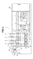
FIG. 1 is a front view of a spinning machine according to an embodiment of the present invention. -
FIG. 2 is a side view of a spinning unit of the spinning machine shown inFIG. 1 . -
FIG. 3 is a cross-sectional view when a yarn monitoring device shown inFIG. 1 is viewed from a yarn path. -
FIG. 4 is an enlarged side view of a suction member and its surrounding when a suction pipe shown inFIG. 2 is at a catching position. -
FIG. 5 is an enlarged front view of the suction member and its surrounding when the suction pipe shown inFIG. 2 is at the catching position. -
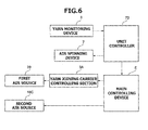
FIG. 6 is a functional block diagram of the spinning machine shown inFIG. 1 . - Exemplary embodiments of the present invention will be explained below with reference to the accompanying drawings. Identical elements will be indicated by like reference symbols in the drawings and duplicate explanation thereof will be omitted. The dimensional ratios of the components in the drawings may not necessarily be same as those in the below explanation.
- As shown in
FIG. 1 , aspinning machine 1 includesplural spinning units 2, a yarn joining carrier (work carrier) 3, a doffing carrier 4, a first end-frame 5A, and a second end-frame 5B. Theplural winding units 2 are arranged side by side in a line. In the following explanation, with respect to a path of a running yarn Y (i.e., yarn path R1), the side on which the yarn Y is formed will be called an upstream side and the side on which the yarn Y is wound will be called a downstream side. - Each
spinning unit 2 forms a yarn Y and winds the yarn Y into a package P. If a yarn breakage or disconnection occurs due to any reason in acertain spinning unit 2, theyarn joining carrier 3 performs a yarn joining operation in thatspinning unit 2. When a package P in acertain spinning unit 2 is fully wound, the doffing carrier 4 doffs that package P and supplies a new bobbin B to thatspinning unit 2. - The first end-
frame 5A houses an air source and/or a suction source and the like. The air source is provided for generating a swirling air current and the like in each component of thespinning unit 2. The suction source is provided for generating a suction current in each component of thespinning unit 2. - The second end-
frame 5B houses a driving motor and the like that supplies a driving force to each component of thespinning unit 2. A main controlling device E, a displaying device D, and one or more input keys K are arranged in the second end-frame 5B. - The main controlling device E centrally manages and controls each component of the
spinning machine 1. The main controlling device (controlling section) E according to the present embodiment controls, for example, an air injecting section (cleaning section) 33 of theyarn joining carrier 3 and an air injecting device (injecting section) 18 of eachspinning unit 2. This control will be explained in detail later. The displaying device D displays information such as information pertaining to the settings and/or the state of thespinning units 2. The operator performs appropriate operation by operating one or more of the input keys K to perform appropriate setting of thespinning units 2. - As shown in
FIGS. 1 and2 , eachspinning unit 2 includes a drafting device 6, an air spinning device (spinning device) 7, ayarn monitoring device 8, anair injecting device 18, atension sensor 9, a yarn accumulating device (yarn pulling device) 11, a waxing device (guiding section) 12, and awinding device 13. These devices are arranged in the running direction of the yarn Y in the stated order from the upstream side. Moreover, these devices are directly or indirectly supported by a machine frame such that the upstream side is located above in the height direction of the machine frame (that is, the downstream side is located below in the height direction of the machine frame). - A not-shown guiding member (guiding section) that regulates a running path of the yarn Y at a position between the
air spinning device 7 and thewinding device 13 is arranged in eachspinning unit 2. For example, the guiding member is arranged at least at one position among a position between theair spinning device 7 and theyarn monitoring device 8, a position between theyarn monitoring device 8 and theyarn accumulating device 11, a position between theyarn accumulating device 11 and thewaxing device 12, and a position immediately downstream of thewaxing device 12. - One
unit controller 70 is arranged for each predetermined number ofspinning units 2 and theunit controller 70 controls the operation of thosespinning units 2. Theunit controller 70 controls the operation of thespinning units 2 based on the information (signals) output from the main controlling device E. - The drafting device 6 drafts a sliver (fiber bundle) S. The drafting device 6 includes a
back roller pair 14, athird roller pair 15, amiddle roller pair 16, and afront roller pair 17 in this order. These components are arranged in the running direction of the sliver S in the stated order from the upstream side. Eachroller pair frame 5B or a driving motor arranged in eachspinning unit 2. Anapron belt 16A is stretched over the top roller of themiddle roller pair 16. Anapron belt 16B is stretched over the bottom roller of themiddle roller pair 16. - The
air spinning device 7 forms the yarn Y by applying a twist to the fiber bundle F, which has been drafted in the drafting device 6, with a swirling air current. Concretely, although not specifically shown in the drawings, theair spinning device 7 includes a spinning chamber, a fiber guiding section, one or more swirling air-current generating nozzles, and a hollow guide shaft. The fiber guiding section guides to the spinning chamber the fiber bundle F supplied from the drafting device 6 arranged upstream. The swirling air-current generating nozzles are arranged around the running path of the fiber bundle F and generate a swirling air current in the spinning chamber. The fiber ends of the fibers constituting the fiber bundle F are reversed and swirled by this swirling air current. The hollow guide shaft guides the yarn Y from the inside of the spinning chamber to the outside of theair spinning device 7. - The
yarn monitoring device 8 is arranged between theair spinning device 7 and theyarn accumulating device 11. Theyarn monitoring device 8 is an optical yarn monitoring device that detects the state of the yarn Y by irradiating light on the running yarn Y. Theyarn monitoring device 8 monitors the state of the running yarn Y to detect presence or absence of a yarn defect in the yarn Y. Upon detecting a yarn defect, theyarn monitoring device 8 transmits a yarn defect detection signal to theunit controller 70. Theyarn monitoring device 8 detects, as the yarn defect, for example, abnormality in the thickness of the yarn Y and/or foreign matter contained in the yarn Y. Theyarn monitoring device 8 also detects yarn breakage and the like. - The
yarn monitoring device 8 will be explained in more detail with reference toFIG. 3 . Theyarn monitoring device 8 includes a holder (yarn passage forming section) 8A and a detecting section. The detecting section includes a light emitting element 81 and alight receiving element 82. - Inside the
holder 8A, which is made of plastic, are arranged the light emitting element 81 and thelight receiving element 82 that detect the state of the yarn Y. Ayarn passage 8C for passing the yarn Y is formed in theholder 8A. Theyarn passage 8C is a groove that extends along the running path of the yarn Y (yarn path R1). If theholder 8A is cut in a plane perpendicular to the yarn path R1, the shape of aninner wall 8B of theyarn passage 8C is formed in a substantially U shape. However, theyarn passage 8C can have other shapes. - The light emitting element 81 can be any appropriate light source such as a light emitting diode (LED). The
light receiving element 82 is a photodiode and converts the intensity of the received light into an electric signal and outputs the electric signal. - The light receiving surface of the
light receiving element 82 constitutes a portion of theinner wall 8B of theyarn passage 8C. Atransparent resin plate 81A is arranged in a portion of theinner wall 8B that faces thelight receiving element 82. The light emitting element 81 is arranged on the opposite side of theyarn passage 8C (inside theholder 8A) with thetransparent plate 81A arranged in between. Thus, the light emitting element 81 and thelight receiving element 82 are arranged facing each other across the yarn path R1. - As shown in
FIGS. 2 and4 , theair injecting device 18 is arranged upstream of theyarn monitoring device 8. Theair injecting device 18 injects compressed air (gas) into theyarn passage 8C of theyarn monitoring device 8 to remove foreign matter such as yarn waste, fly waste, and dust adhering and/or floating inside theyarn passage 8C. Theair injecting device 18 is connected to a second air source 18C (Fig. 6 ) via an airsupply hose pipe 18B, not-shown piping, and the like. The second air source 18C is arranged, for example, in the second end-frame 5B and supplies compressed air to theair injecting device 18 arranged in eachspinning unit 2. - As shown in
FIG. 5 , aninjection port 18A of theair injecting device 18 is arranged so as to overlap the yarn path R1 when viewed from front side. Moreover, as shown inFIG. 4 , theinjection port 18A is oriented obliquely downward toward theyarn passage 8C. With this arrangement, theair injecting device 18 can inject compressed air along theyarn passage 8C. - The
tension sensor 9 measures a tension of the running yarn Y at a position between theair spinning device 7 and theyarn accumulating device 11 and transmits a tension measurement signal representative of the measured tension to theunit controller 70. The waxingdevice 12 applies wax to the yarn Y at a position between theyarn accumulating device 11 and the windingdevice 13. - The
yarn accumulating device 11 eliminates slack in the yarn Y at a position between theair spinning device 7 and the windingdevice 13. Theyarn accumulating device 11 has, for example, the following functions: a function to stably pull the yarn Y from theair spinning device 7; a function to prevent the yarn Y from slackening by accumulating the yarn Y that is being fed-out from theair spinning device 7 during, for example, the yarn joining operation performed by theyarn joining carrier 3; and a function to prevent conveying of variations in the tension of the yarn Y on the downstream side of theyarn accumulating device 11 to theair spinning device 7. - The winding
device 13 forms the package P by winding the yarn Y on the bobbin B. The windingdevice 13 includes acradle arm 21, a windingdrum 22, and atraverse guide 23. - The
cradle arm 21 rotatably supports the bobbin B. Thecradle arm 21 is swingably supported by ashaft 24, and a surface of the bobbin B or a surface of the package P can be pressed with an appropriate pressure against a surface of the windingdrum 22. A not shown driving motor arranged in the second end-frame 5B drives the windingdrums 22 ofplural spinning units 2 all at once. As a result, the bobbin B or the package P in those spinningunits 2 is rotated in the winding direction. The traverse guides 23 of thespinning units 2 are arranged on one common shaft. When the driving motor arranged in the second end-frame 5B causes the shaft to perform a reciprocating movement in a direction parallel to the rotation axis of the windingdrum 22, thetraverse guide 23 traverses the yarn Y within a predetermined width with respect to the rotating bobbin B or the package P. - When the yarn Y is cut in a
certain spinning unit 2 or when a breakage of the yarn Y occurs due to any reason, theyarn joining carrier 3 travels to thatspinning unit 2 to perform a yarn joining operation. As shown inFIG. 2 , theyarn joining carrier 3 includes asuction pipe 31, theair injecting section 33, asuction mouth 38, ayarn joining device 37, afirst air source 39, and a yarn joiningcarrier controlling section 3A. - The
suction pipe 31 catches the yarn Y from theair spinning device 7 and guides the yarn Y to theyarn joining device 37. Thesuction pipe 31 includes a moving member 31B which is rotatably supported on asupport shaft 31A, and a yarn-end catching section 32 that sucks an end of the yarn Y with a suction air current and holds the end. - The moving member 31B is capable of moving the yarn-
end catching section 32 along a running direction V (seeFIG. 1 ), along which the yarn Y runs, between a standby position P1 and a catching position P2 at which the yarn end is caught. The running direction V is the running direction of the yarn Y between theair spinning device 7 and the windingdevice 13 when the spinningmachine 1 is viewed from the front side. - The yarn-
end catching section 32 is fixed to a distal end (an end opposite to the one supported by thesupport shaft 31A) of the moving member 31B. As shown inFIGS. 4 and5 , when the moving member 31B swings and the yarn-end catching section 32 is located at the catching position P2, asuction port 32A of the yarn-end catching section 32 is located facing an exit of theair spinning device 7. The yarn-end catching section 32 is connected to a suction source, which is arranged in the first end-frame 5A, via asuction hose pipe 32B, not-shown piping, and the like. - The
air injecting section 33 moves along the running direction V, and in the course of moving along the running direction V (while moving along the running direction V) injects compressed air (gas) into theyarn passage 8C thereby cleaning any foreign matter adhering and/or floating inside and around theyarn passage 8C. More specifically, as shown inFIG. 2 , theair injecting section 33 is moved along a movement path P0, and while theair injecting section 33 is moving in a region L, as shown inFIG. 4 , the compressed air is injected from theair injecting section 33 into theyarn passage 8C. The region L is the region from where theair injecting section 33 can inject the compressed air into theyarn passage 8C. - A direction in which the compressed air is injected from an
injection port 33A when moving in the region L is offset, as shown inFIG. 5 , by an angle α with respect to an extension direction (the yarn path direction R1) of theyarn passage 8C. This allows cleaning to be effectively performed in the entire width direction (horizontal direction inFIG. 3 ) of theyarn passage 8C. The moving member 31B can be moved continuously or intermittently in the region L. Similarly, theair injecting section 33 can continuously or intermittently inject the compressed air while it is in the region L. - The
air injecting section 33 is attached to the moving member 31B not at the tip portion thereof but at a point slightly shifted toward thesupport shaft 31A from the distal end thereof. When the moving member 31B is swung and located at the catching position P2, theinjection port 33A of theair injecting section 33 is positioned facing theyarn passage 8C in theyarn monitoring device 8. A direction D1 in which theair injecting section 33 injects the compressed air into theyarn passage 8C is different from a direction D2 in which theair injecting device 18 injects the compressed air into theyarn passage 8C. - As shown
FIG. 2 , thesuction mouth 38 is swingably supported by asupport shaft 38A. Thesuction mouth 38 catches the yarn Y from the windingdevice 13 and guides the yarn Y to theyarn joining device 37. Theyarn joining device 37 joins the yarns Y guided thereto. Theyarn joining device 37 can be a splicer that uses compressed air, a piecer that uses a seed yarn, a knotter that mechanically joins the yarns Y, and the like. - The
first air source 39 supplies the compressed air to theair injecting section 33 via an airsupply hose pipe 33B (seeFIG. 4 ). The yarn joiningcarrier controlling section 3A performs various controls in theyarn joining carrier 3. - When the
yarn joining carrier 3 performs the yarn joining operation, the package P is rotated in a direction that is opposite to the direction when the yarn Y is wound (reverse rotation). More specifically, thecradle arm 21 is moved by a not-shown air cylinder such that the package P is separated from the windingdrum 22 and the package P is reversely rotated by a reverserotating roller 36 arranged in theyarn joining carrier 3. - The main controlling device E executes control over the
air injecting section 33 and theair injecting device 18. For example, when formation of the yarn Y in theair spinning device 7 is stopped, that is, when theunit controller 70 determines that an abnormality exists in the yarn Y based on the detection result obtained from theyarn monitoring device 8 and/or thetension sensor 9 or when the yarn Y is disconnected due to any reason, theair injecting section 33 and theair injecting device 18 are operated. Specifically, the main controlling device E operates theair injecting device 18 first and then operates theair injecting section 33. - The doffing carrier 4 performs a bobbin setting operation to prepare for a winding operation of the yarn Y by supplying a bobbin B to the
cradle arm 21, and a doffing operation for removing from the cradle arm 21 a package P that is fully wound. The doffing carrier 4 mainly includes abobbin supplying mechanism 41, asuction pipe 43, apackage transporting mechanism 47, and a doffingcarrier controlling section 4A. - The
bobbin supplying mechanism 41 receives a new bobbin B from a bobbin storing section, and while holding the bobbin B, swings to supply the held bobbin B to thecradle arm 21. Thepackage transporting mechanism 47 receives the fully wound package P from thecradle arm 21 and transports the package P to a discharging section (for example, a conveyor belt arranged between a travelling path of the doffing carrier 4 and plural spinning units 2). Thesuction pipe 43 sucks and catches a yarn end of the yarn Y formed in theair spinning device 7 and guides the caught yarn Y to the windingdevice 13. The doffingcarrier controlling section 4A performs various controls on the doffing carrier 4. - One of the characteristic features of the present embodiment will be explained next while referring to
FIG. 6 . That is, a cleaning operation performed by theair injecting device 18 and theair injecting section 33 for cleaning theyarn passage 8C of theyarn monitoring device 8 will be explained. Upon determining based on the detection result obtained from theyarn monitoring device 8 and/or thetension sensor 9 that there exists an abnormality in the yarn Y, theunit controller 70 causes the yarn Y in thespinning unit 2 to be disconnected. Specifically, theunit controller 70 stops the supply of air to theair spinning device 7 thereby suspending the formation of the yarn Y. - Then, the
unit controller 70 transmits the yarn defect detection signal to the main controlling device E. The main controlling device E, having received the yarn defect detection signal, transmits a control signal to the yarn joiningcarrier controlling section 3A of theyarn joining carrier 3. Theyarn joining carrier 3, having received the control signal, travels to thetarget spinning unit 2. The main controlling device E controls, simultaneously with controlling the travelling of theyarn joining carrier 3, the second air source 18C to start injection of the compressed air into theyarn passage 8C by theair injecting device 18. - When the
yarn joining carrier 3 has reached thetarget spinning unit 2, the main controlling device E controls the second air source 18C to stop the injection of the compressed air from theair injecting device 18. Next, the main controlling device E causes theyarn joining carrier 3 to start the yarn joining operation via the yarn joiningcarrier controlling section 3A. That is, the main controlling device E causes the yarn joiningcarrier controlling section 3A to swing thesuction pipe 31 to the catching position P2 (seeFIG. 4 ). Simultaneously with this, the main controlling device E controls thefirst air source 39 such that theair injecting section 33 can inject the compressed air into theyarn passage 8C while theair injecting section 33 is moving along the running direction V. Specifically, as shown inFIG. 4 , the main controlling device E controls thefirst air source 39 such that theair injecting section 33 injects the compressed air into theyarn passage 8C while theair injecting section 33 is moving in the region L. In other words, the main controlling device E executes control so that theair injecting section 33 starts the injection of the compressed air at the instant theair injecting section 33 enters the region L and stops the injection of the compressed air at the instant theair injecting section 33 exits from the region L. - When the
yarn joining carrier 3 completes the yarn joining operation, theunit controller 70 again operates theair spinning device 7 to cause thespinning unit 2 to resume the winding of the yarn Y into the package P. - The actions of and advantageous effects provided by the spinning
machine 1 according to the above embodiments will be explained now. In the spinningmachine 1 according to the above embodiments, as shown inFIG. 2 , because theair injecting section 33 cleans theyarn monitoring device 8 while moving along the running direction V, a wider area of theyarn monitoring device 8 can be cleaned. As a result, the foreign matter can be removed more effectively. Moreover, in the spinningmachine 1 according to the above embodiments, theair injecting section 33 cleans theyarn passage 8C while moving along the running direction V that extends along the yarn path R1. As a result, theentire yarn passage 8C can be cleaned. - In the spinning
machine 1 according to the above embodiments, the foreign matter adhering and/or floating inside theyarn passage 8C can be removed with theair injecting device 18 that is arranged separately from theair injecting section 33. Because the compressed air is injected from theair injecting section 33 and theair injecting device 18 from mutually different directions, the foreign matter can be removed from a wider area. In the spinningmachine 1 according to the above embodiments, the foreign matter adhering and/or floating inside theyarn passage 8C is removed first and then the foreign matter around theyarn passage 8C is removed. Accordingly, because the foreign matter and the like are prevented from being pushed into the inside of theyarn passage 8C by the action of theair injecting section 33, cleaning can be performed effectively. - In the spinning
machine 1 according to the above embodiments, because theair injecting section 33 is provided with respect to the moving member 31B that moves the yarn-end catching section 32, it is not necessary to provide a dedicated moving member to move theair injecting section 33. In the spinningmachine 1 according to the above embodiments, the movement path P0 along which the yarn-end catching section 32 is moved from the standby position P1 to the catching position P2 is set to pass near theyarn monitoring device 8. Therefore, theair injecting section 33 can be accurately moved to a position facing theyarn monitoring device 8 that is to be cleaned. - In the spinning
machine 1 according to the above embodiments, theair injecting section 33 injects the compressed air from the dedicatedfirst air source 39 arranged in theyarn joining carrier 3. This arrangement enables the compressed air to be injected forcefully as compared to a case where the compressed air is injected from an air source that is shared byplural spinning units 2. - In the spinning
machine 1 according to the above embodiments, theyarn monitoring device 8 is arranged between theair spinning device 7 and theyarn accumulating device 11. In this arrangement, the foreign matter generated in theair spinning device 7, such as fiber waste (oil and dye powder depending on the fiber bundle), can easily adhere and/or float inside and around theyarn passage 8C of theyarn monitoring device 8. In the spinningmachine 1 having such a configuration, when theair injecting section 33 is moved along the running direction and cleaning of theyarn monitoring device 8 is performed in the course of such a movement along the running direction, the foreign matter can be removed effectively. - Embodiments of the present invention have been explained above; however, the present invention is not to be limitedly interpreted to the above-explained embodiments.
- The above embodiments explain the example of the spinning
machine 1 in which theair injecting device 18 that injects the compressed air into theyarn passage 8C of theyarn monitoring device 8 is arranged separately from theair injecting section 33; however, the present invention is not limited to this configuration. That is, even if theair injecting device 18 is omitted, the cleaning of theyarn monitoring device 8 can be performed while moving theair injecting section 33 along the yarn path R1 allowing a wider area of theyarn monitoring device 8 to be cleaned. Moreover, theair injecting device 18 can be omitted from thespinning unit 2, and instead, an injecting section that injects the compressed air into theyarn passage 8C can be arranged in theyarn monitoring device 8. - The above embodiments explain the example of the spinning
machine 1 in which theair injecting section 33 that injects the compressed air inside and around theyarn passage 8C is arranged in theyarn joining carrier 3; however, the present invention is not limited to this configuration. For example, an air injecting section that can inject the compressed air inside and around theyarn passage 8C can be arranged in eachspinning unit 2 instead of arranging the air injecting section in theyarn joining carrier 3. That is, a moving member that can move the air injecting section along the yarn path R1 between a first position and a second position, which is different from the first position, can be arranged in eachspinning unit 2. Moreover, theyarn joining carrier 3 can be omitted, and instead, a yarn joining device and a suction pipe (moving member), which includes a yarn-end catching section that catches a yarn end and an air injecting section (cleaning section) that performs cleaning of theyarn monitoring device 8, can be arranged in eachspinning unit 2. If this configuration is adopted, the air source that supplies the compressed air to the air injecting section can be arranged in eachspinning unit 2, or can be arranged commonly for a predetermined number of thespinning units 2. - The above embodiments explain the example of the spinning
machine 1 that includes the doffing carrier 4; however, the present invention is not limited to this configuration. That is, the doffing carrier 4 in the spinningmachine 1 can be omitted. Alternatively, an air injecting section that injects compressed air inside and around theyarn passage 8C can be arranged in the doffing carrier (work carrier) 4. That is, a cleaning section, which injects compressed air (gas) into theyarn passage 8C while moving along the yarn path R1 to clean the foreign matter adhering and/or floating inside and around theyarn passage 8C, can be provided with respect to a suction pipe (moving member and yarn-end catching section) arranged in the doffing carrier 4. One air injecting section can be arranged in each of theyarn joining carrier 3 and the doffing carrier 4. - The above embodiments explain the example of the spinning
machine 1 that includes, as a cleaning section that performs cleaning inside and around theyarn passage 8C while moving along the yarn path R1 along which the yarn Y runs, theair injecting section 33 that injects the compressed air; however, the present invention is not limited to this configuration. For example, as a cleaning section that performs cleaning inside and around theyarn passage 8C, a suction member that sucks the foreign matter may be provided, or a wiping section that wipes off the foreign matter adhering inside and around theyarn passage 8C may be provided. - The above embodiments explain the example of the spinning
machine 1 in which the main controlling device E operates theair injecting device 18 first and then operates theair injecting section 33; however, the present invention is not limited to this configuration. For example, the main controlling device E can operate theair injecting device 18 first and then operate theair injecting section 33. Moreover, at least a part of a time period in which theair injecting device 18 is operating and a time period in which theair injecting section 33 is operating can have an overlap. Specifically, theair injecting device 18 and theair injecting section 33 can be operated simultaneously for a certain length of time. Moreover, injection of the compressed air from one among theair injecting device 18 and theair injecting section 33 can be started after starting injection of the compressed air from the other one, and the injection of the compressed air from one among theair injecting device 18 and theair injecting section 33 can be stopped earlier than the other one. - The above embodiments explain the example of the spinning
machine 1 in which theyarn monitoring device 8 is arranged between theair spinning device 7 and the yarn accumulating device (yarn pulling device) 11; however, the present invention is not limited to this configuration. The present invention can be applied to a spinning machine in which, for example, theyarn monitoring device 8 is arranged downstream of theyarn accumulating device 11. - In the spinning
machine 1 according to the above embodiments, theair injecting section 33 performs the cleaning of theyarn monitoring device 8; however, the present invention is not limited to this configuration. For example, theair injecting section 33 can perform cleaning of, in addition to performing the cleaning of theyarn monitoring device 8 or in place of performing the cleaning of theyarn monitoring device 8, the guiding member and/or thewaxing device 12 while moving along the running direction V. - The structure of the
yarn monitoring device 8 is not limited to that explained in the above embodiments. For example, one detecting section including one light emitting element 81 and onelight receiving element 82 is arranged in the running direction of the yarn Y (one-step formation) in the above embodiments; however, two such detecting sections can be arranged in the running direction of the yarn Y (two-step formation). Moreover, the detecting section in the above embodiments includes one light emitting element 81 and onelight receiving element 82; however, the light emitting element and the receiving element can be arranged in desired numbers. The detecting section in the above embodiment is an optical detecting section; however, theyarn monitoring device 8 can include, for example, other types of detecting sections such as an electrostatic capacitance type detecting section. - The above embodiments explain the example of the spinning
machine 1 in which, with respect to the height direction of the machine frame, the yarn Y supplied from the upper side is wound on the lower side. However, in an alternative configuration, the yarn Y supplied from the lower side can be wound on the upper side. When such a configuration is adopted, an air injecting section that injects the compressed air inside and around theyarn passage 8C can be arranged in a yarn joining carrier that runs in an upper part of the machine frame. - The air spinning device can include a needle that is held by the fiber guiding section so as to protrude in the spinning chamber to prevent the twist of the fiber bundle from being conveyed to the upstream side of the air spinning device. In the air spinning device, instead of arranging such a needle, the end on the downstream side of the fiber guiding section can be used to prevent the twist of the fiber bundle from being conveyed to the upstream side of the air spinning device. Furthermore, in the air spinning device, instead of the above configuration, a pair of air jet nozzles that twist the yarn Y in mutually opposite directions can be arranged.
- The
suction pipe 31, in addition to having a function to catch the yarn end by sucking, can include a twisting member that twists the caught yarn end by the action of air current. If this configuration is adopted, three hose pipes are externally connected to the suction pipe. - In the
spinning unit 2, theyarn accumulating device 11 is used to pull the yarn Y from theair spinning device 7; however, a delivery roller and a nip roller can be used to pull the yarn Y from theair spinning device 7. If this configuration is adopted, theyarn accumulating device 11 can be arranged downstream of the delivery roller and the nip roller. If the yarn Y is pulled from theair spinning device 7 by using the delivery roller and the nip roller, a slack tube that absorbs the slack in the yarn Y by using suction current, a mechanical compensator, or the like, can be arranged instead of theyarn accumulating device 11. As long as theyarn monitoring device 8 is arranged downstream of theair spinning device 7, it can be arranged upstream or downstream of the delivery roller and the nip roller. - In the spinning
machine 1, at least one of the bottom rollers of the drafting device 6 and thetraverse guide 23 are driven by the driving force from the second end-frame 5B (that is, the driving source is shared by plural spinning units 2). However, each component of the spinning unit 2 (for example, the drafting device, the spinning device, the winding device, and the like) can be driven independently in eachspinning unit 2. - The
tension sensor 9 can be arranged upstream of theyarn monitoring device 8 in the running direction of the yarn Y. Oneunit controller 70 can be arranged for eachspinning unit 2. Moreover, in thespinning unit 2, the waxingdevice 12, thetension sensor 9, and theyarn monitoring device 8 can be omitted. - In
FIG. 1 , the spinningmachine 1 is shown to wind a cheese-shaped package P; however, it is possible to wind a cone-shaped package. Slack occurs in the yarn when traversing the yarn for winding the cone-shaped package; however, such slack can be absorbed by theyarn accumulating device 11. - According to an aspect of the present invention, a spinning machine includes a spinning device that forms a yarn by applying twist to a fiber bundle; a winding device that forms a package by winding the yarn formed by the spinning device; a yarn monitoring device that monitors a state of the yarn based on information detected in a detecting section that detects the state of the yarn running between the spinning device and the winding device; a guiding section that guides the yarn running from the spinning device to the winding device; and a cleaning section that is movable along a running direction of the yarn and that, in a state in which the formation of the yarn by the spinning device is stopped, cleans at least one of the yarn monitoring device and the guiding section while moving along the running direction.
- The scope of the term "moving along running direction" is not limited to movement in a direction that is parallel to the running direction but also includes movement in a direction that is little offset from the direction that is parallel to the running direction. Moreover, the scope of the term "moving along the running direction" is not limited to movement from the spinning device toward the winding device but also includes movement from the winding device toward the spinning device. In the spinning machine having the above configuration, because the cleaning section cleans the yarn monitoring device while moving along the running direction, a wider area of the yarn monitoring device can be cleaned. As a result, the foreign matter can be removed more effectively.
- In the above spinning machine, the yarn monitoring device includes a yarn passage forming section that constitutes a yarn passage through which the yarn runs, and the detecting section detects the yarn running in the yarn passage.
- In the spinning machine having the above configuration, because the cleaning section cleans the yarn monitoring device while moving along the running direction with respect to the yarn passage that extends in the running direction, the entire yarn passage can be cleaned.
- The above spinning machine further includes an injecting section, arranged separately from the cleaning section, that injects gas into the yarn passage; and a controlling section that operates the cleaning section and the injecting section while the formation of the yarn by the spinning device is stopped.
- In the spinning machine having the above configuration, the foreign matter adhering and/or floating inside the yarn passage can be removed with the injecting section while the foreign matter adhering and/or floating inside or around the yarn passage can be removed with the cleaning section. As a result, the foreign matter can be removed more effectively.
- In the above spinning machine, the cleaning section cleans the yarn monitoring device by injecting gas into the yarn passage, and the injecting section injects gas in a direction that is different from a direction in which the cleaning section injects gas.
- In the spinning machine having the above configuration, because gas is injected from mutually different directions by the cleaning section and the injecting section, the foreign matter can be removed from a wider area. As a result, the foreign matter can be removed more effectively.
- In the above spinning machine, the controlling section operates the cleaning section after operating the injecting section.
- In the spinning machine having the above configuration, the foreign matter adhering and/or floating inside the yarn passage is removed first and then the foreign matter around the yarn passage is removed. Accordingly, for example, the foreign matter and the like are prevented from being pushed into the inside of the yarn passage by the action of the cleaning section and the like, and cleaning can be performed effectively.
- The above spinning machine further includes a yarn-end catching section that catches an end of the yarn that is formed by the spinning device; and a moving member capable of moving the yarn-end catching section along the running direction between a standby position and a catching position at which an end of the yarn is caught. The cleaning section is provided with respect to the moving member.
- In the spinning machine having the above configuration, because the cleaning section is provided with respect to the moving member that moves the yarn-end catching section, the configuration of the spinning machine can be made simple.
- The above spinning machine further includes plural winding units each including the spinning device, the yarn monitoring device, and the winding device; and a work carrier that is movable with respect to at least a predetermined number of the winding units among the plural winding units. The work carrier includes the moving member and a gas source that supplies gas to the cleaning section.
- In the spinning machine having the above configuration, gas can be injected from a dedicated gas source arranged in the work carrier. Accordingly, gas can be injected forcefully as compared to a case where gas is injected from a gas source that is shared by plural spinning units. As a result, the foreign matter can be removed more effectively.
- The above spinning machine further includes a yarn pulling device that pulls the yarn formed in the spinning device. The yarn monitoring device is arranged between the spinning device and the yarn pulling device.
- In the spinning machine having the above configuration, the foreign matter such as fiber waste generated in the spinning device can easily adhere and/or float inside and around the yarn passage arranged in the yarn monitoring device. In the spinning device having the above configuration, however, when the cleaning section is caused to clean the yarn monitoring device while moving along the running direction, the foreign matter can be removed effectively.
- According to another aspect of the present invention, a work carrier for use in a spinning machine that includes a yarn monitoring device that monitors a state of a yarn formed by a spinning device includes a yarn-end catching section that catches an end of the yarn; a moving member capable of moving the yarn-end catching section along a running direction of the yarn between a standby position and a catching position at which the end of the yarn is caught; and a cleaning section that is provided with respect to the moving member and that cleans the yarn monitoring device while moving along the running direction.
- In the work carrier having the above configuration, because the cleaning section cleans the yarn monitoring device while moving along the running direction, a wider area of the yarn monitoring device can be cleaned. As a result, the foreign matter can be removed more effectively.
Claims (12)
- A spinning machine (1) comprising:a spinning device (7) adapted to form a yarn (Y) by applying twist to a fiber bundle (F);a winding device (13) adapted to form a package (P) by winding the yarn (Y) formed by the spinning device (7);a yarn monitoring device (8) adapted to monitor a state of the yarn (Y) based on information detected in a detecting section (81, 82) adapted to detect the state of the yarn (Y) running between the spinning device (7) and the winding device (13);a guiding section (12) adapted to guide the yarn (Y) running from the spinning device (7) to the winding device (13); characterized bya cleaning section (33) arranged movable along a running direction of the yarn (Y) and adapted to, in a state in which formation of the yarn (Y) by the spinning device (7) is stopped, clean at least one of the yarn monitoring device (8) and the guiding section (12) while moving along the running direction.
- The spinning machine (1) as claimed in Claim 1, characterized in that the yarn monitoring device (8) includes a yarn passage forming section (8A) adapted to constitute a yarn passage (8C) through which the yarn (Y) runs, and
the detecting section (81, 82) is adapted to detect the yarn (Y) running in the yarn passage (8C). - The spinning machine (1) as claimed in Claim 2, further characterized by:an injecting section (18), arranged separately from the cleaning section (33), adapted to inject gas into the yarn passage (8C); anda controlling section (E) adapted to operate the cleaning section (33) and the injecting section (18) while the formation of the yarn (Y) by the spinning device (7) is stopped.
- The spinning machine (1) as claimed in Claim 3, characterized in that the cleaning section (33) is adapted to clean the yarn monitoring device (8) by injecting gas into the yarn passage (8C), and
the injecting section (18) is adapted to inject gas in a direction that is different from a direction in which the cleaning section (33) injects gas. - The spinning machine (1) as claimed in Claim 3 or 4, characterized in that the controlling section (E) is adapted to operate the cleaning section (33) after operating the injecting section (18).
- The spinning machine (1) as claimed in any one of Claims 1 to 5, characterized in that the guiding section is adapted to regulate a running path (R1) of the yarn (Y) between the spinning device (7) and the winding device (13) and to guide the yarn (Y).
- The spinning machine (1) as claimed in any one of Claims 1 to 6, characterized in that the guiding section is a waxing device (12) adapted to apply wax to the yarn (Y) at a position between the spinning device (7) and the winding device (13).
- The spinning machine (1) as claimed in any one of Claims 1 to 5, further characterized by:a yarn-end catching section (32) adapted to catch an end of the yarn (Y) that is formed by the spinning device (7); anda moving member (31B) adapted to be capable of moving the yarn-end catching section (32) along the running direction between a standby position and a catching position at which an end of the yarn (Y) is caught,wherein the cleaning section is provided with respect to the moving member.
- The spinning machine (1) as claimed in Claim 8, characterized in that the cleaning section (33) is adapted to clean at least one of the yarn monitoring device (8) and the guiding section (12) while the moving member (31B) is moving the yarn-end catching section (32) from the standby position to the catching position.
- The spinning machine (1) as claimed in Claim 8 or 9, further characterized by:plural winding units (2) each including the spinning device (7), the yarn monitoring device (8), and the winding device (13); anda work carrier (3; 4) adapted to be movable with respect to at least a predetermined number of the winding units (2) among the plural winding units (2),wherein the work carrier (3; 4) includes the moving member (31B) and a gas source (39) adapted to supply gas to the cleaning section (33).
- The spinning machine (1) as claimed in any one of Claims 1 to 10, further characterized by a yarn pulling device (11) adapted to pull the yarn (Y) formed in the spinning device (7),
wherein the yarn monitoring device (8) is arranged between the spinning device (7) and the yarn pulling device (11). - A work carrier (3; 4) for use in a spinning machine (1) that includes a yarn monitoring device (8) adapted to monitor a state of a yarn (Y) formed by a spinning device (7), the work carrier (3; 4) characterized by:a yarn-end catching section (32) adapted to catch an end of the yarn (Y);a moving member (31B) adapted to be capable of moving the yarn-end catching section (32) along a running direction of the yarn (Y) between a standby position and a catching position at which the end of the yarn (Y) is caught; anda cleaning section (33) provided with respect to the moving member (31B) and adapted to clean the yarn monitoring device (8) while moving along the running direction.
Applications Claiming Priority (1)
| Application Number | Priority Date | Filing Date | Title |
|---|---|---|---|
| JP2014226166A JP2016089302A (en) | 2014-11-06 | 2014-11-06 | Spinning machine and working carriage |
Publications (1)
| Publication Number | Publication Date |
|---|---|
| EP3018240A1 true EP3018240A1 (en) | 2016-05-11 |
Family
ID=54266450
Family Applications (1)
| Application Number | Title | Priority Date | Filing Date |
|---|---|---|---|
| EP15188635.5A Withdrawn EP3018240A1 (en) | 2014-11-06 | 2015-10-06 | Spinning machine and work carrier |
Country Status (3)
| Country | Link |
|---|---|
| EP (1) | EP3018240A1 (en) |
| JP (1) | JP2016089302A (en) |
| CN (1) | CN105586671A (en) |
Cited By (1)
| Publication number | Priority date | Publication date | Assignee | Title |
|---|---|---|---|---|
| WO2020254978A1 (en) * | 2019-06-19 | 2020-12-24 | Maschinenfabrik Rieter Ag | Suction device for a service robot for a yarn manufacturing textile machine, a service robot, and a textile machine |
Citations (5)
| Publication number | Priority date | Publication date | Assignee | Title |
|---|---|---|---|---|
| EP0405367A1 (en) * | 1989-06-28 | 1991-01-02 | Zinser Textilmaschinen GmbH | Method for maintaining the fail-safe working of a service tender in spinning machine |
| JPH0421577U (en) | 1990-06-08 | 1992-02-24 | ||
| JP2000327226A (en) | 1999-05-17 | 2000-11-28 | Murata Mach Ltd | Sensitivity adjustment device for yarn clearer |
| EP2657382A2 (en) * | 2012-04-27 | 2013-10-30 | Murata Machinery, Ltd. | Yarn monitoring device and yarn winding machine including the same |
| EP2671982A1 (en) * | 2012-06-08 | 2013-12-11 | Murata Machinery, Ltd. | Spinning machine |
Family Cites Families (2)
| Publication number | Priority date | Publication date | Assignee | Title |
|---|---|---|---|---|
| JP5029146B2 (en) * | 2007-06-04 | 2012-09-19 | 村田機械株式会社 | Spinning equipment |
| JP2013253353A (en) * | 2012-06-08 | 2013-12-19 | Murata Mach Ltd | Spinning machine |
-
2014
- 2014-11-06 JP JP2014226166A patent/JP2016089302A/en active Pending
-
2015
- 2015-10-06 EP EP15188635.5A patent/EP3018240A1/en not_active Withdrawn
- 2015-10-12 CN CN201510659103.3A patent/CN105586671A/en active Pending
Patent Citations (6)
| Publication number | Priority date | Publication date | Assignee | Title |
|---|---|---|---|---|
| EP0405367A1 (en) * | 1989-06-28 | 1991-01-02 | Zinser Textilmaschinen GmbH | Method for maintaining the fail-safe working of a service tender in spinning machine |
| JPH0421577U (en) | 1990-06-08 | 1992-02-24 | ||
| JP2000327226A (en) | 1999-05-17 | 2000-11-28 | Murata Mach Ltd | Sensitivity adjustment device for yarn clearer |
| EP2657382A2 (en) * | 2012-04-27 | 2013-10-30 | Murata Machinery, Ltd. | Yarn monitoring device and yarn winding machine including the same |
| JP2013230908A (en) | 2012-04-27 | 2013-11-14 | Murata Machinery Ltd | Yarn monitoring device and yarn winding machine including the same |
| EP2671982A1 (en) * | 2012-06-08 | 2013-12-11 | Murata Machinery, Ltd. | Spinning machine |
Cited By (1)
| Publication number | Priority date | Publication date | Assignee | Title |
|---|---|---|---|---|
| WO2020254978A1 (en) * | 2019-06-19 | 2020-12-24 | Maschinenfabrik Rieter Ag | Suction device for a service robot for a yarn manufacturing textile machine, a service robot, and a textile machine |
Also Published As
| Publication number | Publication date |
|---|---|
| CN105586671A (en) | 2016-05-18 |
| JP2016089302A (en) | 2016-05-23 |
Similar Documents
| Publication | Publication Date | Title |
|---|---|---|
| EP2876192B1 (en) | Air-jet spinning device and spinning machine | |
| EP2727870B1 (en) | Yarn winding machine and yarn winding method | |
| EP2573017B1 (en) | Yarn winding unit, yarn winding apparatus and spinning machine | |
| CN110158207B (en) | Air spinning machine and air spinning method | |
| JP2013067475A (en) | Yarn winding machine and yarn winding unit | |
| EP3025995B1 (en) | Yarn winding machine | |
| EP2573223A2 (en) | Pneumatic spinning device, spinning unit, spinning machine, and pneumatic spinning method | |
| EP2657382B1 (en) | Yarn monitoring device and yarn winding machine including the same | |
| CN108691046B (en) | Spinning machine | |
| EP3040458B1 (en) | Core yarn supplying device, spinning machine, and method of supplying core yarn | |
| JP2014125714A (en) | Spinning machine | |
| CN205474168U (en) | Cleaning device , drafting arrangement and spinning machine | |
| JP2013067474A (en) | Yarn winding machine and yarn winding unit | |
| JP2019026980A (en) | Air spinning machine | |
| EP3095742A1 (en) | Yarn winding machine | |
| EP2862826A1 (en) | Yarn winding machine | |
| EP2985371B1 (en) | Spinning machine | |
| JP2016166067A (en) | Ending device, spinning machine and automatic winder | |
| EP3421650A1 (en) | Air-jet spinning machine | |
| CN115961390A (en) | Spinning mechanism | |
| JP2016089302A (en) | Spinning machine and working carriage | |
| EP2966199B1 (en) | Spinning machine and spinning method | |
| JP2019007109A (en) | Air spinning machine | |
| JP2022085989A (en) | Spinning machine | |
| JP2025047900A (en) | Spinning machine |
Legal Events
| Date | Code | Title | Description |
|---|---|---|---|
| PUAI | Public reference made under article 153(3) epc to a published international application that has entered the european phase |
Free format text: ORIGINAL CODE: 0009012 |
|
| AK | Designated contracting states |
Kind code of ref document: A1 Designated state(s): AL AT BE BG CH CY CZ DE DK EE ES FI FR GB GR HR HU IE IS IT LI LT LU LV MC MK MT NL NO PL PT RO RS SE SI SK SM TR |
|
| AX | Request for extension of the european patent |
Extension state: BA ME |
|
| 17P | Request for examination filed |
Effective date: 20160517 |
|
| RBV | Designated contracting states (corrected) |
Designated state(s): AL AT BE BG CH CY CZ DE DK EE ES FI FR GB GR HR HU IE IS IT LI LT LU LV MC MK MT NL NO PL PT RO RS SE SI SK SM TR |
|
| 17Q | First examination report despatched |
Effective date: 20161220 |
|
| STAA | Information on the status of an ep patent application or granted ep patent |
Free format text: STATUS: THE APPLICATION HAS BEEN WITHDRAWN |
|
| 18W | Application withdrawn |
Effective date: 20180808 |