EP3018104A1 - Ballast water treatment apparatus and method for ship using forward osmosis process - Google Patents
Ballast water treatment apparatus and method for ship using forward osmosis process Download PDFInfo
- Publication number
- EP3018104A1 EP3018104A1 EP15178173.9A EP15178173A EP3018104A1 EP 3018104 A1 EP3018104 A1 EP 3018104A1 EP 15178173 A EP15178173 A EP 15178173A EP 3018104 A1 EP3018104 A1 EP 3018104A1
- Authority
- EP
- European Patent Office
- Prior art keywords
- water
- draw solution
- ship
- treatment
- ballast water
- Prior art date
- Legal status (The legal status is an assumption and is not a legal conclusion. Google has not performed a legal analysis and makes no representation as to the accuracy of the status listed.)
- Granted
Links
Images



Classifications
-
- B—PERFORMING OPERATIONS; TRANSPORTING
- B63—SHIPS OR OTHER WATERBORNE VESSELS; RELATED EQUIPMENT
- B63J—AUXILIARIES ON VESSELS
- B63J4/00—Arrangements of installations for treating ballast water, waste water, sewage, sludge, or refuse, or for preventing environmental pollution not otherwise provided for
- B63J4/002—Arrangements of installations for treating ballast water, waste water, sewage, sludge, or refuse, or for preventing environmental pollution not otherwise provided for for treating ballast water
-
- B—PERFORMING OPERATIONS; TRANSPORTING
- B01—PHYSICAL OR CHEMICAL PROCESSES OR APPARATUS IN GENERAL
- B01D—SEPARATION
- B01D61/00—Processes of separation using semi-permeable membranes, e.g. dialysis, osmosis or ultrafiltration; Apparatus, accessories or auxiliary operations specially adapted therefor
- B01D61/002—Forward osmosis or direct osmosis
- B01D61/0022—Apparatus therefor
-
- B—PERFORMING OPERATIONS; TRANSPORTING
- B01—PHYSICAL OR CHEMICAL PROCESSES OR APPARATUS IN GENERAL
- B01D—SEPARATION
- B01D61/00—Processes of separation using semi-permeable membranes, e.g. dialysis, osmosis or ultrafiltration; Apparatus, accessories or auxiliary operations specially adapted therefor
- B01D61/002—Forward osmosis or direct osmosis
- B01D61/005—Osmotic agents; Draw solutions
-
- C—CHEMISTRY; METALLURGY
- C02—TREATMENT OF WATER, WASTE WATER, SEWAGE, OR SLUDGE
- C02F—TREATMENT OF WATER, WASTE WATER, SEWAGE, OR SLUDGE
- C02F1/00—Treatment of water, waste water, or sewage
- C02F1/44—Treatment of water, waste water, or sewage by dialysis, osmosis or reverse osmosis
- C02F1/445—Treatment of water, waste water, or sewage by dialysis, osmosis or reverse osmosis by forward osmosis
-
- B—PERFORMING OPERATIONS; TRANSPORTING
- B01—PHYSICAL OR CHEMICAL PROCESSES OR APPARATUS IN GENERAL
- B01D—SEPARATION
- B01D2311/00—Details relating to membrane separation process operations and control
- B01D2311/04—Specific process operations in the feed stream; Feed pretreatment
-
- B—PERFORMING OPERATIONS; TRANSPORTING
- B01—PHYSICAL OR CHEMICAL PROCESSES OR APPARATUS IN GENERAL
- B01D—SEPARATION
- B01D2311/00—Details relating to membrane separation process operations and control
- B01D2311/26—Further operations combined with membrane separation processes
- B01D2311/2649—Filtration
-
- B—PERFORMING OPERATIONS; TRANSPORTING
- B01—PHYSICAL OR CHEMICAL PROCESSES OR APPARATUS IN GENERAL
- B01D—SEPARATION
- B01D2313/00—Details relating to membrane modules or apparatus
- B01D2313/26—Specific gas distributors or gas intakes
-
- B—PERFORMING OPERATIONS; TRANSPORTING
- B01—PHYSICAL OR CHEMICAL PROCESSES OR APPARATUS IN GENERAL
- B01D—SEPARATION
- B01D2313/00—Details relating to membrane modules or apparatus
- B01D2313/36—Energy sources
-
- B—PERFORMING OPERATIONS; TRANSPORTING
- B01—PHYSICAL OR CHEMICAL PROCESSES OR APPARATUS IN GENERAL
- B01D—SEPARATION
- B01D2315/00—Details relating to the membrane module operation
- B01D2315/06—Submerged-type; Immersion type
-
- C—CHEMISTRY; METALLURGY
- C02—TREATMENT OF WATER, WASTE WATER, SEWAGE, OR SLUDGE
- C02F—TREATMENT OF WATER, WASTE WATER, SEWAGE, OR SLUDGE
- C02F1/00—Treatment of water, waste water, or sewage
- C02F1/001—Processes for the treatment of water whereby the filtration technique is of importance
-
- C—CHEMISTRY; METALLURGY
- C02—TREATMENT OF WATER, WASTE WATER, SEWAGE, OR SLUDGE
- C02F—TREATMENT OF WATER, WASTE WATER, SEWAGE, OR SLUDGE
- C02F2103/00—Nature of the water, waste water, sewage or sludge to be treated
- C02F2103/008—Originating from marine vessels, ships and boats, e.g. bilge water or ballast water
-
- Y—GENERAL TAGGING OF NEW TECHNOLOGICAL DEVELOPMENTS; GENERAL TAGGING OF CROSS-SECTIONAL TECHNOLOGIES SPANNING OVER SEVERAL SECTIONS OF THE IPC; TECHNICAL SUBJECTS COVERED BY FORMER USPC CROSS-REFERENCE ART COLLECTIONS [XRACs] AND DIGESTS
- Y02—TECHNOLOGIES OR APPLICATIONS FOR MITIGATION OR ADAPTATION AGAINST CLIMATE CHANGE
- Y02A—TECHNOLOGIES FOR ADAPTATION TO CLIMATE CHANGE
- Y02A20/00—Water conservation; Efficient water supply; Efficient water use
- Y02A20/124—Water desalination
- Y02A20/131—Reverse-osmosis
Definitions
- Exemplary embodiments of the present invention relate to a ballast water treatment apparatus and method for a ship using a forward osmosis process, and more particularly, to a ballast water treatment apparatus and method for a ship using a forward osmosis process, capable of treating and producing ballast water in a ship using a forward osmosis process so as to supply eco-friendly ballast water to the ship in a low-cost and high efficient manner.
- Ballast water in a ship is sea water filled within the ship, and serves to improve safety of the ship by lowering a center of gravity of the ship or adjusting horizontal balance of the ship according to a cargo amount.
- the ballast water lowers the center of gravity of the ship to prevent propulsion from decreasing due to rising of a propeller near to a water surface when the center of gravity of the ship becomes high and to prevent fatigue failure caused by impact with the water surface when the propeller is rotated, thereby enabling the ship to be effectively operated.
- ballast water in the ship is an essential condition in navigation.
- sea water collected from a loading place of cargoes is used as the ballast water and the used ballast water is discharged to an unloading place of cargoes, thereby allowing marine organisms to be artificially moved.
- the ballast water is one of the causes of marine pollution. Accordingly, in order to resolve these problems, "a Ballast Water Management Act (2004)" is internationally adopted and a ballast water treatment system will be defined to be obligatorily installed in ships from all over the world from 2017.
- ballast water in a ship is conventionally treated by a chemical treatment method of injecting a sterilization component such as ozone or chlorine into collected sea water, a method of electrically treating collected sea water, a physical treatment method of simply filtering collected sea water, or the like.
- a sterilization component such as ozone or chlorine
- a physical treatment method of simply filtering collected sea water or the like.
- the treated ballast water is exposed to chemicals in such a conventional ballast water treatment method, a marine ecosystem is contaminated when the ballast water is discharged after being used.
- a method of having little influence on the marine ecosystem is costly. Therefore, it is necessary to develop an eco-friendly ballast water treatment system for a ship, capable of treating and supplying ballast water in a ship in a low-cost and high efficient manner and having little influence on a marine ecosystem.
- Patent Document Korean Patent Publication No. 10-1204879 (November 20, 2012 )
- An object of the present invention is to provide a ballast water treatment apparatus and method for a ship using a forward osmosis process, capable of treating and producing ballast water in a ship using a forward osmosis process so as to supply eco-friendly ballast water to the ship in a low-cost and high efficient manner.
- a ballast water treatment apparatus for a ship using a forward osmosis process includes a water collection part for collecting sea water, a forward osmosis process unit for producing ballast water and treatment water obtained by desalinating the sea water collected through the water collection part, and a ballast water tank for storing the ballast water produced by the forward osmosis process unit.
- the forward osmosis process unit may further include a pre-treatment part for pre-treating the collected sea water.
- the forward osmosis process unit may further include a forward osmosis membrane module which produces a mixture solution by infiltrating fresh water into a draw solution from the pre-treated sea water and supplies a portion of the produced mixture solution to the ballast water tank.
- the forward osmosis process unit may include a recovery module which recovers the draw solution and separates the desalinated treatment water from the mixture solution.
- a draw solution tank for storing the draw solution may be provided in the forward osmosis process unit.
- the forward osmosis process unit may further include a treatment water tank which stores the treatment water.
- the recovery module may recover the draw solution using heat supplied from an economizer for absorbing waste heat of combustion gas discharged from an engine of a ship after combustion so as to supply the draw solution to the draw solution tank
- the separated treatment water may be supplied to the treatment water tank.
- the recovery module may further include a carbon dioxide absorber which absorbs carbon dioxide of the combustion gas into the recovered draw solution so that the draw solution absorbing the carbon dioxide is recovered to the draw solution tank.
- the recovery module may include a carbon dioxide separator which separates carbon dioxide by absorbing waste heat of combustion gas discharged from an engine of a ship after combustion. Further, the recovery module may include a liquid phase separator which separates the draw solution using the separated carbon dioxide, and further preferably, a separation membrane which separates the treatment water from the liquid phase separator.
- the recovery module may further include a carbon dioxide contactor which allows the draw solution separated from the liquid phase separator to come into contact with carbon dioxide of the combustion gas so that the draw solution coming into contact with the carbon dioxide is supplied to the draw solution tank.
- the recovery module may include a separation membrane which separates the draw solution and the treatment water from the mixture solution by surplus power supplied from a ship.
- the recovery module may include a magnetic separator which separates the draw solution and the treatment water from the mixture solution by surplus power supplied from a ship.
- the recovery module may include at least one of a cooler operated by surplus power supplied from a ship, a precipitation tank for precipitating the draw solution by lowering a temperature of the draw solution through the cooler and supplying the crystallized draw solution to the draw solution tank, and a separation membrane which separates the treatment water from the precipitation tank by the supplied surplus power.
- the recovery module may further include a first heat exchanger which heats and dissolves the crystallized draw solution supplied to the draw solution tank using heat supplied from an economizer for absorbing waste heat of combustion gas discharged from an engine of the ship after combustion.
- the recovery module may further include a second heat exchanger which heats the pre-treated sea water supplied to the forward osmosis membrane module using the heat supplied from the economizer.
- the ballast water treatment apparatus may further include a filter part for filtering the sea water collected through the water collection part.
- the ballast water treatment apparatus may further include a sea water pump for pumping the sea water such that the sea water is collected through the water collection part and supplying the sea water filtered by the filter part to the pre-treatment part.
- the draw solution may be a material belonging to one of a volatile material group, an inorganic material group, an organic material group, and a synthesis material group.
- a ballast water treatment method for a ship includes introducing sea water collected through a water collection part by a sea water pump into a forward osmosis membrane module of a forward osmosis process unit, producing a mixture solution by mixing a draw solution with fresh water of the sea water, and separating desalinated treatment water from the mixture solution by a recovery module to supply the separated treatment water to a treatment water tank.
- the ballast water treatment method may further include performing a pre-treatment process before the sea water is introduced into the forward osmosis membrane module.
- the ballast water treatment method may further include separating the draw solution from the mixture solution by the recovery module to supply the separated draw solution to a draw solution tank.
- Waste heat of a ship may be used when the draw solution is separated by the recovery module.
- Carbon dioxide of combustion gas discharged from an engine of a ship after combustion may be used when the draw solution is separated by the recovery module.
- a ballast water treatment apparatus and method for a ship using a forward osmosis process will be described below in more detail with reference to the accompanying drawings (herein, since a detailed configuration and function of the forward osmosis process are apparent to those skilled in the art, detailed description thereof will be omitted).
- the present invention may, however, be embodied in different forms and should not be construed as limited to the embodiments set forth herein. Rather, these embodiments are provided so that this disclosure will be thorough and complete, and will fully convey the scope of the present invention to those skilled in the art.
- like reference numerals refer to like parts throughout the various figures and embodiments of the present invention.
- the drawings are not necessarily to scale and in some instances, proportions may have been exaggerated in order to clearly illustrate features of the embodiments.
- Fig. 1 is a block diagram illustrating a ballast water treatment apparatus for a ship using a forward osmosis process according to a first embodiment of the present invention.
- a ballast water treatment apparatus 10 for a ship using a forward osmosis process includes a sea water pump 100 and a water collection part 200 for collecting sea water, a filter part 300 for filtering the collected sea water once, a forward osmosis process unit 400 for producing fresh water and ballast water by treating the filtered sea water, and a treatment water tank 500 and a ballast water tank 600 for respectively storing the produced fresh water and ballast water.
- the ballast water treatment apparatus 10 may further include a carbon dioxide absorber 490 for treating carbon dioxide generated in a ship 1.
- the sea water pump 100, the water collection part 200, and the filter part 300 are provided in the ship 1 for collection of existing ballast water. Since a method of collecting sea water by the sea water pump 100 is a typical method which involves power consumption but is widely used, the method may be immediately applied to the ship 1 to help in reducing cost. In addition, various methods, for example, a method of providing a dilute solution obtained by directly submerging a filtering membrane into sea water as ballast water, and a method of variably moving a diaphragm according to an amount of product water and dilute solution obtained by a membrane in one ballast water tank so as to adjust the amount of the dilute solution may be applied to the ship 1.
- the forward osmosis process unit 400 includes a pre-treatment part 410 which pre-treats the filtered sea water, a forward osmosis membrane module 430 which infiltrates fresh water into a draw solution from sea water through contact between the pre-treated sea water and the draw solution by a membrane interposed therebetween so as to produce a mixture solution, a recovery module 450 which recovers the draw solution and separates the fresh water from the mixture solution of the draw solution and the fresh water, and a draw solution tank 470 which stores the draw solution used in the forward osmosis membrane module 430.
- the fresh water is separated from the sea water through membrane exchange with the draw solution to be introduced into the draw solution in the forward osmosis process unit 400, and the fresh water (treatment water) introduced into the draw solution is separated from the draw solution to be utilized as living water, drinking water, or the like required within the ship 1.
- a portion of the treatment water may be supplied to the ballast water tank 600 to be used as ballast water in the ship 1, and the draw solution used for separation of the fresh water may be reutilized or supplied to the ballast water tank 600 to be used as ballast water in the ship 1.
- the forward osmosis process generally does not require a pre-treatment process, but the pre-treatment part 410 may be selectively provided to more effectively treat sea water collected to the ship 1 and supply the treated sea water to the forward osmosis process unit 400.
- the forward osmosis membrane module 430 separates fresh water from sea water using a draw solution.
- a portion of the draw solution used in the forward osmosis membrane module 430 is supplied as ballast water, and the remainder is introduced into the recovery module 450 so that fresh water is separated from the introduced draw solution.
- Various materials belonging to a volatile material group, an inorganic material group, an organic material group, and a synthesis material group may be used as the draw solution.
- the volatile material group may consist of ammonium bicarbonate, ammonium carbonate, etc.
- the inorganic material group may consist of calcium nitrate, potassium chloride, sodium sulfate, etc.
- the organic material group may consist of magnesium acetate, sodium propionate, etc.
- the synthesis material group may consist of sodium hexa phosphazene, etc.
- the draw solution should be selected by preferentially considering safety of the ship 1 and influence on a marine ecosystem and fully reviewing inflammability and harmfulness.
- the draw solution having a high concentration serves to prevent proliferation of microorganisms in the fresh water absorbed into the draw solution.
- a material having a higher molecular weight than water is selected and used as ballast water, the same effect may be exhibited by a smaller amount compared to a case in which sea water is used as ballast water. Consequently, it may be possible to reduce capital expenditures and operating expenditures of the ship 1.
- a thermal method, a phase separation method, a membrane utilization method, a magnetic utilization method, a crystallization method, etc. may be used as a method of extracting fresh water from a draw solution and recovering the draw solution in the recovery module 450.
- the thermal method is a method of recovering a draw solution having high volatility and a low boiling point using a difference between boiling points at intermediate and low temperatures.
- waste heat of a stack 7 or heat exchanger of the ship 1 may be used, and carbon dioxide required when the draw solution is recovered may be supplied from the stack 7 of the ship 1.
- the phase separation method is a method of using a principle in which a draw solution is phase-separated when absorbing carbon dioxide at a certain temperature for each characteristic of the draw solution.
- the phase separation method may be easily applied since waste heat or carbon dioxide is supplied from the stack 7 or heat exchanger of the ship 1.
- the membrane utilization method is a method of recovering a draw solution using a membrane such as an NF (Nano Filtration) membrane or an RO (Reverse Osmosis) membrane and may use surplus power of the ship 1.
- a draw solution may be separated using the magnetic utilization method.
- the crystallization method of separating the draw solution using waste heat of the ship 1 and using sea water as ballast water may also be applied thereto.
- the first embodiment of the present invention recovers the draw solution using the thermal method from among the above-mentioned various methods.
- the thermal method is a method of recovering a draw solution using a difference between boiling points, and may be used for a draw solution which is decomposed by heat to be easily recovered using distillation.
- the thermal method may include a column distillation method under a condition of a low pressure and an intermediate/low temperature equal to or greater than 40°C, a vacuum distillation method under a condition of an intermediate temperature between 60°C and 90°C, a membrane distillation method under a condition of an intermediate temperature between 60°C and 80°C, etc.
- the draw solution absorbing water may have, for example, a form of ammonium bicarbonate (NH 4 HCO 3 ).
- the ammonium bicarbonate is separated into ammonia, carbon dioxide, and water (NH 3 + CO 2 + H 2 O) by the recovery module 450, and only the water in such a separated state to be supplied to the treatment water tank 500. Subsequently, the draw solution is recovered by replenishing carbon dioxide through the carbon dioxide absorber 490 to be described later.
- the membrane used in the forward osmosis membrane module 430 may be a tubular type membrane (having a form of integrating a plurality of separation membranes having a pipe shape in a pressure vessel) or a spiral wound type membrane (having a form of winding a flat membrane and a spacer layer around a tube for collecting permeated water), which is immediately applicable to the current ballast water treatment system.
- a hollow fiber type membrane capable of reducing a supply time of ballast water through mass production of treatment water may also be used as the membrane.
- the ship 1 includes an economizer 5, and the economizer 5 serves to recover waste heat from combustion gas discharged to the stack 7 from an engine 3 of the ship 1 after combustion of fuel.
- the recovered waste heat is used for interior heating in the ship 1, heating of living water, or the like, and the recovery module 450 recovers waste heat through the economizer 5 and uses the waste heat to collect the draw solution and separate fresh water therefrom.
- the carbon dioxide absorber 490 is additionally provided in a case of using a type of draw solution capable of being collected through absorption of carbon dioxide, and is used to separate fresh water from the draw solution. Since the draw solution separated into ammonia and carbon dioxide may not be recovered when water is separated and then the carbon dioxide is not fully supplied to the draw solution, the carbon dioxide absorber 490 supplies the carbon dioxide from combustion gas to the draw solution so as to recover the draw solution.
- the draw solution requiring supply of carbon dioxide may representatively include ammonium bicarbonate, ammonium carbonate, etc. as volatile materials.
- the ballast water of the ship When the ballast water of the ship is produced using the forward osmosis process as described above, the waste heat and carbon dioxide of the ship may be utilized to thereby reduce energy. In addition, it may be possible to supply the ballast water of the ship and the fresh water required within the ship together.
- ballast water treatment apparatus for a ship using a forward osmosis process according to other embodiments of the present invention will be described. Here, detailed description of configurations and contents overlapped with those of the first embodiment will be omitted.
- Fig. 2 is a block diagram illustrating a ballast water treatment apparatus for a ship using a forward osmosis process according to a second embodiment of the present invention.
- a ballast water treatment apparatus 10 for a ship 1 using a forward osmosis process includes a forward osmosis process unit 400a which includes a pre-treatment part 410a for pre-treating sea water, a forward osmosis membrane module 430a for infiltrating fresh water into a draw solution from sea water, a recovery module 450a for recovering the draw solution and separates the fresh water from a mixture solution of the draw solution and the fresh water, and a draw solution tank 470a for storing the draw solution used in the forward osmosis membrane module 430a.
- a forward osmosis process unit 400a which includes a pre-treatment part 410a for pre-treating sea water, a forward osmosis membrane module 430a for infiltrating fresh water into a draw solution from sea water, a recovery module 450a for recovering the draw solution and separates the fresh water from a mixture solution of the draw solution and the fresh water, and a draw solution tank 470a for storing the draw
- the recovery module 450a separates the draw solution using a phase separation method.
- the phase separation method uses a principle in which a draw solution is recovered through oil-water separation since, when an organic solvent having a strong polarity is used as the draw solution, the organic solvent is hydrophilic when carbon dioxide is absorbed by an SPS (Switchable Polarity Solvent) using ionization strength and the organic solvent is hydrophobic under a heating condition of absorbing nitrogen or air.
- the phase separation method uses a principle in which, when an FA-PEG draw solution is used as the draw solution, the draw solution is separated using a cloud point and separation capability thereof varies according to a concentration (10 ⁇ 90%) in a temperature range between 10°C and 70°C.
- the phase separation method uses a principle in which, when a polyoxy random copolymer is used as the draw solution, the draw solution is phase-separated in a temperature range between 75°C and 95°C according to a temperature of an oil-water separation device since the draw solution is phase-separated by heat.
- the carbon dioxide used for phase separation of the draw solution is supplied from combustion gas by a carbon dioxide separator 456a.
- the recovery module 450a operated by the above principle includes a liquid phase separator 454a which separates the draw solution from the mixture solution, a carbon dioxide separator 456a which is supplied with carbon dioxide through an economizer 5 to supply the carbon dioxide to the liquid phase separator 454a, and a separation membrane 452a which separates treatment water from the liquid phase separator 454a.
- the separation membrane 452a separates the draw solution by surplus power supplied from the ship 1, and the fresh water separated from the draw solution is supplied to a treatment water tank 500 to be used as drinking water and living water in the ship 1.
- a portion of the draw solution used in the forward osmosis membrane module 430a is supplied as ballast water.
- the draw solution used here is representatively an SPS (Switchable Polarity Solvent) and may include tetrahydrofuran, MDEA, etc.
- a carbon dioxide contactor 490a is provided in order to treat the draw solution.
- Fig. 3 is a block diagram illustrating a ballast water treatment apparatus for a ship using a forward osmosis process according to a third embodiment of the present invention.
- a ballast water treatment apparatus 10 for a ship 1 using a forward osmosis process includes a forward osmosis process unit 400b which includes a pre-treatment part 410b for pre-treating sea water, a forward osmosis membrane module 430b for infiltrating fresh water into a draw solution from sea water, a recovery membrane 452b for recovering the draw solution and separating the fresh water from a mixture solution of the draw solution and the fresh water, and a draw solution tank 470b for storing the draw solution used in the forward osmosis membrane module 430b.
- a forward osmosis process unit 400b which includes a pre-treatment part 410b for pre-treating sea water, a forward osmosis membrane module 430b for infiltrating fresh water into a draw solution from sea water, a recovery membrane 452b for recovering the draw solution and separating the fresh water from a mixture solution of the draw solution and the fresh water, and a draw solution tank 470b for storing the draw
- the recovery membrane 452b may be configured of an NF membrane or an RO membrane, and separates a draw solution from the mixture solution of the fresh water and the draw solution used in the forward osmosis process unit 400b by surplus power supplied from the ship 1.
- the separated draw solution is recovered to the draw solution tank 470b, and the separated fresh water is supplied to a treatment water tank 500 to be used as drinking water and living water in the ship 1.
- the draw solution recovered through the recovery membrane 452b may include sodium chloride, sodium sulfate, magnesium sulfate, etc. as inorganic materials.
- the draw solution may be recovered by means of using the surplus power of the ship 1.
- Fig. 4 is a block diagram illustrating a ballast water treatment apparatus for a ship using a forward osmosis process according to a fourth embodiment of the present invention.
- a ballast water treatment apparatus 10 for a ship 1 using a forward osmosis process includes a forward osmosis process unit 400c which includes a pre-treatment part 410c for pre-treating sea water, a forward osmosis membrane module 430c for infiltrating fresh water into a draw solution from sea water, a magnetic separator 452c for recovering the draw solution and separates the fresh water from a mixture solution of the draw solution and the fresh water, and a draw solution tank 470c for storing the draw solution used in the forward osmosis membrane module 430c.
- a forward osmosis process unit 400c which includes a pre-treatment part 410c for pre-treating sea water, a forward osmosis membrane module 430c for infiltrating fresh water into a draw solution from sea water, a magnetic separator 452c for recovering the draw solution and separates the fresh water from a mixture solution of the draw solution and the fresh water, and a draw solution tank 470c for storing
- the magnetic separator 452c may separate a draw solution reacting to a magnetic field by surplus power supplied from the ship 1.
- the draw solution used to this end representatively include aluminum sulfate, PAA, PEG/with MNP, etc.
- Such a magnetic utilization method uses a solution, which may form an osmotic pressure and react to the magnetic field, as the draw solution. Accordingly, the draw solution is separated using characteristics simultaneously having the osmotic pressure and magnetism by coating the draw solution with Tris (acetylacetonato) iron (III).
- Fig. 5 is a block diagram illustrating a ballast water treatment apparatus for a ship using a forward osmosis process according to a fifth embodiment of the present invention.
- a ballast water treatment apparatus 10 for a ship 1 using a forward osmosis process includes a forward osmosis process unit 400d which includes a pre-treatment part 410d for pre-treating sea water, a forward osmosis membrane module 430d for infiltrating fresh water into a draw solution from sea water, a recovery module 450d for recovering the draw solution and separating the fresh water from a mixture solution of the draw solution and the fresh water, and a draw solution tank 470d for storing the draw solution used in the forward osmosis membrane module 430d.
- a forward osmosis process unit 400d which includes a pre-treatment part 410d for pre-treating sea water, a forward osmosis membrane module 430d for infiltrating fresh water into a draw solution from sea water, a recovery module 450d for recovering the draw solution and separating the fresh water from a mixture solution of the draw solution and the fresh water, and a draw solution tank 470d for storing the draw
- the recovery module 450d uses a crystallization method of separating a draw solution by cooling and crystallizing the draw solution.
- a draw solution having high solubility at a high temperature or a draw solution having low solubility at a low temperature may be selected if necessary.
- a recovery amount of the draw solution and productivity of treatment water may be increased, an area of the forward osmosis membrane may be reduced, and capital cost and energy may be reduced.
- the draw solution having low solubility at a low temperature is used in the crystallization method, the pressure of a pump and energy consumption may be reduced and capital cost and an area of the reverse osmosis membrane may be reduced.
- the waste heat of the ship may be utilized when the draw solution having high solubility at a high temperature is used, and the sea water may be utilized as coolant when the draw solution having low solubility at a low temperature is used.
- the recovery module 450d which separates the draw solution using the crystallization method includes a cooler 458d for cooling the draw solution, a precipitation tank 454d for precipitating the draw solution and then recovering the draw solution to the draw solution tank 470d, and a separation membrane 452d which separates fresh water except for the precipitated draw solution.
- the cooler 458d and the separation membrane 452d are operated by surplus power supplied from the ship 1, and the fresh water separated by the separation membrane 452d is supplied to the treatment water tank 500.
- the crystallized draw solution recovered to the draw solution tank 470d is dissolved again by a heat exchanger 459d for heating the draw solution using heat recovered from the economizer 5 before being supplied to the forward osmosis membrane module 430d, and is then supplied to the forward osmosis membrane module 430d.
- More than one heat exchanger 459d may be provided.
- a first heat exchanger 459d may be used to heat the draw solution, and a second heat exchanger 459" may be used to heat the pre-treated sea water supplied to the forward osmosis membrane module 430d.
- the sea water is heated and used, the temperature of water is increased and the viscosity thereof is decreased, resulting in improvement of membrane permeability. Consequently, production efficiency of the treatment water may be improved.
- Remaining heat after being used in the first and second heat exchangers 459d and 459" is recovered again to the economizer 5 and then may be discharged to the outside of the ship 1 through the stack 7 of the ship 1 or
- sea water is treated using a forward osmosis process in a ballast water treatment apparatus and method for a ship using a forward osmosis process according to exemplary embodiments of the present invention
- fresh water required within a ship can be supplied and the treated sea water can be used as ballast water.
- waste heat and carbon dioxide generated in the ship are used to treat sea water, the ballast water can be treated and produced in a low-cost and high efficient manner.
- the same effect can be exhibited by a smaller amount than the sea water. Since the treatment water generated by the forward osmosis process is eco-friendly treatment water without chemical components or harmful components, the treatment water can meet more stringent environmental regulations.
Landscapes
- Engineering & Computer Science (AREA)
- Water Supply & Treatment (AREA)
- Chemical & Material Sciences (AREA)
- Chemical Kinetics & Catalysis (AREA)
- Environmental & Geological Engineering (AREA)
- Organic Chemistry (AREA)
- Hydrology & Water Resources (AREA)
- Life Sciences & Earth Sciences (AREA)
- Public Health (AREA)
- Ocean & Marine Engineering (AREA)
- Mechanical Engineering (AREA)
- Combustion & Propulsion (AREA)
- Toxicology (AREA)
- Health & Medical Sciences (AREA)
- General Health & Medical Sciences (AREA)
- Separation Using Semi-Permeable Membranes (AREA)
Abstract
Description
- Exemplary embodiments of the present invention relate to a ballast water treatment apparatus and method for a ship using a forward osmosis process, and more particularly, to a ballast water treatment apparatus and method for a ship using a forward osmosis process, capable of treating and producing ballast water in a ship using a forward osmosis process so as to supply eco-friendly ballast water to the ship in a low-cost and high efficient manner.
- Ballast water in a ship is sea water filled within the ship, and serves to improve safety of the ship by lowering a center of gravity of the ship or adjusting horizontal balance of the ship according to a cargo amount. In addition, the ballast water lowers the center of gravity of the ship to prevent propulsion from decreasing due to rising of a propeller near to a water surface when the center of gravity of the ship becomes high and to prevent fatigue failure caused by impact with the water surface when the propeller is rotated, thereby enabling the ship to be effectively operated.
- The ballast water in the ship is an essential condition in navigation. However, sea water collected from a loading place of cargoes is used as the ballast water and the used ballast water is discharged to an unloading place of cargoes, thereby allowing marine organisms to be artificially moved. For this reason, there is a problem in that a marine ecosystem is disturbed and destroyed. In addition, the ballast water is one of the causes of marine pollution. Accordingly, in order to resolve these problems, "a Ballast Water Management Act (2004)" is internationally adopted and a ballast water treatment system will be defined to be obligatorily installed in ships from all over the world from 2017.
- As disclosed in Korean Patent Publication No.
10-1204879 - [Patent Document] Korean Patent Publication No.
10-1204879 (November 20, 2012 - An object of the present invention is to provide a ballast water treatment apparatus and method for a ship using a forward osmosis process, capable of treating and producing ballast water in a ship using a forward osmosis process so as to supply eco-friendly ballast water to the ship in a low-cost and high efficient manner.
- Other objects and advantages of the present invention can be understood by the following description, and become apparent with reference to the embodiments of the present invention. Also, it is obvious to those skilled in the art to which the present invention pertains that the objects and advantages of the present invention can be realized by the means as claimed and combinations thereof.
- In accordance with one aspect of the present invention, a ballast water treatment apparatus for a ship using a forward osmosis process includes a water collection part for collecting sea water, a forward osmosis process unit for producing ballast water and treatment water obtained by desalinating the sea water collected through the water collection part, and a ballast water tank for storing the ballast water produced by the forward osmosis process unit.
- The forward osmosis process unit may further include a pre-treatment part for pre-treating the collected sea water.
- The forward osmosis process unit may further include a forward osmosis membrane module which produces a mixture solution by infiltrating fresh water into a draw solution from the pre-treated sea water and supplies a portion of the produced mixture solution to the ballast water tank. Also, the forward osmosis process unit may include a recovery module which recovers the draw solution and separates the desalinated treatment water from the mixture solution. Further, a draw solution tank for storing the draw solution may be provided in the forward osmosis process unit. The forward osmosis process unit may further include a treatment water tank which stores the treatment water.
- The recovery module may recover the draw solution using heat supplied from an economizer for absorbing waste heat of combustion gas discharged from an engine of a ship after combustion so as to supply the draw solution to the draw solution tank The separated treatment water may be supplied to the treatment water tank.
- The recovery module may further include a carbon dioxide absorber which absorbs carbon dioxide of the combustion gas into the recovered draw solution so that the draw solution absorbing the carbon dioxide is recovered to the draw solution tank.
- The recovery module may include a carbon dioxide separator which separates carbon dioxide by absorbing waste heat of combustion gas discharged from an engine of a ship after combustion. Further, the recovery module may include a liquid phase separator which separates the draw solution using the separated carbon dioxide, and further preferably, a separation membrane which separates the treatment water from the liquid phase separator.
- The recovery module may further include a carbon dioxide contactor which allows the draw solution separated from the liquid phase separator to come into contact with carbon dioxide of the combustion gas so that the draw solution coming into contact with the carbon dioxide is supplied to the draw solution tank.
- The recovery module may include a separation membrane which separates the draw solution and the treatment water from the mixture solution by surplus power supplied from a ship.
- The recovery module may include a magnetic separator which separates the draw solution and the treatment water from the mixture solution by surplus power supplied from a ship.
- The recovery module may include at least one of a cooler operated by surplus power supplied from a ship, a precipitation tank for precipitating the draw solution by lowering a temperature of the draw solution through the cooler and supplying the crystallized draw solution to the draw solution tank, and a separation membrane which separates the treatment water from the precipitation tank by the supplied surplus power.
- The recovery module may further include a first heat exchanger which heats and dissolves the crystallized draw solution supplied to the draw solution tank using heat supplied from an economizer for absorbing waste heat of combustion gas discharged from an engine of the ship after combustion.
- The recovery module may further include a second heat exchanger which heats the pre-treated sea water supplied to the forward osmosis membrane module using the heat supplied from the economizer.
- The ballast water treatment apparatus may further include a filter part for filtering the sea water collected through the water collection part. The ballast water treatment apparatus may further include a sea water pump for pumping the sea water such that the sea water is collected through the water collection part and supplying the sea water filtered by the filter part to the pre-treatment part.
- The draw solution may be a material belonging to one of a volatile material group, an inorganic material group, an organic material group, and a synthesis material group.
- In accordance with another aspect of the present invention, a ballast water treatment method for a ship includes introducing sea water collected through a water collection part by a sea water pump into a forward osmosis membrane module of a forward osmosis process unit, producing a mixture solution by mixing a draw solution with fresh water of the sea water, and separating desalinated treatment water from the mixture solution by a recovery module to supply the separated treatment water to a treatment water tank.
- The ballast water treatment method may further include performing a pre-treatment process before the sea water is introduced into the forward osmosis membrane module.
- The ballast water treatment method may further include separating the draw solution from the mixture solution by the recovery module to supply the separated draw solution to a draw solution tank.
- Waste heat of a ship may be used when the draw solution is separated by the recovery module.
- Carbon dioxide of combustion gas discharged from an engine of a ship after combustion may be used when the draw solution is separated by the recovery module.
- It is to be understood that both the foregoing general description and the following detailed description of the present invention are exemplary and explanatory and are intended to provide further explanation of the invention as claimed.
- The above and other objects, features and other advantages of the present invention will be more clearly understood from the following detailed description taken in conjunction with the accompanying drawings, in which:
-
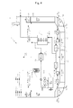
Fig. 1 is a block diagram illustrating a ballast water treatment apparatus for a ship using a forward osmosis process according to a first embodiment of the present invention; -
Fig. 2 is a block diagram illustrating a ballast water treatment apparatus for a ship using a forward osmosis process according to a second embodiment of the present invention; -
Fig. 3 is a block diagram illustrating a ballast water treatment apparatus for a ship using a forward osmosis process according to a third embodiment of the present invention; -
Fig. 4 is a block diagram illustrating a ballast water treatment apparatus for a ship using a forward osmosis process according to a fourth embodiment of the present invention; and -
Fig. 5 is a block diagram illustrating a ballast water treatment apparatus for a ship using a forward osmosis process according to a fifth embodiment of the present invention. - A ballast water treatment apparatus and method for a ship using a forward osmosis process according to exemplary embodiments of the present invention will be described below in more detail with reference to the accompanying drawings (herein, since a detailed configuration and function of the forward osmosis process are apparent to those skilled in the art, detailed description thereof will be omitted). The present invention may, however, be embodied in different forms and should not be construed as limited to the embodiments set forth herein. Rather, these embodiments are provided so that this disclosure will be thorough and complete, and will fully convey the scope of the present invention to those skilled in the art. Throughout the disclosure, like reference numerals refer to like parts throughout the various figures and embodiments of the present invention. The drawings are not necessarily to scale and in some instances, proportions may have been exaggerated in order to clearly illustrate features of the embodiments.
-
Fig. 1 is a block diagram illustrating a ballast water treatment apparatus for a ship using a forward osmosis process according to a first embodiment of the present invention. - As shown in
Fig. 1 , a ballastwater treatment apparatus 10 for a ship using a forward osmosis process according to a first embodiment of the present invention includes asea water pump 100 and awater collection part 200 for collecting sea water, afilter part 300 for filtering the collected sea water once, a forward osmosis process unit 400 for producing fresh water and ballast water by treating the filtered sea water, and atreatment water tank 500 and aballast water tank 600 for respectively storing the produced fresh water and ballast water. Here, the ballastwater treatment apparatus 10 may further include a carbon dioxide absorber 490 for treating carbon dioxide generated in aship 1. - The
sea water pump 100, thewater collection part 200, and thefilter part 300 are provided in theship 1 for collection of existing ballast water. Since a method of collecting sea water by thesea water pump 100 is a typical method which involves power consumption but is widely used, the method may be immediately applied to theship 1 to help in reducing cost. In addition, various methods, for example, a method of providing a dilute solution obtained by directly submerging a filtering membrane into sea water as ballast water, and a method of variably moving a diaphragm according to an amount of product water and dilute solution obtained by a membrane in one ballast water tank so as to adjust the amount of the dilute solution may be applied to theship 1. - The forward osmosis process unit 400 includes a pre-treatment part 410 which pre-treats the filtered sea water, a forward
osmosis membrane module 430 which infiltrates fresh water into a draw solution from sea water through contact between the pre-treated sea water and the draw solution by a membrane interposed therebetween so as to produce a mixture solution, arecovery module 450 which recovers the draw solution and separates the fresh water from the mixture solution of the draw solution and the fresh water, and a draw solution tank 470 which stores the draw solution used in the forwardosmosis membrane module 430. The fresh water is separated from the sea water through membrane exchange with the draw solution to be introduced into the draw solution in the forward osmosis process unit 400, and the fresh water (treatment water) introduced into the draw solution is separated from the draw solution to be utilized as living water, drinking water, or the like required within theship 1. In addition, a portion of the treatment water may be supplied to theballast water tank 600 to be used as ballast water in theship 1, and the draw solution used for separation of the fresh water may be reutilized or supplied to theballast water tank 600 to be used as ballast water in theship 1. - The forward osmosis process generally does not require a pre-treatment process, but the pre-treatment part 410 may be selectively provided to more effectively treat sea water collected to the
ship 1 and supply the treated sea water to the forward osmosis process unit 400. - The forward
osmosis membrane module 430 separates fresh water from sea water using a draw solution. A portion of the draw solution used in the forwardosmosis membrane module 430 is supplied as ballast water, and the remainder is introduced into therecovery module 450 so that fresh water is separated from the introduced draw solution. Various materials belonging to a volatile material group, an inorganic material group, an organic material group, and a synthesis material group may be used as the draw solution. The volatile material group may consist of ammonium bicarbonate, ammonium carbonate, etc., and the inorganic material group may consist of calcium nitrate, potassium chloride, sodium sulfate, etc. The organic material group may consist of magnesium acetate, sodium propionate, etc., and the synthesis material group may consist of sodium hexa phosphazene, etc. - The draw solution should be selected by preferentially considering safety of the
ship 1 and influence on a marine ecosystem and fully reviewing inflammability and harmfulness. The draw solution having a high concentration serves to prevent proliferation of microorganisms in the fresh water absorbed into the draw solution. In addition, when a material having a higher molecular weight than water is selected and used as ballast water, the same effect may be exhibited by a smaller amount compared to a case in which sea water is used as ballast water. Consequently, it may be possible to reduce capital expenditures and operating expenditures of theship 1. - A thermal method, a phase separation method, a membrane utilization method, a magnetic utilization method, a crystallization method, etc. may be used as a method of extracting fresh water from a draw solution and recovering the draw solution in the
recovery module 450. The thermal method is a method of recovering a draw solution having high volatility and a low boiling point using a difference between boiling points at intermediate and low temperatures. In the thermal method, waste heat of a stack 7 or heat exchanger of theship 1 may be used, and carbon dioxide required when the draw solution is recovered may be supplied from the stack 7 of theship 1. The phase separation method is a method of using a principle in which a draw solution is phase-separated when absorbing carbon dioxide at a certain temperature for each characteristic of the draw solution. The phase separation method may be easily applied since waste heat or carbon dioxide is supplied from the stack 7 or heat exchanger of theship 1. The membrane utilization method is a method of recovering a draw solution using a membrane such as an NF (Nano Filtration) membrane or an RO (Reverse Osmosis) membrane and may use surplus power of theship 1. In addition, when a solution capable of reacting to a magnetic field is used together with formation of an osmotic pressure, a draw solution may be separated using the magnetic utilization method. In a draw solution which is well dissolved in water at room and high temperatures to have an osmotic pressure and in which precipitation is generated due to low solubility at a low temperature, the crystallization method of separating the draw solution using waste heat of theship 1 and using sea water as ballast water may also be applied thereto. The first embodiment of the present invention recovers the draw solution using the thermal method from among the above-mentioned various methods. - As described above, the thermal method is a method of recovering a draw solution using a difference between boiling points, and may be used for a draw solution which is decomposed by heat to be easily recovered using distillation. In more detail, the thermal method may include a column distillation method under a condition of a low pressure and an intermediate/low temperature equal to or greater than 40°C, a vacuum distillation method under a condition of an intermediate temperature between 60°C and 90°C, a membrane distillation method under a condition of an intermediate temperature between 60°C and 80°C, etc.
- The draw solution absorbing water may have, for example, a form of ammonium bicarbonate (NH4HCO3). The ammonium bicarbonate is separated into ammonia, carbon dioxide, and water (NH3 + CO2 + H2O) by the
recovery module 450, and only the water in such a separated state to be supplied to thetreatment water tank 500. Subsequently, the draw solution is recovered by replenishing carbon dioxide through thecarbon dioxide absorber 490 to be described later. - The membrane used in the forward
osmosis membrane module 430 may be a tubular type membrane (having a form of integrating a plurality of separation membranes having a pipe shape in a pressure vessel) or a spiral wound type membrane (having a form of winding a flat membrane and a spacer layer around a tube for collecting permeated water), which is immediately applicable to the current ballast water treatment system. In addition, a hollow fiber type membrane capable of reducing a supply time of ballast water through mass production of treatment water may also be used as the membrane. - Although various application examples of the forward osmosis process unit 400 have been described above, the present invention is not limited thereto.
- Meanwhile, the
ship 1 includes an economizer 5, and the economizer 5 serves to recover waste heat from combustion gas discharged to the stack 7 from an engine 3 of theship 1 after combustion of fuel. The recovered waste heat is used for interior heating in theship 1, heating of living water, or the like, and therecovery module 450 recovers waste heat through the economizer 5 and uses the waste heat to collect the draw solution and separate fresh water therefrom. - The
carbon dioxide absorber 490 is additionally provided in a case of using a type of draw solution capable of being collected through absorption of carbon dioxide, and is used to separate fresh water from the draw solution. Since the draw solution separated into ammonia and carbon dioxide may not be recovered when water is separated and then the carbon dioxide is not fully supplied to the draw solution, thecarbon dioxide absorber 490 supplies the carbon dioxide from combustion gas to the draw solution so as to recover the draw solution. The draw solution requiring supply of carbon dioxide may representatively include ammonium bicarbonate, ammonium carbonate, etc. as volatile materials. - When the ballast water of the ship is produced using the forward osmosis process as described above, the waste heat and carbon dioxide of the ship may be utilized to thereby reduce energy. In addition, it may be possible to supply the ballast water of the ship and the fresh water required within the ship together.
- Hereinafter, a ballast water treatment apparatus for a ship using a forward osmosis process according to other embodiments of the present invention will be described. Here, detailed description of configurations and contents overlapped with those of the first embodiment will be omitted.
-
Fig. 2 is a block diagram illustrating a ballast water treatment apparatus for a ship using a forward osmosis process according to a second embodiment of the present invention. - As shown in
Fig. 2 , a ballastwater treatment apparatus 10 for aship 1 using a forward osmosis process according to a second embodiment of the present invention includes a forward osmosis process unit 400a which includes apre-treatment part 410a for pre-treating sea water, a forward osmosis membrane module 430a for infiltrating fresh water into a draw solution from sea water, arecovery module 450a for recovering the draw solution and separates the fresh water from a mixture solution of the draw solution and the fresh water, and a draw solution tank 470a for storing the draw solution used in the forward osmosis membrane module 430a. - The
recovery module 450a separates the draw solution using a phase separation method. The phase separation method uses a principle in which a draw solution is recovered through oil-water separation since, when an organic solvent having a strong polarity is used as the draw solution, the organic solvent is hydrophilic when carbon dioxide is absorbed by an SPS (Switchable Polarity Solvent) using ionization strength and the organic solvent is hydrophobic under a heating condition of absorbing nitrogen or air. The phase separation method uses a principle in which, when an FA-PEG draw solution is used as the draw solution, the draw solution is separated using a cloud point and separation capability thereof varies according to a concentration (10 ~ 90%) in a temperature range between 10°C and 70°C. The phase separation method uses a principle in which, when a polyoxy random copolymer is used as the draw solution, the draw solution is phase-separated in a temperature range between 75°C and 95°C according to a temperature of an oil-water separation device since the draw solution is phase-separated by heat. The carbon dioxide used for phase separation of the draw solution is supplied from combustion gas by acarbon dioxide separator 456a. - The
recovery module 450a operated by the above principle includes a liquid phase separator 454a which separates the draw solution from the mixture solution, acarbon dioxide separator 456a which is supplied with carbon dioxide through an economizer 5 to supply the carbon dioxide to the liquid phase separator 454a, and a separation membrane 452a which separates treatment water from the liquid phase separator 454a. The separation membrane 452a separates the draw solution by surplus power supplied from theship 1, and the fresh water separated from the draw solution is supplied to atreatment water tank 500 to be used as drinking water and living water in theship 1. A portion of the draw solution used in the forward osmosis membrane module 430a is supplied as ballast water. - The draw solution used here is representatively an SPS (Switchable Polarity Solvent) and may include tetrahydrofuran, MDEA, etc. A carbon dioxide contactor 490a is provided in order to treat the draw solution.
-
Fig. 3 is a block diagram illustrating a ballast water treatment apparatus for a ship using a forward osmosis process according to a third embodiment of the present invention. - As shown in
Fig. 3 , a ballastwater treatment apparatus 10 for aship 1 using a forward osmosis process according to a third embodiment of the present invention includes a forward osmosis process unit 400b which includes apre-treatment part 410b for pre-treating sea water, a forwardosmosis membrane module 430b for infiltrating fresh water into a draw solution from sea water, arecovery membrane 452b for recovering the draw solution and separating the fresh water from a mixture solution of the draw solution and the fresh water, and adraw solution tank 470b for storing the draw solution used in the forwardosmosis membrane module 430b. - The
recovery membrane 452b may be configured of an NF membrane or an RO membrane, and separates a draw solution from the mixture solution of the fresh water and the draw solution used in the forward osmosis process unit 400b by surplus power supplied from theship 1. The separated draw solution is recovered to thedraw solution tank 470b, and the separated fresh water is supplied to atreatment water tank 500 to be used as drinking water and living water in theship 1. The draw solution recovered through therecovery membrane 452b may include sodium chloride, sodium sulfate, magnesium sulfate, etc. as inorganic materials. - Since such a membrane utilization method requires power for membrane filtration at high pressure when the NF membrane or the RO membrane is used, the draw solution may be recovered by means of using the surplus power of the
ship 1. -
Fig. 4 is a block diagram illustrating a ballast water treatment apparatus for a ship using a forward osmosis process according to a fourth embodiment of the present invention. - As shown in
Fig. 4 , a ballastwater treatment apparatus 10 for aship 1 using a forward osmosis process according to a fourth embodiment of the present invention includes a forward osmosis process unit 400c which includes a pre-treatment part 410c for pre-treating sea water, a forwardosmosis membrane module 430c for infiltrating fresh water into a draw solution from sea water, amagnetic separator 452c for recovering the draw solution and separates the fresh water from a mixture solution of the draw solution and the fresh water, and a draw solution tank 470c for storing the draw solution used in the forwardosmosis membrane module 430c. - The
magnetic separator 452c may separate a draw solution reacting to a magnetic field by surplus power supplied from theship 1. The draw solution used to this end representatively include aluminum sulfate, PAA, PEG/with MNP, etc. - Such a magnetic utilization method uses a solution, which may form an osmotic pressure and react to the magnetic field, as the draw solution. Accordingly, the draw solution is separated using characteristics simultaneously having the osmotic pressure and magnetism by coating the draw solution with Tris (acetylacetonato) iron (III).
-
Fig. 5 is a block diagram illustrating a ballast water treatment apparatus for a ship using a forward osmosis process according to a fifth embodiment of the present invention. - As shown in
Fig. 5 , a ballastwater treatment apparatus 10 for aship 1 using a forward osmosis process according to a fifth embodiment of the present invention includes a forward osmosis process unit 400d which includes apre-treatment part 410d for pre-treating sea water, a forwardosmosis membrane module 430d for infiltrating fresh water into a draw solution from sea water, arecovery module 450d for recovering the draw solution and separating the fresh water from a mixture solution of the draw solution and the fresh water, and adraw solution tank 470d for storing the draw solution used in the forwardosmosis membrane module 430d. - The
recovery module 450d uses a crystallization method of separating a draw solution by cooling and crystallizing the draw solution. In the crystallization method, a draw solution having high solubility at a high temperature or a draw solution having low solubility at a low temperature may be selected if necessary. When the draw solution having high solubility at a high temperature is used in the crystallization method, a recovery amount of the draw solution and productivity of treatment water may be increased, an area of the forward osmosis membrane may be reduced, and capital cost and energy may be reduced. When the draw solution having low solubility at a low temperature is used in the crystallization method, the pressure of a pump and energy consumption may be reduced and capital cost and an area of the reverse osmosis membrane may be reduced. The waste heat of the ship may be utilized when the draw solution having high solubility at a high temperature is used, and the sea water may be utilized as coolant when the draw solution having low solubility at a low temperature is used. - The
recovery module 450d which separates the draw solution using the crystallization method includes a cooler 458d for cooling the draw solution, aprecipitation tank 454d for precipitating the draw solution and then recovering the draw solution to thedraw solution tank 470d, and aseparation membrane 452d which separates fresh water except for the precipitated draw solution. The cooler 458d and theseparation membrane 452d are operated by surplus power supplied from theship 1, and the fresh water separated by theseparation membrane 452d is supplied to thetreatment water tank 500. - The crystallized draw solution recovered to the
draw solution tank 470d is dissolved again by a heat exchanger 459d for heating the draw solution using heat recovered from the economizer 5 before being supplied to the forwardosmosis membrane module 430d, and is then supplied to the forwardosmosis membrane module 430d. More than one heat exchanger 459d may be provided. A first heat exchanger 459d may be used to heat the draw solution, and a second heat exchanger 459" may be used to heat the pre-treated sea water supplied to the forwardosmosis membrane module 430d. When the sea water is heated and used, the temperature of water is increased and the viscosity thereof is decreased, resulting in improvement of membrane permeability. Consequently, production efficiency of the treatment water may be improved. Remaining heat after being used in the first and second heat exchangers 459d and 459" is recovered again to the economizer 5 and then may be discharged to the outside of theship 1 through the stack 7 of theship 1 or be reused. - As is apparent from the above description, since sea water is treated using a forward osmosis process in a ballast water treatment apparatus and method for a ship using a forward osmosis process according to exemplary embodiments of the present invention, fresh water required within a ship can be supplied and the treated sea water can be used as ballast water. In addition, since waste heat and carbon dioxide generated in the ship are used to treat sea water, the ballast water can be treated and produced in a low-cost and high efficient manner.
- In addition, since salt water having a higher molecular weight than sea water generated by the forward osmosis process is used as the ballast water, the same effect can be exhibited by a smaller amount than the sea water. Since the treatment water generated by the forward osmosis process is eco-friendly treatment water without chemical components or harmful components, the treatment water can meet more stringent environmental regulations.
- While the present invention has been described with respect to the specific embodiments, it will be apparent to those skilled in the art that various changes and modifications may be made without departing from the spirit and scope of the invention as defined in the following claims.
Claims (15)
- A ballast water treatment apparatus for a ship, comprising:a water collection part for collecting sea water;a forward osmosis process unit for producing ballast water and treatment water obtained by desalinating the sea water collected through the water collection part, the forward osmosis process unit comprising a pre-treatment part for pre-treating the collected sea water; anda ballast water tank for storing the ballast water produced by the forward osmosis process unit.
- The ballast water treatment apparatus according to claim 1, wherein the forward osmosis process unit further comprises a forward osmosis membrane module which produces a mixture solution by infiltrating fresh water into a draw solution from the pre-treated sea water and supplies a portion of the produced mixture solution to the ballast water tank, a recovery module which recovers the draw solution and separates the desalinated treatment water from the mixture solution, a draw solution tank which stores the draw solution, and a treatment water tank which stores the treatment water.
- The ballast water treatment apparatus according to claim 2, wherein the recovery module recovers the draw solution using heat supplied from an economizer for absorbing waste heat of combustion gas discharged from an engine of a ship after combustion so as to supply the draw solution to the draw solution tank, the separated treatment water is supplied to the treatment water tank, and the recovery module further comprises a carbon dioxide absorber which absorbs carbon dioxide of the combustion gas into the recovered draw solution so that the draw solution absorbing the carbon dioxide is recovered to the draw solution tank.
- The ballast water treatment apparatus according to claim 2, wherein the recovery module comprises a carbon dioxide separator which separates carbon dioxide by absorbing waste heat of combustion gas discharged from an engine of a ship after combustion, a liquid phase separator which separates the draw solution using the separated carbon dioxide, a separation membrane which separates the treatment water from the liquid phase separator, and a carbon dioxide contactor which allows the draw solution separated from the liquid phase separator to come into contact with carbon dioxide of the combustion gas so that the draw solution coming into contact with the carbon dioxide is supplied to the draw solution tank.
- The ballast water treatment apparatus according to claim 2, wherein the recovery module comprises a recovery membrane which separates the draw solution and the treatment water from the mixture solution using surplus power supplied from a ship.
- The ballast water treatment apparatus according to claim 2, wherein the recovery module comprises a magnetic separator which separates the draw solution and the treatment water from the mixture solution using surplus power supplied from a ship.
- The ballast water treatment apparatus according to claim 2, wherein the recovery module comprises a cooler operated by surplus power supplied from a ship, a precipitation tank for precipitating the draw solution by lowering a temperature of the draw solution through the cooler and supplying the crystallized draw solution to the draw solution tank, and a separation membrane which separates the treatment water from the precipitation tank by the supplied surplus power.
- The ballast water treatment apparatus according to claim 7, wherein the recovery module further comprises a first heat exchanger which heats and dissolves the crystallized draw solution supplied to the draw solution tank using heat supplied from an economizer for absorbing waste heat of combustion gas discharged from an engine of the ship after combustion.
- The ballast water treatment apparatus according to claim 8, wherein the recovery module further comprises a second heat exchanger which heats the pre-treated sea water supplied to the forward osmosis membrane module using the heat supplied from the economizer.
- The ballast water treatment apparatus according to any one of the preceding claims, further comprising a filter part for filtering the sea water collected through the water collection part, and a sea water pump for pumping the sea water such that the sea water is collected through the water collection part and supplying the sea water filtered by the filter part to the pre-treatment part.
- The ballast water treatment apparatus according to any one of claims 2 to 10, wherein the draw solution is a material belonging to one of a volatile material group, an inorganic material group, an organic material group, and a synthesis material group.
- A ballast water treatment method for a ship, comprising:introducing sea water collected through a water collection part by a sea water pump into a forward osmosis membrane module of a forward osmosis process unit;producing a mixture solution by mixing a draw solution with fresh water of the sea water; andseparating desalinated treatment water from the mixture solution by a recovery module to supply the separated treatment water to a treatment water tank.
- The ballast water treatment method according to claim 12, further comprising performing a pre-treatment process before the sea water is introduced into the forward osmosis membrane module.
- The ballast water treatment method according to claim 12 or 13, further comprising separating the draw solution from the mixture solution by the recovery module to supply the separated draw solution to a draw solution tank.
- The ballast water treatment method according to any one of claims 12 to 15, wherein waste heat of a ship or carbon dioxide of combustion gas discharged from an engine of the ship after combustion is used to separate the draw solution by the recovery module.
Applications Claiming Priority (1)
| Application Number | Priority Date | Filing Date | Title |
|---|---|---|---|
| KR1020140104976A KR101636138B1 (en) | 2014-08-13 | 2014-08-13 | Ballast water treatment device and method for a ship using FO process |
Publications (2)
| Publication Number | Publication Date |
|---|---|
| EP3018104A1 true EP3018104A1 (en) | 2016-05-11 |
| EP3018104B1 EP3018104B1 (en) | 2018-09-12 |
Family
ID=53836388
Family Applications (1)
| Application Number | Title | Priority Date | Filing Date |
|---|---|---|---|
| EP15178173.9A Active EP3018104B1 (en) | 2014-08-13 | 2015-07-24 | Ballast water treatment apparatus and method for ship using forward osmosis process |
Country Status (3)
| Country | Link |
|---|---|
| US (1) | US10040533B2 (en) |
| EP (1) | EP3018104B1 (en) |
| KR (1) | KR101636138B1 (en) |
Cited By (1)
| Publication number | Priority date | Publication date | Assignee | Title |
|---|---|---|---|---|
| WO2025149419A1 (en) * | 2024-01-08 | 2025-07-17 | Maersk A/S | Method and system for removing carbon dioxide |
Families Citing this family (13)
| Publication number | Priority date | Publication date | Assignee | Title |
|---|---|---|---|---|
| US9962656B2 (en) * | 2016-09-21 | 2018-05-08 | Nrgtek, Inc. | Method of using new solvents for forward osmosis |
| US10143970B2 (en) | 2016-08-09 | 2018-12-04 | Nrgtek, Inc. | Power generation from low-temperature heat by hydro-osmotic processes |
| US9956522B2 (en) | 2016-08-09 | 2018-05-01 | Nrgtek, Inc. | Moisture removal from wet gases |
| US20180050933A1 (en) * | 2016-08-16 | 2018-02-22 | Naveed Aslam | Methods for reclaiming produced water |
| JP7178987B2 (en) * | 2016-08-22 | 2022-11-28 | トレヴィ システムズ インコーポレイテッド | Purification of osmotic fluids and their driving compounds |
| US11033855B2 (en) | 2016-09-02 | 2021-06-15 | Commonwealth Scientific And Industrial Research Organisation | Combined acidic gas capture and water extraction process |
| JP2018065539A (en) * | 2016-10-21 | 2018-04-26 | 三浦工業株式会社 | Ballast water treatment apparatus |
| US20180126336A1 (en) | 2016-11-04 | 2018-05-10 | Nrgtek, Inc. | Renewable Energy Storage Methods and Systems |
| KR102239302B1 (en) * | 2017-01-09 | 2021-04-09 | 한국조선해양 주식회사 | Floating marine structure with electric power generator |
| CN109592745A (en) * | 2018-10-30 | 2019-04-09 | 肇庆谛艾恩新材料科技发展有限公司 | A kind of efficient infiltration evaporation seawater desalination system using engine exhaust heat |
| EP3892098A1 (en) | 2020-04-11 | 2021-10-13 | DMK Deutsches Milchkontor GmbH | Process for the production of powders obtained from thermo-sensible sources |
| US12600689B2 (en) | 2021-01-15 | 2026-04-14 | Asahi Kasei Kabushiki Kaisha | Organic material liquid dehydration method |
| JP7815741B2 (en) * | 2021-12-21 | 2026-02-18 | 東洋紡エムシー株式会社 | Water treatment method and water treatment system |
Citations (8)
| Publication number | Priority date | Publication date | Assignee | Title |
|---|---|---|---|---|
| JP2005329300A (en) * | 2004-05-19 | 2005-12-02 | Japan Organo Co Ltd | Method and apparatus for preparing ballast water for ship |
| WO2010088170A2 (en) * | 2009-01-29 | 2010-08-05 | The Board Of Trustees Of The University Of Illinois | Solvent removal and recovery from inorganic and organic solutions |
| KR101204879B1 (en) | 2011-05-30 | 2012-11-26 | 한국원자력연구원 | Appratus for sterilization of ballast water, and the method of sterilization of ballast water using the same |
| WO2013004240A1 (en) * | 2011-07-06 | 2013-01-10 | Grundfos Holding A/S | A method for producing and storing desalinated water on a marine vessel |
| CN202849126U (en) * | 2012-09-18 | 2013-04-03 | 宁波莲华环保科技股份有限公司 | Seawater desalination system utilizing diesel engine on island or ship |
| KR101352521B1 (en) * | 2012-12-31 | 2014-01-17 | 두산중공업 주식회사 | Forward osmosis type complex system producing fresh water |
| US20140151295A1 (en) * | 2012-11-30 | 2014-06-05 | Korea Institute Of Science And Technology | Plants for advanced treatment of wastewater and method for treating wastewater using thereof |
| WO2014089142A1 (en) * | 2012-12-04 | 2014-06-12 | Robert Mcginnis | Signal responsive solutes |
Family Cites Families (6)
| Publication number | Priority date | Publication date | Assignee | Title |
|---|---|---|---|---|
| JP2010531732A (en) * | 2007-06-28 | 2010-09-30 | カレラ コーポレイション | Desalination method including precipitation of carbonate compounds |
| WO2009121366A2 (en) * | 2008-04-03 | 2009-10-08 | Povl Kaas | Filter unit with filter bank |
| KR101200838B1 (en) * | 2010-07-14 | 2012-11-13 | 한국기계연구원 | Apparatus and methods for electricity generation and water desalination |
| WO2012081747A1 (en) * | 2010-12-16 | 2012-06-21 | 광주과학기술원 | Forward-osmosis, continuous-process, water-treatment system and method using phase changes in an osmotically active substance |
| KR101220261B1 (en) * | 2011-07-27 | 2013-02-07 | 서울대학교산학협력단 | Thermal responsive draw agent for forward osmosis desalination and the forward osmosis desalination method using the draw agent |
| JP2014008469A (en) * | 2012-06-29 | 2014-01-20 | Hitachi Ltd | Water treatment system |
-
2014
- 2014-08-13 KR KR1020140104976A patent/KR101636138B1/en active Active
-
2015
- 2015-06-16 US US14/740,401 patent/US10040533B2/en active Active
- 2015-07-24 EP EP15178173.9A patent/EP3018104B1/en active Active
Patent Citations (9)
| Publication number | Priority date | Publication date | Assignee | Title |
|---|---|---|---|---|
| JP2005329300A (en) * | 2004-05-19 | 2005-12-02 | Japan Organo Co Ltd | Method and apparatus for preparing ballast water for ship |
| WO2010088170A2 (en) * | 2009-01-29 | 2010-08-05 | The Board Of Trustees Of The University Of Illinois | Solvent removal and recovery from inorganic and organic solutions |
| KR101204879B1 (en) | 2011-05-30 | 2012-11-26 | 한국원자력연구원 | Appratus for sterilization of ballast water, and the method of sterilization of ballast water using the same |
| WO2013004240A1 (en) * | 2011-07-06 | 2013-01-10 | Grundfos Holding A/S | A method for producing and storing desalinated water on a marine vessel |
| CN202849126U (en) * | 2012-09-18 | 2013-04-03 | 宁波莲华环保科技股份有限公司 | Seawater desalination system utilizing diesel engine on island or ship |
| US20140151295A1 (en) * | 2012-11-30 | 2014-06-05 | Korea Institute Of Science And Technology | Plants for advanced treatment of wastewater and method for treating wastewater using thereof |
| WO2014089142A1 (en) * | 2012-12-04 | 2014-06-12 | Robert Mcginnis | Signal responsive solutes |
| KR101352521B1 (en) * | 2012-12-31 | 2014-01-17 | 두산중공업 주식회사 | Forward osmosis type complex system producing fresh water |
| EP2939729A1 (en) * | 2012-12-31 | 2015-11-04 | Doosan Heavy Industries & Construction Co., Ltd. | Forward osmosis-type fresh water composite system |
Non-Patent Citations (1)
| Title |
|---|
| QINGCHUN GE ET AL: "Draw solutions for forward osmosis processes: Developments, challenges, and prospects for the future", JOURNAL OF MEMBRANE SCIENCE, vol. 442, 1 September 2013 (2013-09-01), pages 225 - 237, XP055149800, ISSN: 0376-7388, DOI: 10.1016/j.memsci.2013.03.046 * |
Cited By (1)
| Publication number | Priority date | Publication date | Assignee | Title |
|---|---|---|---|---|
| WO2025149419A1 (en) * | 2024-01-08 | 2025-07-17 | Maersk A/S | Method and system for removing carbon dioxide |
Also Published As
| Publication number | Publication date |
|---|---|
| KR101636138B1 (en) | 2016-07-05 |
| US10040533B2 (en) | 2018-08-07 |
| EP3018104B1 (en) | 2018-09-12 |
| US20160046360A1 (en) | 2016-02-18 |
| KR20160020602A (en) | 2016-02-24 |
Similar Documents
| Publication | Publication Date | Title |
|---|---|---|
| EP3018104B1 (en) | Ballast water treatment apparatus and method for ship using forward osmosis process | |
| US10315936B2 (en) | Forward osmosis separation processes | |
| US9044711B2 (en) | Osmotically driven membrane processes and systems and methods for draw solute recovery | |
| KR101577769B1 (en) | Forward osmosis separation processes | |
| AU2009326253B2 (en) | Process for operating a cooling tower comprising the treatment of feed water by direct osmosis | |
| JP2012120943A (en) | Alkali metal separation and recovery method, and alkali metal separation and recovery apparatus | |
| WO2016064689A2 (en) | Process for concentration of lithium containing solutions | |
| WO2012074074A1 (en) | Method and for separation and collection of purified alkali metal salt | |
| EP2618917A2 (en) | Osmotically driven membrane processes and systems and methods for draw solute recovery | |
| US9580337B2 (en) | Pressurized forward osmosis process and system | |
| WO2013005694A1 (en) | Method for separating and recovering alkali metal, and apparatus for separating and recovering alkali metal | |
| KR20150008236A (en) | Ballast water treatment | |
| AU2015255210B2 (en) | Osmotically driven membrane processes and systems and methods for draw solute recovery | |
| WO2025257582A1 (en) | Offshore lithium extraction |
Legal Events
| Date | Code | Title | Description |
|---|---|---|---|
| PUAI | Public reference made under article 153(3) epc to a published international application that has entered the european phase |
Free format text: ORIGINAL CODE: 0009012 |
|
| 17P | Request for examination filed |
Effective date: 20150724 |
|
| AK | Designated contracting states |
Kind code of ref document: A1 Designated state(s): AL AT BE BG CH CY CZ DE DK EE ES FI FR GB GR HR HU IE IS IT LI LT LU LV MC MK MT NL NO PL PT RO RS SE SI SK SM TR |
|
| AX | Request for extension of the european patent |
Extension state: BA ME |
|
| RBV | Designated contracting states (corrected) |
Designated state(s): AL AT BE BG CH CY CZ DE DK EE ES FI FR GB GR HR HU IE IS IT LI LT LU LV MC MK MT NL NO PL PT RO RS SE SI SK SM TR |
|
| STAA | Information on the status of an ep patent application or granted ep patent |
Free format text: STATUS: EXAMINATION IS IN PROGRESS |
|
| 17Q | First examination report despatched |
Effective date: 20170621 |
|
| GRAP | Despatch of communication of intention to grant a patent |
Free format text: ORIGINAL CODE: EPIDOSNIGR1 |
|
| STAA | Information on the status of an ep patent application or granted ep patent |
Free format text: STATUS: GRANT OF PATENT IS INTENDED |
|
| INTG | Intention to grant announced |
Effective date: 20180105 |
|
| GRAJ | Information related to disapproval of communication of intention to grant by the applicant or resumption of examination proceedings by the epo deleted |
Free format text: ORIGINAL CODE: EPIDOSDIGR1 |
|
| GRAL | Information related to payment of fee for publishing/printing deleted |
Free format text: ORIGINAL CODE: EPIDOSDIGR3 |
|
| GRAS | Grant fee paid |
Free format text: ORIGINAL CODE: EPIDOSNIGR3 |
|
| STAA | Information on the status of an ep patent application or granted ep patent |
Free format text: STATUS: EXAMINATION IS IN PROGRESS |
|
| INTC | Intention to grant announced (deleted) | ||
| GRAR | Information related to intention to grant a patent recorded |
Free format text: ORIGINAL CODE: EPIDOSNIGR71 |
|
| STAA | Information on the status of an ep patent application or granted ep patent |
Free format text: STATUS: GRANT OF PATENT IS INTENDED |
|
| INTG | Intention to grant announced |
Effective date: 20180629 |
|
| GRAA | (expected) grant |
Free format text: ORIGINAL CODE: 0009210 |
|
| STAA | Information on the status of an ep patent application or granted ep patent |
Free format text: STATUS: THE PATENT HAS BEEN GRANTED |
|
| AK | Designated contracting states |
Kind code of ref document: B1 Designated state(s): AL AT BE BG CH CY CZ DE DK EE ES FI FR GB GR HR HU IE IS IT LI LT LU LV MC MK MT NL NO PL PT RO RS SE SI SK SM TR |
|
| REG | Reference to a national code |
Ref country code: GB Ref legal event code: FG4D |
|
| REG | Reference to a national code |
Ref country code: CH Ref legal event code: EP |
|
| REG | Reference to a national code |
Ref country code: IE Ref legal event code: FG4D |
|
| REG | Reference to a national code |
Ref country code: DE Ref legal event code: R096 Ref document number: 602015015991 Country of ref document: DE |
|
| REG | Reference to a national code |
Ref country code: AT Ref legal event code: REF Ref document number: 1040350 Country of ref document: AT Kind code of ref document: T Effective date: 20181015 |
|
| REG | Reference to a national code |
Ref country code: NL Ref legal event code: MP Effective date: 20180912 |
|
| REG | Reference to a national code |
Ref country code: LT Ref legal event code: MG4D |
|
| PG25 | Lapsed in a contracting state [announced via postgrant information from national office to epo] |
Ref country code: LT Free format text: LAPSE BECAUSE OF FAILURE TO SUBMIT A TRANSLATION OF THE DESCRIPTION OR TO PAY THE FEE WITHIN THE PRESCRIBED TIME-LIMIT Effective date: 20180912 Ref country code: BG Free format text: LAPSE BECAUSE OF FAILURE TO SUBMIT A TRANSLATION OF THE DESCRIPTION OR TO PAY THE FEE WITHIN THE PRESCRIBED TIME-LIMIT Effective date: 20181212 Ref country code: SE Free format text: LAPSE BECAUSE OF FAILURE TO SUBMIT A TRANSLATION OF THE DESCRIPTION OR TO PAY THE FEE WITHIN THE PRESCRIBED TIME-LIMIT Effective date: 20180912 Ref country code: NO Free format text: LAPSE BECAUSE OF FAILURE TO SUBMIT A TRANSLATION OF THE DESCRIPTION OR TO PAY THE FEE WITHIN THE PRESCRIBED TIME-LIMIT Effective date: 20181212 Ref country code: GR Free format text: LAPSE BECAUSE OF FAILURE TO SUBMIT A TRANSLATION OF THE DESCRIPTION OR TO PAY THE FEE WITHIN THE PRESCRIBED TIME-LIMIT Effective date: 20181213 Ref country code: RS Free format text: LAPSE BECAUSE OF FAILURE TO SUBMIT A TRANSLATION OF THE DESCRIPTION OR TO PAY THE FEE WITHIN THE PRESCRIBED TIME-LIMIT Effective date: 20180912 Ref country code: FI Free format text: LAPSE BECAUSE OF FAILURE TO SUBMIT A TRANSLATION OF THE DESCRIPTION OR TO PAY THE FEE WITHIN THE PRESCRIBED TIME-LIMIT Effective date: 20180912 |
|
| PG25 | Lapsed in a contracting state [announced via postgrant information from national office to epo] |
Ref country code: LV Free format text: LAPSE BECAUSE OF FAILURE TO SUBMIT A TRANSLATION OF THE DESCRIPTION OR TO PAY THE FEE WITHIN THE PRESCRIBED TIME-LIMIT Effective date: 20180912 Ref country code: AL Free format text: LAPSE BECAUSE OF FAILURE TO SUBMIT A TRANSLATION OF THE DESCRIPTION OR TO PAY THE FEE WITHIN THE PRESCRIBED TIME-LIMIT Effective date: 20180912 Ref country code: HR Free format text: LAPSE BECAUSE OF FAILURE TO SUBMIT A TRANSLATION OF THE DESCRIPTION OR TO PAY THE FEE WITHIN THE PRESCRIBED TIME-LIMIT Effective date: 20180912 |
|
| REG | Reference to a national code |
Ref country code: AT Ref legal event code: MK05 Ref document number: 1040350 Country of ref document: AT Kind code of ref document: T Effective date: 20180912 |
|
| PG25 | Lapsed in a contracting state [announced via postgrant information from national office to epo] |
Ref country code: IS Free format text: LAPSE BECAUSE OF FAILURE TO SUBMIT A TRANSLATION OF THE DESCRIPTION OR TO PAY THE FEE WITHIN THE PRESCRIBED TIME-LIMIT Effective date: 20190112 Ref country code: AT Free format text: LAPSE BECAUSE OF FAILURE TO SUBMIT A TRANSLATION OF THE DESCRIPTION OR TO PAY THE FEE WITHIN THE PRESCRIBED TIME-LIMIT Effective date: 20180912 Ref country code: EE Free format text: LAPSE BECAUSE OF FAILURE TO SUBMIT A TRANSLATION OF THE DESCRIPTION OR TO PAY THE FEE WITHIN THE PRESCRIBED TIME-LIMIT Effective date: 20180912 Ref country code: RO Free format text: LAPSE BECAUSE OF FAILURE TO SUBMIT A TRANSLATION OF THE DESCRIPTION OR TO PAY THE FEE WITHIN THE PRESCRIBED TIME-LIMIT Effective date: 20180912 Ref country code: IT Free format text: LAPSE BECAUSE OF FAILURE TO SUBMIT A TRANSLATION OF THE DESCRIPTION OR TO PAY THE FEE WITHIN THE PRESCRIBED TIME-LIMIT Effective date: 20180912 Ref country code: CZ Free format text: LAPSE BECAUSE OF FAILURE TO SUBMIT A TRANSLATION OF THE DESCRIPTION OR TO PAY THE FEE WITHIN THE PRESCRIBED TIME-LIMIT Effective date: 20180912 Ref country code: NL Free format text: LAPSE BECAUSE OF FAILURE TO SUBMIT A TRANSLATION OF THE DESCRIPTION OR TO PAY THE FEE WITHIN THE PRESCRIBED TIME-LIMIT Effective date: 20180912 Ref country code: PL Free format text: LAPSE BECAUSE OF FAILURE TO SUBMIT A TRANSLATION OF THE DESCRIPTION OR TO PAY THE FEE WITHIN THE PRESCRIBED TIME-LIMIT Effective date: 20180912 Ref country code: ES Free format text: LAPSE BECAUSE OF FAILURE TO SUBMIT A TRANSLATION OF THE DESCRIPTION OR TO PAY THE FEE WITHIN THE PRESCRIBED TIME-LIMIT Effective date: 20180912 |
|
| PG25 | Lapsed in a contracting state [announced via postgrant information from national office to epo] |
Ref country code: SM Free format text: LAPSE BECAUSE OF FAILURE TO SUBMIT A TRANSLATION OF THE DESCRIPTION OR TO PAY THE FEE WITHIN THE PRESCRIBED TIME-LIMIT Effective date: 20180912 Ref country code: PT Free format text: LAPSE BECAUSE OF FAILURE TO SUBMIT A TRANSLATION OF THE DESCRIPTION OR TO PAY THE FEE WITHIN THE PRESCRIBED TIME-LIMIT Effective date: 20190112 Ref country code: SK Free format text: LAPSE BECAUSE OF FAILURE TO SUBMIT A TRANSLATION OF THE DESCRIPTION OR TO PAY THE FEE WITHIN THE PRESCRIBED TIME-LIMIT Effective date: 20180912 |
|
| REG | Reference to a national code |
Ref country code: DE Ref legal event code: R097 Ref document number: 602015015991 Country of ref document: DE |
|
| PLBE | No opposition filed within time limit |
Free format text: ORIGINAL CODE: 0009261 |
|
| STAA | Information on the status of an ep patent application or granted ep patent |
Free format text: STATUS: NO OPPOSITION FILED WITHIN TIME LIMIT |
|
| PG25 | Lapsed in a contracting state [announced via postgrant information from national office to epo] |
Ref country code: DK Free format text: LAPSE BECAUSE OF FAILURE TO SUBMIT A TRANSLATION OF THE DESCRIPTION OR TO PAY THE FEE WITHIN THE PRESCRIBED TIME-LIMIT Effective date: 20180912 |
|
| 26N | No opposition filed |
Effective date: 20190613 |
|
| PG25 | Lapsed in a contracting state [announced via postgrant information from national office to epo] |
Ref country code: SI Free format text: LAPSE BECAUSE OF FAILURE TO SUBMIT A TRANSLATION OF THE DESCRIPTION OR TO PAY THE FEE WITHIN THE PRESCRIBED TIME-LIMIT Effective date: 20180912 |
|
| REG | Reference to a national code |
Ref country code: DE Ref legal event code: R119 Ref document number: 602015015991 Country of ref document: DE |
|
| PG25 | Lapsed in a contracting state [announced via postgrant information from national office to epo] |
Ref country code: MC Free format text: LAPSE BECAUSE OF FAILURE TO SUBMIT A TRANSLATION OF THE DESCRIPTION OR TO PAY THE FEE WITHIN THE PRESCRIBED TIME-LIMIT Effective date: 20180912 |
|
| REG | Reference to a national code |
Ref country code: CH Ref legal event code: PL |
|
| PG25 | Lapsed in a contracting state [announced via postgrant information from national office to epo] |
Ref country code: TR Free format text: LAPSE BECAUSE OF FAILURE TO SUBMIT A TRANSLATION OF THE DESCRIPTION OR TO PAY THE FEE WITHIN THE PRESCRIBED TIME-LIMIT Effective date: 20180912 |
|
| REG | Reference to a national code |
Ref country code: BE Ref legal event code: MM Effective date: 20190731 |
|
| PG25 | Lapsed in a contracting state [announced via postgrant information from national office to epo] |
Ref country code: DE Free format text: LAPSE BECAUSE OF NON-PAYMENT OF DUE FEES Effective date: 20200201 |
|
| PG25 | Lapsed in a contracting state [announced via postgrant information from national office to epo] |
Ref country code: LI Free format text: LAPSE BECAUSE OF NON-PAYMENT OF DUE FEES Effective date: 20190731 Ref country code: LU Free format text: LAPSE BECAUSE OF NON-PAYMENT OF DUE FEES Effective date: 20190724 Ref country code: CH Free format text: LAPSE BECAUSE OF NON-PAYMENT OF DUE FEES Effective date: 20190731 Ref country code: BE Free format text: LAPSE BECAUSE OF NON-PAYMENT OF DUE FEES Effective date: 20190731 |
|
| PG25 | Lapsed in a contracting state [announced via postgrant information from national office to epo] |
Ref country code: IE Free format text: LAPSE BECAUSE OF NON-PAYMENT OF DUE FEES Effective date: 20190724 |
|
| PG25 | Lapsed in a contracting state [announced via postgrant information from national office to epo] |
Ref country code: CY Free format text: LAPSE BECAUSE OF FAILURE TO SUBMIT A TRANSLATION OF THE DESCRIPTION OR TO PAY THE FEE WITHIN THE PRESCRIBED TIME-LIMIT Effective date: 20180912 |
|
| PG25 | Lapsed in a contracting state [announced via postgrant information from national office to epo] |
Ref country code: HU Free format text: LAPSE BECAUSE OF FAILURE TO SUBMIT A TRANSLATION OF THE DESCRIPTION OR TO PAY THE FEE WITHIN THE PRESCRIBED TIME-LIMIT; INVALID AB INITIO Effective date: 20150724 Ref country code: MT Free format text: LAPSE BECAUSE OF FAILURE TO SUBMIT A TRANSLATION OF THE DESCRIPTION OR TO PAY THE FEE WITHIN THE PRESCRIBED TIME-LIMIT Effective date: 20180912 |
|
| PG25 | Lapsed in a contracting state [announced via postgrant information from national office to epo] |
Ref country code: MK Free format text: LAPSE BECAUSE OF FAILURE TO SUBMIT A TRANSLATION OF THE DESCRIPTION OR TO PAY THE FEE WITHIN THE PRESCRIBED TIME-LIMIT Effective date: 20180912 |
|
| PGFP | Annual fee paid to national office [announced via postgrant information from national office to epo] |
Ref country code: GB Payment date: 20250605 Year of fee payment: 11 |
|
| PGFP | Annual fee paid to national office [announced via postgrant information from national office to epo] |
Ref country code: FR Payment date: 20250610 Year of fee payment: 11 |