EP3018055A1 - Connecting rod for a flight control surface actuation system - Google Patents
Connecting rod for a flight control surface actuation system Download PDFInfo
- Publication number
- EP3018055A1 EP3018055A1 EP14306780.9A EP14306780A EP3018055A1 EP 3018055 A1 EP3018055 A1 EP 3018055A1 EP 14306780 A EP14306780 A EP 14306780A EP 3018055 A1 EP3018055 A1 EP 3018055A1
- Authority
- EP
- European Patent Office
- Prior art keywords
- connecting rod
- sensor
- flight control
- control surface
- position sensor
- Prior art date
- Legal status (The legal status is an assumption and is not a legal conclusion. Google has not performed a legal analysis and makes no representation as to the accuracy of the status listed.)
- Granted
Links
Images

Classifications
-
- B—PERFORMING OPERATIONS; TRANSPORTING
- B64—AIRCRAFT; AVIATION; COSMONAUTICS
- B64C—AEROPLANES; HELICOPTERS
- B64C13/00—Control systems or transmitting systems for actuating flying-control surfaces, lift-increasing flaps, air brakes, or spoilers
- B64C13/24—Transmitting means
- B64C13/26—Transmitting means without power amplification or where power amplification is irrelevant
- B64C13/28—Transmitting means without power amplification or where power amplification is irrelevant mechanical
-
- B—PERFORMING OPERATIONS; TRANSPORTING
- B64—AIRCRAFT; AVIATION; COSMONAUTICS
- B64C—AEROPLANES; HELICOPTERS
- B64C13/00—Control systems or transmitting systems for actuating flying-control surfaces, lift-increasing flaps, air brakes, or spoilers
- B64C13/24—Transmitting means
- B64C13/26—Transmitting means without power amplification or where power amplification is irrelevant
- B64C13/28—Transmitting means without power amplification or where power amplification is irrelevant mechanical
- B64C13/30—Transmitting means without power amplification or where power amplification is irrelevant mechanical using cable, chain, or rod mechanisms
-
- B—PERFORMING OPERATIONS; TRANSPORTING
- B64—AIRCRAFT; AVIATION; COSMONAUTICS
- B64C—AEROPLANES; HELICOPTERS
- B64C13/00—Control systems or transmitting systems for actuating flying-control surfaces, lift-increasing flaps, air brakes, or spoilers
- B64C13/24—Transmitting means
- B64C13/38—Transmitting means with power amplification
- B64C13/50—Transmitting means with power amplification using electrical energy
Definitions
- the present disclosure relates to a flight control surface actuation system and a connecting rod for use in such a system.
- rotary actuators to control the position of flight control surfaces on an aircraft.
- An example of a flight control surface is a spoiler, which is positioned on a trailing edge of an aircraft wing. The spoiler can be extended upwardly, from a stowed position flush to the wing to a raised position, to reduce the lift created by the wing.
- an elongate connecting rod In order to connect the rotary output shaft to the flight control surface, it is common to use an elongate connecting rod.
- the present disclosure seeks to provide an improved connecting rod and actuation system.
- connecting rod assembly for a flight control surface actuation system, the assembly comprising a connecting rod for connecting a flight control surface to a rotary actuator and a position sensor mounted to the connecting rod for sensing the position of the connecting rod relative to a rotary actuator.
- Providing a position sensor on the connecting rod may mean that a position sensor will not need to be provided in or on the rotary actuator. It may be easier to access and/or replace a position sensor on a connecting rod than one that is inside (or attached to) an actuator.
- connection should be understood to refer to any type of direct or indirect connection.
- connection may be via one or more intervening members that are connected to one or both of the two parts.
- the position sensor may be any type of sensor that is operable to determine the relative position, in use, between the connecting rod and a rotary actuator connected thereto.
- the term 'connecting rod' should be understood to refer to an elongated member that is configured to be operatively connected between a flight control surface and a rotary actuator, in such a way that the output motion of the actuator can be transmitted by the rod to extend (i.e. open) and/or retract (i.e. close) the flight control surface.
- 'operatively connected should be understood to refer to connection of two parts in such a way that one of the parts can operate the other and possibly vice versa.
- one part may drive the other in some way.
- two parts that are operatively connected may be indirectly connected to each other.
- the position sensor may be arranged to measure a rotation of the connecting rod relative to a rotary actuator.
- the sensor may be a rotation sensor.
- the position sensor may measure the rotation of a certain part, or the whole, of the rod.
- the connecting rod may comprise a first end and a second end.
- the first end may be configured to be operatively connected to a rotary actuator and the second end may be configured to be operatively connected to a flight control surface.
- the connecting rod may comprise first and second rod arms, which extend parallel to each other towards the first end.
- the position sensor may measure the rotation of the first end of the rod about the axis of rotation of the rotational actuator.
- a first part of the position sensor may be secured to the connecting rod in a fixed position (i.e. so that it moves with the rod, not relative thereto), which may be at or near the first end of the rod.
- a second part of the position sensor may be rotatably mounted to the first part and the position sensor may be configured to measure the relative rotation between the first and second parts.
- the second part may be configured for connection to a rotary output shaft of a rotary actuator.
- the position sensor may form part (or the whole) of the connection between the rod and the rotary output shaft.
- the position sensor may be mounted to at least one of the connecting rod arms.
- the position sensor may be any suitable type of sensor, such as a Hall-Effect sensor, a Rotary Variable Differential Transformer (RVDT) or a potentiometer.
- a Hall-Effect sensor such as a Hall-Effect sensor, a Rotary Variable Differential Transformer (RVDT) or a potentiometer.
- RVDT Rotary Variable Differential Transformer
- the assembly may also comprise a load sensor mounted to the connecting rod for measuring a force exerted along the connecting rod.
- the load sensor may be able to measure both compressive and tensile forces along the rod.
- the load sensor may be located adjacent the second end of the rod, but other locations may be suitable.
- the load sensor may be any suitable type of sensor, such as a load cell, a strain gauge, a piezoelectric sensor, a semiconductor load sensor or a magnetostrictive load sensor.
- the assembly may comprise an electronic module mounted to the connecting rod and configured to receive a first signal from the position and/or load sensor and transmit a second signal to a location remote from the connecting rod.
- the module may transmit the second signal wirelessly.
- the module may comprise wired connections between the load and/or position sensors, or alternatively, these connections may be wireless.
- the module may transmit the second signal, e.g. wirelessly, to a flight control computer (e.g. in an aircraft cockpit) and/or to an electronic control unit of a rotary actuator. This provides a dynamic feedback loop for the control of the actuator based on the position of the connecting rod (and therefore the flight control surface).
- a flight control computer e.g. in an aircraft cockpit
- an electronic control unit of a rotary actuator e.g. in an aircraft cockpit
- the module may be positioned between the first and second connecting rod arms.
- the present disclosure also extends to a flight control surface actuation system comprising a rotary actuator having an output shaft configured to rotate about an axis and a connecting rod assembly as described above.
- the connecting rod is operatively connected to the output shaft such that rotation of the output shaft about its axis causes at least part of the connection rod to rotate about the same axis.
- the part of the rod that rotates about the axis may be the first end.
- the position sensor may be arranged to measure the angular displacement of the first end of the connecting rod about the axis.
- the second part of the position sensor may be configured to rotate with the output shaft relative to the first end of the connecting rod.
- the second part of the position sensor may comprise a sensor shaft that is operatively connected to the actuator output shaft and that is rotatably mounted to the connecting rod. As such, the rod may rotate about the position sensor, and, in particular, about the sensor shaft. The position sensor measures the extent of this rotation.
- the actuator output shaft may be connected to an output lever and the output lever may be connected to the connecting rod.
- the second part of the position sensor e.g. the sensor shaft
- the rod is operatively connected to the output shaft via the position sensor (comprising the first and second parts) and the output lever.
- the present disclosure also extends to a method of controlling a flight control surface comprising using the system described above to vary the position of a flight control surface.
- the method may further comprise using the load and position sensor measurements to control the actuator.
- the present disclosure also extends to an aircraft comprising at least one flight control surface and the assembly or system as described above, wherein the connecting rod is connected to the flight control surface.
- the flight control surface may be a spoiler on an aircraft wing.
- FIG. 1 shows a flight control surface actuation system 10 according to an embodiment of the present disclosure.
- the system 10 comprises a rotary actuator 12 having a rotary output shaft 14 rotatable around an axis R.
- the shaft 14 is encircled by (and engaged with) an output lever 18.
- a connecting rod 16 is used to control the position of a flight control surface (not shown) connected thereto, as is known in the art.
- the flight control surface may be, for example, a spoiler on an aircraft wing.
- a first end 15 of the connecting rod 16 is rotatably connected to the output lever 18 and a second end 17 of the connecting rod 16 is configured to be connected to a flight control surface via an eye 17a.
- the output lever 18 is only a feature of this specific embodiment, and that in alternative embodiments, the connecting rod 16 could be connected to the output shaft 14 directly, or via a plurality of output levers.
- the connecting rod 16 has two arms 16a, 16b, which extend parallel to each other towards the first end 15 of the rod 16.
- a position sensor 20 is mounted to the connecting rod 16 and to the output lever 18 and forms a connection therebetween.
- the position sensor is located adjacent to the first end 15 of the rod 16.
- the position sensor 20 is mounted to rod arm 16a, but could be mounted to rod arm 16b.
- the position sensor 20 is arranged to measure the position of the connecting rod 16 relative to the output lever 18 and thus relative to the rotational axis R of the rotary actuator 12. Measuring the position of the rod 16 about the axis R (i.e. the angular displacement of the first end 15 of the rod 16 relative to the axis) enables the extension of a flight control surface (not shown) connected to the rod 16 to be determined.
- a load sensor 30 is mounted to the connecting rod 16 for measuring the load exerted on the connecting rod 16.
- the load sensor 30 is located between the eye 17a and the rod arms 16a, 16b, but it should be understood that the load sensor could be located at any suitable point along the rod 16.
- the load sensor 30 is configured to measure a force exerted along the rod 16 from the rotary actuator 12 towards the second end 17 and/or from a flight control surface towards the first end 15 via the eye 17a.
- the load sensor 30 can be any appropriate sensor known in the art that generates a signal indicative of the load exerted on the connecting rod 16.
- sensors may include a load cell, a strain gauge, a piezoelectric sensor, a semiconductor load sensor or a magnetostrictive load sensor.
- the position and load sensors 20, 30 each comprise a wire output port 21, 31 for receiving a wire (not shown) connected to an electronic module 40 located between the rod arms 16a, 16b.
- the electronic module 40 is configured to receive position and load signals from the sensors 20, 30 and transmit signals wirelessly or through wires (not shown) to a flight computer and/or to a control unit in the rotary actuator 12. This allows feedback from the sensors 20, 30 to be used in controlling the amount of actuation of a flight control surface.
- Mounting the electronic module 40 between the rod arms 16a and 16b is advantageous in that it acts to shields and protect it.
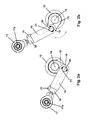
- Fig 2a shows the actuation system 10 in a retracted position and Fig 2b shows the rod 16 in an extended position.
- the rotary actuator 12 is activated to rotate output shaft 14 and output lever 18 around axis R.
- the first end 15 of the connecting rod 16 is rotatably connected to the output lever 18 and the connecting rod 16 is free to rotate around this connection point, such that as the first end 15 rotates around the axis R due to the rotation of the output lever 18 the connecting rod 16 pivots at the connection point.
- a flight control surface (not shown) is operatively connected to the second end 17 of the connecting rod 16, the rotation of the output shaft 14 and pivoting of the connecting rod 16 at the first end 15 allow movement of the connecting rod 16 upward ( Figs 2a and 2b ), causing the flight control surface to move from a first stowed position (where, for example, it is flush with an aircraft wing surface) to a second raised position, where, for example, it is extended upwardly from an aircraft wing surface.
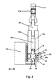
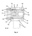
- Figs 3 and 4 show cross-sectional views through the system 10.
- Fig 3 shows a cross-section through the length of the connecting rod 16, output lever 18 and position sensor 20 along line A-A (see Fig 1 )
- Fig 4 shows the cross-section through the connecting rod 16, output lever 18 and position sensor 20 along line B-B (see Fig 1 ).
- Figs 3 and 4 show the two connecting rod arms 16a, 16b each connected to an engagement part 19 of the output lever 18.
- Bearings 13a, 13b are mounted between the part 19 and rod arms 16a, 16b to allow the rod 16 to freely rotate about the output lever 18 at first end 15.
- the position sensor 20 comprises a housing 23, mounted to rod arm 16a in a fixed manner, so that it moves with the rod arm 16a, not relative thereto, using fasteners 24a and 24b, and a sensor shaft 22, rotatably connected to the housing 23.
- a cap 26 is also secured to second rod arm 16b through fastener 26a.
- the sensor shaft 22 engages with the output lever 18 at engagement part 19, and rotates with the output lever 18.
- the housing 23 remains fixed to the connecting rod arm 16a, thus the sensor shaft 22 rotates relative to the housing 23.
- a signal indicative of the amount of rotation is generated by the position sensor 20, as is known in the art.
- This signal is used to indicate the position of the connecting rod 16 and, in turn, the flight control surface (not shown).
- the position sensor 20 is a contactless Hall-effect sensor.
- any suitable position sensor may be used, for example, a Rotary Variable Differential Transformer (RVDT) or a potentiometer.
- RVDT Rotary Variable Differential Transformer
- Mounting the load sensor 30 and position sensor 20 to the connecting rod 16 may remove the need for a sensor to be housed within or on the rotary actuator 12. This may reduce the size of the actuator 12 and make the sensors 20, 30 easier to access and replace. Furthermore, since the connecting rod 16 is loaded directly in tension/compression during use, integrating a load sensor 30 thereon allows easier and more accurate measurements thereof, without having to account for any actuator internal friction.
Landscapes
- Engineering & Computer Science (AREA)
- Mechanical Engineering (AREA)
- Automation & Control Theory (AREA)
- Aviation & Aerospace Engineering (AREA)
- Transmission Devices (AREA)
- Mechanical Control Devices (AREA)
Abstract
Description
- The present disclosure relates to a flight control surface actuation system and a connecting rod for use in such a system.
- It is known to use rotary actuators to control the position of flight control surfaces on an aircraft. An example of a flight control surface is a spoiler, which is positioned on a trailing edge of an aircraft wing. The spoiler can be extended upwardly, from a stowed position flush to the wing to a raised position, to reduce the lift created by the wing. In order to connect the rotary output shaft to the flight control surface, it is common to use an elongate connecting rod.
- In prior art rotary actuators, it is known to provide some sort of position sensor on the actuator output shaft to determine the angular displacement thereof, which in turn, allows the position of the flight control surface to be determined.
- The present disclosure seeks to provide an improved connecting rod and actuation system.
- There is disclosed herein a connecting rod assembly for a flight control surface actuation system, the assembly comprising a connecting rod for connecting a flight control surface to a rotary actuator and a position sensor mounted to the connecting rod for sensing the position of the connecting rod relative to a rotary actuator.
- Providing a position sensor on the connecting rod may mean that a position sensor will not need to be provided in or on the rotary actuator. It may be easier to access and/or replace a position sensor on a connecting rod than one that is inside (or attached to) an actuator.
- The term 'connecting' should be understood to refer to any type of direct or indirect connection. In an indirect connection between two parts, the connection may be via one or more intervening members that are connected to one or both of the two parts.
- The position sensor may be any type of sensor that is operable to determine the relative position, in use, between the connecting rod and a rotary actuator connected thereto.
- The term 'connecting rod' should be understood to refer to an elongated member that is configured to be operatively connected between a flight control surface and a rotary actuator, in such a way that the output motion of the actuator can be transmitted by the rod to extend (i.e. open) and/or retract (i.e. close) the flight control surface.
- The term 'operatively connected' should be understood to refer to connection of two parts in such a way that one of the parts can operate the other and possibly vice versa. For example, one part may drive the other in some way. As such, two parts that are operatively connected may be indirectly connected to each other.
- The position sensor may be arranged to measure a rotation of the connecting rod relative to a rotary actuator. As such, the sensor may be a rotation sensor. The position sensor may measure the rotation of a certain part, or the whole, of the rod.
- The connecting rod may comprise a first end and a second end. The first end may be configured to be operatively connected to a rotary actuator and the second end may be configured to be operatively connected to a flight control surface.
- The connecting rod may comprise first and second rod arms, which extend parallel to each other towards the first end.
- The position sensor may measure the rotation of the first end of the rod about the axis of rotation of the rotational actuator.
- A first part of the position sensor may be secured to the connecting rod in a fixed position (i.e. so that it moves with the rod, not relative thereto), which may be at or near the first end of the rod. A second part of the position sensor may be rotatably mounted to the first part and the position sensor may be configured to measure the relative rotation between the first and second parts.
- The second part may be configured for connection to a rotary output shaft of a rotary actuator. As such, the position sensor may form part (or the whole) of the connection between the rod and the rotary output shaft.
- The position sensor may be mounted to at least one of the connecting rod arms.
- The position sensor may be any suitable type of sensor, such as a Hall-Effect sensor, a Rotary Variable Differential Transformer (RVDT) or a potentiometer.
- The assembly may also comprise a load sensor mounted to the connecting rod for measuring a force exerted along the connecting rod. The load sensor may be able to measure both compressive and tensile forces along the rod.
- The load sensor may be located adjacent the second end of the rod, but other locations may be suitable.
- The load sensor may be any suitable type of sensor, such as a load cell, a strain gauge, a piezoelectric sensor, a semiconductor load sensor or a magnetostrictive load sensor.
- The assembly may comprise an electronic module mounted to the connecting rod and configured to receive a first signal from the position and/or load sensor and transmit a second signal to a location remote from the connecting rod. The module may transmit the second signal wirelessly. The module may comprise wired connections between the load and/or position sensors, or alternatively, these connections may be wireless.
- The module may transmit the second signal, e.g. wirelessly, to a flight control computer (e.g. in an aircraft cockpit) and/or to an electronic control unit of a rotary actuator. This provides a dynamic feedback loop for the control of the actuator based on the position of the connecting rod (and therefore the flight control surface).
- The module may be positioned between the first and second connecting rod arms.
- The present disclosure also extends to a flight control surface actuation system comprising a rotary actuator having an output shaft configured to rotate about an axis and a connecting rod assembly as described above. The connecting rod is operatively connected to the output shaft such that rotation of the output shaft about its axis causes at least part of the connection rod to rotate about the same axis.
- The part of the rod that rotates about the axis may be the first end.
- The position sensor may be arranged to measure the angular displacement of the first end of the connecting rod about the axis.
- The second part of the position sensor may be configured to rotate with the output shaft relative to the first end of the connecting rod.
- The second part of the position sensor may comprise a sensor shaft that is operatively connected to the actuator output shaft and that is rotatably mounted to the connecting rod. As such, the rod may rotate about the position sensor, and, in particular, about the sensor shaft. The position sensor measures the extent of this rotation.
- The actuator output shaft may be connected to an output lever and the output lever may be connected to the connecting rod. In such an arrangement, the second part of the position sensor, e.g. the sensor shaft, is mounted to the output lever, and the rod is operatively connected to the output shaft via the position sensor (comprising the first and second parts) and the output lever.
- The present disclosure also extends to a method of controlling a flight control surface comprising using the system described above to vary the position of a flight control surface.
- The method may further comprise using the load and position sensor measurements to control the actuator.
- The present disclosure also extends to an aircraft comprising at least one flight control surface and the assembly or system as described above, wherein the connecting rod is connected to the flight control surface.
- The flight control surface may be a spoiler on an aircraft wing.
- An exemplary embodiment of the present disclosure will now be described by way of example only and with reference to
Figures 1 to 4 , of which: -
Figure 1 is a perspective view of an exemplary flight control surface actuation system in accordance with an embodiment of the present disclosure; -
Figures 2a and 2b show side views of the actuation system ofFig. 1 in a retracted position and an extended position; -
Figure 3 shows a first cross-sectional view through the actuation systems ofFigs 1 and2 ; and -
Figure 4 shows a second cross-sectional view through the actuation systems ofFigs 1 to 3 . -
Figure 1 shows a flight controlsurface actuation system 10 according to an embodiment of the present disclosure. Thesystem 10 comprises arotary actuator 12 having arotary output shaft 14 rotatable around an axis R. Theshaft 14 is encircled by (and engaged with) anoutput lever 18. - A connecting
rod 16 is used to control the position of a flight control surface (not shown) connected thereto, as is known in the art. The flight control surface may be, for example, a spoiler on an aircraft wing. - A
first end 15 of the connectingrod 16 is rotatably connected to theoutput lever 18 and asecond end 17 of the connectingrod 16 is configured to be connected to a flight control surface via aneye 17a. - It should be understood that the
output lever 18 is only a feature of this specific embodiment, and that in alternative embodiments, the connectingrod 16 could be connected to theoutput shaft 14 directly, or via a plurality of output levers. - The connecting
rod 16 has twoarms first end 15 of therod 16. - A
position sensor 20 is mounted to the connectingrod 16 and to theoutput lever 18 and forms a connection therebetween. The position sensor is located adjacent to thefirst end 15 of therod 16. In this embodiment, theposition sensor 20 is mounted torod arm 16a, but could be mounted torod arm 16b. - The
position sensor 20 is arranged to measure the position of the connectingrod 16 relative to theoutput lever 18 and thus relative to the rotational axis R of therotary actuator 12. Measuring the position of therod 16 about the axis R (i.e. the angular displacement of thefirst end 15 of therod 16 relative to the axis) enables the extension of a flight control surface (not shown) connected to therod 16 to be determined. - A
load sensor 30 is mounted to the connectingrod 16 for measuring the load exerted on the connectingrod 16. In this embodiment, theload sensor 30 is located between theeye 17a and therod arms rod 16. - The
load sensor 30 is configured to measure a force exerted along therod 16 from therotary actuator 12 towards thesecond end 17 and/or from a flight control surface towards thefirst end 15 via theeye 17a. - The
load sensor 30 can be any appropriate sensor known in the art that generates a signal indicative of the load exerted on the connectingrod 16. Such sensors may include a load cell, a strain gauge, a piezoelectric sensor, a semiconductor load sensor or a magnetostrictive load sensor. - The position and
load sensors wire output port electronic module 40 located between therod arms electronic module 40 is configured to receive position and load signals from thesensors rotary actuator 12. This allows feedback from thesensors electronic module 40 between therod arms -
Fig 2a shows theactuation system 10 in a retracted position andFig 2b shows therod 16 in an extended position. - In operation, when flight control surface actuation is required, the
rotary actuator 12 is activated to rotateoutput shaft 14 andoutput lever 18 around axis R. As described in more detail below in relation toFigs 3 and4 , thefirst end 15 of the connectingrod 16 is rotatably connected to theoutput lever 18 and the connectingrod 16 is free to rotate around this connection point, such that as thefirst end 15 rotates around the axis R due to the rotation of theoutput lever 18 the connectingrod 16 pivots at the connection point. When a flight control surface (not shown) is operatively connected to thesecond end 17 of the connectingrod 16, the rotation of theoutput shaft 14 and pivoting of the connectingrod 16 at thefirst end 15 allow movement of the connectingrod 16 upward (Figs 2a and 2b ), causing the flight control surface to move from a first stowed position (where, for example, it is flush with an aircraft wing surface) to a second raised position, where, for example, it is extended upwardly from an aircraft wing surface. -
Figs 3 and4 show cross-sectional views through thesystem 10. In particular,Fig 3 shows a cross-section through the length of the connectingrod 16,output lever 18 andposition sensor 20 along line A-A (seeFig 1 ) andFig 4 shows the cross-section through the connectingrod 16,output lever 18 andposition sensor 20 along line B-B (seeFig 1 ). -
Figs 3 and4 show the two connectingrod arms engagement part 19 of theoutput lever 18.Bearings part 19 androd arms rod 16 to freely rotate about theoutput lever 18 atfirst end 15. Theposition sensor 20 comprises ahousing 23, mounted torod arm 16a in a fixed manner, so that it moves with therod arm 16a, not relative thereto, usingfasteners sensor shaft 22, rotatably connected to thehousing 23. Acap 26 is also secured tosecond rod arm 16b throughfastener 26a. Thesensor shaft 22 engages with theoutput lever 18 atengagement part 19, and rotates with theoutput lever 18. During rotation of thesensor shaft 22, thehousing 23 remains fixed to the connectingrod arm 16a, thus thesensor shaft 22 rotates relative to thehousing 23. As thesensor shaft 22 rotates with the output lever 18 a signal indicative of the amount of rotation is generated by theposition sensor 20, as is known in the art. This signal is used to indicate the position of the connectingrod 16 and, in turn, the flight control surface (not shown). In this embodiment, theposition sensor 20 is a contactless Hall-effect sensor. However, any suitable position sensor may be used, for example, a Rotary Variable Differential Transformer (RVDT) or a potentiometer. - Mounting the
load sensor 30 andposition sensor 20 to the connectingrod 16 may remove the need for a sensor to be housed within or on therotary actuator 12. This may reduce the size of theactuator 12 and make thesensors rod 16 is loaded directly in tension/compression during use, integrating aload sensor 30 thereon allows easier and more accurate measurements thereof, without having to account for any actuator internal friction. - Although the figures and the accompanying description describe a particular embodiment, it is to be understood that the scope of this disclosure is not to be limited to such a specific embodiment, and is, instead, to be determined by the following claims.
Claims (15)
- A connecting rod assembly for a flight control surface actuation system (10), the assembly comprising:a connecting rod (16) for connecting a flight control surface to a rotary actuator (12); anda position sensor (20) mounted to the connecting rod (16) for sensing the position of the connecting rod (16) relative to a rotary actuator (12).
- The assembly of claim 1, wherein the position sensor (20) is arranged to measure a rotation of the connecting rod (16) relative to a rotary actuator (12).
- The assembly of claim 1 or 2, wherein the connecting rod (16) comprises a first end (15) and a second end (17), the first end (15) being configured to be operatively connected to a rotary actuator (12) and the second end (17) being configured to be operatively connected to a flight control surface.
- The assembly of any of claims 1 to 3, wherein a first part (23) of the position sensor (20) is secured to the connecting rod (16) in a fixed position, a second part (22) of the position sensor (20) is rotatably mounted to the first part (23) and the position sensor (20) is configured to measure the relative rotation between the first (23) and second parts (22).
- The assembly of any preceding claim, wherein the position sensor is a Hall-Effect sensor, a Rotary Variable Differential Transformer (RVDT) or a potentiometer.
- The assembly of any preceding claim, further comprising a load sensor (30) mounted to the connecting rod (16) for measuring a force exerted along the connecting rod (16), and optionally wherein the load sensor (30) is a load cell, a strain gauge, a piezoelectric sensor, a semiconductor load sensor or a magnetostrictive load sensor.
- The assembly of any preceding claim, further comprising an electronic module (40) mounted to the connecting rod (16) and configured to receive a first signal from the position and/or load sensor (20, 30) and transmit a second signal, optionally wirelessly, to a location remote from the connecting rod (16).
- A flight control surface actuation system (10) comprising:a rotary actuator (12) having an output shaft (14) configured to rotate about an axis (R); anda connecting rod assembly as claimed in any preceding claim, wherein the connecting rod (16) is operatively connected to the output shaft (14) such that rotation of the output shaft (14) about the axis (R) causes at least part of the connection rod (16) to rotate about the axis (R).
- The system (10) of claim 8, wherein the position sensor (20) is arranged to measure the angular displacement of a or the first end (15) of the connecting rod (16) about the axis.
- The system (10) of claim 8 or 9, wherein a or the second part (22) of the position sensor (20) is configured to rotate with the output shaft (14) relative to a or the first end (15) of the connecting rod (16).
- The system (10) of claim 10, wherein the second part (22) of the position sensor (20) comprises a sensor shaft that is operatively connected to the actuator output shaft (14) and that is rotatably mounted to the connecting rod (16).
- The system (10) of any of claims 8 to 11, wherein the actuator output shaft (14) is connected to an output lever (18) and the output lever (18) is connected to the connecting rod (16), optionally via the position sensor (20).
- An aircraft comprising:at least one flight control surface; andthe assembly or system (10) of any preceding claim, wherein said connecting rod (16) is connected to said flight control surface.
- The aircraft of claim 13, wherein the flight control surface is a spoiler.
- A method of controlling a flight control surface, comprising using the system (10) of any of claims 8 to 12 to vary the position of a flight control surface.
Priority Applications (4)
| Application Number | Priority Date | Filing Date | Title |
|---|---|---|---|
| EP14306780.9A EP3018055B1 (en) | 2014-11-06 | 2014-11-06 | Flight control surface actuation system with connecting rod |
| CA2909376A CA2909376C (en) | 2014-11-06 | 2015-10-16 | Connecting rod for a flight control surface actuation system |
| BR102015027836-5A BR102015027836B1 (en) | 2014-11-06 | 2015-11-04 | FLIGHT CONTROL SURFACE Actuation SYSTEM, AIRCRAFT AND METHOD FOR CONTROLLING A FLIGHT CONTROL SURFACE |
| US14/933,012 US10421532B2 (en) | 2014-11-06 | 2015-11-05 | Connecting rod for a flight control surface actuation system |
Applications Claiming Priority (1)
| Application Number | Priority Date | Filing Date | Title |
|---|---|---|---|
| EP14306780.9A EP3018055B1 (en) | 2014-11-06 | 2014-11-06 | Flight control surface actuation system with connecting rod |
Publications (2)
| Publication Number | Publication Date |
|---|---|
| EP3018055A1 true EP3018055A1 (en) | 2016-05-11 |
| EP3018055B1 EP3018055B1 (en) | 2018-06-27 |
Family
ID=52003694
Family Applications (1)
| Application Number | Title | Priority Date | Filing Date |
|---|---|---|---|
| EP14306780.9A Active EP3018055B1 (en) | 2014-11-06 | 2014-11-06 | Flight control surface actuation system with connecting rod |
Country Status (4)
| Country | Link |
|---|---|
| US (1) | US10421532B2 (en) |
| EP (1) | EP3018055B1 (en) |
| BR (1) | BR102015027836B1 (en) |
| CA (1) | CA2909376C (en) |
Cited By (1)
| Publication number | Priority date | Publication date | Assignee | Title |
|---|---|---|---|---|
| DE102016006599A1 (en) * | 2016-05-30 | 2017-11-30 | Liebherr-Aerospace Lindenberg Gmbh | Spoiler system for a wing structure |
Families Citing this family (5)
| Publication number | Priority date | Publication date | Assignee | Title |
|---|---|---|---|---|
| US10633080B2 (en) * | 2016-07-22 | 2020-04-28 | The Boeing Company | Electronically controlled rotary actuator for an aircraft control surface |
| GB2590620A (en) * | 2019-12-20 | 2021-07-07 | Airbus Operations Ltd | Spoiler actuation apparatus for moving an aircraft spoiler |
| EP4106159B1 (en) | 2021-06-18 | 2025-12-03 | Goodrich Actuation Systems Limited | Health monitoring of multi-slice hinge line actuators |
| EP4438469B1 (en) | 2023-03-28 | 2026-03-18 | Goodrich Actuation Systems SAS | Flight control surface actuation system |
| EP4620808A1 (en) * | 2024-03-22 | 2025-09-24 | Eaton Intelligent Power Limited | Sensor interface for control of an aircraft flight control surface |
Citations (8)
| Publication number | Priority date | Publication date | Assignee | Title |
|---|---|---|---|---|
| JP2003112693A (en) * | 2001-10-09 | 2003-04-15 | Teijin Seiki Co Ltd | Control device for steering wing |
| EP1462361A1 (en) * | 2003-03-27 | 2004-09-29 | Airbus Deutschland GmbH | Airplane high lift surface drive system |
| WO2007074173A2 (en) * | 2005-12-29 | 2007-07-05 | Airbus Deutschland Gmbh | Airfoil for an aircraft and aircraft |
| WO2007140147A2 (en) * | 2006-05-25 | 2007-12-06 | Curtiss-Wright Controls, Inc. | Actuator and flap arrangement with actuator interconnection |
| US20090212167A1 (en) * | 2007-05-17 | 2009-08-27 | The Insitu Group, Inc. | Actuator systems and associated methods for unmanned air vehicles and other applications |
| US20100250047A1 (en) * | 2006-03-23 | 2010-09-30 | Mitchell Gabriel Mircea Balasu | Systems for announcing the health of aircraft control elements |
| WO2012031759A2 (en) * | 2010-09-08 | 2012-03-15 | Airbus Operations Gmbh | Monitoring device for an actuation system of an aircraft, actuation system and method for reconfiguring the actuation system |
| US20120325976A1 (en) * | 2010-03-10 | 2012-12-27 | Simon John Parker | Slat monitoring system |
Family Cites Families (16)
| Publication number | Priority date | Publication date | Assignee | Title |
|---|---|---|---|---|
| US2909764A (en) * | 1955-08-25 | 1959-10-20 | Boeing Co | Angular position transducer |
| US3203275A (en) * | 1962-11-26 | 1965-08-31 | Vaino A Hoover | Mechanical actuator |
| US4784355A (en) * | 1986-11-10 | 1988-11-15 | The United States Of America As Represented By The Secretary Of The Air Force | Flap system for short takeoff and landing aircraft |
| JPS6420678A (en) * | 1987-07-16 | 1989-01-24 | Matsushita Electric Industrial Co Ltd | Torque sensor |
| US5098043A (en) * | 1990-02-27 | 1992-03-24 | Grumman Aerospace Corporation | Integrated power hinge actuator |
| US5686907A (en) * | 1995-05-15 | 1997-11-11 | The Boeing Company | Skew and loss detection system for individual high lift devices |
| US6178829B1 (en) | 1999-06-29 | 2001-01-30 | Kavlico Corporation | Redundant linkage and sensor assembly |
| US7296487B2 (en) | 2004-02-18 | 2007-11-20 | Curtiss Wright Controls, Inc. | Linkage and sensor assembly |
| DE102005062919A1 (en) * | 2005-12-29 | 2007-07-12 | Airbus Deutschland Gmbh | Wing for an airplane and airplane |
| US20070204699A1 (en) * | 2006-03-02 | 2007-09-06 | General Electric Company | Remote strain measurement |
| FR2924774B1 (en) | 2007-12-07 | 2010-05-07 | Skf Aerospace France | ROD FOR AERONAUTICAL CONSTRUCTION AND MECHANISM COMPRISING SUCH A ROD. |
| DE112010000835B4 (en) * | 2009-02-17 | 2014-05-15 | Cts Corporation | Rotary position sensor |
| FR2959482B1 (en) | 2010-04-30 | 2012-05-25 | Goodrich Actuation Systems Sas | DEVICE FOR DETECTING THE BREAKAGE OF A PRIMARY LANE IN A FLIGHT CONTROL ACTUATOR |
| JP5547547B2 (en) | 2010-05-14 | 2014-07-16 | Ntn株式会社 | Electric linear actuator and electric brake device |
| FR2964167B1 (en) * | 2010-08-30 | 2013-05-10 | Skf Aerospace France | ROD FOR AERONAUTICAL MECHANISM, AND AERONAUTICAL MECHANISM COMPRISING SUCH A ROD |
| DE102012216366A1 (en) | 2012-09-14 | 2014-03-20 | Aktiebolaget Skf | Electromechanical actuator |
-
2014
- 2014-11-06 EP EP14306780.9A patent/EP3018055B1/en active Active
-
2015
- 2015-10-16 CA CA2909376A patent/CA2909376C/en active Active
- 2015-11-04 BR BR102015027836-5A patent/BR102015027836B1/en active IP Right Grant
- 2015-11-05 US US14/933,012 patent/US10421532B2/en active Active
Patent Citations (8)
| Publication number | Priority date | Publication date | Assignee | Title |
|---|---|---|---|---|
| JP2003112693A (en) * | 2001-10-09 | 2003-04-15 | Teijin Seiki Co Ltd | Control device for steering wing |
| EP1462361A1 (en) * | 2003-03-27 | 2004-09-29 | Airbus Deutschland GmbH | Airplane high lift surface drive system |
| WO2007074173A2 (en) * | 2005-12-29 | 2007-07-05 | Airbus Deutschland Gmbh | Airfoil for an aircraft and aircraft |
| US20100250047A1 (en) * | 2006-03-23 | 2010-09-30 | Mitchell Gabriel Mircea Balasu | Systems for announcing the health of aircraft control elements |
| WO2007140147A2 (en) * | 2006-05-25 | 2007-12-06 | Curtiss-Wright Controls, Inc. | Actuator and flap arrangement with actuator interconnection |
| US20090212167A1 (en) * | 2007-05-17 | 2009-08-27 | The Insitu Group, Inc. | Actuator systems and associated methods for unmanned air vehicles and other applications |
| US20120325976A1 (en) * | 2010-03-10 | 2012-12-27 | Simon John Parker | Slat monitoring system |
| WO2012031759A2 (en) * | 2010-09-08 | 2012-03-15 | Airbus Operations Gmbh | Monitoring device for an actuation system of an aircraft, actuation system and method for reconfiguring the actuation system |
Cited By (1)
| Publication number | Priority date | Publication date | Assignee | Title |
|---|---|---|---|---|
| DE102016006599A1 (en) * | 2016-05-30 | 2017-11-30 | Liebherr-Aerospace Lindenberg Gmbh | Spoiler system for a wing structure |
Also Published As
| Publication number | Publication date |
|---|---|
| BR102015027836B1 (en) | 2022-07-12 |
| EP3018055B1 (en) | 2018-06-27 |
| CA2909376A1 (en) | 2016-05-06 |
| BR102015027836A2 (en) | 2016-06-21 |
| CA2909376C (en) | 2023-05-02 |
| US20160129991A1 (en) | 2016-05-12 |
| US10421532B2 (en) | 2019-09-24 |
Similar Documents
| Publication | Publication Date | Title |
|---|---|---|
| CA2909376C (en) | Connecting rod for a flight control surface actuation system | |
| CN103359279B (en) | Piloting device for piloting aircraft having protected force sensor | |
| US8827046B2 (en) | Brake wear measurement system | |
| US8438743B2 (en) | Resolver type skew sensor with gimbal attachment | |
| JP5543539B2 (en) | Force control electric hand | |
| US11802611B2 (en) | Actuator assembly | |
| JP5808794B2 (en) | Apparatus for detecting main load path failure in flight control actuators | |
| EP2976224B1 (en) | High sensitivity, load alleviating load sensor for strut application | |
| CN104616561B (en) | Large transport airplane control loading simulator | |
| CN106043672B (en) | Static flight control surface inclination detection system | |
| US8464842B2 (en) | Brake wear measurement system and method | |
| EP2397832A3 (en) | Automatic torque calibration device | |
| EP2924304A1 (en) | Load sensing system | |
| EP3457091B1 (en) | Actuator position sensor mechanism | |
| US9897462B2 (en) | Flap angle measurement system and method | |
| EP2455050A3 (en) | Lifting device with distributed-sensing scale | |
| KR20170077875A (en) | Spring structure integrated torque sensor and the structure object thereof | |
| US12473098B2 (en) | System for monitoring a movable surface of an aircraft | |
| US20160132062A1 (en) | Servomechanism with proportional control of action force | |
| IT202100032570A1 (en) | IMPROVED ANCHORING SYSTEM FOR AIRCRAFT | |
| US20070159127A1 (en) | Arrangement for determining and controlling the position of a convertible top | |
| CN109520456A (en) | A kind of measuring device of operating mechanism |
Legal Events
| Date | Code | Title | Description |
|---|---|---|---|
| PUAI | Public reference made under article 153(3) epc to a published international application that has entered the european phase |
Free format text: ORIGINAL CODE: 0009012 |
|
| AK | Designated contracting states |
Kind code of ref document: A1 Designated state(s): AL AT BE BG CH CY CZ DE DK EE ES FI FR GB GR HR HU IE IS IT LI LT LU LV MC MK MT NL NO PL PT RO RS SE SI SK SM TR |
|
| AX | Request for extension of the european patent |
Extension state: BA ME |
|
| STAA | Information on the status of an ep patent application or granted ep patent |
Free format text: STATUS: REQUEST FOR EXAMINATION WAS MADE |
|
| 17P | Request for examination filed |
Effective date: 20161111 |
|
| RBV | Designated contracting states (corrected) |
Designated state(s): AL AT BE BG CH CY CZ DE DK EE ES FI FR GB GR HR HU IE IS IT LI LT LU LV MC MK MT NL NO PL PT RO RS SE SI SK SM TR |
|
| STAA | Information on the status of an ep patent application or granted ep patent |
Free format text: STATUS: EXAMINATION IS IN PROGRESS |
|
| 17Q | First examination report despatched |
Effective date: 20170419 |
|
| GRAP | Despatch of communication of intention to grant a patent |
Free format text: ORIGINAL CODE: EPIDOSNIGR1 |
|
| STAA | Information on the status of an ep patent application or granted ep patent |
Free format text: STATUS: GRANT OF PATENT IS INTENDED |
|
| INTG | Intention to grant announced |
Effective date: 20180117 |
|
| GRAS | Grant fee paid |
Free format text: ORIGINAL CODE: EPIDOSNIGR3 |
|
| RAP1 | Party data changed (applicant data changed or rights of an application transferred) |
Owner name: GOODRICH ACTUATION SYSTEMS SAS |
|
| GRAA | (expected) grant |
Free format text: ORIGINAL CODE: 0009210 |
|
| STAA | Information on the status of an ep patent application or granted ep patent |
Free format text: STATUS: THE PATENT HAS BEEN GRANTED |
|
| AK | Designated contracting states |
Kind code of ref document: B1 Designated state(s): AL AT BE BG CH CY CZ DE DK EE ES FI FR GB GR HR HU IE IS IT LI LT LU LV MC MK MT NL NO PL PT RO RS SE SI SK SM TR |
|
| REG | Reference to a national code |
Ref country code: GB Ref legal event code: FG4D |
|
| REG | Reference to a national code |
Ref country code: AT Ref legal event code: REF Ref document number: 1012062 Country of ref document: AT Kind code of ref document: T Effective date: 20180715 |
|
| RAP2 | Party data changed (patent owner data changed or rights of a patent transferred) |
Owner name: GOODRICH ACTUATION SYSTEMS SAS |
|
| REG | Reference to a national code |
Ref country code: DE Ref legal event code: R096 Ref document number: 602014027493 Country of ref document: DE |
|
| REG | Reference to a national code |
Ref country code: IE Ref legal event code: FG4D |
|
| REG | Reference to a national code |
Ref country code: FR Ref legal event code: PLFP Year of fee payment: 5 |
|
| PG25 | Lapsed in a contracting state [announced via postgrant information from national office to epo] |
Ref country code: NO Free format text: LAPSE BECAUSE OF FAILURE TO SUBMIT A TRANSLATION OF THE DESCRIPTION OR TO PAY THE FEE WITHIN THE PRESCRIBED TIME-LIMIT Effective date: 20180927 Ref country code: FI Free format text: LAPSE BECAUSE OF FAILURE TO SUBMIT A TRANSLATION OF THE DESCRIPTION OR TO PAY THE FEE WITHIN THE PRESCRIBED TIME-LIMIT Effective date: 20180627 Ref country code: BG Free format text: LAPSE BECAUSE OF FAILURE TO SUBMIT A TRANSLATION OF THE DESCRIPTION OR TO PAY THE FEE WITHIN THE PRESCRIBED TIME-LIMIT Effective date: 20180927 Ref country code: SE Free format text: LAPSE BECAUSE OF FAILURE TO SUBMIT A TRANSLATION OF THE DESCRIPTION OR TO PAY THE FEE WITHIN THE PRESCRIBED TIME-LIMIT Effective date: 20180627 Ref country code: LT Free format text: LAPSE BECAUSE OF FAILURE TO SUBMIT A TRANSLATION OF THE DESCRIPTION OR TO PAY THE FEE WITHIN THE PRESCRIBED TIME-LIMIT Effective date: 20180627 |
|
| REG | Reference to a national code |
Ref country code: NL Ref legal event code: MP Effective date: 20180627 |
|
| REG | Reference to a national code |
Ref country code: LT Ref legal event code: MG4D |
|
| PG25 | Lapsed in a contracting state [announced via postgrant information from national office to epo] |
Ref country code: RS Free format text: LAPSE BECAUSE OF FAILURE TO SUBMIT A TRANSLATION OF THE DESCRIPTION OR TO PAY THE FEE WITHIN THE PRESCRIBED TIME-LIMIT Effective date: 20180627 Ref country code: HR Free format text: LAPSE BECAUSE OF FAILURE TO SUBMIT A TRANSLATION OF THE DESCRIPTION OR TO PAY THE FEE WITHIN THE PRESCRIBED TIME-LIMIT Effective date: 20180627 Ref country code: LV Free format text: LAPSE BECAUSE OF FAILURE TO SUBMIT A TRANSLATION OF THE DESCRIPTION OR TO PAY THE FEE WITHIN THE PRESCRIBED TIME-LIMIT Effective date: 20180627 Ref country code: GR Free format text: LAPSE BECAUSE OF FAILURE TO SUBMIT A TRANSLATION OF THE DESCRIPTION OR TO PAY THE FEE WITHIN THE PRESCRIBED TIME-LIMIT Effective date: 20180928 |
|
| REG | Reference to a national code |
Ref country code: AT Ref legal event code: MK05 Ref document number: 1012062 Country of ref document: AT Kind code of ref document: T Effective date: 20180627 |
|
| PG25 | Lapsed in a contracting state [announced via postgrant information from national office to epo] |
Ref country code: NL Free format text: LAPSE BECAUSE OF FAILURE TO SUBMIT A TRANSLATION OF THE DESCRIPTION OR TO PAY THE FEE WITHIN THE PRESCRIBED TIME-LIMIT Effective date: 20180627 |
|
| PG25 | Lapsed in a contracting state [announced via postgrant information from national office to epo] |
Ref country code: EE Free format text: LAPSE BECAUSE OF FAILURE TO SUBMIT A TRANSLATION OF THE DESCRIPTION OR TO PAY THE FEE WITHIN THE PRESCRIBED TIME-LIMIT Effective date: 20180627 Ref country code: IS Free format text: LAPSE BECAUSE OF FAILURE TO SUBMIT A TRANSLATION OF THE DESCRIPTION OR TO PAY THE FEE WITHIN THE PRESCRIBED TIME-LIMIT Effective date: 20181027 Ref country code: PL Free format text: LAPSE BECAUSE OF FAILURE TO SUBMIT A TRANSLATION OF THE DESCRIPTION OR TO PAY THE FEE WITHIN THE PRESCRIBED TIME-LIMIT Effective date: 20180627 Ref country code: AT Free format text: LAPSE BECAUSE OF FAILURE TO SUBMIT A TRANSLATION OF THE DESCRIPTION OR TO PAY THE FEE WITHIN THE PRESCRIBED TIME-LIMIT Effective date: 20180627 Ref country code: CZ Free format text: LAPSE BECAUSE OF FAILURE TO SUBMIT A TRANSLATION OF THE DESCRIPTION OR TO PAY THE FEE WITHIN THE PRESCRIBED TIME-LIMIT Effective date: 20180627 Ref country code: RO Free format text: LAPSE BECAUSE OF FAILURE TO SUBMIT A TRANSLATION OF THE DESCRIPTION OR TO PAY THE FEE WITHIN THE PRESCRIBED TIME-LIMIT Effective date: 20180627 Ref country code: SK Free format text: LAPSE BECAUSE OF FAILURE TO SUBMIT A TRANSLATION OF THE DESCRIPTION OR TO PAY THE FEE WITHIN THE PRESCRIBED TIME-LIMIT Effective date: 20180627 |
|
| PG25 | Lapsed in a contracting state [announced via postgrant information from national office to epo] |
Ref country code: SM Free format text: LAPSE BECAUSE OF FAILURE TO SUBMIT A TRANSLATION OF THE DESCRIPTION OR TO PAY THE FEE WITHIN THE PRESCRIBED TIME-LIMIT Effective date: 20180627 Ref country code: ES Free format text: LAPSE BECAUSE OF FAILURE TO SUBMIT A TRANSLATION OF THE DESCRIPTION OR TO PAY THE FEE WITHIN THE PRESCRIBED TIME-LIMIT Effective date: 20180627 |
|
| REG | Reference to a national code |
Ref country code: DE Ref legal event code: R097 Ref document number: 602014027493 Country of ref document: DE |
|
| PLBE | No opposition filed within time limit |
Free format text: ORIGINAL CODE: 0009261 |
|
| STAA | Information on the status of an ep patent application or granted ep patent |
Free format text: STATUS: NO OPPOSITION FILED WITHIN TIME LIMIT |
|
| PG25 | Lapsed in a contracting state [announced via postgrant information from national office to epo] |
Ref country code: DK Free format text: LAPSE BECAUSE OF FAILURE TO SUBMIT A TRANSLATION OF THE DESCRIPTION OR TO PAY THE FEE WITHIN THE PRESCRIBED TIME-LIMIT Effective date: 20180627 |
|
| 26N | No opposition filed |
Effective date: 20190328 |
|
| REG | Reference to a national code |
Ref country code: CH Ref legal event code: PL |
|
| PG25 | Lapsed in a contracting state [announced via postgrant information from national office to epo] |
Ref country code: MC Free format text: LAPSE BECAUSE OF FAILURE TO SUBMIT A TRANSLATION OF THE DESCRIPTION OR TO PAY THE FEE WITHIN THE PRESCRIBED TIME-LIMIT Effective date: 20180627 Ref country code: LU Free format text: LAPSE BECAUSE OF NON-PAYMENT OF DUE FEES Effective date: 20181106 |
|
| REG | Reference to a national code |
Ref country code: BE Ref legal event code: MM Effective date: 20181130 |
|
| REG | Reference to a national code |
Ref country code: IE Ref legal event code: MM4A |
|
| PG25 | Lapsed in a contracting state [announced via postgrant information from national office to epo] |
Ref country code: LI Free format text: LAPSE BECAUSE OF NON-PAYMENT OF DUE FEES Effective date: 20181130 Ref country code: CH Free format text: LAPSE BECAUSE OF NON-PAYMENT OF DUE FEES Effective date: 20181130 Ref country code: SI Free format text: LAPSE BECAUSE OF FAILURE TO SUBMIT A TRANSLATION OF THE DESCRIPTION OR TO PAY THE FEE WITHIN THE PRESCRIBED TIME-LIMIT Effective date: 20180627 |
|
| PG25 | Lapsed in a contracting state [announced via postgrant information from national office to epo] |
Ref country code: IE Free format text: LAPSE BECAUSE OF NON-PAYMENT OF DUE FEES Effective date: 20181106 |
|
| PG25 | Lapsed in a contracting state [announced via postgrant information from national office to epo] |
Ref country code: BE Free format text: LAPSE BECAUSE OF NON-PAYMENT OF DUE FEES Effective date: 20181130 Ref country code: AL Free format text: LAPSE BECAUSE OF FAILURE TO SUBMIT A TRANSLATION OF THE DESCRIPTION OR TO PAY THE FEE WITHIN THE PRESCRIBED TIME-LIMIT Effective date: 20180627 |
|
| PG25 | Lapsed in a contracting state [announced via postgrant information from national office to epo] |
Ref country code: MT Free format text: LAPSE BECAUSE OF NON-PAYMENT OF DUE FEES Effective date: 20181106 |
|
| PG25 | Lapsed in a contracting state [announced via postgrant information from national office to epo] |
Ref country code: TR Free format text: LAPSE BECAUSE OF FAILURE TO SUBMIT A TRANSLATION OF THE DESCRIPTION OR TO PAY THE FEE WITHIN THE PRESCRIBED TIME-LIMIT Effective date: 20180627 |
|
| PG25 | Lapsed in a contracting state [announced via postgrant information from national office to epo] |
Ref country code: PT Free format text: LAPSE BECAUSE OF FAILURE TO SUBMIT A TRANSLATION OF THE DESCRIPTION OR TO PAY THE FEE WITHIN THE PRESCRIBED TIME-LIMIT Effective date: 20180627 |
|
| PG25 | Lapsed in a contracting state [announced via postgrant information from national office to epo] |
Ref country code: MK Free format text: LAPSE BECAUSE OF NON-PAYMENT OF DUE FEES Effective date: 20180627 Ref country code: CY Free format text: LAPSE BECAUSE OF FAILURE TO SUBMIT A TRANSLATION OF THE DESCRIPTION OR TO PAY THE FEE WITHIN THE PRESCRIBED TIME-LIMIT Effective date: 20180627 Ref country code: HU Free format text: LAPSE BECAUSE OF FAILURE TO SUBMIT A TRANSLATION OF THE DESCRIPTION OR TO PAY THE FEE WITHIN THE PRESCRIBED TIME-LIMIT; INVALID AB INITIO Effective date: 20141106 |
|
| PGFP | Annual fee paid to national office [announced via postgrant information from national office to epo] |
Ref country code: DE Payment date: 20251117 Year of fee payment: 12 |
|
| PGFP | Annual fee paid to national office [announced via postgrant information from national office to epo] |
Ref country code: GB Payment date: 20251126 Year of fee payment: 12 |
|
| PGFP | Annual fee paid to national office [announced via postgrant information from national office to epo] |
Ref country code: IT Payment date: 20251111 Year of fee payment: 12 |
|
| PGFP | Annual fee paid to national office [announced via postgrant information from national office to epo] |
Ref country code: FR Payment date: 20251128 Year of fee payment: 12 |