EP3017990A1 - Mining machine and charging station comprising refrigeration circuits - Google Patents
Mining machine and charging station comprising refrigeration circuits Download PDFInfo
- Publication number
- EP3017990A1 EP3017990A1 EP14192036.3A EP14192036A EP3017990A1 EP 3017990 A1 EP3017990 A1 EP 3017990A1 EP 14192036 A EP14192036 A EP 14192036A EP 3017990 A1 EP3017990 A1 EP 3017990A1
- Authority
- EP
- European Patent Office
- Prior art keywords
- battery
- fluid
- refrigerant
- refrigerant circuit
- mining machine
- Prior art date
- Legal status (The legal status is an assumption and is not a legal conclusion. Google has not performed a legal analysis and makes no representation as to the accuracy of the status listed.)
- Granted
Links
Images
Classifications
-
- B—PERFORMING OPERATIONS; TRANSPORTING
- B60—VEHICLES IN GENERAL
- B60L—PROPULSION OF ELECTRICALLY-PROPELLED VEHICLES; SUPPLYING ELECTRIC POWER FOR AUXILIARY EQUIPMENT OF ELECTRICALLY-PROPELLED VEHICLES; ELECTRODYNAMIC BRAKE SYSTEMS FOR VEHICLES IN GENERAL; MAGNETIC SUSPENSION OR LEVITATION FOR VEHICLES; MONITORING OPERATING VARIABLES OF ELECTRICALLY-PROPELLED VEHICLES; ELECTRIC SAFETY DEVICES FOR ELECTRICALLY-PROPELLED VEHICLES
- B60L58/00—Methods or circuit arrangements for monitoring or controlling batteries or fuel cells, specially adapted for electric vehicles
- B60L58/10—Methods or circuit arrangements for monitoring or controlling batteries or fuel cells, specially adapted for electric vehicles for monitoring or controlling batteries
- B60L58/24—Methods or circuit arrangements for monitoring or controlling batteries or fuel cells, specially adapted for electric vehicles for monitoring or controlling batteries for controlling the temperature of batteries
-
- B—PERFORMING OPERATIONS; TRANSPORTING
- B60—VEHICLES IN GENERAL
- B60L—PROPULSION OF ELECTRICALLY-PROPELLED VEHICLES; SUPPLYING ELECTRIC POWER FOR AUXILIARY EQUIPMENT OF ELECTRICALLY-PROPELLED VEHICLES; ELECTRODYNAMIC BRAKE SYSTEMS FOR VEHICLES IN GENERAL; MAGNETIC SUSPENSION OR LEVITATION FOR VEHICLES; MONITORING OPERATING VARIABLES OF ELECTRICALLY-PROPELLED VEHICLES; ELECTRIC SAFETY DEVICES FOR ELECTRICALLY-PROPELLED VEHICLES
- B60L3/00—Electric devices on electrically-propelled vehicles for safety purposes; Monitoring operating variables, e.g. speed, deceleration or energy consumption
- B60L3/0023—Detecting, eliminating, remedying or compensating for drive train abnormalities, e.g. failures within the drive train
- B60L3/0046—Detecting, eliminating, remedying or compensating for drive train abnormalities, e.g. failures within the drive train relating to electric energy storage systems, e.g. batteries or capacitors
-
- B—PERFORMING OPERATIONS; TRANSPORTING
- B60—VEHICLES IN GENERAL
- B60L—PROPULSION OF ELECTRICALLY-PROPELLED VEHICLES; SUPPLYING ELECTRIC POWER FOR AUXILIARY EQUIPMENT OF ELECTRICALLY-PROPELLED VEHICLES; ELECTRODYNAMIC BRAKE SYSTEMS FOR VEHICLES IN GENERAL; MAGNETIC SUSPENSION OR LEVITATION FOR VEHICLES; MONITORING OPERATING VARIABLES OF ELECTRICALLY-PROPELLED VEHICLES; ELECTRIC SAFETY DEVICES FOR ELECTRICALLY-PROPELLED VEHICLES
- B60L53/00—Methods of charging batteries, specially adapted for electric vehicles; Charging stations or on-board charging equipment therefor; Exchange of energy storage elements in electric vehicles
- B60L53/10—Methods of charging batteries, specially adapted for electric vehicles; Charging stations or on-board charging equipment therefor; Exchange of energy storage elements in electric vehicles characterised by the energy transfer between the charging station and the vehicle
- B60L53/11—DC charging controlled by the charging station, e.g. mode 4
-
- B—PERFORMING OPERATIONS; TRANSPORTING
- B60—VEHICLES IN GENERAL
- B60L—PROPULSION OF ELECTRICALLY-PROPELLED VEHICLES; SUPPLYING ELECTRIC POWER FOR AUXILIARY EQUIPMENT OF ELECTRICALLY-PROPELLED VEHICLES; ELECTRODYNAMIC BRAKE SYSTEMS FOR VEHICLES IN GENERAL; MAGNETIC SUSPENSION OR LEVITATION FOR VEHICLES; MONITORING OPERATING VARIABLES OF ELECTRICALLY-PROPELLED VEHICLES; ELECTRIC SAFETY DEVICES FOR ELECTRICALLY-PROPELLED VEHICLES
- B60L53/00—Methods of charging batteries, specially adapted for electric vehicles; Charging stations or on-board charging equipment therefor; Exchange of energy storage elements in electric vehicles
- B60L53/30—Constructional details of charging stations
- B60L53/302—Cooling of charging equipment
-
- B—PERFORMING OPERATIONS; TRANSPORTING
- B60—VEHICLES IN GENERAL
- B60L—PROPULSION OF ELECTRICALLY-PROPELLED VEHICLES; SUPPLYING ELECTRIC POWER FOR AUXILIARY EQUIPMENT OF ELECTRICALLY-PROPELLED VEHICLES; ELECTRODYNAMIC BRAKE SYSTEMS FOR VEHICLES IN GENERAL; MAGNETIC SUSPENSION OR LEVITATION FOR VEHICLES; MONITORING OPERATING VARIABLES OF ELECTRICALLY-PROPELLED VEHICLES; ELECTRIC SAFETY DEVICES FOR ELECTRICALLY-PROPELLED VEHICLES
- B60L58/00—Methods or circuit arrangements for monitoring or controlling batteries or fuel cells, specially adapted for electric vehicles
- B60L58/10—Methods or circuit arrangements for monitoring or controlling batteries or fuel cells, specially adapted for electric vehicles for monitoring or controlling batteries
- B60L58/24—Methods or circuit arrangements for monitoring or controlling batteries or fuel cells, specially adapted for electric vehicles for monitoring or controlling batteries for controlling the temperature of batteries
- B60L58/26—Methods or circuit arrangements for monitoring or controlling batteries or fuel cells, specially adapted for electric vehicles for monitoring or controlling batteries for controlling the temperature of batteries by cooling
-
- B—PERFORMING OPERATIONS; TRANSPORTING
- B60—VEHICLES IN GENERAL
- B60R—VEHICLES, VEHICLE FITTINGS, OR VEHICLE PARTS, NOT OTHERWISE PROVIDED FOR
- B60R16/00—Electric or fluid circuits specially adapted for vehicles and not otherwise provided for; Arrangement of elements of electric or fluid circuits specially adapted for vehicles and not otherwise provided for
- B60R16/02—Electric or fluid circuits specially adapted for vehicles and not otherwise provided for; Arrangement of elements of electric or fluid circuits specially adapted for vehicles and not otherwise provided for electric constitutive elements
- B60R16/03—Electric or fluid circuits specially adapted for vehicles and not otherwise provided for; Arrangement of elements of electric or fluid circuits specially adapted for vehicles and not otherwise provided for electric constitutive elements for supply of electrical power to vehicle subsystems or for
- B60R16/033—Electric or fluid circuits specially adapted for vehicles and not otherwise provided for; Arrangement of elements of electric or fluid circuits specially adapted for vehicles and not otherwise provided for electric constitutive elements for supply of electrical power to vehicle subsystems or for characterised by the use of electrical cells or batteries
-
- E—FIXED CONSTRUCTIONS
- E21—EARTH OR ROCK DRILLING; MINING
- E21B—EARTH OR ROCK DRILLING; OBTAINING OIL, GAS, WATER, SOLUBLE OR MELTABLE MATERIALS OR A SLURRY OF MINERALS FROM WELLS
- E21B3/00—Rotary drilling
-
- H—ELECTRICITY
- H01—ELECTRIC ELEMENTS
- H01M—PROCESSES OR MEANS, e.g. BATTERIES, FOR THE DIRECT CONVERSION OF CHEMICAL ENERGY INTO ELECTRICAL ENERGY
- H01M10/00—Secondary cells; Manufacture thereof
- H01M10/42—Methods or arrangements for servicing or maintenance of secondary cells or secondary half-cells
- H01M10/44—Methods for charging or discharging
-
- H—ELECTRICITY
- H01—ELECTRIC ELEMENTS
- H01M—PROCESSES OR MEANS, e.g. BATTERIES, FOR THE DIRECT CONVERSION OF CHEMICAL ENERGY INTO ELECTRICAL ENERGY
- H01M10/00—Secondary cells; Manufacture thereof
- H01M10/60—Heating or cooling; Temperature control
- H01M10/61—Types of temperature control
- H01M10/613—Cooling or keeping cold
-
- H—ELECTRICITY
- H01—ELECTRIC ELEMENTS
- H01M—PROCESSES OR MEANS, e.g. BATTERIES, FOR THE DIRECT CONVERSION OF CHEMICAL ENERGY INTO ELECTRICAL ENERGY
- H01M10/00—Secondary cells; Manufacture thereof
- H01M10/60—Heating or cooling; Temperature control
- H01M10/62—Heating or cooling; Temperature control specially adapted for specific applications
- H01M10/625—Vehicles
-
- H—ELECTRICITY
- H01—ELECTRIC ELEMENTS
- H01M—PROCESSES OR MEANS, e.g. BATTERIES, FOR THE DIRECT CONVERSION OF CHEMICAL ENERGY INTO ELECTRICAL ENERGY
- H01M10/00—Secondary cells; Manufacture thereof
- H01M10/60—Heating or cooling; Temperature control
- H01M10/65—Means for temperature control structurally associated with the cells
- H01M10/656—Means for temperature control structurally associated with the cells characterised by the type of heat-exchange fluid
- H01M10/6569—Fluids undergoing a liquid-gas phase change or transition, e.g. evaporation or condensation
-
- H—ELECTRICITY
- H01—ELECTRIC ELEMENTS
- H01M—PROCESSES OR MEANS, e.g. BATTERIES, FOR THE DIRECT CONVERSION OF CHEMICAL ENERGY INTO ELECTRICAL ENERGY
- H01M10/00—Secondary cells; Manufacture thereof
- H01M10/60—Heating or cooling; Temperature control
- H01M10/66—Heat-exchange relationships between the cells and other systems, e.g. central heating systems or fuel cells
-
- H—ELECTRICITY
- H02—GENERATION; CONVERSION OR DISTRIBUTION OF ELECTRIC POWER
- H02J—ELECTRIC POWER NETWORKS; CIRCUIT ARRANGEMENTS OR SYSTEMS FOR SUPPLYING OR DISTRIBUTING ELECTRIC POWER; SYSTEMS FOR STORING ELECTRIC ENERGY
- H02J7/00—Circuit arrangements for charging or discharging batteries or for supplying loads from batteries
-
- H—ELECTRICITY
- H02—GENERATION; CONVERSION OR DISTRIBUTION OF ELECTRIC POWER
- H02J—ELECTRIC POWER NETWORKS; CIRCUIT ARRANGEMENTS OR SYSTEMS FOR SUPPLYING OR DISTRIBUTING ELECTRIC POWER; SYSTEMS FOR STORING ELECTRIC ENERGY
- H02J7/00—Circuit arrangements for charging or discharging batteries or for supplying loads from batteries
- H02J7/60—Circuit arrangements for charging or discharging batteries or for supplying loads from batteries including safety or protection arrangements
- H02J7/65—Circuit arrangements for charging or discharging batteries or for supplying loads from batteries including safety or protection arrangements against overtemperature
-
- H—ELECTRICITY
- H02—GENERATION; CONVERSION OR DISTRIBUTION OF ELECTRIC POWER
- H02J—ELECTRIC POWER NETWORKS; CIRCUIT ARRANGEMENTS OR SYSTEMS FOR SUPPLYING OR DISTRIBUTING ELECTRIC POWER; SYSTEMS FOR STORING ELECTRIC ENERGY
- H02J7/00—Circuit arrangements for charging or discharging batteries or for supplying loads from batteries
- H02J7/90—Regulation of charging or discharging current or voltage
- H02J7/971—Regulation of charging or discharging current or voltage the charge cycle being controlled or terminated in response to non-electric parameters
- H02J7/975—Regulation of charging or discharging current or voltage the charge cycle being controlled or terminated in response to non-electric parameters in response to temperature
-
- H—ELECTRICITY
- H01—ELECTRIC ELEMENTS
- H01M—PROCESSES OR MEANS, e.g. BATTERIES, FOR THE DIRECT CONVERSION OF CHEMICAL ENERGY INTO ELECTRICAL ENERGY
- H01M2220/00—Batteries for particular applications
- H01M2220/20—Batteries in motive systems, e.g. vehicle, ship, plane
-
- Y—GENERAL TAGGING OF NEW TECHNOLOGICAL DEVELOPMENTS; GENERAL TAGGING OF CROSS-SECTIONAL TECHNOLOGIES SPANNING OVER SEVERAL SECTIONS OF THE IPC; TECHNICAL SUBJECTS COVERED BY FORMER USPC CROSS-REFERENCE ART COLLECTIONS [XRACs] AND DIGESTS
- Y02—TECHNOLOGIES OR APPLICATIONS FOR MITIGATION OR ADAPTATION AGAINST CLIMATE CHANGE
- Y02T—CLIMATE CHANGE MITIGATION TECHNOLOGIES RELATED TO TRANSPORTATION
- Y02T10/00—Road transport of goods or passengers
- Y02T10/60—Other road transportation technologies with climate change mitigation effect
- Y02T10/70—Energy storage systems for electromobility, e.g. batteries
-
- Y—GENERAL TAGGING OF NEW TECHNOLOGICAL DEVELOPMENTS; GENERAL TAGGING OF CROSS-SECTIONAL TECHNOLOGIES SPANNING OVER SEVERAL SECTIONS OF THE IPC; TECHNICAL SUBJECTS COVERED BY FORMER USPC CROSS-REFERENCE ART COLLECTIONS [XRACs] AND DIGESTS
- Y02—TECHNOLOGIES OR APPLICATIONS FOR MITIGATION OR ADAPTATION AGAINST CLIMATE CHANGE
- Y02T—CLIMATE CHANGE MITIGATION TECHNOLOGIES RELATED TO TRANSPORTATION
- Y02T10/00—Road transport of goods or passengers
- Y02T10/60—Other road transportation technologies with climate change mitigation effect
- Y02T10/7072—Electromobility specific charging systems or methods for batteries, ultracapacitors, supercapacitors or double-layer capacitors
-
- Y—GENERAL TAGGING OF NEW TECHNOLOGICAL DEVELOPMENTS; GENERAL TAGGING OF CROSS-SECTIONAL TECHNOLOGIES SPANNING OVER SEVERAL SECTIONS OF THE IPC; TECHNICAL SUBJECTS COVERED BY FORMER USPC CROSS-REFERENCE ART COLLECTIONS [XRACs] AND DIGESTS
- Y02—TECHNOLOGIES OR APPLICATIONS FOR MITIGATION OR ADAPTATION AGAINST CLIMATE CHANGE
- Y02T—CLIMATE CHANGE MITIGATION TECHNOLOGIES RELATED TO TRANSPORTATION
- Y02T90/00—Enabling technologies or technologies with a potential or indirect contribution to GHG emissions mitigation
- Y02T90/10—Technologies relating to charging of electric vehicles
- Y02T90/12—Electric charging stations
-
- Y—GENERAL TAGGING OF NEW TECHNOLOGICAL DEVELOPMENTS; GENERAL TAGGING OF CROSS-SECTIONAL TECHNOLOGIES SPANNING OVER SEVERAL SECTIONS OF THE IPC; TECHNICAL SUBJECTS COVERED BY FORMER USPC CROSS-REFERENCE ART COLLECTIONS [XRACs] AND DIGESTS
- Y02—TECHNOLOGIES OR APPLICATIONS FOR MITIGATION OR ADAPTATION AGAINST CLIMATE CHANGE
- Y02T—CLIMATE CHANGE MITIGATION TECHNOLOGIES RELATED TO TRANSPORTATION
- Y02T90/00—Enabling technologies or technologies with a potential or indirect contribution to GHG emissions mitigation
- Y02T90/10—Technologies relating to charging of electric vehicles
- Y02T90/14—Plug-in electric vehicles
Definitions
- the present invention relates to refrigeration of battery, and particularly refrigeration of battery in a mining machine.
- a battery for storing electrical energy should be operated in a temperature range that supports a long lifetime of the battery.
- electrical energy is stored to the battery for later use.
- the energy stored to the battery is used to supply power to an appliance, e.g. an electrical motor, the battery is discharged.
- a typical operating temperature for a lithium-ion battery is between 0-45 °C. If the temperature exceeds 45 °C, the battery may be degraded. When the temperature of the battery is higher than 45 °C, electrolyte inside the battery starts to degrade, which may cause pressure inside battery cells. The pressure may accumulate inside the battery and it may be discharged from the battery along with the electrolyte, whereby personnel and equipment nearby the battery may be in danger.
- a battery typically used in a mining vehicle may supply an electrical power of 100kW, when the vehicle is operated. After the battery is discharged it has to be replaced with a new one or charged. During charging of the battery, the vehicle is out of production, whereby its efficiency is decreased.
- the battery may be charged fast if a significantly higher power, for example 800kW, is used to charge the battery. However, the high charging power may cause the battery to heat up significantly more than during operation of the mining vehicle and discharging of the battery.
- An object of the present invention is to provide a mining machine and a charging station comprising refrigerant circuits so as to so as to alleviate the above disadvantages.
- the objects of the invention are achieved by a mining machine and a charging station, which are characterized by what is stated in the independent claims.
- the preferred embodiments of the invention are disclosed in the dependent claims.
- An advantage of the mining machine and charging station according to the present invention is that the battery may be cooled down by different refrigerant circuits.
- a refrigerant circuit providing a suitable cooling power may be used during charging and another refrigerant circuit may be used during operation of the mining machine. This allows dimensioning the refrigerant circuits according to the need for cooling power that may vary significantly between the charging of the battery and discharging of the battery.
- the battery may be cooled down by a refrigerant circuit having a smaller cooling power, when the battery is not being charged, than a refrigerant circuit used to cool down the battery during charging of the battery.
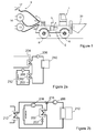
- FIG. 1 illustrates an example of a battery powered vehicle 1, according to an embodiment.
- the battery powered vehicle comprises a battery 10.
- the battery may be capable of storing electrical energy to be supplied to one or more functions of the vehicle.
- the battery may be enclosed within an encasement for protecting the battery from damages.
- the electrical energy from the battery may be used to power transportation of goods and/or people by the vehicle.
- the battery may be lithium-ion battery.
- a refrigeration device 11 may be connected to the battery for refrigerating, i.e. cooling, the battery.
- the refrigeration device has a cooling power that is sufficient to refrigerate the battery, when the battery is discharged and is supplying electrical power to power operations of the vehicle.
- the refrigeration device may have a refrigerant circuit for circulating a refrigerant via the battery and a fluid-fluid heat exchanger connected to the refrigerant circuit.
- the fluid-fluid heat exchanger is connectable to an external refrigerant circuit for transferring heat between the refrigerant circuit and the external refrigerant circuit.
- the external refrigerant circuit may be the refrigerant circuit of a charging station 9. Both of the refrigerant circuits have fluid lines that contain a refrigerant that is moved within the fluid lines for transferring heat away from target that is being cooled.
- the refrigerants of the refrigerant circuits may be selected to provide a sufficient cooling power and they may be the same.
- the battery powered vehicle may comprise a carriage 2 that may be moved by means of drive equipment 3.
- the drive equipment 3 may comprise one or more drive motors 4 and one or more power transmission means 5 for transmitting drive power to one or more wheels 6.
- the drive power transmission may comprise a mechanical gear system and mechanical power transmission members or, alternatively, a hydraulic or electric drive power system may be used.
- the drive equipment may be connected to the battery for supplying electricity to the drive equipment from the battery.
- the connection may comprise an electrically conductive cable, shown by a dashed line in the Figure 1 between the battery and the drive equipment. Accordingly, the movement of the vehicle may be powered by electricity from the battery. It should be appreciated that the vehicle may have also other power sources in addition to the battery.
- the battery powered vehicle may comprise a dump 20 and/or a drill for production operations of the vehicle.
- the productive operations may be mining operations, when the vehicle is a mining machine.
- the production operations may be powered by the drive equipment.
- the vehicle may be have a water system that is used for or is a part of the drill.
- the charging station may be located in an operational area 14 of the vehicle or in a service area of the vehicle.
- the operational area of the vehicle may be for example a mine.
- the charging station may comprise an electrical outlet 17 for charging the battery of the vehicle with electrical energy.
- the electrical outlet may be connected to the vehicle by at least one electrically conductive cable for charging the battery.
- the charging station may further comprise a connection 12, 13 for connecting a refrigerant circuit of the charging station to a fluid-fluid heat exchanger in the vehicle.
- the connection may be provided by an inlet connection 12 for feeding refrigerant to the fluid-fluid heat exchanger, and an outlet connection 13 for receiving heated refrigerant from the fluid-fluid heat exchanger.
- the inlet and outlet connections may be provided by hoses arranged on reels.
- the inlet and outlet connections of the charging station may be connected to connectors 15, 16 of the refrigerant circuit 11 of the vehicle for connecting the refrigerant circuit of the charging station to the fluid-fluid heat exchanger.
- the refrigerant circuit of the charging station may be connected to the vehicle for cooling the battery during charging of the battery. This allows dimensioning the refrigerant circuit of the vehicle for refrigeration of the battery, when the battery is not being charged and less cooling power is needed.
- the battery When the battery is not being charged, the battery may be discharging. When the battery is discharging, energy stored to the battery may be consumed. The power may be consumed to one or more functions of the vehicle, for example during driving of the vehicle.
- the refrigerant circuit of the charging station may be responsible for cooling the battery during charging of the battery.
- the refrigerant circuit of the charging station is dimensioned such that it has a higher cooling power than the refrigerant circuit of the vehicle.
- the dimensioning of the refrigerant circuits may comprise considerations on an amount of fluid flow in fluid lines and/or a type of refrigerant used.
- the charging station may be connected to a power source having a larger electrical power than the battery on-board the vehicle.
- the power source of the charging station may be for example an electrical grid or an electrical generator powered by a combustion engine. In this way more power is available for refrigeration of the battery during charging of the battery than during discharging of the battery. Since the refrigeration during charging is more efficient than during discharging, the battery may be charged quickly using a high charging power.
- the charging power may be higher than the power output of the battery, when the battery is discharged. In one example, a mean power output of the battery is 100kW during operation of the vehicle and the charging power is 800 kW, whereby it is possible to achieve an operating time of two hours for the battery, when the battery is charged for 15 minutes.
- refrigerant from the refrigerant circuit of the charging station is circulated via the fluid-fluid heat exchanger of the mining machine.
- the refrigerant circuit of the charging station may be connected to or be a part of a water supply line in a mine. Accordingly, water from the water supply line may serve as the refrigerant in the refrigerant circuit of the charging station.
- the water may circulate in a water system of the mine. The circulation of the water provides that water heated by the battery may be replaced by cooler water, whereby refrigeration of the charging station provided to batteries that are charged may be maintained even if the charging station would be used continuously.
- the battery powered vehicle may be a mining machine 1 for example a dumper, load haul dump, loader, drilling device, rock drilling rig or any other mining vehicle.
- the mining vehicle 1 may be equipped with one or more mining work devices which mining work device may be one or more of the following mining work devices: rock drilling machine, bolting machine, scaling device, injection device, blasthole charger, loading device, bucket, box, measuring device, or drilling, sealing and propellant feeding equipment used in small-charge excavation.
- FIGs 2a and 2b illustrate refrigerant circuits according to embodiments.
- the refrigerant circuits may be the refrigerant circuits of the charging station and the vehicle described in Figure 1 .
- the refrigerant circuits are connected in series.
- the refrigerant circuits are connected in parallel by a three-way valve 216.
- the parallel and series connection of the refrigerant circuits provide that the refrigerant circuit of the vehicle and the charging station are both connected to a fluid-fluid heat exchanger 202 such that refrigerant from the circuits may flow to the fluid-fluid heat exchanger.
- the refrigerant circuits are connected to the fluid-fluid heat exchanger during charging of the battery 210 of the vehicle such that the refrigerant from the refrigerant circuit of the charging station may cool down the battery.
- the refrigerant circuit of the charging station or the refrigerant circuit of the vehicle may be disconnected from the fluid-fluid heat exchanger such that the vehicle may be moved away from the charging station.
- the refrigerant circuits are described assuming that the fluid-fluid heat exchanger is on-board the vehicle, as a part of the refrigerant circuit of the vehicle.
- the fluid-fluid heat exchanger may be located in the charging station as a part of the refrigerant circuit of the charging station.
- the refrigerant circuits of the vehicle and the charging station comprise fluid lines that contain refrigerant that is moved by a pump 206 or a compressor 208 in the fluid lines.
- the refrigerant circuit of the vehicle may comprise a battery cooler 204.
- the battery cooler may be positioned within the battery such that heat may be conducted from the battery to the refrigerant within the fluid lines of the refrigerant circuit.
- the battery cooler may transfer heat from the battery, when the refrigerant circuit of the vehicle is not connected to the refrigerant circuit of the charging station, for example during driving of the vehicle.
- the fluid lines may feed the refrigerant inside the battery, where the refrigerant is passed between refrigeration plates inside the battery.
- the refrigeration plates inside the battery act as a heat sink. Refrigerant heated by the battery is directed to the battery cooler for transferring heat from the refrigerant.
- the battery cooler may be a heat pump for example.
- the refrigerant circuit of the charging station may comprise a cooling system.
- the refrigeration power of the refrigerant circuit of the charging station is greater than the refrigeration power of the vehicle's refrigerant circuit.
- the refrigerant circuit may be adapted to reach the cooling power by designing the components of the refrigerant circuit, e.g. the cooling system, fluid lines and the refrigerant to meet desired cooling power that is greater than the cooling power of the vehicle's refrigerant circuit.
- the cooling system may have a greater cooling power than the battery cooler.
- the refrigerants used in the refrigerant circuits may be different or of the same type.
- the cooling system may comprise a water supply line of a mine or the cooling system may be a part of a water supply line of a mine. In this way water from the water supply line of the mine may be used to cool down the battery during charging of the battery. After the water has been used to cool down the battery, for example after the water has passed the fluid-fluid heat exchanger, the water may be fed to a sewerage system. Alternatively or additionally the water may be directed after the fluid-fluid heat exchanger to a water system of the vehicle, e.g. a mining machine. In the water system of the mining machine the water may be used for flushing drilling holes and for removing or tying down dust, which may be particularly useful in continuous mining machines.
- the charging station, vehicle and sewerage system and their refrigerant circuits may be provided with appropriate connections, valves and/or piping for directing water from the fluid-fluid heat exchanger.
- water from a water system of the vehicle for example the mining machine, may be used to enhance cooling of the battery.
- the water system may be used in the mining machine for supplying water to one or more mining operations. Examples of the mining operations include drilling, for example.
- the water system may be used for flushing drilling holes and for removing or tying down dust, for example.
- the water from the water system of the mining machine may be fed to the refrigerant circuit of the mining machine for cooling down the battery continuously or at times, when the battery is operated at a high power.
- the battery may be operated at a high power, when the battery supplies a substantial part of the power, for example a drilling power, needed by the mining machine, or the battery is used for buffering input power of the mining machine.
- flow of the refrigerant in the cooling system of refrigerant circuit of the charging station may be controlled.
- the cooling system may comprise for example an evaporator 212 and optionally a condenser (not shown).
- the evaporator may cool down refrigerant from the fluid lines by air moving through the evaporator.
- the condenser may receive refrigerant in gas phase from the fluid lines. In the condenser, the refrigerant may be cooled down and converted to liquid phase. From the condenser the refrigerant may be fed back to the fluid lines.
- the refrigerant may be controlled to flow through the evaporator, when the refrigerant circuits of the vehicle and the charging station are not connected, and the refrigerant may be controlled to flow through the fluid-fluid heat exchanger, when the refrigerant circuits are connected via the fluid-fluid heat exchanger.
- the fluid-fluid heat exchanger may be connected the fluid lines behind a valve 203 such that flow of the refrigerant through the fluid-fluid heat exchanger may be controlled, for example switched on or off.
- the evaporator may be connected to the fluid lines behind a valve 213 such that flow of the refrigerant through the evaporator may be controlled, for example switched on or off.
- the valves may be located in upstream direction from the fluid-fluid heat exchanger and/or the evaporator.
- the upstream direction may refer to a direction against the flow of the refrigerant.
- flow of the refrigerant may be controlled such that the flow of the refrigerant through the fluid-fluid heat exchanger 202 may be switched off, when the refrigerant circuits of the vehicle and the charging station are not connected.
- the refrigerant circuits are not connected, for example, when the vehicle is not positioned at the charging station for charging the battery. When the battery is not charged, the vehicle may be moving as powered by the stored energy discharging from the battery. Accordingly, when the refrigerant circuits are not connected, the refrigerant circuit of the charging station may circulate the refrigerant via the evaporator 212 and the condenser to cool down the refrigerant.
- the refrigerant may be cooled down between charging operations of batteries, which may be charging operations of the same battery or charging operations of different batteries. Accordingly, when the flow of the refrigerant through the fluid-fluid heat exchanger is switched off, the flow of the refrigerant through the evaporator may be switched on.
- flow of the refrigerant may be controlled such that the flow of the refrigerant through the evaporator 212 may be switched off, when the vehicle is positioned at the charging station for charging the battery and the refrigerant circuits of the vehicle and the charging station are connected.
- the refrigerant circuits When the refrigerant circuits are connected the refrigerant circuit of the charging station may circulate the refrigerant via the fluid-fluid heat exchanger 202 and the condenser to cool down the refrigerant. Accordingly, when the flow of the refrigerant through the evaporator is switched off, the flow of the refrigerant through the fluid-fluid heat exchanger may be switched on.
- flow of the refrigerant in the cooling system of vehicle may be controlled.
- the refrigerant of the refrigerant circuit of the vehicle may be directed via the fluid-fluid heat exchanger, when the refrigerant circuit of the vehicle and the refrigerant circuit of the charging station are connected, for example during charging of the battery.
- the refrigerant circuits are not connected the refrigerant of the refrigerant circuit of the vehicle may be directed to the battery cooler.
- the controlling may be provided by the three-way valve 216.
- refrigerant of the refrigerant circuit of the vehicle may be directed via the fluid-fluid heat exchanger from different portions of the refrigerant circuit of the vehicle.
- One of the portions may comprise the battery 210 and the other portion may comprise the battery cooler 204.
- the three-way valve may be used to direct the flow of refrigerant from the battery or battery cooler to the fluid-fluid heat exchanger.
- the refrigerant circuits of the vehicle and the charging station are connected, e.g. during the battery is charged, in order to cool down the refrigerant flowing through the fluid-fluid heat exchanger.
- refrigerant from the refrigerant circuit comprising the battery may be directed via the fluid-fluid heat exchanger and after the battery is charged, refrigerant from the portion of the refrigerant circuit comprising the battery cooler may be directed via the fluid-fluid heat exchanger. In this way the battery cooler may be cooled down before the refrigerant circuits are disconnected and the vehicle is moved away from the charging station to perform its tasks.
- An embodiment comprises an apparatus, for example a mining machine or a charging station, comprising at least one processor, memory and a computer program code, wherein the at least one memory and the computer program code are configured to, with the at least one processor, cause the apparatus perform one or more functions or steps of an embodiment.
- One or more functions described in the embodiments above and related to for example control of refrigerant in one or more refrigerant circuits may be implemented by control valves, e.g. two or three-way valves, that are electronically or manually controlled.
- One or more valves may be controlled by a common controller or the valves may be controlled by separate controllers.
- a controller may refer to a processor.
- the processor may be connected to a memory and a communications part electrically.
- the memory may store computer program code that when executed by the processor causes performing one or more functions or steps of an embodiment.
- the communications part may be a an electrical interface, connector or a communications module that is capable of obtaining electrical signals, commands and/or messages from the processor to one or more control valves.
- the communications may comprise digital or analogue communications.
- the communications may be wired or wireless communications.
- the communications may be implemented by various communications protocols and technologies, for example Ethernet, IEEE 802.11 based Wireless Local Area Network, Internet Protocol, Hart and Profibus.
- One or more sensors may be connected to the communications part such that data from the sensors may be used to in controlling the valves.
- Embodiments as described may also be carried out in the form of a computer process defined by a computer program.
- the computer program may be in source code form, object code form, or in some intermediate form, and it may be stored in some sort of carrier, which may be any entity or device capable of carrying the program.
- the computer program may be stored on a computer program distribution medium readable by a computer or a processor.
- the computer program medium may be, for example but not limited to, a record medium, computer memory, read-only memory, electrical carrier signal, telecommunications signal, and software distribution package, for example.
- the processor may be a computer processor, application-specific integrated circuit (ASIC), field-programmable gate array (FPGA), and/or any other hardware component that has been programmed in such a way to carry out one or more functions of an embodiment.
- ASIC application-specific integrated circuit
- FPGA field-programmable gate array
- the memory may include volatile and/or non- volatile memory and typically stores content, data, or the like.
- the memory may store computer program code such as software applications or operating systems, information, data, content, or the like for the processor to perform steps associated with operation of the apparatus in accordance with embodiments.
- the memory may be, for example, random access memory (RAM), a hard drive, or other fixed data memory or storage device. Further, the memory, or part of it, may be removable memory detachably connected to the control unit.
- One advantage of the invention is that the heat caused when charging the battery can be feeded out of the mine via the water supply lines in the mine.
Landscapes
- Engineering & Computer Science (AREA)
- Power Engineering (AREA)
- Mechanical Engineering (AREA)
- General Chemical & Material Sciences (AREA)
- Electrochemistry (AREA)
- Chemical Kinetics & Catalysis (AREA)
- Chemical & Material Sciences (AREA)
- Manufacturing & Machinery (AREA)
- Life Sciences & Earth Sciences (AREA)
- Transportation (AREA)
- Sustainable Energy (AREA)
- Sustainable Development (AREA)
- Mining & Mineral Resources (AREA)
- Geology (AREA)
- Environmental & Geological Engineering (AREA)
- General Life Sciences & Earth Sciences (AREA)
- Fluid Mechanics (AREA)
- Geochemistry & Mineralogy (AREA)
- Physics & Mathematics (AREA)
- Electric Propulsion And Braking For Vehicles (AREA)
- Devices That Are Associated With Refrigeration Equipment (AREA)
- Separation By Low-Temperature Treatments (AREA)
- Charge And Discharge Circuits For Batteries Or The Like (AREA)
- Secondary Cells (AREA)
Abstract
Description
- The present invention relates to refrigeration of battery, and particularly refrigeration of battery in a mining machine.
- A battery for storing electrical energy should be operated in a temperature range that supports a long lifetime of the battery. When a battery is charged electrical energy is stored to the battery for later use. When the energy stored to the battery is used to supply power to an appliance, e.g. an electrical motor, the battery is discharged.
- A typical operating temperature for a lithium-ion battery is between 0-45 °C. If the temperature exceeds 45 °C, the battery may be degraded. When the temperature of the battery is higher than 45 °C, electrolyte inside the battery starts to degrade, which may cause pressure inside battery cells. The pressure may accumulate inside the battery and it may be discharged from the battery along with the electrolyte, whereby personnel and equipment nearby the battery may be in danger.
- A battery typically used in a mining vehicle may supply an electrical power of 100kW, when the vehicle is operated. After the battery is discharged it has to be replaced with a new one or charged. During charging of the battery, the vehicle is out of production, whereby its efficiency is decreased. The battery may be charged fast if a significantly higher power, for example 800kW, is used to charge the battery. However, the high charging power may cause the battery to heat up significantly more than during operation of the mining vehicle and discharging of the battery.
- An object of the present invention is to provide a mining machine and a charging station comprising refrigerant circuits so as to so as to alleviate the above disadvantages. The objects of the invention are achieved by a mining machine and a charging station, which are characterized by what is stated in the independent claims. The preferred embodiments of the invention are disclosed in the dependent claims.
- An advantage of the mining machine and charging station according to the present invention is that the battery may be cooled down by different refrigerant circuits. A refrigerant circuit providing a suitable cooling power may be used during charging and another refrigerant circuit may be used during operation of the mining machine. This allows dimensioning the refrigerant circuits according to the need for cooling power that may vary significantly between the charging of the battery and discharging of the battery.
- In some embodiments, the battery may be cooled down by a refrigerant circuit having a smaller cooling power, when the battery is not being charged, than a refrigerant circuit used to cool down the battery during charging of the battery.
- In the following the invention will be described in greater detail by means of preferred embodiments with reference to the accompanying drawings, in which
-
Figure 1 illustrates an example of a battery powered vehicle, according to an embodiment; -
Figures 2a and 2b illustrate refrigerant circuits according to embodiments. -
Figure 1 illustrates an example of a battery powered vehicle 1, according to an embodiment. The battery powered vehicle comprises abattery 10. The battery may be capable of storing electrical energy to be supplied to one or more functions of the vehicle. The battery may be enclosed within an encasement for protecting the battery from damages. The electrical energy from the battery may be used to power transportation of goods and/or people by the vehicle. In an embodiment the battery may be lithium-ion battery. - A
refrigeration device 11 may be connected to the battery for refrigerating, i.e. cooling, the battery. Preferably, the refrigeration device has a cooling power that is sufficient to refrigerate the battery, when the battery is discharged and is supplying electrical power to power operations of the vehicle. - The refrigeration device may have a refrigerant circuit for circulating a refrigerant via the battery and a fluid-fluid heat exchanger connected to the refrigerant circuit. The fluid-fluid heat exchanger is connectable to an external refrigerant circuit for transferring heat between the refrigerant circuit and the external refrigerant circuit. The external refrigerant circuit may be the refrigerant circuit of a charging station 9. Both of the refrigerant circuits have fluid lines that contain a refrigerant that is moved within the fluid lines for transferring heat away from target that is being cooled. The refrigerants of the refrigerant circuits may be selected to provide a sufficient cooling power and they may be the same.
- The battery powered vehicle may comprise a
carriage 2 that may be moved by means of drive equipment 3. The drive equipment 3 may comprise one or more drive motors 4 and one or more power transmission means 5 for transmitting drive power to one ormore wheels 6. The drive power transmission may comprise a mechanical gear system and mechanical power transmission members or, alternatively, a hydraulic or electric drive power system may be used. The drive equipment may be connected to the battery for supplying electricity to the drive equipment from the battery. The connection may comprise an electrically conductive cable, shown by a dashed line in theFigure 1 between the battery and the drive equipment. Accordingly, the movement of the vehicle may be powered by electricity from the battery. It should be appreciated that the vehicle may have also other power sources in addition to the battery. - The battery powered vehicle may comprise a
dump 20 and/or a drill for production operations of the vehicle. The productive operations may be mining operations, when the vehicle is a mining machine. The production operations may be powered by the drive equipment. The vehicle may be have a water system that is used for or is a part of the drill. - The charging station may be located in an
operational area 14 of the vehicle or in a service area of the vehicle. The operational area of the vehicle may be for example a mine. The charging station may comprise anelectrical outlet 17 for charging the battery of the vehicle with electrical energy. The electrical outlet may be connected to the vehicle by at least one electrically conductive cable for charging the battery. The charging station may further comprise aconnection inlet connection 12 for feeding refrigerant to the fluid-fluid heat exchanger, and anoutlet connection 13 for receiving heated refrigerant from the fluid-fluid heat exchanger. The inlet and outlet connections may be provided by hoses arranged on reels. The inlet and outlet connections of the charging station may be connected toconnectors refrigerant circuit 11 of the vehicle for connecting the refrigerant circuit of the charging station to the fluid-fluid heat exchanger. In this way the refrigerant circuit of the charging station may be connected to the vehicle for cooling the battery during charging of the battery. This allows dimensioning the refrigerant circuit of the vehicle for refrigeration of the battery, when the battery is not being charged and less cooling power is needed. When the battery is not being charged, the battery may be discharging. When the battery is discharging, energy stored to the battery may be consumed. The power may be consumed to one or more functions of the vehicle, for example during driving of the vehicle. - The refrigerant circuit of the charging station may be responsible for cooling the battery during charging of the battery. Preferably the refrigerant circuit of the charging station is dimensioned such that it has a higher cooling power than the refrigerant circuit of the vehicle. The dimensioning of the refrigerant circuits may comprise considerations on an amount of fluid flow in fluid lines and/or a type of refrigerant used.
- The charging station may be connected to a power source having a larger electrical power than the battery on-board the vehicle. The power source of the charging station may be for example an electrical grid or an electrical generator powered by a combustion engine. In this way more power is available for refrigeration of the battery during charging of the battery than during discharging of the battery. Since the refrigeration during charging is more efficient than during discharging, the battery may be charged quickly using a high charging power. The charging power may be higher than the power output of the battery, when the battery is discharged. In one example, a mean power output of the battery is 100kW during operation of the vehicle and the charging power is 800 kW, whereby it is possible to achieve an operating time of two hours for the battery, when the battery is charged for 15 minutes.
- During charging the battery via the electrical outlet, refrigerant from the refrigerant circuit of the charging station is circulated via the fluid-fluid heat exchanger of the mining machine.
- In an embodiment, the refrigerant circuit of the charging station may be connected to or be a part of a water supply line in a mine. Accordingly, water from the water supply line may serve as the refrigerant in the refrigerant circuit of the charging station. The water may circulate in a water system of the mine. The circulation of the water provides that water heated by the battery may be replaced by cooler water, whereby refrigeration of the charging station provided to batteries that are charged may be maintained even if the charging station would be used continuously.
- The battery powered vehicle may be a mining machine 1 for example a dumper, load haul dump, loader, drilling device, rock drilling rig or any other mining vehicle. The mining vehicle 1 may be equipped with one or more mining work devices which mining work device may be one or more of the following mining work devices: rock drilling machine, bolting machine, scaling device, injection device, blasthole charger, loading device, bucket, box, measuring device, or drilling, sealing and propellant feeding equipment used in small-charge excavation.
-
Figures 2a and 2b illustrate refrigerant circuits according to embodiments. The refrigerant circuits may be the refrigerant circuits of the charging station and the vehicle described inFigure 1 . InFigure 2a the refrigerant circuits are connected in series. InFigure 2b , the refrigerant circuits are connected in parallel by a three-way valve 216. The parallel and series connection of the refrigerant circuits provide that the refrigerant circuit of the vehicle and the charging station are both connected to a fluid-fluid heat exchanger 202 such that refrigerant from the circuits may flow to the fluid-fluid heat exchanger. Preferably, the refrigerant circuits are connected to the fluid-fluid heat exchanger during charging of thebattery 210 of the vehicle such that the refrigerant from the refrigerant circuit of the charging station may cool down the battery. - It should be appreciated that, when the battery is not charged the refrigerant circuit of the charging station or the refrigerant circuit of the vehicle may be disconnected from the fluid-fluid heat exchanger such that the vehicle may be moved away from the charging station.
- In the following description of
Figures 2a and 2b the refrigerant circuits are described assuming that the fluid-fluid heat exchanger is on-board the vehicle, as a part of the refrigerant circuit of the vehicle. However, in an embodiment the fluid-fluid heat exchanger may be located in the charging station as a part of the refrigerant circuit of the charging station. - The refrigerant circuits of the vehicle and the charging station comprise fluid lines that contain refrigerant that is moved by a
pump 206 or acompressor 208 in the fluid lines. - The refrigerant circuit of the vehicle may comprise a
battery cooler 204. The battery cooler may be positioned within the battery such that heat may be conducted from the battery to the refrigerant within the fluid lines of the refrigerant circuit. The battery cooler may transfer heat from the battery, when the refrigerant circuit of the vehicle is not connected to the refrigerant circuit of the charging station, for example during driving of the vehicle. The fluid lines may feed the refrigerant inside the battery, where the refrigerant is passed between refrigeration plates inside the battery. The refrigeration plates inside the battery act as a heat sink. Refrigerant heated by the battery is directed to the battery cooler for transferring heat from the refrigerant. The battery cooler may be a heat pump for example. - The refrigerant circuit of the charging station may comprise a cooling system. Preferably the refrigeration power of the refrigerant circuit of the charging station is greater than the refrigeration power of the vehicle's refrigerant circuit. The refrigerant circuit may be adapted to reach the cooling power by designing the components of the refrigerant circuit, e.g. the cooling system, fluid lines and the refrigerant to meet desired cooling power that is greater than the cooling power of the vehicle's refrigerant circuit. In one example, the cooling system may have a greater cooling power than the battery cooler. The refrigerants used in the refrigerant circuits may be different or of the same type. The cooling system may comprise a water supply line of a mine or the cooling system may be a part of a water supply line of a mine. In this way water from the water supply line of the mine may be used to cool down the battery during charging of the battery. After the water has been used to cool down the battery, for example after the water has passed the fluid-fluid heat exchanger, the water may be fed to a sewerage system. Alternatively or additionally the water may be directed after the fluid-fluid heat exchanger to a water system of the vehicle, e.g. a mining machine. In the water system of the mining machine the water may be used for flushing drilling holes and for removing or tying down dust, which may be particularly useful in continuous mining machines. The charging station, vehicle and sewerage system and their refrigerant circuits may be provided with appropriate connections, valves and/or piping for directing water from the fluid-fluid heat exchanger. In an embodiment, water from a water system of the vehicle, for example the mining machine, may be used to enhance cooling of the battery. The water system may be used in the mining machine for supplying water to one or more mining operations. Examples of the mining operations include drilling, for example. The water system may be used for flushing drilling holes and for removing or tying down dust, for example. The water from the water system of the mining machine may be fed to the refrigerant circuit of the mining machine for cooling down the battery continuously or at times, when the battery is operated at a high power. The battery may be operated at a high power, when the battery supplies a substantial part of the power, for example a drilling power, needed by the mining machine, or the battery is used for buffering input power of the mining machine.
- In an embodiment, flow of the refrigerant in the cooling system of refrigerant circuit of the charging station may be controlled. The cooling system may comprise for example an
evaporator 212 and optionally a condenser (not shown). The evaporator may cool down refrigerant from the fluid lines by air moving through the evaporator. The condenser may receive refrigerant in gas phase from the fluid lines. In the condenser, the refrigerant may be cooled down and converted to liquid phase. From the condenser the refrigerant may be fed back to the fluid lines. - The refrigerant may be controlled to flow through the evaporator, when the refrigerant circuits of the vehicle and the charging station are not connected, and the refrigerant may be controlled to flow through the fluid-fluid heat exchanger, when the refrigerant circuits are connected via the fluid-fluid heat exchanger.
- The fluid-fluid heat exchanger may be connected the fluid lines behind a
valve 203 such that flow of the refrigerant through the fluid-fluid heat exchanger may be controlled, for example switched on or off. The evaporator may be connected to the fluid lines behind a valve 213 such that flow of the refrigerant through the evaporator may be controlled, for example switched on or off. The valves may be located in upstream direction from the fluid-fluid heat exchanger and/or the evaporator. The upstream direction may refer to a direction against the flow of the refrigerant. - In one example, flow of the refrigerant may be controlled such that the flow of the refrigerant through the fluid-
fluid heat exchanger 202 may be switched off, when the refrigerant circuits of the vehicle and the charging station are not connected. The refrigerant circuits are not connected, for example, when the vehicle is not positioned at the charging station for charging the battery. When the battery is not charged, the vehicle may be moving as powered by the stored energy discharging from the battery. Accordingly, when the refrigerant circuits are not connected, the refrigerant circuit of the charging station may circulate the refrigerant via theevaporator 212 and the condenser to cool down the refrigerant. In this way the refrigerant may be cooled down between charging operations of batteries, which may be charging operations of the same battery or charging operations of different batteries. Accordingly, when the flow of the refrigerant through the fluid-fluid heat exchanger is switched off, the flow of the refrigerant through the evaporator may be switched on. - In one example, flow of the refrigerant may be controlled such that the flow of the refrigerant through the
evaporator 212 may be switched off, when the vehicle is positioned at the charging station for charging the battery and the refrigerant circuits of the vehicle and the charging station are connected. When the refrigerant circuits are connected the refrigerant circuit of the charging station may circulate the refrigerant via the fluid-fluid heat exchanger 202 and the condenser to cool down the refrigerant. Accordingly, when the flow of the refrigerant through the evaporator is switched off, the flow of the refrigerant through the fluid-fluid heat exchanger may be switched on. - In an embodiment, flow of the refrigerant in the cooling system of vehicle may be controlled. The refrigerant of the refrigerant circuit of the vehicle may be directed via the fluid-fluid heat exchanger, when the refrigerant circuit of the vehicle and the refrigerant circuit of the charging station are connected, for example during charging of the battery. On the other hand, when the refrigerant circuits are not connected the refrigerant of the refrigerant circuit of the vehicle may be directed to the battery cooler. The controlling may be provided by the three-
way valve 216. - In an embodiment, refrigerant of the refrigerant circuit of the vehicle may be directed via the fluid-fluid heat exchanger from different portions of the refrigerant circuit of the vehicle. One of the portions may comprise the
battery 210 and the other portion may comprise thebattery cooler 204. The three-way valve may be used to direct the flow of refrigerant from the battery or battery cooler to the fluid-fluid heat exchanger. The refrigerant circuits of the vehicle and the charging station are connected, e.g. during the battery is charged, in order to cool down the refrigerant flowing through the fluid-fluid heat exchanger. - In an embodiment, during charging of the battery refrigerant from the refrigerant circuit comprising the battery may be directed via the fluid-fluid heat exchanger and after the battery is charged, refrigerant from the portion of the refrigerant circuit comprising the battery cooler may be directed via the fluid-fluid heat exchanger. In this way the battery cooler may be cooled down before the refrigerant circuits are disconnected and the vehicle is moved away from the charging station to perform its tasks.
- An embodiment comprises an apparatus, for example a mining machine or a charging station, comprising at least one processor, memory and a computer program code, wherein the at least one memory and the computer program code are configured to, with the at least one processor, cause the apparatus perform one or more functions or steps of an embodiment.
- One or more functions described in the embodiments above and related to for example control of refrigerant in one or more refrigerant circuits may be implemented by control valves, e.g. two or three-way valves, that are electronically or manually controlled. One or more valves may be controlled by a common controller or the valves may be controlled by separate controllers. A controller may refer to a processor. The processor may be connected to a memory and a communications part electrically. The memory may store computer program code that when executed by the processor causes performing one or more functions or steps of an embodiment.
- The communications part may be a an electrical interface, connector or a communications module that is capable of obtaining electrical signals, commands and/or messages from the processor to one or more control valves. The communications may comprise digital or analogue communications. The communications may be wired or wireless communications. The communications may be implemented by various communications protocols and technologies, for example Ethernet, IEEE 802.11 based Wireless Local Area Network, Internet Protocol, Hart and Profibus. One or more sensors may be connected to the communications part such that data from the sensors may be used to in controlling the valves.
- Embodiments as described may also be carried out in the form of a computer process defined by a computer program. The computer program may be in source code form, object code form, or in some intermediate form, and it may be stored in some sort of carrier, which may be any entity or device capable of carrying the program. For example, the computer program may be stored on a computer program distribution medium readable by a computer or a processor. The computer program medium may be, for example but not limited to, a record medium, computer memory, read-only memory, electrical carrier signal, telecommunications signal, and software distribution package, for example.
- The processor may be a computer processor, application-specific integrated circuit (ASIC), field-programmable gate array (FPGA), and/or any other hardware component that has been programmed in such a way to carry out one or more functions of an embodiment.
- The memory may include volatile and/or non- volatile memory and typically stores content, data, or the like. For example, the memory may store computer program code such as software applications or operating systems, information, data, content, or the like for the processor to perform steps associated with operation of the apparatus in accordance with embodiments. In the illustrated embodiment, the memory may be, for example, random access memory (RAM), a hard drive, or other fixed data memory or storage device. Further, the memory, or part of it, may be removable memory detachably connected to the control unit.
- It will be obvious to a person skilled in the art that, as the technology advances, the inventive concept can be implemented in various ways. The invention and its embodiments are not limited to the examples described above but may vary within the scope of the claims. One advantage of the invention is that the heat caused when charging the battery can be feeded out of the mine via the water supply lines in the mine.
Claims (13)
- A mining machine comprising:a battery for storing electrical energy;a refrigerant circuit for circulating a refrigerant via the battery; anda connection for connecting the refrigerant circuit to a refrigerant circuit of a charging station via a fluid-fluid heat exchanger.
- A mining machine according to claim 1, wherein the mining machine comprises the fluid-fluid heat exchanger and the fluid-fluid heat exchanger is connectable to the refrigerant circuit of the charging station for transferring heat between the refrigerant circuit of the mining machine and the refrigerant circuit of the charging station, when the refrigerant circuits are connected via the fluid-fluid heat exchanger.
- A mining machine according to claim 1 or 2, wherein during charging of the battery, the refrigerant of the refrigerant circuit of the mining machine is directed via the fluid-fluid heat exchanger for transferring heat from the battery to the refrigerant circuit of the charging station connected to the fluid-fluid heat exchanger.
- A mining machine according to claim 1, 2 or 3, wherein the battery is cooled by a battery cooler of the refrigerant circuit of the mining machine, when power stored to the battery is consumed by the mining machine.
- A mining machine to any one of claims 1, 2, 3 or 4, wherein the refrigerant of the refrigerant circuit of the mining machine is directed via the fluid-fluid heat exchanger from at least one portion of the refrigerant circuit of the mining machine, wherein a first portion of the refrigerant circuit of the mining machine comprises the battery and a second portion of the refrigerant circuit of the mining machine comprises the battery cooler, when the refrigerant circuit of the charging station is connected to the fluid-fluid heat exchanger.
- A mining machine according to claim 5, wherein during charging of the battery refrigerant from the first portion of the refrigerant circuit of the mining machine is directed via the fluid-fluid heat exchanger and after the battery is charged, refrigerant from the second portion of the refrigerant circuit of the mining machine is directed via the fluid-fluid heat exchanger.
- A mining machine according to any one of the preceding claims, wherein the mining machine comprises a water system for mining operations and the water from the water system for mining operations is fed to the refrigerant circuit of the mining machine for cooling down the battery continuously or at times, when the battery is operated at a high power such that a substantial part of the power, for example a drilling power, needed by the mining machine, is supplied by the battery, or the battery is used for buffering input power of the mining machine.
- A mining machine according to any one of the preceding claims, wherein the battery is a lithium-ion battery.
- A charging station comprising:an electrical outlet for charging a battery with electrical energy;a refrigerant circuit;anda connection for connecting the refrigerant circuit via a fluid-fluid heat exchanger to another refrigerant circuit connected to the battery of a mining machine.
- A charging station according to claim 9, wherein the fluid-fluid heat exchanger is located in the charging station or in a mining machine according to any one of claims 1 to 8.
- A charging station according to claim 9 or 10, wherein during charging of the battery via the electrical outlet, refrigerant from the refrigerant circuit of the charging station is circulated via the fluid-fluid heat exchanger for transferring heat between the refrigerant circuit connected to the battery of the mining machine and the refrigerant circuit of the charging station, when the refrigerant circuits are connected via the fluid-fluid heat exchanger.
- A charging station according to any one of claims 9 to 11, wherein the refrigerant circuit of the charging station comprises an evaporator, wherein the refrigerant in the refrigerant circuit of the charging station is controlled to flow through the evaporator, when the refrigerant circuits are not connected via the fluid-fluid heat exchanger, and the refrigerant in the refrigerant circuit of the charging station is controlled to flow through the fluid-fluid heat exchanger, when the refrigerant circuits are connected via the fluid-fluid heat exchanger.
- A charging station according to any one of claims 9 to 12, wherein the refrigerant circuit of the charging station is connected to or is a part of a water supply line in a mine.
Priority Applications (6)
| Application Number | Priority Date | Filing Date | Title |
|---|---|---|---|
| FIEP14192036.3T FI3017990T3 (en) | 2014-11-06 | 2014-11-06 | Mining machine and charging station comprising refrigeration circuits |
| EP14192036.3A EP3017990B1 (en) | 2014-11-06 | 2014-11-06 | Mining machine and charging station comprising refrigeration circuits |
| PL14192036.3T PL3017990T3 (en) | 2014-11-06 | 2014-11-06 | Mining machine and charging station comprising refrigeration circuits |
| CA2902691A CA2902691C (en) | 2014-11-06 | 2015-09-02 | Mining machine and charging station comprising refrigeration circuits |
| ZA2015/08183A ZA201508183B (en) | 2014-11-06 | 2015-11-05 | Mining machine and charging station comprising refrigeration circuits |
| US14/933,935 US10259333B2 (en) | 2014-11-06 | 2015-11-05 | Mining machine and charging station comprising refrigeration circuits |
Applications Claiming Priority (1)
| Application Number | Priority Date | Filing Date | Title |
|---|---|---|---|
| EP14192036.3A EP3017990B1 (en) | 2014-11-06 | 2014-11-06 | Mining machine and charging station comprising refrigeration circuits |
Publications (2)
| Publication Number | Publication Date |
|---|---|
| EP3017990A1 true EP3017990A1 (en) | 2016-05-11 |
| EP3017990B1 EP3017990B1 (en) | 2023-05-03 |
Family
ID=51870887
Family Applications (1)
| Application Number | Title | Priority Date | Filing Date |
|---|---|---|---|
| EP14192036.3A Active EP3017990B1 (en) | 2014-11-06 | 2014-11-06 | Mining machine and charging station comprising refrigeration circuits |
Country Status (6)
| Country | Link |
|---|---|
| US (1) | US10259333B2 (en) |
| EP (1) | EP3017990B1 (en) |
| CA (1) | CA2902691C (en) |
| FI (1) | FI3017990T3 (en) |
| PL (1) | PL3017990T3 (en) |
| ZA (1) | ZA201508183B (en) |
Cited By (5)
| Publication number | Priority date | Publication date | Assignee | Title |
|---|---|---|---|---|
| CN108394308A (en) * | 2018-05-18 | 2018-08-14 | 中山市聚云软件科技有限公司 | A kind of integral type waterproof intelligence community charging pile |
| EP3565083A1 (en) * | 2018-05-04 | 2019-11-06 | United Technologies Corporation | Battery cooling architecture for a vehicle |
| CN110504509A (en) * | 2018-05-18 | 2019-11-26 | 大众汽车有限公司 | Method for regulating the temperature of a battery |
| AU2020201606B2 (en) * | 2017-07-12 | 2021-08-05 | Dr. Ing. H.C.F. Porsche Aktiengesellschaft | Cooling unit for a charging column, and charging column having a cooling unit |
| WO2023247317A1 (en) * | 2022-06-21 | 2023-12-28 | Man Truck & Bus Se | Heat transfer between a motor vehicle and an infrastructure |
Families Citing this family (18)
| Publication number | Priority date | Publication date | Assignee | Title |
|---|---|---|---|---|
| EP3037297B1 (en) * | 2014-12-22 | 2019-03-06 | Sandvik Mining and Construction Oy | Mining vehicle and method for its energy supply |
| US10717367B1 (en) | 2016-03-11 | 2020-07-21 | Apple Inc. | Thermal control systems for battery charging |
| PL3257700T3 (en) * | 2016-06-17 | 2020-02-28 | Sandvik Mining And Construction Oy | Charging connector arrangement having sensor, in underground vehicle |
| EP3257699B1 (en) * | 2016-06-17 | 2021-02-24 | Sandvik Mining and Construction Oy | Charging mode adaptation and notification arrangement in underground mining vehicle |
| FR3067860B1 (en) * | 2017-06-15 | 2021-04-16 | Airbus Group Sas | SYSTEM FOR CHARGING AT LEAST ONE BATTERY OF ACCUMULATORS OF A VEHICLE AND PROCESS FOR MANAGING THE RECHARGE OF SUCH AT LEAST ONE BATTERY |
| CN107804187A (en) * | 2017-10-30 | 2018-03-16 | 江苏宝奥兰空调设备有限公司 | A kind of charging pile system |
| GB2582261B (en) | 2019-03-01 | 2023-06-21 | Bamford Excavators Ltd | Working machine |
| GB2582260B (en) | 2019-03-01 | 2023-03-08 | Bamford Excavators Ltd | Working machine |
| GB201903399D0 (en) | 2019-03-01 | 2019-04-24 | Bamford Excavators Ltd | A working machine and a controller |
| US11710868B2 (en) | 2020-06-03 | 2023-07-25 | Toyota Motor Engineering & Manufacturing North America, Inc. | Battery pack and a method for charging and cooling the battery pack using an external cooling device |
| JP7359116B2 (en) * | 2020-09-16 | 2023-10-11 | 株式会社豊田自動織機 | Feeding systems, industrial vehicles and feeding machines |
| KR20230033113A (en) * | 2021-08-27 | 2023-03-08 | 현대자동차주식회사 | Coolant circulation system of vehicle |
| US11961984B2 (en) * | 2021-09-22 | 2024-04-16 | Caterpillar Paving Products Inc. | Subsystem thermal transfer for working machine |
| EP4413227B1 (en) * | 2021-10-08 | 2026-04-29 | Epiroc Rock Drills Aktiebolag | Rock drilling rig, system of mining equipment and method therefor |
| KR20230135937A (en) * | 2022-03-17 | 2023-09-26 | 현대자동차주식회사 | Coolant circulation system for mobility |
| US11993397B1 (en) * | 2023-03-10 | 2024-05-28 | Beta Air, Llc | System and a method for preconditioning a power source of an electric aircraft |
| DE102023124653A1 (en) * | 2023-09-13 | 2025-03-13 | TERRA AG für Tiefbautechnik | Device and method for creating or expanding a borehole in the ground |
| CN118205421B (en) * | 2024-05-21 | 2024-07-23 | 国网(山东)电动汽车服务有限公司 | A grid heat sink suitable for liquid-cooled pre-installed charging station and charging station thereof |
Citations (3)
| Publication number | Priority date | Publication date | Assignee | Title |
|---|---|---|---|---|
| US5909099A (en) * | 1996-08-07 | 1999-06-01 | Sumitomo Wiring Systems, Ltd. | Electric vehicle charging system including refrigerant system |
| US20120043935A1 (en) * | 2011-07-25 | 2012-02-23 | Lightening Energy | Station for rapidly charging an electric vehicle battery |
| DE102011082565A1 (en) * | 2011-09-13 | 2013-03-14 | Sb Limotive Company Ltd. | Electrical Charging system for charging lithium-ion battery of e.g. hybrid vehicle, has heat exchanger whose components are respectively integrated into internal refrigerant circuit of battery module and external cooling system |
Family Cites Families (18)
| Publication number | Priority date | Publication date | Assignee | Title |
|---|---|---|---|---|
| JP4162026B2 (en) * | 2006-09-29 | 2008-10-08 | トヨタ自動車株式会社 | Vehicle charging system, vehicle charging device and electric vehicle |
| JP4715708B2 (en) * | 2006-10-03 | 2011-07-06 | トヨタ自動車株式会社 | Electric vehicle and vehicle charging system |
| FR2934087A3 (en) | 2008-07-21 | 2010-01-22 | Renault Sas | SYSTEM AND METHOD FOR COOLING A BATTERY OF AN ELECTRIC VEHICLE, BATTERY AND COOLING STATION OF A BATTERY |
| AU2010338146B2 (en) * | 2009-12-28 | 2013-11-07 | Sandvik Mining And Construction Oy | Mining vehicle and method for its energy supply |
| DE102011000573A1 (en) | 2011-02-09 | 2012-08-09 | Dr. Ing. H.C. F. Porsche Aktiengesellschaft | Hybrid or electric car has fluid-cooled component which is connected to cooling circuit through leakage-proof connectors |
| JP2012256790A (en) | 2011-06-10 | 2012-12-27 | Toyota Motor Corp | Cooling structure of lamination battery |
| US9786961B2 (en) | 2011-07-25 | 2017-10-10 | Lightening Energy | Rapid charging electric vehicle and method and apparatus for rapid charging |
| US8174235B2 (en) * | 2011-07-25 | 2012-05-08 | Lightening Energy | System and method for recharging electric vehicle batteries |
| US10340709B2 (en) * | 2011-07-29 | 2019-07-02 | Lightening Energy | Electric battery rapid recharging system including a mobile charging station having a coolant supply line and an electrical supply line |
| DE102011082566A1 (en) | 2011-09-13 | 2013-03-14 | Sb Limotive Company Ltd. | Electric charging system for battery-powered motor vehicle, has heat exchanger with two components that are positively connected, to provide mechanical interface between cooling system and battery module thermally conductive material |
| DE102011082991B4 (en) | 2011-09-20 | 2021-08-12 | Robert Bosch Gmbh | Battery housing, in particular for lithium-ion cells, with a temperature control medium distribution system, battery and motor vehicle |
| DE102011086569A1 (en) * | 2011-11-17 | 2013-05-23 | Sb Limotive Company Ltd. | Method for controlling the temperature of a vehicle with at least partial electric drive, vehicle and charging station |
| DE102012213855A1 (en) * | 2012-08-06 | 2014-02-06 | Robert Bosch Gmbh | Battery charging system for charging motor vehicle in e.g. public area, has battery arranged in vehicle, and charging station comprising tempering body in which tempering medium is accommodated, where battery comprises cooling elements |
| DE102014203859A1 (en) * | 2013-04-18 | 2014-10-23 | Robert Bosch Gmbh | A method for controlling the temperature of a traction battery disposed in a vehicle during a charging process at a charging station and charging station for carrying out such a method |
| US9321362B2 (en) * | 2014-02-05 | 2016-04-26 | Tesia Motors, Inc. | Cooling of charging cable |
| US9527403B2 (en) * | 2014-04-29 | 2016-12-27 | Tesla Motors, Inc. | Charging station providing thermal conditioning of electric vehicle during charging session |
| EP3025890B1 (en) * | 2014-11-27 | 2018-02-28 | Sandvik Mining and Construction Oy | Cooling system and method |
| DE102015112347A1 (en) * | 2015-07-29 | 2017-02-02 | Dr. Ing. H.C. F. Porsche Aktiengesellschaft | Charging station with a charging cable |
-
2014
- 2014-11-06 EP EP14192036.3A patent/EP3017990B1/en active Active
- 2014-11-06 FI FIEP14192036.3T patent/FI3017990T3/en active
- 2014-11-06 PL PL14192036.3T patent/PL3017990T3/en unknown
-
2015
- 2015-09-02 CA CA2902691A patent/CA2902691C/en active Active
- 2015-11-05 ZA ZA2015/08183A patent/ZA201508183B/en unknown
- 2015-11-05 US US14/933,935 patent/US10259333B2/en active Active
Patent Citations (3)
| Publication number | Priority date | Publication date | Assignee | Title |
|---|---|---|---|---|
| US5909099A (en) * | 1996-08-07 | 1999-06-01 | Sumitomo Wiring Systems, Ltd. | Electric vehicle charging system including refrigerant system |
| US20120043935A1 (en) * | 2011-07-25 | 2012-02-23 | Lightening Energy | Station for rapidly charging an electric vehicle battery |
| DE102011082565A1 (en) * | 2011-09-13 | 2013-03-14 | Sb Limotive Company Ltd. | Electrical Charging system for charging lithium-ion battery of e.g. hybrid vehicle, has heat exchanger whose components are respectively integrated into internal refrigerant circuit of battery module and external cooling system |
Cited By (8)
| Publication number | Priority date | Publication date | Assignee | Title |
|---|---|---|---|---|
| AU2020201606B2 (en) * | 2017-07-12 | 2021-08-05 | Dr. Ing. H.C.F. Porsche Aktiengesellschaft | Cooling unit for a charging column, and charging column having a cooling unit |
| US11148534B2 (en) | 2017-07-12 | 2021-10-19 | Dr. Ing. H.C. F. Porsche Aktiengesellschaft | Cooling unit for a charging column, and charging column having a cooling unit |
| EP3565083A1 (en) * | 2018-05-04 | 2019-11-06 | United Technologies Corporation | Battery cooling architecture for a vehicle |
| US11024894B2 (en) | 2018-05-04 | 2021-06-01 | Raytheon Technologies Corporation | Cooling architecture for a vehicle |
| CN108394308A (en) * | 2018-05-18 | 2018-08-14 | 中山市聚云软件科技有限公司 | A kind of integral type waterproof intelligence community charging pile |
| CN110504509A (en) * | 2018-05-18 | 2019-11-26 | 大众汽车有限公司 | Method for regulating the temperature of a battery |
| CN110504509B (en) * | 2018-05-18 | 2023-01-24 | 大众汽车有限公司 | Method for regulating the temperature of a battery |
| WO2023247317A1 (en) * | 2022-06-21 | 2023-12-28 | Man Truck & Bus Se | Heat transfer between a motor vehicle and an infrastructure |
Also Published As
| Publication number | Publication date |
|---|---|
| CA2902691C (en) | 2017-09-19 |
| US20160134001A1 (en) | 2016-05-12 |
| US10259333B2 (en) | 2019-04-16 |
| CA2902691A1 (en) | 2016-05-06 |
| EP3017990B1 (en) | 2023-05-03 |
| PL3017990T3 (en) | 2023-11-06 |
| FI3017990T3 (en) | 2023-07-28 |
| ZA201508183B (en) | 2021-09-29 |
Similar Documents
| Publication | Publication Date | Title |
|---|---|---|
| EP3017990B1 (en) | Mining machine and charging station comprising refrigeration circuits | |
| US12388135B2 (en) | Hybrid hydrogen power module | |
| CN106553560B (en) | Electric vehicle charging station | |
| RU2527990C2 (en) | Drill rig, method of controlling temperature of its equipment of drive and liquid cooling system | |
| US12233683B2 (en) | Optimized power distribution to transport climate control systems amongst one or more electric supply equipment stations | |
| US20160156075A1 (en) | Cooling system and method | |
| JP2019009111A (en) | Charging system for electric vehicle | |
| US20150316301A1 (en) | Method and system for charging a transport refrigeration system | |
| EP3199780B1 (en) | Container-type compressed air storage power generation device | |
| CN105720664A (en) | Mining vehicle and method for energy supply thereof | |
| CN103153681A (en) | Method and system for eliminating fuel consumption during dynamic braking of electric drive machines | |
| AU2020201621A1 (en) | Configuration for battery powered electric drive load haul dump | |
| US20230073847A1 (en) | Electrical generator with an electrical bus connectable to different electrical power sources and different loads | |
| AU2017286315B2 (en) | Charging connector arrangement in underground vehicle | |
| JP2012140123A (en) | System and method for starting prime mover of power system | |
| US11577597B2 (en) | Control apparatus for vehicle cooling apparatus | |
| AU2012331036A1 (en) | Mining vehicle | |
| CN115503539A (en) | A charging system and method with battery temperature control | |
| CN116122121A (en) | Electric operation-based ground processing machine | |
| KR102594740B1 (en) | Transmission system operating apparatus for operating a transmission system using an energy transport vehicle equipped with a large battery pack and the operating method thereof | |
| US11661717B2 (en) | Pile press-in device and pile press-in method | |
| CN107303804A (en) | The structure generated electricity in optimization vehicle | |
| CN105848967B (en) | Method and system for dynamic power distribution in transport refrigeration systems | |
| US10844714B2 (en) | Tunnel boring machine operating arrangement and method |
Legal Events
| Date | Code | Title | Description |
|---|---|---|---|
| PUAI | Public reference made under article 153(3) epc to a published international application that has entered the european phase |
Free format text: ORIGINAL CODE: 0009012 |
|
| AK | Designated contracting states |
Kind code of ref document: A1 Designated state(s): AL AT BE BG CH CY CZ DE DK EE ES FI FR GB GR HR HU IE IS IT LI LT LU LV MC MK MT NL NO PL PT RO RS SE SI SK SM TR |
|
| AX | Request for extension of the european patent |
Extension state: BA ME |
|
| STAA | Information on the status of an ep patent application or granted ep patent |
Free format text: STATUS: REQUEST FOR EXAMINATION WAS MADE |
|
| 17P | Request for examination filed |
Effective date: 20161111 |
|
| RBV | Designated contracting states (corrected) |
Designated state(s): AL AT BE BG CH CY CZ DE DK EE ES FI FR GB GR HR HU IE IS IT LI LT LU LV MC MK MT NL NO PL PT RO RS SE SI SK SM TR |
|
| STAA | Information on the status of an ep patent application or granted ep patent |
Free format text: STATUS: EXAMINATION IS IN PROGRESS |
|
| 17Q | First examination report despatched |
Effective date: 20201127 |
|
| GRAP | Despatch of communication of intention to grant a patent |
Free format text: ORIGINAL CODE: EPIDOSNIGR1 |
|
| STAA | Information on the status of an ep patent application or granted ep patent |
Free format text: STATUS: GRANT OF PATENT IS INTENDED |
|
| RIC1 | Information provided on ipc code assigned before grant |
Ipc: H01M 10/613 20140101ALI20221103BHEP Ipc: H01M 10/60 20140101ALI20221103BHEP Ipc: H02J 7/14 20060101ALI20221103BHEP Ipc: B60L 3/00 20060101AFI20221103BHEP |
|
| INTG | Intention to grant announced |
Effective date: 20221205 |
|
| GRAS | Grant fee paid |
Free format text: ORIGINAL CODE: EPIDOSNIGR3 |
|
| GRAA | (expected) grant |
Free format text: ORIGINAL CODE: 0009210 |
|
| STAA | Information on the status of an ep patent application or granted ep patent |
Free format text: STATUS: THE PATENT HAS BEEN GRANTED |
|
| AK | Designated contracting states |
Kind code of ref document: B1 Designated state(s): AL AT BE BG CH CY CZ DE DK EE ES FI FR GB GR HR HU IE IS IT LI LT LU LV MC MK MT NL NO PL PT RO RS SE SI SK SM TR |
|
| REG | Reference to a national code |
Ref country code: GB Ref legal event code: FG4D |
|
| REG | Reference to a national code |
Ref country code: DE Ref legal event code: R096 Ref document number: 602014086816 Country of ref document: DE |
|
| REG | Reference to a national code |
Ref country code: AT Ref legal event code: REF Ref document number: 1564307 Country of ref document: AT Kind code of ref document: T Effective date: 20230515 Ref country code: CH Ref legal event code: EP |
|
| REG | Reference to a national code |
Ref country code: IE Ref legal event code: FG4D |
|
| P01 | Opt-out of the competence of the unified patent court (upc) registered |
Effective date: 20230603 |
|
| REG | Reference to a national code |
Ref country code: FI Ref legal event code: FGE |
|
| REG | Reference to a national code |
Ref country code: SE Ref legal event code: TRGR |
|
| REG | Reference to a national code |
Ref country code: LT Ref legal event code: MG9D |
|
| REG | Reference to a national code |
Ref country code: NL Ref legal event code: MP Effective date: 20230503 |
|
| REG | Reference to a national code |
Ref country code: AT Ref legal event code: MK05 Ref document number: 1564307 Country of ref document: AT Kind code of ref document: T Effective date: 20230503 |
|
| PG25 | Lapsed in a contracting state [announced via postgrant information from national office to epo] |
Ref country code: PT Free format text: LAPSE BECAUSE OF FAILURE TO SUBMIT A TRANSLATION OF THE DESCRIPTION OR TO PAY THE FEE WITHIN THE PRESCRIBED TIME-LIMIT Effective date: 20230904 Ref country code: NO Free format text: LAPSE BECAUSE OF FAILURE TO SUBMIT A TRANSLATION OF THE DESCRIPTION OR TO PAY THE FEE WITHIN THE PRESCRIBED TIME-LIMIT Effective date: 20230803 Ref country code: NL Free format text: LAPSE BECAUSE OF FAILURE TO SUBMIT A TRANSLATION OF THE DESCRIPTION OR TO PAY THE FEE WITHIN THE PRESCRIBED TIME-LIMIT Effective date: 20230503 Ref country code: ES Free format text: LAPSE BECAUSE OF FAILURE TO SUBMIT A TRANSLATION OF THE DESCRIPTION OR TO PAY THE FEE WITHIN THE PRESCRIBED TIME-LIMIT Effective date: 20230503 Ref country code: AT Free format text: LAPSE BECAUSE OF FAILURE TO SUBMIT A TRANSLATION OF THE DESCRIPTION OR TO PAY THE FEE WITHIN THE PRESCRIBED TIME-LIMIT Effective date: 20230503 |
|
| PG25 | Lapsed in a contracting state [announced via postgrant information from national office to epo] |
Ref country code: RS Free format text: LAPSE BECAUSE OF FAILURE TO SUBMIT A TRANSLATION OF THE DESCRIPTION OR TO PAY THE FEE WITHIN THE PRESCRIBED TIME-LIMIT Effective date: 20230503 Ref country code: LV Free format text: LAPSE BECAUSE OF FAILURE TO SUBMIT A TRANSLATION OF THE DESCRIPTION OR TO PAY THE FEE WITHIN THE PRESCRIBED TIME-LIMIT Effective date: 20230503 Ref country code: LT Free format text: LAPSE BECAUSE OF FAILURE TO SUBMIT A TRANSLATION OF THE DESCRIPTION OR TO PAY THE FEE WITHIN THE PRESCRIBED TIME-LIMIT Effective date: 20230503 Ref country code: IS Free format text: LAPSE BECAUSE OF FAILURE TO SUBMIT A TRANSLATION OF THE DESCRIPTION OR TO PAY THE FEE WITHIN THE PRESCRIBED TIME-LIMIT Effective date: 20230903 Ref country code: HR Free format text: LAPSE BECAUSE OF FAILURE TO SUBMIT A TRANSLATION OF THE DESCRIPTION OR TO PAY THE FEE WITHIN THE PRESCRIBED TIME-LIMIT Effective date: 20230503 Ref country code: GR Free format text: LAPSE BECAUSE OF FAILURE TO SUBMIT A TRANSLATION OF THE DESCRIPTION OR TO PAY THE FEE WITHIN THE PRESCRIBED TIME-LIMIT Effective date: 20230804 |
|
| PG25 | Lapsed in a contracting state [announced via postgrant information from national office to epo] |
Ref country code: SK Free format text: LAPSE BECAUSE OF FAILURE TO SUBMIT A TRANSLATION OF THE DESCRIPTION OR TO PAY THE FEE WITHIN THE PRESCRIBED TIME-LIMIT Effective date: 20230503 |
|
| PG25 | Lapsed in a contracting state [announced via postgrant information from national office to epo] |
Ref country code: SM Free format text: LAPSE BECAUSE OF FAILURE TO SUBMIT A TRANSLATION OF THE DESCRIPTION OR TO PAY THE FEE WITHIN THE PRESCRIBED TIME-LIMIT Effective date: 20230503 Ref country code: SK Free format text: LAPSE BECAUSE OF FAILURE TO SUBMIT A TRANSLATION OF THE DESCRIPTION OR TO PAY THE FEE WITHIN THE PRESCRIBED TIME-LIMIT Effective date: 20230503 Ref country code: RO Free format text: LAPSE BECAUSE OF FAILURE TO SUBMIT A TRANSLATION OF THE DESCRIPTION OR TO PAY THE FEE WITHIN THE PRESCRIBED TIME-LIMIT Effective date: 20230503 Ref country code: EE Free format text: LAPSE BECAUSE OF FAILURE TO SUBMIT A TRANSLATION OF THE DESCRIPTION OR TO PAY THE FEE WITHIN THE PRESCRIBED TIME-LIMIT Effective date: 20230503 Ref country code: DK Free format text: LAPSE BECAUSE OF FAILURE TO SUBMIT A TRANSLATION OF THE DESCRIPTION OR TO PAY THE FEE WITHIN THE PRESCRIBED TIME-LIMIT Effective date: 20230503 |
|
| REG | Reference to a national code |
Ref country code: DE Ref legal event code: R097 Ref document number: 602014086816 Country of ref document: DE |
|
| PLBE | No opposition filed within time limit |
Free format text: ORIGINAL CODE: 0009261 |
|
| STAA | Information on the status of an ep patent application or granted ep patent |
Free format text: STATUS: NO OPPOSITION FILED WITHIN TIME LIMIT |
|
| 26N | No opposition filed |
Effective date: 20240206 |
|
| PG25 | Lapsed in a contracting state [announced via postgrant information from national office to epo] |
Ref country code: SI Free format text: LAPSE BECAUSE OF FAILURE TO SUBMIT A TRANSLATION OF THE DESCRIPTION OR TO PAY THE FEE WITHIN THE PRESCRIBED TIME-LIMIT Effective date: 20230503 |
|
| PG25 | Lapsed in a contracting state [announced via postgrant information from national office to epo] |
Ref country code: SI Free format text: LAPSE BECAUSE OF FAILURE TO SUBMIT A TRANSLATION OF THE DESCRIPTION OR TO PAY THE FEE WITHIN THE PRESCRIBED TIME-LIMIT Effective date: 20230503 Ref country code: IT Free format text: LAPSE BECAUSE OF FAILURE TO SUBMIT A TRANSLATION OF THE DESCRIPTION OR TO PAY THE FEE WITHIN THE PRESCRIBED TIME-LIMIT Effective date: 20230503 |
|
| REG | Reference to a national code |
Ref country code: CH Ref legal event code: PL |
|
| PG25 | Lapsed in a contracting state [announced via postgrant information from national office to epo] |
Ref country code: MC Free format text: LAPSE BECAUSE OF FAILURE TO SUBMIT A TRANSLATION OF THE DESCRIPTION OR TO PAY THE FEE WITHIN THE PRESCRIBED TIME-LIMIT Effective date: 20230503 |
|
| PG25 | Lapsed in a contracting state [announced via postgrant information from national office to epo] |
Ref country code: LU Free format text: LAPSE BECAUSE OF NON-PAYMENT OF DUE FEES Effective date: 20231106 |
|
| PG25 | Lapsed in a contracting state [announced via postgrant information from national office to epo] |
Ref country code: CH Free format text: LAPSE BECAUSE OF NON-PAYMENT OF DUE FEES Effective date: 20231130 |
|
| GBPC | Gb: european patent ceased through non-payment of renewal fee |
Effective date: 20231106 |
|
| PG25 | Lapsed in a contracting state [announced via postgrant information from national office to epo] |
Ref country code: MC Free format text: LAPSE BECAUSE OF FAILURE TO SUBMIT A TRANSLATION OF THE DESCRIPTION OR TO PAY THE FEE WITHIN THE PRESCRIBED TIME-LIMIT Effective date: 20230503 Ref country code: LU Free format text: LAPSE BECAUSE OF NON-PAYMENT OF DUE FEES Effective date: 20231106 Ref country code: CH Free format text: LAPSE BECAUSE OF NON-PAYMENT OF DUE FEES Effective date: 20231130 |
|
| REG | Reference to a national code |
Ref country code: BE Ref legal event code: MM Effective date: 20231130 |
|
| REG | Reference to a national code |
Ref country code: IE Ref legal event code: MM4A |
|
| PG25 | Lapsed in a contracting state [announced via postgrant information from national office to epo] |
Ref country code: IE Free format text: LAPSE BECAUSE OF NON-PAYMENT OF DUE FEES Effective date: 20231106 |
|
| PG25 | Lapsed in a contracting state [announced via postgrant information from national office to epo] |
Ref country code: GB Free format text: LAPSE BECAUSE OF NON-PAYMENT OF DUE FEES Effective date: 20231106 |
|
| PG25 | Lapsed in a contracting state [announced via postgrant information from national office to epo] |
Ref country code: BE Free format text: LAPSE BECAUSE OF NON-PAYMENT OF DUE FEES Effective date: 20231130 |
|
| PG25 | Lapsed in a contracting state [announced via postgrant information from national office to epo] |
Ref country code: IE Free format text: LAPSE BECAUSE OF NON-PAYMENT OF DUE FEES Effective date: 20231106 Ref country code: GB Free format text: LAPSE BECAUSE OF NON-PAYMENT OF DUE FEES Effective date: 20231106 Ref country code: BE Free format text: LAPSE BECAUSE OF NON-PAYMENT OF DUE FEES Effective date: 20231130 |
|
| PG25 | Lapsed in a contracting state [announced via postgrant information from national office to epo] |
Ref country code: BG Free format text: LAPSE BECAUSE OF FAILURE TO SUBMIT A TRANSLATION OF THE DESCRIPTION OR TO PAY THE FEE WITHIN THE PRESCRIBED TIME-LIMIT Effective date: 20230503 |
|
| PG25 | Lapsed in a contracting state [announced via postgrant information from national office to epo] |
Ref country code: BG Free format text: LAPSE BECAUSE OF FAILURE TO SUBMIT A TRANSLATION OF THE DESCRIPTION OR TO PAY THE FEE WITHIN THE PRESCRIBED TIME-LIMIT Effective date: 20230503 |
|
| PG25 | Lapsed in a contracting state [announced via postgrant information from national office to epo] |
Ref country code: CY Free format text: LAPSE BECAUSE OF FAILURE TO SUBMIT A TRANSLATION OF THE DESCRIPTION OR TO PAY THE FEE WITHIN THE PRESCRIBED TIME-LIMIT; INVALID AB INITIO Effective date: 20141106 |
|
| PG25 | Lapsed in a contracting state [announced via postgrant information from national office to epo] |
Ref country code: HU Free format text: LAPSE BECAUSE OF FAILURE TO SUBMIT A TRANSLATION OF THE DESCRIPTION OR TO PAY THE FEE WITHIN THE PRESCRIBED TIME-LIMIT; INVALID AB INITIO Effective date: 20141106 |
|
| PG25 | Lapsed in a contracting state [announced via postgrant information from national office to epo] |
Ref country code: TR Free format text: LAPSE BECAUSE OF FAILURE TO SUBMIT A TRANSLATION OF THE DESCRIPTION OR TO PAY THE FEE WITHIN THE PRESCRIBED TIME-LIMIT Effective date: 20230503 |
|
| PGFP | Annual fee paid to national office [announced via postgrant information from national office to epo] |
Ref country code: DE Payment date: 20250930 Year of fee payment: 12 |
|
| PGFP | Annual fee paid to national office [announced via postgrant information from national office to epo] |
Ref country code: FI Payment date: 20251113 Year of fee payment: 12 |
|
| PGFP | Annual fee paid to national office [announced via postgrant information from national office to epo] |
Ref country code: FR Payment date: 20251023 Year of fee payment: 12 |
|
| PGFP | Annual fee paid to national office [announced via postgrant information from national office to epo] |
Ref country code: SE Payment date: 20251001 Year of fee payment: 12 |
|
| PGFP | Annual fee paid to national office [announced via postgrant information from national office to epo] |
Ref country code: CZ Payment date: 20251103 Year of fee payment: 12 |
|
| PGFP | Annual fee paid to national office [announced via postgrant information from national office to epo] |
Ref country code: PL Payment date: 20251014 Year of fee payment: 12 |