EP3017529B1 - Reducing bearing forces in an electrical machine - Google Patents
Reducing bearing forces in an electrical machine Download PDFInfo
- Publication number
- EP3017529B1 EP3017529B1 EP14736928.4A EP14736928A EP3017529B1 EP 3017529 B1 EP3017529 B1 EP 3017529B1 EP 14736928 A EP14736928 A EP 14736928A EP 3017529 B1 EP3017529 B1 EP 3017529B1
- Authority
- EP
- European Patent Office
- Prior art keywords
- rotor
- magnetic
- magnet array
- magnetic drive
- bearings
- Prior art date
- Legal status (The legal status is an assumption and is not a legal conclusion. Google has not performed a legal analysis and makes no representation as to the accuracy of the status listed.)
- Active
Links
- 230000005291 magnetic effect Effects 0.000 claims description 84
- 230000005294 ferromagnetic effect Effects 0.000 claims description 26
- 239000012530 fluid Substances 0.000 claims description 4
- 239000000463 material Substances 0.000 description 24
- XEEYBQQBJWHFJM-UHFFFAOYSA-N Iron Chemical compound [Fe] XEEYBQQBJWHFJM-UHFFFAOYSA-N 0.000 description 23
- 238000004804 winding Methods 0.000 description 13
- 229910052742 iron Inorganic materials 0.000 description 11
- 238000009987 spinning Methods 0.000 description 8
- 238000006073 displacement reaction Methods 0.000 description 7
- 238000010586 diagram Methods 0.000 description 6
- 239000003302 ferromagnetic material Substances 0.000 description 4
- 230000008878 coupling Effects 0.000 description 3
- 238000010168 coupling process Methods 0.000 description 3
- 238000005859 coupling reaction Methods 0.000 description 3
- 230000000694 effects Effects 0.000 description 3
- 238000005096 rolling process Methods 0.000 description 3
- 230000003993 interaction Effects 0.000 description 2
- 239000000203 mixture Substances 0.000 description 2
- 238000003491 array Methods 0.000 description 1
Images


Classifications
-
- H—ELECTRICITY
- H02—GENERATION; CONVERSION OR DISTRIBUTION OF ELECTRIC POWER
- H02K—DYNAMO-ELECTRIC MACHINES
- H02K49/00—Dynamo-electric clutches; Dynamo-electric brakes
- H02K49/10—Dynamo-electric clutches; Dynamo-electric brakes of the permanent-magnet type
- H02K49/102—Magnetic gearings, i.e. assembly of gears, linear or rotary, by which motion is magnetically transferred without physical contact
-
- B—PERFORMING OPERATIONS; TRANSPORTING
- B60—VEHICLES IN GENERAL
- B60B—VEHICLE WHEELS; CASTORS; AXLES FOR WHEELS OR CASTORS; INCREASING WHEEL ADHESION
- B60B33/00—Castors in general; Anti-clogging castors
- B60B33/006—Castors in general; Anti-clogging castors characterised by details of the swivel mechanism
- B60B33/0063—Castors in general; Anti-clogging castors characterised by details of the swivel mechanism no swivelling action, i.e. no real caster
-
- B—PERFORMING OPERATIONS; TRANSPORTING
- B60—VEHICLES IN GENERAL
- B60B—VEHICLE WHEELS; CASTORS; AXLES FOR WHEELS OR CASTORS; INCREASING WHEEL ADHESION
- B60B33/00—Castors in general; Anti-clogging castors
- B60B33/0078—Castors in general; Anti-clogging castors characterised by details of the wheel braking mechanism
- B60B33/0094—Castors in general; Anti-clogging castors characterised by details of the wheel braking mechanism actuated automatically
-
- B—PERFORMING OPERATIONS; TRANSPORTING
- B60—VEHICLES IN GENERAL
- B60T—VEHICLE BRAKE CONTROL SYSTEMS OR PARTS THEREOF; BRAKE CONTROL SYSTEMS OR PARTS THEREOF, IN GENERAL; ARRANGEMENT OF BRAKING ELEMENTS ON VEHICLES IN GENERAL; PORTABLE DEVICES FOR PREVENTING UNWANTED MOVEMENT OF VEHICLES; VEHICLE MODIFICATIONS TO FACILITATE COOLING OF BRAKES
- B60T1/00—Arrangements of braking elements, i.e. of those parts where braking effect occurs specially for vehicles
- B60T1/005—Arrangements of braking elements, i.e. of those parts where braking effect occurs specially for vehicles by locking of wheel or transmission rotation
-
- B—PERFORMING OPERATIONS; TRANSPORTING
- B60—VEHICLES IN GENERAL
- B60T—VEHICLE BRAKE CONTROL SYSTEMS OR PARTS THEREOF; BRAKE CONTROL SYSTEMS OR PARTS THEREOF, IN GENERAL; ARRANGEMENT OF BRAKING ELEMENTS ON VEHICLES IN GENERAL; PORTABLE DEVICES FOR PREVENTING UNWANTED MOVEMENT OF VEHICLES; VEHICLE MODIFICATIONS TO FACILITATE COOLING OF BRAKES
- B60T1/00—Arrangements of braking elements, i.e. of those parts where braking effect occurs specially for vehicles
- B60T1/02—Arrangements of braking elements, i.e. of those parts where braking effect occurs specially for vehicles acting by retarding wheels
- B60T1/06—Arrangements of braking elements, i.e. of those parts where braking effect occurs specially for vehicles acting by retarding wheels acting otherwise than on tread, e.g. employing rim, drum, disc, or transmission or on double wheels
- B60T1/062—Arrangements of braking elements, i.e. of those parts where braking effect occurs specially for vehicles acting by retarding wheels acting otherwise than on tread, e.g. employing rim, drum, disc, or transmission or on double wheels acting on transmission parts
-
- B—PERFORMING OPERATIONS; TRANSPORTING
- B60—VEHICLES IN GENERAL
- B60T—VEHICLE BRAKE CONTROL SYSTEMS OR PARTS THEREOF; BRAKE CONTROL SYSTEMS OR PARTS THEREOF, IN GENERAL; ARRANGEMENT OF BRAKING ELEMENTS ON VEHICLES IN GENERAL; PORTABLE DEVICES FOR PREVENTING UNWANTED MOVEMENT OF VEHICLES; VEHICLE MODIFICATIONS TO FACILITATE COOLING OF BRAKES
- B60T7/00—Brake-action initiating means
- B60T7/12—Brake-action initiating means for automatic initiation; for initiation not subject to will of driver or passenger
-
- B—PERFORMING OPERATIONS; TRANSPORTING
- B62—LAND VEHICLES FOR TRAVELLING OTHERWISE THAN ON RAILS
- B62B—HAND-PROPELLED VEHICLES, e.g. HAND CARTS OR PERAMBULATORS; SLEDGES
- B62B5/00—Accessories or details specially adapted for hand carts
- B62B5/04—Braking mechanisms; Locking devices against movement
- B62B5/0404—Braking mechanisms; Locking devices against movement automatic
-
- F—MECHANICAL ENGINEERING; LIGHTING; HEATING; WEAPONS; BLASTING
- F16—ENGINEERING ELEMENTS AND UNITS; GENERAL MEASURES FOR PRODUCING AND MAINTAINING EFFECTIVE FUNCTIONING OF MACHINES OR INSTALLATIONS; THERMAL INSULATION IN GENERAL
- F16C—SHAFTS; FLEXIBLE SHAFTS; ELEMENTS OR CRANKSHAFT MECHANISMS; ROTARY BODIES OTHER THAN GEARING ELEMENTS; BEARINGS
- F16C32/00—Bearings not otherwise provided for
- F16C32/04—Bearings not otherwise provided for using magnetic or electric supporting means
- F16C32/0406—Magnetic bearings
- F16C32/0408—Passive magnetic bearings
- F16C32/041—Passive magnetic bearings with permanent magnets on one part attracting the other part
-
- F—MECHANICAL ENGINEERING; LIGHTING; HEATING; WEAPONS; BLASTING
- F16—ENGINEERING ELEMENTS AND UNITS; GENERAL MEASURES FOR PRODUCING AND MAINTAINING EFFECTIVE FUNCTIONING OF MACHINES OR INSTALLATIONS; THERMAL INSULATION IN GENERAL
- F16C—SHAFTS; FLEXIBLE SHAFTS; ELEMENTS OR CRANKSHAFT MECHANISMS; ROTARY BODIES OTHER THAN GEARING ELEMENTS; BEARINGS
- F16C32/00—Bearings not otherwise provided for
- F16C32/04—Bearings not otherwise provided for using magnetic or electric supporting means
- F16C32/0406—Magnetic bearings
- F16C32/0408—Passive magnetic bearings
- F16C32/0423—Passive magnetic bearings with permanent magnets on both parts repelling each other
- F16C32/0427—Passive magnetic bearings with permanent magnets on both parts repelling each other for axial load mainly
-
- F—MECHANICAL ENGINEERING; LIGHTING; HEATING; WEAPONS; BLASTING
- F16—ENGINEERING ELEMENTS AND UNITS; GENERAL MEASURES FOR PRODUCING AND MAINTAINING EFFECTIVE FUNCTIONING OF MACHINES OR INSTALLATIONS; THERMAL INSULATION IN GENERAL
- F16C—SHAFTS; FLEXIBLE SHAFTS; ELEMENTS OR CRANKSHAFT MECHANISMS; ROTARY BODIES OTHER THAN GEARING ELEMENTS; BEARINGS
- F16C39/00—Relieving load on bearings
- F16C39/06—Relieving load on bearings using magnetic means
- F16C39/063—Permanent magnets
- F16C39/066—Permanent magnets with opposing permanent magnets repelling each other
-
- H—ELECTRICITY
- H02—GENERATION; CONVERSION OR DISTRIBUTION OF ELECTRIC POWER
- H02K—DYNAMO-ELECTRIC MACHINES
- H02K1/00—Details of the magnetic circuit
- H02K1/06—Details of the magnetic circuit characterised by the shape, form or construction
- H02K1/22—Rotating parts of the magnetic circuit
- H02K1/27—Rotor cores with permanent magnets
- H02K1/2786—Outer rotors
- H02K1/2787—Outer rotors the magnetisation axis of the magnets being perpendicular to the rotor axis
- H02K1/2789—Outer rotors the magnetisation axis of the magnets being perpendicular to the rotor axis the rotor consisting of two or more circumferentially positioned magnets
- H02K1/2791—Surface mounted magnets; Inset magnets
-
- H—ELECTRICITY
- H02—GENERATION; CONVERSION OR DISTRIBUTION OF ELECTRIC POWER
- H02K—DYNAMO-ELECTRIC MACHINES
- H02K7/00—Arrangements for handling mechanical energy structurally associated with dynamo-electric machines, e.g. structural association with mechanical driving motors or auxiliary dynamo-electric machines
- H02K7/08—Structural association with bearings
- H02K7/083—Structural association with bearings radially supporting the rotary shaft at both ends of the rotor
-
- H—ELECTRICITY
- H02—GENERATION; CONVERSION OR DISTRIBUTION OF ELECTRIC POWER
- H02K—DYNAMO-ELECTRIC MACHINES
- H02K7/00—Arrangements for handling mechanical energy structurally associated with dynamo-electric machines, e.g. structural association with mechanical driving motors or auxiliary dynamo-electric machines
- H02K7/08—Structural association with bearings
- H02K7/09—Structural association with bearings with magnetic bearings
-
- B—PERFORMING OPERATIONS; TRANSPORTING
- B60—VEHICLES IN GENERAL
- B60B—VEHICLE WHEELS; CASTORS; AXLES FOR WHEELS OR CASTORS; INCREASING WHEEL ADHESION
- B60B2200/00—Type of product being used or applied
- B60B2200/40—Articles of daily use
- B60B2200/43—Carts
-
- B—PERFORMING OPERATIONS; TRANSPORTING
- B60—VEHICLES IN GENERAL
- B60B—VEHICLE WHEELS; CASTORS; AXLES FOR WHEELS OR CASTORS; INCREASING WHEEL ADHESION
- B60B33/00—Castors in general; Anti-clogging castors
- B60B33/0047—Castors in general; Anti-clogging castors characterised by details of the rolling axle
- B60B33/0049—Castors in general; Anti-clogging castors characterised by details of the rolling axle the rolling axle being horizontal
-
- B—PERFORMING OPERATIONS; TRANSPORTING
- B60—VEHICLES IN GENERAL
- B60Y—INDEXING SCHEME RELATING TO ASPECTS CROSS-CUTTING VEHICLE TECHNOLOGY
- B60Y2200/00—Type of vehicle
- B60Y2200/80—Other vehicles not covered by groups B60Y2200/10 - B60Y2200/60
- B60Y2200/83—Perambulators; Buggies; Strollers
-
- B—PERFORMING OPERATIONS; TRANSPORTING
- B60—VEHICLES IN GENERAL
- B60Y—INDEXING SCHEME RELATING TO ASPECTS CROSS-CUTTING VEHICLE TECHNOLOGY
- B60Y2200/00—Type of vehicle
- B60Y2200/80—Other vehicles not covered by groups B60Y2200/10 - B60Y2200/60
- B60Y2200/84—Wheelchairs
-
- B—PERFORMING OPERATIONS; TRANSPORTING
- B60—VEHICLES IN GENERAL
- B60Y—INDEXING SCHEME RELATING TO ASPECTS CROSS-CUTTING VEHICLE TECHNOLOGY
- B60Y2200/00—Type of vehicle
- B60Y2200/80—Other vehicles not covered by groups B60Y2200/10 - B60Y2200/60
- B60Y2200/86—Carts; Golf carts
-
- B—PERFORMING OPERATIONS; TRANSPORTING
- B62—LAND VEHICLES FOR TRAVELLING OTHERWISE THAN ON RAILS
- B62B—HAND-PROPELLED VEHICLES, e.g. HAND CARTS OR PERAMBULATORS; SLEDGES
- B62B5/00—Accessories or details specially adapted for hand carts
- B62B5/04—Braking mechanisms; Locking devices against movement
- B62B5/0404—Braking mechanisms; Locking devices against movement automatic
- B62B5/0414—Braking mechanisms; Locking devices against movement automatic dead man's brakes
-
- F—MECHANICAL ENGINEERING; LIGHTING; HEATING; WEAPONS; BLASTING
- F16—ENGINEERING ELEMENTS AND UNITS; GENERAL MEASURES FOR PRODUCING AND MAINTAINING EFFECTIVE FUNCTIONING OF MACHINES OR INSTALLATIONS; THERMAL INSULATION IN GENERAL
- F16C—SHAFTS; FLEXIBLE SHAFTS; ELEMENTS OR CRANKSHAFT MECHANISMS; ROTARY BODIES OTHER THAN GEARING ELEMENTS; BEARINGS
- F16C2380/00—Electrical apparatus
- F16C2380/26—Dynamo-electric machines or combinations therewith, e.g. electro-motors and generators
-
- F—MECHANICAL ENGINEERING; LIGHTING; HEATING; WEAPONS; BLASTING
- F16—ENGINEERING ELEMENTS AND UNITS; GENERAL MEASURES FOR PRODUCING AND MAINTAINING EFFECTIVE FUNCTIONING OF MACHINES OR INSTALLATIONS; THERMAL INSULATION IN GENERAL
- F16C—SHAFTS; FLEXIBLE SHAFTS; ELEMENTS OR CRANKSHAFT MECHANISMS; ROTARY BODIES OTHER THAN GEARING ELEMENTS; BEARINGS
- F16C32/00—Bearings not otherwise provided for
- F16C32/04—Bearings not otherwise provided for using magnetic or electric supporting means
- F16C32/0406—Magnetic bearings
- F16C32/044—Active magnetic bearings
- F16C32/0474—Active magnetic bearings for rotary movement
- F16C32/0476—Active magnetic bearings for rotary movement with active support of one degree of freedom, e.g. axial magnetic bearings
-
- H—ELECTRICITY
- H02—GENERATION; CONVERSION OR DISTRIBUTION OF ELECTRIC POWER
- H02K—DYNAMO-ELECTRIC MACHINES
- H02K2205/00—Specific aspects not provided for in the other groups of this subclass relating to casings, enclosures, supports
- H02K2205/03—Machines characterised by thrust bearings
-
- Y—GENERAL TAGGING OF NEW TECHNOLOGICAL DEVELOPMENTS; GENERAL TAGGING OF CROSS-SECTIONAL TECHNOLOGIES SPANNING OVER SEVERAL SECTIONS OF THE IPC; TECHNICAL SUBJECTS COVERED BY FORMER USPC CROSS-REFERENCE ART COLLECTIONS [XRACs] AND DIGESTS
- Y02—TECHNOLOGIES OR APPLICATIONS FOR MITIGATION OR ADAPTATION AGAINST CLIMATE CHANGE
- Y02E—REDUCTION OF GREENHOUSE GAS [GHG] EMISSIONS, RELATED TO ENERGY GENERATION, TRANSMISSION OR DISTRIBUTION
- Y02E10/00—Energy generation through renewable energy sources
- Y02E10/20—Hydro energy
-
- Y—GENERAL TAGGING OF NEW TECHNOLOGICAL DEVELOPMENTS; GENERAL TAGGING OF CROSS-SECTIONAL TECHNOLOGIES SPANNING OVER SEVERAL SECTIONS OF THE IPC; TECHNICAL SUBJECTS COVERED BY FORMER USPC CROSS-REFERENCE ART COLLECTIONS [XRACs] AND DIGESTS
- Y02—TECHNOLOGIES OR APPLICATIONS FOR MITIGATION OR ADAPTATION AGAINST CLIMATE CHANGE
- Y02E—REDUCTION OF GREENHOUSE GAS [GHG] EMISSIONS, RELATED TO ENERGY GENERATION, TRANSMISSION OR DISTRIBUTION
- Y02E10/00—Energy generation through renewable energy sources
- Y02E10/30—Energy from the sea, e.g. using wave energy or salinity gradient
-
- Y—GENERAL TAGGING OF NEW TECHNOLOGICAL DEVELOPMENTS; GENERAL TAGGING OF CROSS-SECTIONAL TECHNOLOGIES SPANNING OVER SEVERAL SECTIONS OF THE IPC; TECHNICAL SUBJECTS COVERED BY FORMER USPC CROSS-REFERENCE ART COLLECTIONS [XRACs] AND DIGESTS
- Y02—TECHNOLOGIES OR APPLICATIONS FOR MITIGATION OR ADAPTATION AGAINST CLIMATE CHANGE
- Y02E—REDUCTION OF GREENHOUSE GAS [GHG] EMISSIONS, RELATED TO ENERGY GENERATION, TRANSMISSION OR DISTRIBUTION
- Y02E10/00—Energy generation through renewable energy sources
- Y02E10/70—Wind energy
- Y02E10/72—Wind turbines with rotation axis in wind direction
Definitions
- This invention relates to reducing bearing forces in an electrical machine.
- EP-A-2335344 describes machines which have an integrated magnetic gearing system which converts the slow rotation of a prime mover into faster rotation of a rotor in a generator. Double-sided arrays of magnets are employed to produce a very torque dense magnetic gearing system which results in a smaller machine.
- Double Sided Magnet DSM
- MR Magnet Reluctance
- these new machines include spinning rotors and bearings are required to carry them.
- Conventional mechanical rolling or plain bearings, magnetic bearings or fluid bearings can be used. The bearing forces can be high in both of these previously described sets of machines.
- US2013/126669 discloses an electric drive device, in which it is mentioned that one or more bearings may be magnetic bearings.
- US-5,856,719 discloses a magnetic drive with a magnetic thrust bearing.
- US2013/033136 discloses a further magnetic drive with a magnetic thrust bearing.
- a magnetic drive comprising:
- Figure 1 shows the general structure of an electrical machine 8 in accordance with the previous two patent applications ( EP-A- 2335344 and PCT/GB2012/053143 ).
- the electrical machine is described herein in the form of a generator, in which a rotation of a body is used to generate electrical power.
- a rotation of a body is used to generate electrical power.
- the same principle can be used to construct a motor, in which electrical power is applied, and used to cause a body to rotate.
- the machine 8 of Figure 1 has a first rotor 10, which is connected to an axle 12 by a support structure shown here in the form of spokes 14. Rotation of the axle 12 then causes the rotor 10 to rotate about the axis defined by the axle.
- the rotation of the axle 12 can be driven by a power source such as a wind turbine, a tidal current machine, or a wave energy converter, and although it can of course be driven by any power source, the machine of the present invention is particularly suitable for situations where the driving rotation is at a relatively low speed, for example at about 20rpm for the case of a typical 1.5MW wind turbine.
- Figure 1 shows the rotor 10 being driven through the axle 12, it can be driven directly by a body that is being caused to rotate by the external power source.
- the rotor 10 is generally toroidal. That is, it has an annular shape, which can be generated by rotating a circle about an axis that lies in the plane of the circle but outside the circle. This axis is then the axis about which the rotor is caused to rotate.
- the surface of the rotor is not a complete torus. Specifically, the part of the circular cross-section that lies furthest away from the axis of rotation is omitted, leaving an annular gap 16.
- a cylindrical second rotor 18 Visible through the gap 16 in Figure 1 is a cylindrical second rotor 18, which has an outer circular cross-section that is slightly smaller than the inner circular cross-section of the rotor 10.
- Figure 1 shows only one cylindrical second rotor 18, many such second rotors can in fact be located within the first rotor.
- Figure 2 is a schematic view of both the DSM and MR machines.
- helical arrangements of magnets on the facing surfaces of the rotor 10 and the second rotor 18 can be provided such that a torque T10 applied to rotor 10 will give rise to a resultant torque T18 on rotor 18 and vice versa.
- a helical arrangement of magnets and salient poles of ferromagnetic material on the facing surfaces of the rotor 10 and the second rotor 18 can be provided such that a torque T10 applied to rotor 10 will give rise to a resultant torque T18 on rotor 18 and vice versa.
- the magnets can be arranged on the surface of rotor 10, while salient poles are provided on the surface of rotor 18.
- the salient poles can be arranged on the surface of rotor 10, while magnets are provided on the surface of rotor 18.
- FIG 2 shows the radial force on rotor 18 labelled R18.
- This force acts mainly along a normal to the common surface of rotors 10 and 18 and will have a resultant mainly in the radial direction of rotor 18 shown as R18.
- This force causes an undesirable radial load on bearings which support rotor 18.
- R18 is considered to be larger than convenient, it may be rendered negligible by exploiting cancellation of the radial forces when more than one toroidal rotor 10 is used.
- Systems using two toroid sections have been described previously in ( EP-A- 2335344 and PCT/GB2012/053143 ) and are illustrated again here for convenience in Figure 3 and Figure 4 .
- Figure 2 shows the axial force on rotor 18 labelled as A18.
- This force acts mainly along the axis of the rotor 18. This undesirable force is directly related to the required torque T18, so cannot be cancelled out as in the case of R18.
- revs18 and revs10 are the revolutions per minute of rotor 18 and rotor 10 respectively and R10 is the perpendicular distance between the axes of rotors 10 and 18.
- the force A18 would be carried by mechanical bearings, which could consist of combined thrust and axial force bearings, or by a set of bearings, some of which carry the radial forces and some of which carry the thrust forces, or by a mixture of several types of bearings.
- This invention concerns a system of magnets arranged so as to counteract some or all of the axial force A18.
- Figures 5a and 5b each show a cross section through the rotor 18 (or the rotor 126 in the embodiment of Figure 3 or the rotor 136 in the embodiment of Figure 4 ).
- Shaft 501 provides the axis of rotation of the rotor 18, and is constrained to be stationary by a support structure not shown here.
- a stationary flange 502 is joined to shaft 501 .
- the magnet support structure 503 rotates on the shaft 501 carried on bearings 505.
- the helical magnets in the case of the DSM structure described above
- helical salient poles in the case of the MR structure
- the bearings 505 which may be any previously described bearings such as mechanical rolling element bearings, mechanical plain bearings, active magnetic bearings or fluid bearings are arranged so as to allow a small amount of movement in the axial direction of rotor 18, but so as to constrain the structure 503 within industrially acceptable tolerances in other directions.
- the axial force A18 acts on the support structure 503 as a result of electromagnetic interactions between the magnetic structure 504 and the corresponding magnetic arrangement on the toroid 10, as previously described in patent applications ( EP-A- 2335344 and PCT/GB2012/053143 ).
- the space 508 defined by the magnet support structure 503 contains the internal electric motor or generator as previously described ( EP-A- 2335344 and PCT/GB2012/053143 ).
- Figure 5a shows an embodiment in which the magnetic thrust bearings 506 comprise a first magnetic surface 26 provided on a radially inwards facing surface of the magnet support structure 503 and a second magnetic surface 28 provided on a radially outwards facing surface of a protrusion 502a from the flange 502.
- the magnetic thrust bearings 506 in Figure 5a are therefore provided at a radially outer region of the space 508.
- Figure 5b shows an embodiment in which the magnetic thrust bearings 507 comprise a first magnetic surface 26 provided on a radially inwards facing surface of a protrusion 502b from the flange 502 and a second magnetic surface 28 provided on a radially outwards facing surface of the magnet support structure 503.
- the magnetic thrust bearings 507 in Figure 5b are therefore provided at a radially inner region of the space 508.
- magnetic thrust bearings can be provided at both of the positions shown in Figures 5a and 5b , and/or at one or more positions intermediate between those shown in Figures 5a and 5b .
- the effect of the magnetic thrust bearings is to reduce or remove substantially all of the axial force on the bearings 505.
- the force A18 could be aligned along both possible directions and could be of an unknown magnitude. For instance in a wind turbine the direction and force of the wind varies. The magnitude of A18 will, however, under normal operating conditions, always lie between certain limits. These limits are determined by the maximum achievable shear force between the magnetic structure 504 and the corresponding magnetic arrangement on the toroid 10. This means that it is possible to calculate exactly how much thrust is required from the magnetic thrust bearings 506 or 507.
- the bearings 506 or 507 will always be able to withstand all forces resulting from any operating conditions. This is advantageous because, in the case of an event which causes a torque T10 which exceeds the torque capability of the machine, the magnetic surface of 504 will slip past the surface of rotor 10 without damage before any out of range displacement of bearing 506 or 507 can occur.
- the magnetic thrust bearing comprises an inner surface 26 attached to the spinning support structure 503 and an outer surface 28 attached to the stationary part 502.
- the magnetic thrust bearing comprises an inner surface 26 attached to the stationary part 502 and an outer surface 28 attached to the spinning support structure 503.
- provided on surfaces 26 and 28 are arrangements of magnets and/or salient poles configured so that the spinning support structure 503 can rotate about the stationary axis 501 easily, but can move in the axial direction of rotor 18 only within small limits determined by design.
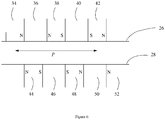
- Figure 6 shows a first possible arrangement of magnets on the surfaces 26, 28 of the first and second bearing surfaces. It will be apparent that the arrangements are the same, but are displaced from each other. In addition, it will be noted that the arrangements are shown here schematically as if the two surfaces are planar, rather than circular.
- the illustrated section of the surface 26 has a first magnet 34, made from permanent magnet material magnetized in a first direction, then a piece of iron 36, then a second magnet 38, made from permanent magnet material magnetized in a second direction opposite to the first direction, then a second piece of iron 40, then a third magnet 42, made from permanent magnet material magnetized in the first direction.
- the illustrated section of the surface 28 has a first magnet 44, made from permanent magnet material magnetized in the second direction, then a piece of iron 46, then a second magnet 48, made from permanent magnet material magnetized in the first direction, then a second piece of iron 50, then a third magnet 52, made from permanent magnet material magnetized in the second direction.
- the arrangement of magnets on the surfaces 26, 28 has a pitch P equal to the width of two of the magnets plus two of the pieces of iron, as shown in Figure 6 .
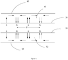
- Figure 7 shows a second possible arrangement of magnets on the surfaces 26, 28 of the first and second bearing surfaces. Again, it will be apparent that the arrangements are the same, but are displaced from each other, and it will be noted that the arrangements are shown here schematically as if the two surfaces are planar, rather than circular.
- the illustrated section of the surface 26 has a first magnet 54, made from permanent magnet material magnetized in a first direction, then a second magnet 56, made from permanent magnet material magnetized in a second direction opposite to the first direction, then a third magnet 58, made from permanent magnet material magnetized in the first direction, then a fourth magnet 60, made from permanent magnet material magnetized in the second direction, and so on.
- a piece of ferromagnetic material, for example iron, 62 is connected to one end of each of these magnets 54, 56, 58, 60.
- the illustrated section of the surface 28 has a first magnet 64, made from permanent magnet material magnetized in the second direction, then a second magnet 66, made from permanent magnet material magnetized in the first direction, then a third magnet 68, made from permanent magnet material magnetized in the second direction, then a fourth magnet 70, made from permanent magnet material magnetized in the first direction, and so on.
- a piece of ferromagnetic material, for example iron, 72 is connected to one end of each of these magnets 64, 66, 68, 70.
- the arrangement of magnets on the surfaces 26, 28 has a pitch P equal to the width of two of the magnets as shown in Figure 7 .
- Figure 8 shows a third possible arrangement of magnets on the surfaces 26, 28 of the first and second bearing surfaces. Again, it will be apparent that the arrangements are the same, but are displaced from each other, and it will be noted that the arrangements are shown here schematically as if the two surfaces are planar, rather than circular.
- the illustrated section of the surface 26 has permanent magnet material 82 magnetized in such a way as to produce a succession of North and South poles at the surface 26 as shown and very little magnetic field on the opposite surface 83, in an arrangement known as a Halbach array to a person skilled in the art.
- the illustrated section of surface 28 has permanent magnet material 92 magnetized in such a way as to produce a succession of magnetic North and South poles at the surface 28 as shown and very little magnetic field on the surface 93, again forming a Halbach array.
- the arrangement of magnets on the surfaces 26, 28 has a pitch P equal to the distance between two successive North poles, or between two successive South poles, as shown in Figure 8 .
- magnets are as shown in Figure 6 , or as shown in Figure 7 , or as shown in Figure 8 , they produce a degree of coupling between the surfaces 26 and 28. It is also possible to use an arrangement of magnets which is based on a mixture of the schemes outlined in Figures 6 , 7 and 8 . For instance a machine could be designed based on the magnets at surface 28 of Figure 8 co-operating with the magnets shown at surface 26 of Figure 7 .
- Figure 9 shows a first possible arrangement of ferromagnetic salient poles and magnets on the surfaces 26, 28 of the first and second bearing surfaces. It will be apparent that the arrangements are shown here schematically as if the two surfaces are planar, rather than circular.
- the illustrated section of the surface 26 has ferromagnetic salient poles 236, 240 as shown. Between the poles are non ferromagnetic slots 234, 238, 242.
- the illustrated section of the surface 28 has a first magnet 244, made from permanent magnet material magnetized in the second direction, then a piece of iron 246, then a second magnet 248, made from permanent magnet material magnetized in the first direction, then a second piece of iron 250, then a third magnet 252, made from permanent magnet material magnetized in the second direction.
- the arrangement of ferromagnetic salient poles and magnets on the surfaces 26, 28 has a pitch P equal to the width of two of the magnets plus two of the pieces of iron 246, as shown in Figure 9 .
- Figure 10 shows a second possible arrangement of ferromagnetic salient poles and magnets on the surfaces 26, 28 of the first and second bearing surfaces. Again, it will be apparent that the arrangements are shown here schematically as if the two surfaces are planar, rather than circular.
- the illustrated section of the surface 26 has ferromagnetic salient poles as shown at 254 and 258. Between the poles are non ferromagnetic slots 256 and 260.
- the illustrated section of the surface 28 has a first magnet 264, made from permanent magnet material magnetized in the second direction, then a second magnet 266, made from permanent magnet material magnetized in the first direction, then a third magnet 268, made from permanent magnet material magnetized in the second direction, then a fourth magnet 270, made from permanent magnet material magnetized in the first direction, and so on.
- a piece of ferromagnetic material, for example iron, 272 is connected to one end of each of these magnets 264, 266, 268, 270.
- the arrangement of ferromagnetic salient poles and magnets on the surfaces 26, 28 has a pitch P equal to the width of two of the magnets as shown in Figure 10 .
- Figure 11 shows a third possible arrangement of ferromagnetic salient poles and magnets on the surfaces 26, 28 of the first and second bearing surfaces. Again, it will be noted that the arrangements are shown here schematically as if the two surfaces are planar, rather than circular.
- the illustrated section of the surface 26 has ferromagnetic salient poles as shown at 282 and 284. Between the poles are non ferromagnetic slots 283 and 285.
- the illustrated section of surface 28 has permanent magnet material 292 magnetized in such a way as to produce a succession of magnetic North and South poles at the surface 28 as shown and very little magnetic field on the surface 293, forming a structure known to a person skilled in the art as a Halbach array.
- the arrangement of ferromagnetic salient poles and magnets on the surfaces 26, 28 has a pitch P equal to the distance between two successive North poles, or between two successive South poles, as shown in Figure 11 .
- ferromagnetic salient poles and magnets are as shown in Figure 9 , or as shown in Figure 10 , or as shown in Figure 11 , they produce a degree of coupling between the surfaces 26 and 28.
- magnétique field at surfaces 26 or 28 it is also possible to produce the magnetic field at surfaces 26 or 28 by using conventional electrical machine windings instead of magnets.
- the coupling with the ferromagnetic salient poles may be enhanced by using a conventional electrical machine winding round each ferromagnetic salient pole.
- Figure 12 shows in more detail the arrangements of the magnets or salient poles on the surfaces 26, 28. Specifically, the magnets or poles are arranged in cylindrical patterns. Axial displacements of the spinning support structure will result in a restoring force being produced by the magnetic arrangements on surfaces 26 and 28.
- the shape of the restoring force versus displacement depends on the exact detail of the design but is often approximately sinusoidal as shown in Figure 13 .
- the distance S as shown on Figure 13 depends on the exact detail of the design. However, in the case of the arrangements shown in Figure 6 , Figure 7 and Figure 8 , S is approximately equal to P /2, where P is labelled on Figure 6 , Figure 7 and Figure 8 , while, in the case of the arrangements shown in Figure 9 , Figure 10 and Figure 11 , S is approximately equal to P /4, where P is labelled on Figure 9 , Figure 10 and Figure 11 .
- the restoring force versus displacement characteristic illustrated in Figure 13 is advantageous as it is clear that surfaces 26 and 28 exhibit stable equilibrium with respect to displacement within the range labelled S on Figure 13 .
- the more common magnetic bearing system illustrated schematically in Figure 14 based on attractive magnetic forces, is less advantageous as a passive system.
- Figure 14 illustrates the principle used in a typical state of the art attractive force magnetic bearing.
- a ferromagnetic yoke 601 surrounds a winding 602 carrying electrical current such that magnetic force attracts the yoke 601 and a second ferromagnetic surface 603 towards each other.
- the force produced is generally normal to the surface 603, rather than in a tangential (shear) direction as in the systems illustrated in Figures 6 , 7 , 8 , 9 , 10 , 11 .
- the magnetic field is provided by constant electrical current in the winding 602 or by a system of permanent magnets.
- the normal force increases as the gap between 601 and 603 closes, so that there is no passive stable equilibrium condition.
- the current in the winding 602 is controlled so as to produce a varying normal force as required.
- Figure 15 is a schematic diagram showing how a repulsion force magnetic bearing system can be used to offset the axial force on rotor 18.
- the DSM system described in Figure 6 , Figure 7 and Figure 8 can also be used to provide a repulsion force magnetic bearing system.
- Figure 15 shows a cross section through the rotor 18.
- Shaft 501 is constrained to be stationary by a support structure not shown here.
- Stationary flanges 502 are joined to the shaft 501.
- the magnet support structure 503 rotates on the shaft 501 carried on bearings 505.
- the helical magnets (DSM) or helical salient poles, (MR), at surface 504 are arranged on the outside diameter of 503.
- Mounted on the flange 502 at position 601 and 602 are the magnetic thrust bearings, of which more below.
- the bearings 505, which may be any previously described bearings such as mechanical rolling element bearings, mechanical plain bearings, active magnetic bearings or fluid bearings are arranged so as to allow a small amount of movement in the axial direction of rotor 18, but so as to constrain the structure 503 within industrially acceptable tolerances in other directions.
- the space shown as 508 contains the internal electric motor or generator as previously described ( EP-A- 2335344 and PCT/GB20 12/053143 ).
- the axial force A18 acts on the support structure 503 as a result of electromagnetic interactions between the magnetic structure 504 and the corresponding magnetic arrangement on the toroid 10, as previously described in patent applications ( EP-A-2335344 and PCT/GB2012/053143 ).
- the magnetic bearings at positions 601 and 602 are arranged so that a magnetic repulsion force appears between the surfaces 26 and 28.
- the repulsion force between surfaces 26 and 28 becomes larger as the gap between surfaces 26 and 28 becomes smaller.
- the gaps between surfaces 26 and 28 in the bearings 601 and 602 will be substantially similar.
- the gap between surfaces 26 and 28 of bearing 601 or 602 closes and the repulsion force becomes greater, in opposition to the axial force A18 so that a passive stable equilibrium position can be attained.
- Some or all of the axial force A18 appears across the magnetic thrust bearings at positions such as 601 or 602, so as to reduce or remove substantially all of the axial force on the bearings 505.
- the magnetic thrust bearings shown at positions 601 and 602 comprise a first annular surface 26 attached to the spinning support structure 503 and a second annular surface 28 attached to the stationary part 502.
- Provided on surfaces 26 and 28 are arrangements of magnets configured so that 503 can rotate about 501 easily but can move in the axial direction of rotor 18 only within small limits determined by design.
- Figure 16 shows in more detail the arrangements of the magnets on the surfaces 26, 28 for a repulsive bearing system. Specifically, the magnets are arranged in annular patterns. Axial displacements of the spinning support structure will result in a restoring force being produced by the magnetic arrangements at positions 601 and 602.
Description
- This invention relates to reducing bearing forces in an electrical machine.
- Electrical machines in the form of generators are very well known, in which a primary source of energy is used to rotate a body, and this rotor cooperates with a stator to produce an electric current. However, where the primary source of energy is one of the common sources of renewable energy, such as wind, tide, or wave, the rotor typically moves rather slowly, at least compared with the 3000rpm achieved in a conventional power station.
- A recent patent application (
EP-A-2335344 ) describes machines which have an integrated magnetic gearing system which converts the slow rotation of a prime mover into faster rotation of a rotor in a generator. Double-sided arrays of magnets are employed to produce a very torque dense magnetic gearing system which results in a smaller machine. - However, in some cases a high torque density is not necessary. A later patent application (
PCT/GB2012/053143 - For convenience these previous machines are here referred to as Double Sided Magnet (DSM) or Magnet Reluctance (MR) machines respectively.
- In common with many other electrical machines, these new machines include spinning rotors and bearings are required to carry them. Conventional mechanical rolling or plain bearings, magnetic bearings or fluid bearings can be used. The bearing forces can be high in both of these previously described sets of machines.
- High bearing forces are disadvantageous to conventional bearings in many ways, for instance higher initial cost and mass, reduced length of service, higher noise and lower efficiency.
- In the case of active magnetic bearings, electrical power is supplied to coils which produce a magnetic field which is used to control the position of the spinning rotor. Larger bearing forces here give rise to more power, larger electromagnets and lower efficiency.
-
US2013/126669 discloses an electric drive device, in which it is mentioned that one or more bearings may be magnetic bearings. -
US-5,856,719 discloses a magnetic drive with a magnetic thrust bearing. -
US2013/033136 discloses a further magnetic drive with a magnetic thrust bearing. - According to one aspect of the invention, there is provided a magnetic drive, comprising:
- a prime mover, having a first magnet array on a first surface thereof;
a rotor, having a second magnet array on an outer surface thereof, the outer surface of the rotor being located adjacent to the first surface of the prime mover such that movement of the prime mover causes rotation of the rotor about an axis of rotation;
a support member, having a shaft for defining the axis of rotation of the rotor, and having a third magnet array, - wherein the third magnet array extends parallel to the axis of rotation of the rotor,
- wherein a fourth magnet array is provided on the rotor extending parallel to the axis of rotation of the rotor, and
- wherein the third magnet array cooperates with the fourth magnet array to form a magnetic bearing to resist forces on the rotor acting along the axis of rotation thereof.
- Thus, it is described how bearing forces in the DSM and MR machines may be reduced.
- For a better understanding of the present invention, and to show how it can be put into effect, reference will now be made, by way of example, to the accompanying drawings, in which:-
-
Figure 1 is a schematic diagram, illustrating a part of a machine in accordance with the previous inventions. -
Figure 2 is a schematic diagram, illustrating a part of a machine in accordance with the previous inventions, showing the main forces and torques. -
Figure 3 is a schematic diagram, illustrating how the radial bearing forces may be substantially reduced by an alternative arrangement of the first and second rotors. -
Figure 4 is a schematic diagram, illustrating how the radial bearing forces may be substantially reduced by a second alternative arrangement of the first and second rotors. -
Figures 5a and5b are cross-sectional views through a rotor of the machine shown inFigure 1 ,Figure 3 orFigure 4 . -
Figure 6 shows a first arrangement of magnets on the first and second bearing surfaces in the machine ofFigure 5 . -
Figure 7 shows a second alternative arrangement of magnets on the first and second bearing surfaces in the machine ofFigure 5 . -
Figure 8 shows a third alternative arrangement of magnets on the first and second bearing surfaces in the machine ofFigure 5 . -
Figure 9 shows a first arrangement of ferromagnetic salient poles and magnets on the first and second bearing surfaces in the machine ofFigure 5 . -
Figure 10 shows a second alternative arrangement of ferromagnetic salient poles and magnets on the first and second bearing surfaces in the machine ofFigure 5 . -
Figure 11 shows a third alternative arrangement of ferromagnetic salient poles and magnets on the first and second bearing surfaces in the machine ofFigure 5 . -
Figure 12 shows another aspect of the arrangement of magnets for the shear type bearing shown inFigure 5 . -
Figure 13 illustrates the variation of force with displacement in a bearing as illustrated. -
Figure 14 is a schematic diagram, illustrating a conventional attraction type of magnetic bearing. -
Figure 15 is an alternative cross-sectional view through the part shown inFigure 1 . -
Figure 16 shows another aspect of the repulsion type magnetic bearing shown inFigure 15 . -
Figure 1 shows the general structure of an electrical machine 8 in accordance with the previous two patent applications (EP-A- 2335344 andPCT/GB2012/053143 - The machine 8 of
Figure 1 has afirst rotor 10, which is connected to anaxle 12 by a support structure shown here in the form ofspokes 14. Rotation of theaxle 12 then causes therotor 10 to rotate about the axis defined by the axle. The rotation of theaxle 12 can be driven by a power source such as a wind turbine, a tidal current machine, or a wave energy converter, and although it can of course be driven by any power source, the machine of the present invention is particularly suitable for situations where the driving rotation is at a relatively low speed, for example at about 20rpm for the case of a typical 1.5MW wind turbine. In addition, althoughFigure 1 shows therotor 10 being driven through theaxle 12, it can be driven directly by a body that is being caused to rotate by the external power source. - The
rotor 10 is generally toroidal. That is, it has an annular shape, which can be generated by rotating a circle about an axis that lies in the plane of the circle but outside the circle. This axis is then the axis about which the rotor is caused to rotate. - However, the surface of the rotor is not a complete torus. Specifically, the part of the circular cross-section that lies furthest away from the axis of rotation is omitted, leaving an
annular gap 16. - Visible through the
gap 16 inFigure 1 is a cylindricalsecond rotor 18, which has an outer circular cross-section that is slightly smaller than the inner circular cross-section of therotor 10. - Although
Figure 1 shows only one cylindricalsecond rotor 18, many such second rotors can in fact be located within the first rotor. -
Figure 2 is a schematic view of both the DSM and MR machines. - As described in the previous DSM application (
EP-A- 2335344 ) helical arrangements of magnets on the facing surfaces of therotor 10 and thesecond rotor 18 can be provided such that a torque T10 applied torotor 10 will give rise to a resultant torque T18 onrotor 18 and vice versa. - In the previous MR application (
PCT/GB2012/053143 rotor 10 and thesecond rotor 18 can be provided such that a torque T10 applied torotor 10 will give rise to a resultant torque T18 onrotor 18 and vice versa. The magnets can be arranged on the surface ofrotor 10, while salient poles are provided on the surface ofrotor 18. Alternatively, the salient poles can be arranged on the surface ofrotor 10, while magnets are provided on the surface ofrotor 18. - In both the DSM and MR systems, as well as the desired torque being produced, there are also some undesirable forces present in the system. It is one purpose of the present invention to reduce the levels of the undesirable forces.
-
Figure 2 shows the radial force onrotor 18 labelled R18. This force acts mainly along a normal to the common surface ofrotors rotor 18 shown as R18. This force causes an undesirable radial load on bearings which supportrotor 18. If R18 is considered to be larger than convenient, it may be rendered negligible by exploiting cancellation of the radial forces when more than onetoroidal rotor 10 is used. Systems using two toroid sections have been described previously in (EP-A- 2335344 andPCT/GB2012/053143 Figure 3 andFigure 4 . - In the case of both the DSM and
MR machines 120 illustrated inFigure 3 , if therotor 126 is spaced an equal distance between the twotoroidal section rotors rotor 126 will be in substantially opposite directions and will substantially cancel. - In the case of both the DSM and
MR machines 130 illustrated inFigure 4 , if therotor 136 is spaced an optimal distance between the twotoroidal section rotors rotor 136 will be substantially in opposite directions and will substantially cancel. -
Figure 2 shows the axial force onrotor 18 labelled as A18. This force acts mainly along the axis of therotor 18. This undesirable force is directly related to the required torque T18, so cannot be cancelled out as in the case of R18. The axial force onrotor 18 can be calculated approximately as:
- Where revs18 and revs10 are the revolutions per minute of
rotor 18 androtor 10 respectively and R10 is the perpendicular distance between the axes ofrotors - As an example, using the DSM system to design a compact generator for a 10MW wind turbine, with a multiplicity of
rotors 18, typical values are as follows: - revs10 =10 rpm
- revs18 =3000 rpm
- T18 =1000 Nm
- R10 =2 m
- So A18 = 150kN or 15 tonnes
- It will be appreciated that the force A18 can easily be reduced, but only at the expense of a less compact generator.
- Conventionally, the force A18 would be carried by mechanical bearings, which could consist of combined thrust and axial force bearings, or by a set of bearings, some of which carry the radial forces and some of which carry the thrust forces, or by a mixture of several types of bearings.
- This invention concerns a system of magnets arranged so as to counteract some or all of the axial force A18. For the purpose of illustration only,
Figures 5a and5b each show a cross section through the rotor 18 (or therotor 126 in the embodiment ofFigure 3 or therotor 136 in the embodiment ofFigure 4 ). The invention however allows other similar arrangements.Shaft 501 provides the axis of rotation of therotor 18, and is constrained to be stationary by a support structure not shown here. Astationary flange 502 is joined toshaft 501 . - The
magnet support structure 503 rotates on theshaft 501 carried onbearings 505. The helical magnets (in the case of the DSM structure described above) or helical salient poles (in the case of the MR structure) are provided on thesurface 504, arranged on the outside diameter of therotating body 503. - Mounted on the
flange 502 are the magnetic thrust bearings, which are described in more detail below. Thebearings 505, which may be any previously described bearings such as mechanical rolling element bearings, mechanical plain bearings, active magnetic bearings or fluid bearings are arranged so as to allow a small amount of movement in the axial direction ofrotor 18, but so as to constrain thestructure 503 within industrially acceptable tolerances in other directions. The axial force A18 acts on thesupport structure 503 as a result of electromagnetic interactions between themagnetic structure 504 and the corresponding magnetic arrangement on thetoroid 10, as previously described in patent applications (EP-A- 2335344 andPCT/GB2012/053143 - The
space 508 defined by themagnet support structure 503 contains the internal electric motor or generator as previously described (EP-A- 2335344 andPCT/GB2012/053143 - Some or all of the axial force A18 appears across the magnetic thrust bearings.
-
Figure 5a shows an embodiment in which themagnetic thrust bearings 506 comprise a firstmagnetic surface 26 provided on a radially inwards facing surface of themagnet support structure 503 and a secondmagnetic surface 28 provided on a radially outwards facing surface of aprotrusion 502a from theflange 502. Themagnetic thrust bearings 506 inFigure 5a are therefore provided at a radially outer region of thespace 508. -
Figure 5b shows an embodiment in which themagnetic thrust bearings 507 comprise a firstmagnetic surface 26 provided on a radially inwards facing surface of aprotrusion 502b from theflange 502 and a secondmagnetic surface 28 provided on a radially outwards facing surface of themagnet support structure 503. Themagnetic thrust bearings 507 inFigure 5b are therefore provided at a radially inner region of thespace 508. - In other embodiments, magnetic thrust bearings can be provided at both of the positions shown in
Figures 5a and5b , and/or at one or more positions intermediate between those shown inFigures 5a and5b . - The effect of the magnetic thrust bearings is to reduce or remove substantially all of the axial force on the
bearings 505. - In many applications of either the DSM or MR system, the force A18 could be aligned along both possible directions and could be of an unknown magnitude. For instance in a wind turbine the direction and force of the wind varies. The magnitude of A18 will, however, under normal operating conditions, always lie between certain limits. These limits are determined by the maximum achievable shear force between the
magnetic structure 504 and the corresponding magnetic arrangement on thetoroid 10. This means that it is possible to calculate exactly how much thrust is required from themagnetic thrust bearings thrust bearings magnetic structure 504 and the corresponding magnetic arrangement on thetoroid 10, then thebearings rotor 10 without damage before any out of range displacement of bearing 506 or 507 can occur. - In the case of
bearings 506 positioned as shown inFigure 5a , the magnetic thrust bearing comprises aninner surface 26 attached to the spinningsupport structure 503 and anouter surface 28 attached to thestationary part 502. In the case of bearings 507positioned as shown inFigure 5b , the magnetic thrust bearing comprises aninner surface 26 attached to thestationary part 502 and anouter surface 28 attached to the spinningsupport structure 503. In either case, provided onsurfaces support structure 503 can rotate about thestationary axis 501 easily, but can move in the axial direction ofrotor 18 only within small limits determined by design. -
Figure 6 shows a first possible arrangement of magnets on thesurfaces surface 26 has afirst magnet 34, made from permanent magnet material magnetized in a first direction, then a piece of iron 36, then asecond magnet 38, made from permanent magnet material magnetized in a second direction opposite to the first direction, then a second piece ofiron 40, then athird magnet 42, made from permanent magnet material magnetized in the first direction. - The illustrated section of the
surface 28 has afirst magnet 44, made from permanent magnet material magnetized in the second direction, then a piece ofiron 46, then asecond magnet 48, made from permanent magnet material magnetized in the first direction, then a second piece ofiron 50, then athird magnet 52, made from permanent magnet material magnetized in the second direction. - In this case, the arrangement of magnets on the
surfaces Figure 6 . -
Figure 7 shows a second possible arrangement of magnets on thesurfaces - In
Figure 7 , the illustrated section of thesurface 26 has afirst magnet 54, made from permanent magnet material magnetized in a first direction, then asecond magnet 56, made from permanent magnet material magnetized in a second direction opposite to the first direction, then athird magnet 58, made from permanent magnet material magnetized in the first direction, then afourth magnet 60, made from permanent magnet material magnetized in the second direction, and so on. A piece of ferromagnetic material, for example iron, 62 is connected to one end of each of thesemagnets - The illustrated section of the
surface 28 has afirst magnet 64, made from permanent magnet material magnetized in the second direction, then asecond magnet 66, made from permanent magnet material magnetized in the first direction, then athird magnet 68, made from permanent magnet material magnetized in the second direction, then afourth magnet 70, made from permanent magnet material magnetized in the first direction, and so on. A piece of ferromagnetic material, for example iron, 72 is connected to one end of each of thesemagnets - In this case, the arrangement of magnets on the
surfaces Figure 7 . -
Figure 8 shows a third possible arrangement of magnets on thesurfaces - In
Figure 8 , the illustrated section of thesurface 26 haspermanent magnet material 82 magnetized in such a way as to produce a succession of North and South poles at thesurface 26 as shown and very little magnetic field on theopposite surface 83, in an arrangement known as a Halbach array to a person skilled in the art. - The illustrated section of
surface 28 haspermanent magnet material 92 magnetized in such a way as to produce a succession of magnetic North and South poles at thesurface 28 as shown and very little magnetic field on thesurface 93, again forming a Halbach array. - Again, the arrangement of magnets on the
surfaces Figure 8 . - Whether the magnets are as shown in
Figure 6 , or as shown inFigure 7 , or as shown inFigure 8 , they produce a degree of coupling between thesurfaces Figures 6 ,7 and8 . For instance a machine could be designed based on the magnets atsurface 28 ofFigure 8 co-operating with the magnets shown atsurface 26 ofFigure 7 . - It is also possible to produce the magnetic field at
surfaces - If conventional electrical machine windings are used, it is readily possible for a person skilled in the art to create an actively controlled bearing in which the forces between the parts are varied by varying the current in the windings as required.
-
Figure 9 shows a first possible arrangement of ferromagnetic salient poles and magnets on thesurfaces surface 26 has ferromagneticsalient poles ferromagnetic slots - The illustrated section of the
surface 28 has afirst magnet 244, made from permanent magnet material magnetized in the second direction, then a piece ofiron 246, then asecond magnet 248, made from permanent magnet material magnetized in the first direction, then a second piece ofiron 250, then athird magnet 252, made from permanent magnet material magnetized in the second direction. - In this case, the arrangement of ferromagnetic salient poles and magnets on the
surfaces iron 246, as shown inFigure 9 . -
Figure 10 shows a second possible arrangement of ferromagnetic salient poles and magnets on thesurfaces - In
Figure 10 , the illustrated section of thesurface 26 has ferromagnetic salient poles as shown at 254 and 258. Between the poles are nonferromagnetic slots surface 28 has afirst magnet 264, made from permanent magnet material magnetized in the second direction, then asecond magnet 266, made from permanent magnet material magnetized in the first direction, then athird magnet 268, made from permanent magnet material magnetized in the second direction, then afourth magnet 270, made from permanent magnet material magnetized in the first direction, and so on. A piece of ferromagnetic material, for example iron, 272 is connected to one end of each of thesemagnets - In this case, the arrangement of ferromagnetic salient poles and magnets on the
surfaces Figure 10 . -
Figure 11 shows a third possible arrangement of ferromagnetic salient poles and magnets on thesurfaces - In
Figure 11 , the illustrated section of thesurface 26 has ferromagnetic salient poles as shown at 282 and 284. Between the poles are nonferromagnetic slots - The illustrated section of
surface 28 haspermanent magnet material 292 magnetized in such a way as to produce a succession of magnetic North and South poles at thesurface 28 as shown and very little magnetic field on thesurface 293, forming a structure known to a person skilled in the art as a Halbach array. - Again, the arrangement of ferromagnetic salient poles and magnets on the
surfaces Figure 11 . - Whether the ferromagnetic salient poles and magnets are as shown in
Figure 9 , or as shown inFigure 10 , or as shown inFigure 11 , they produce a degree of coupling between thesurfaces - In any event, while there is described here an embodiment in which the ferromagnetic salient poles are on the
surface 26, while the magnets are on thesurface 28, the opposite arrangement would also be possible, with the ferromagnetic salient poles on thesurface 28 and the magnets on thesurface 26. - It is also possible to produce the magnetic field at
surfaces - If conventional electrical machine windings are used, it is readily possible for a person skilled in the art to create an actively controlled bearing in which the forces between the parts are varied by varying the current in the windings as required.
-
Figure 12 shows in more detail the arrangements of the magnets or salient poles on thesurfaces surfaces - The shape of the restoring force versus displacement depends on the exact detail of the design but is often approximately sinusoidal as shown in
Figure 13 . - The distance S as shown on
Figure 13 depends on the exact detail of the design. However, in the case of the arrangements shown inFigure 6 ,Figure 7 andFigure 8 , S is approximately equal to P/2, where P is labelled onFigure 6 ,Figure 7 andFigure 8 , while, in the case of the arrangements shown inFigure 9 ,Figure 10 andFigure 11 , S is approximately equal to P/4, where P is labelled onFigure 9 ,Figure 10 andFigure 11 . - The restoring force versus displacement characteristic illustrated in
Figure 13 is advantageous as it is clear that surfaces 26 and 28 exhibit stable equilibrium with respect to displacement within the range labelled S onFigure 13 . This means that a passive system is easily realised, although of course more expensive active magnetic bearings based on the shear force principles described here can readily be devised by one skilled in the art. The more common magnetic bearing system illustrated schematically inFigure 14 , based on attractive magnetic forces, is less advantageous as a passive system. -
Figure 14 illustrates the principle used in a typical state of the art attractive force magnetic bearing. Aferromagnetic yoke 601 surrounds a winding 602 carrying electrical current such that magnetic force attracts theyoke 601 and a secondferromagnetic surface 603 towards each other. The force produced is generally normal to thesurface 603, rather than in a tangential (shear) direction as in the systems illustrated inFigures 6 ,7 ,8 ,9 ,10 ,11 . In a passive system the magnetic field is provided by constant electrical current in the winding 602 or by a system of permanent magnets. The normal force increases as the gap between 601 and 603 closes, so that there is no passive stable equilibrium condition. In an active bearing system the current in the winding 602 is controlled so as to produce a varying normal force as required. -
Figure 15 is a schematic diagram showing how a repulsion force magnetic bearing system can be used to offset the axial force onrotor 18. - The DSM system described in
Figure 6 ,Figure 7 andFigure 8 can also be used to provide a repulsion force magnetic bearing system. - For the purpose of illustration only,
Figure 15 shows a cross section through therotor 18. The invention however allows other similar arrangements.Shaft 501 is constrained to be stationary by a support structure not shown here.Stationary flanges 502 are joined to theshaft 501. Themagnet support structure 503 rotates on theshaft 501 carried onbearings 505. The helical magnets (DSM) or helical salient poles, (MR), atsurface 504 are arranged on the outside diameter of 503. Mounted on theflange 502 atposition bearings 505, which may be any previously described bearings such as mechanical rolling element bearings, mechanical plain bearings, active magnetic bearings or fluid bearings are arranged so as to allow a small amount of movement in the axial direction ofrotor 18, but so as to constrain thestructure 503 within industrially acceptable tolerances in other directions. The space shown as 508 contains the internal electric motor or generator as previously described (EP-A- 2335344 andPCT/ GB20 12/053143 - The axial force A18 acts on the
support structure 503 as a result of electromagnetic interactions between themagnetic structure 504 and the corresponding magnetic arrangement on thetoroid 10, as previously described in patent applications (EP-A-2335344 andPCT/GB2012/053143 positions surfaces - The repulsion force between
surfaces surfaces surfaces bearings surfaces bearings 505. - The magnetic thrust bearings shown at
positions annular surface 26 attached to the spinningsupport structure 503 and a secondannular surface 28 attached to thestationary part 502. Provided onsurfaces rotor 18 only within small limits determined by design. - The arrangements of magnets on
surfaces Figure 6 ,Figure 7 andFigure 8 . In order to obtain a magnet system which produces repulsion betweensurfaces surfaces Figure 7 andFigure 8 illustrate the position for maximum repulsion. OnFigure 6 ,Figure 7 andFigure 8 it will be noted that the arrangements are shown here schematically as if the two surfaces are planar, rather than circular. - It is also possible to produce the magnetic field at
surfaces - If conventional electrical machine windings are used, it is readily possible for a person skilled in the art to create an actively controlled bearing in which the forces between the parts are varied by varying the current in the windings as required.
-
Figure 16 shows in more detail the arrangements of the magnets on thesurfaces positions - There is thus described a magnetic drive system in which a magnetic bearing is provided to reduce axial forces acting on the components.
Claims (14)
- A magnetic drive, comprising:a prime mover (10), having a first surface;a rotor (18, 126, 136), having an outer surface (504),the first surface of the prime mover and the outer surface of the rotor being provided with a helical first magnet array and a helical second magnet array, or with a helical first magnet array and a helical first array of ferromagnetic salient poles, andthe outer surface of the rotor being located adjacent to the first surface of the prime mover such that movement of the prime mover causes rotation of the rotor about an axis of rotation;a support member, having a stationary shaft (501) for defining the axis of rotation of the rotor, and having a stationary flange joined to the shaft, wherein the rotor rotates on the shaft;characterised in that the rotor and the stationary flange are provided with a third magnet array (28) and a fourth magnet array (26), both extending parallel to the axis of rotation of the rotor, or with a third magnet array and a second array of ferromagnetic salient poles, both extending parallel to the axis of rotation of the rotor, and in that the third magnet array (28) cooperates with the fourth magnet array (26) or with the second array of ferromagnetic salient poles to form a magnetic thrust bearing (506) to resist forces on the rotor acting along the axis of rotation thereof.
- A magnetic drive as claimed in claim 1, wherein the rotor is a rotor of an electrical machine, further comprising a stator of the electrical machine.
- A magnetic drive as claimed in claim 2, wherein the electrical machine is a motor.
- A magnetic drive as claimed in claim 2, wherein the electrical machine is a generator.
- A magnetic drive as claimed in claim 2, 3 or 4, wherein the stator is mounted inside the rotor.
- A magnetic drive as claimed in any preceding claim, wherein the rotor is supported on the shaft by bearings (505) in addition to the magnetic bearing.
- A magnetic drive as claimed in claim 6, wherein the additional bearings comprise mechanical bearings.
- A magnetic drive as claimed in claim 6, wherein the additional bearings comprise fluid bearings.
- A magnetic drive as claimed in claim 6, wherein the additional bearings comprise active magnetic bearings.
- A magnetic drive as claimed in any preceding claim, wherein the third magnet array cooperates with the fourth magnet array on the rotor to form a passive magnetic bearing.
- A magnetic drive as claimed in one of claims 1 to 9, wherein the third magnet array cooperates with the fourth magnet array on the rotor to form an active magnetic bearing.
- A magnetic drive as claimed in any preceding claim, wherein the fourth magnet array is arranged on an internal surface of the rotor.
- A magnetic drive as claimed in claim 12, wherein the fourth magnet array is arranged on a radially outward internal surface of the rotor.
- A magnetic drive as claimed in claim 12, wherein the fourth magnet array is arranged on a radially inward internal surface of the rotor.
Applications Claiming Priority (2)
| Application Number | Priority Date | Filing Date | Title |
|---|---|---|---|
| GB1311852.6A GB2515766A (en) | 2013-07-02 | 2013-07-02 | Reducing bearing forces in an electrical machine |
| PCT/GB2014/051993 WO2015001331A2 (en) | 2013-07-02 | 2014-07-01 | Reducing bearing forces in an electrical machine |
Publications (2)
| Publication Number | Publication Date |
|---|---|
| EP3017529A2 EP3017529A2 (en) | 2016-05-11 |
| EP3017529B1 true EP3017529B1 (en) | 2018-09-05 |
Family
ID=48999391
Family Applications (1)
| Application Number | Title | Priority Date | Filing Date |
|---|---|---|---|
| EP14736928.4A Active EP3017529B1 (en) | 2013-07-02 | 2014-07-01 | Reducing bearing forces in an electrical machine |
Country Status (8)
| Country | Link |
|---|---|
| US (1) | US10778063B2 (en) |
| EP (1) | EP3017529B1 (en) |
| JP (1) | JP2016524448A (en) |
| CN (1) | CN105408649B (en) |
| DK (1) | DK3017529T3 (en) |
| ES (1) | ES2701052T3 (en) |
| GB (1) | GB2515766A (en) |
| WO (1) | WO2015001331A2 (en) |
Families Citing this family (4)
| Publication number | Priority date | Publication date | Assignee | Title |
|---|---|---|---|---|
| US11124216B1 (en) * | 2016-07-15 | 2021-09-21 | Michael Wein | Multi-functional stroller |
| DE102017220437B8 (en) | 2017-11-16 | 2019-06-19 | Eagleburgmann Germany Gmbh & Co. Kg | Pump arrangement, in particular for supplying a mechanical seal assembly |
| CN108599526B (en) * | 2018-05-30 | 2020-03-31 | 宁波诺丁汉大学 | Connecting/disconnecting device |
| WO2023064948A1 (en) * | 2021-10-17 | 2023-04-20 | Iyer Narayan R | Magnetic peak load aversion in a wave energy conversion system |
Family Cites Families (23)
| Publication number | Priority date | Publication date | Assignee | Title |
|---|---|---|---|---|
| JPH0681963B2 (en) * | 1987-06-26 | 1994-10-19 | 株式会社三協精機製作所 | Rotating device |
| DE4223814A1 (en) * | 1992-07-20 | 1994-01-27 | Gerd Schuesler | Magnetic worm drive for contactless torque transmission for two shafts at right angles - spaced from each other so that magnetised worm and worm wheel face each other with variable polarity at periphery |
| JPH06235420A (en) | 1993-02-05 | 1994-08-23 | Koyo Seiko Co Ltd | Spindle motor |
| US5634390A (en) * | 1994-11-19 | 1997-06-03 | Ckd Corporation | Rotary actuator |
| EP0865680A1 (en) | 1994-12-12 | 1998-09-23 | Jorge De Armas | Electromagnetic-coupled/levitated apparatus and method for rotating equipment |
| JP3577558B2 (en) * | 1994-12-28 | 2004-10-13 | 光洋精工株式会社 | Flywheel equipment |
| JPH09303395A (en) * | 1996-05-07 | 1997-11-25 | Nippon Seiko Kk | Magnetic bearing device |
| US5928131A (en) * | 1997-11-26 | 1999-07-27 | Vascor, Inc. | Magnetically suspended fluid pump and control system |
| JP2000314421A (en) * | 1999-04-30 | 2000-11-14 | Sumitomo Electric Ind Ltd | Radial/axial combined bearing structure and spindle motor having the same |
| JP3773709B2 (en) * | 1999-08-06 | 2006-05-10 | 株式会社リコー | High-speed rotating body balance correction method |
| JP2002122137A (en) * | 2000-10-10 | 2002-04-26 | Sankyo Seiki Mfg Co Ltd | Bearing device |
| JP2002130256A (en) | 2000-10-18 | 2002-05-09 | Matsushita Electric Ind Co Ltd | Air dynamic bearing unit |
| US6861778B2 (en) * | 2003-02-28 | 2005-03-01 | Valentin M. Izraelev | System for passive and stable suspension of a rotor in rotor/stator assemblies |
| JP2006129664A (en) * | 2004-11-01 | 2006-05-18 | Maruyasu Kikai Kk | Driving device |
| CN101409478B (en) | 2007-10-10 | 2012-05-23 | 沈阳中北昊通电子科技有限公司 | Permanent magnetism levitation energy-storing flywheel system |
| US20100231076A1 (en) * | 2008-01-24 | 2010-09-16 | Akira Chiba | Bearingless motor |
| GB2463102A (en) * | 2008-09-05 | 2010-03-10 | David Rodger | Permanent magnet couplings |
| EP2413483A1 (en) * | 2010-07-30 | 2012-02-01 | Siemens Aktiengesellschaft | Electric drive device for an aircraft |
| US9203279B2 (en) * | 2011-08-03 | 2015-12-01 | Vycon, Inc. | Electric machine with inner magnet hub |
| EP2589827A1 (en) * | 2011-11-04 | 2013-05-08 | ETH Zürich | Rotating electrical machine and method for measuring a displacement of a rotating electrical machine |
| GB2497591A (en) * | 2011-12-16 | 2013-06-19 | David Rodger | Electrical machine |
| FR3002378B1 (en) * | 2013-02-20 | 2016-06-10 | Manutrans | MOBILE PIECE MAGNETS FOR SYNCHRONOUS MACHINE WITH PERMANENT MAGNETS. |
| CN106795913A (en) * | 2014-09-01 | 2017-05-31 | 大金工业株式会社 | Magnetic bearing |
-
2013
- 2013-07-02 GB GB1311852.6A patent/GB2515766A/en not_active Withdrawn
-
2014
- 2014-07-01 DK DK14736928.4T patent/DK3017529T3/en active
- 2014-07-01 WO PCT/GB2014/051993 patent/WO2015001331A2/en active Application Filing
- 2014-07-01 EP EP14736928.4A patent/EP3017529B1/en active Active
- 2014-07-01 US US14/901,480 patent/US10778063B2/en active Active
- 2014-07-01 JP JP2016522873A patent/JP2016524448A/en active Pending
- 2014-07-01 ES ES14736928T patent/ES2701052T3/en active Active
- 2014-07-01 CN CN201480037891.6A patent/CN105408649B/en active Active
Also Published As
| Publication number | Publication date |
|---|---|
| GB201311852D0 (en) | 2013-08-14 |
| WO2015001331A2 (en) | 2015-01-08 |
| ES2701052T3 (en) | 2019-02-20 |
| US10778063B2 (en) | 2020-09-15 |
| EP3017529A2 (en) | 2016-05-11 |
| JP2016524448A (en) | 2016-08-12 |
| CN105408649A (en) | 2016-03-16 |
| DK3017529T3 (en) | 2019-01-07 |
| WO2015001331A3 (en) | 2015-09-11 |
| CN105408649B (en) | 2018-11-06 |
| GB2515766A (en) | 2015-01-07 |
| US20160164371A1 (en) | 2016-06-09 |
Similar Documents
| Publication | Publication Date | Title |
|---|---|---|
| US9537362B2 (en) | Electrical machine with improved stator flux pattern across a rotor for providing high torque density | |
| US7960887B2 (en) | Permanent-magnet switched-flux machine | |
| WO2009129708A1 (en) | Direct driving combined type permanent magnet motor | |
| US10476349B2 (en) | Method and apparatus for compact axial flux magnetically geared machines | |
| EP3017529B1 (en) | Reducing bearing forces in an electrical machine | |
| US9641059B2 (en) | Flux focusing magnetic gear assembly using ferrite magnets or the like | |
| US9559577B2 (en) | Flux focusing magnetic gear assembly using ferrite magnets or the like | |
| KR101872262B1 (en) | Magnet generator | |
| CN110299815B (en) | Coaxial dual-rotor variable-speed electromagnetic driver | |
| JP4189250B2 (en) | Windmill | |
| JPWO2017158710A1 (en) | Flywheel device and rotating electric machine | |
| JP2007110776A (en) | Rotating-electric machine | |
| JP6572421B2 (en) | Axial type magnetic geared electric | |
| EP3087662A2 (en) | Shaftless generator | |
| EP4104278B1 (en) | An electromechanical device | |
| KR102497538B1 (en) | Motor | |
| US20230412057A1 (en) | Axial flux motor structure using magnetic levitation force and rotational force | |
| JPWO2011036723A1 (en) | Synchronous generator | |
| KR101838014B1 (en) | High Speed Motor | |
| KR20150145156A (en) | motor and the generator using the same | |
| CN117480713A (en) | Axial alignment system for a rotor of a rotating electrical machine and corresponding rotating electrical machine | |
| CN111602327A (en) | Rotating electrical machine | |
| JP2018078801A (en) | Rotary electric machine |
Legal Events
| Date | Code | Title | Description |
|---|---|---|---|
| PUAI | Public reference made under article 153(3) epc to a published international application that has entered the european phase |
Free format text: ORIGINAL CODE: 0009012 |
|
| 17P | Request for examination filed |
Effective date: 20160121 |
|
| AK | Designated contracting states |
Kind code of ref document: A2 Designated state(s): AL AT BE BG CH CY CZ DE DK EE ES FI FR GB GR HR HU IE IS IT LI LT LU LV MC MK MT NL NO PL PT RO RS SE SI SK SM TR |
|
| AX | Request for extension of the european patent |
Extension state: BA ME |
|
| DAX | Request for extension of the european patent (deleted) | ||
| STAA | Information on the status of an ep patent application or granted ep patent |
Free format text: STATUS: EXAMINATION IS IN PROGRESS |
|
| 17Q | First examination report despatched |
Effective date: 20170307 |
|
| REG | Reference to a national code |
Ref country code: DE Ref legal event code: R079 Ref document number: 602014031771 Country of ref document: DE Free format text: PREVIOUS MAIN CLASS: H02K0007090000 Ipc: H02K0049100000 |
|
| GRAP | Despatch of communication of intention to grant a patent |
Free format text: ORIGINAL CODE: EPIDOSNIGR1 |
|
| STAA | Information on the status of an ep patent application or granted ep patent |
Free format text: STATUS: GRANT OF PATENT IS INTENDED |
|
| RIC1 | Information provided on ipc code assigned before grant |
Ipc: F16C 39/06 20060101ALI20180118BHEP Ipc: F16C 32/04 20060101ALN20180118BHEP Ipc: H02K 7/09 20060101ALI20180118BHEP Ipc: H02K 49/10 20060101AFI20180118BHEP |
|
| INTG | Intention to grant announced |
Effective date: 20180213 |
|
| GRAS | Grant fee paid |
Free format text: ORIGINAL CODE: EPIDOSNIGR3 |
|
| GRAA | (expected) grant |
Free format text: ORIGINAL CODE: 0009210 |
|
| STAA | Information on the status of an ep patent application or granted ep patent |
Free format text: STATUS: THE PATENT HAS BEEN GRANTED |
|
| AK | Designated contracting states |
Kind code of ref document: B1 Designated state(s): AL AT BE BG CH CY CZ DE DK EE ES FI FR GB GR HR HU IE IS IT LI LT LU LV MC MK MT NL NO PL PT RO RS SE SI SK SM TR |
|
| REG | Reference to a national code |
Ref country code: GB Ref legal event code: FG4D |
|
| REG | Reference to a national code |
Ref country code: CH Ref legal event code: EP |
|
| REG | Reference to a national code |
Ref country code: AT Ref legal event code: REF Ref document number: 1038995 Country of ref document: AT Kind code of ref document: T Effective date: 20180915 |
|
| REG | Reference to a national code |
Ref country code: IE Ref legal event code: FG4D |
|
| REG | Reference to a national code |
Ref country code: DE Ref legal event code: R096 Ref document number: 602014031771 Country of ref document: DE |
|
| REG | Reference to a national code |
Ref country code: NL Ref legal event code: FP |
|
| REG | Reference to a national code |
Ref country code: DK Ref legal event code: T3 Effective date: 20190103 |
|
| REG | Reference to a national code |
Ref country code: SE Ref legal event code: TRGR |
|
| REG | Reference to a national code |
Ref country code: LT Ref legal event code: MG4D |
|
| PG25 | Lapsed in a contracting state [announced via postgrant information from national office to epo] |
Ref country code: RS Free format text: LAPSE BECAUSE OF FAILURE TO SUBMIT A TRANSLATION OF THE DESCRIPTION OR TO PAY THE FEE WITHIN THE PRESCRIBED TIME-LIMIT Effective date: 20180905 Ref country code: LT Free format text: LAPSE BECAUSE OF FAILURE TO SUBMIT A TRANSLATION OF THE DESCRIPTION OR TO PAY THE FEE WITHIN THE PRESCRIBED TIME-LIMIT Effective date: 20180905 Ref country code: BG Free format text: LAPSE BECAUSE OF FAILURE TO SUBMIT A TRANSLATION OF THE DESCRIPTION OR TO PAY THE FEE WITHIN THE PRESCRIBED TIME-LIMIT Effective date: 20181205 Ref country code: GR Free format text: LAPSE BECAUSE OF FAILURE TO SUBMIT A TRANSLATION OF THE DESCRIPTION OR TO PAY THE FEE WITHIN THE PRESCRIBED TIME-LIMIT Effective date: 20181206 |
|
| REG | Reference to a national code |
Ref country code: NO Ref legal event code: T2 Effective date: 20180905 |
|
| REG | Reference to a national code |
Ref country code: AT Ref legal event code: MK05 Ref document number: 1038995 Country of ref document: AT Kind code of ref document: T Effective date: 20180905 |
|
| REG | Reference to a national code |
Ref country code: ES Ref legal event code: FG2A Ref document number: 2701052 Country of ref document: ES Kind code of ref document: T3 Effective date: 20190220 |
|
| PG25 | Lapsed in a contracting state [announced via postgrant information from national office to epo] |
Ref country code: HR Free format text: LAPSE BECAUSE OF FAILURE TO SUBMIT A TRANSLATION OF THE DESCRIPTION OR TO PAY THE FEE WITHIN THE PRESCRIBED TIME-LIMIT Effective date: 20180905 Ref country code: LV Free format text: LAPSE BECAUSE OF FAILURE TO SUBMIT A TRANSLATION OF THE DESCRIPTION OR TO PAY THE FEE WITHIN THE PRESCRIBED TIME-LIMIT Effective date: 20180905 Ref country code: AL Free format text: LAPSE BECAUSE OF FAILURE TO SUBMIT A TRANSLATION OF THE DESCRIPTION OR TO PAY THE FEE WITHIN THE PRESCRIBED TIME-LIMIT Effective date: 20180905 |
|
| PG25 | Lapsed in a contracting state [announced via postgrant information from national office to epo] |
Ref country code: RO Free format text: LAPSE BECAUSE OF FAILURE TO SUBMIT A TRANSLATION OF THE DESCRIPTION OR TO PAY THE FEE WITHIN THE PRESCRIBED TIME-LIMIT Effective date: 20180905 Ref country code: CZ Free format text: LAPSE BECAUSE OF FAILURE TO SUBMIT A TRANSLATION OF THE DESCRIPTION OR TO PAY THE FEE WITHIN THE PRESCRIBED TIME-LIMIT Effective date: 20180905 Ref country code: AT Free format text: LAPSE BECAUSE OF FAILURE TO SUBMIT A TRANSLATION OF THE DESCRIPTION OR TO PAY THE FEE WITHIN THE PRESCRIBED TIME-LIMIT Effective date: 20180905 Ref country code: EE Free format text: LAPSE BECAUSE OF FAILURE TO SUBMIT A TRANSLATION OF THE DESCRIPTION OR TO PAY THE FEE WITHIN THE PRESCRIBED TIME-LIMIT Effective date: 20180905 Ref country code: PL Free format text: LAPSE BECAUSE OF FAILURE TO SUBMIT A TRANSLATION OF THE DESCRIPTION OR TO PAY THE FEE WITHIN THE PRESCRIBED TIME-LIMIT Effective date: 20180905 Ref country code: IS Free format text: LAPSE BECAUSE OF FAILURE TO SUBMIT A TRANSLATION OF THE DESCRIPTION OR TO PAY THE FEE WITHIN THE PRESCRIBED TIME-LIMIT Effective date: 20190105 |
|
| PG25 | Lapsed in a contracting state [announced via postgrant information from national office to epo] |
Ref country code: PT Free format text: LAPSE BECAUSE OF FAILURE TO SUBMIT A TRANSLATION OF THE DESCRIPTION OR TO PAY THE FEE WITHIN THE PRESCRIBED TIME-LIMIT Effective date: 20190105 Ref country code: SK Free format text: LAPSE BECAUSE OF FAILURE TO SUBMIT A TRANSLATION OF THE DESCRIPTION OR TO PAY THE FEE WITHIN THE PRESCRIBED TIME-LIMIT Effective date: 20180905 Ref country code: SM Free format text: LAPSE BECAUSE OF FAILURE TO SUBMIT A TRANSLATION OF THE DESCRIPTION OR TO PAY THE FEE WITHIN THE PRESCRIBED TIME-LIMIT Effective date: 20180905 |
|
| REG | Reference to a national code |
Ref country code: DE Ref legal event code: R097 Ref document number: 602014031771 Country of ref document: DE |
|
| PLBE | No opposition filed within time limit |
Free format text: ORIGINAL CODE: 0009261 |
|
| STAA | Information on the status of an ep patent application or granted ep patent |
Free format text: STATUS: NO OPPOSITION FILED WITHIN TIME LIMIT |
|
| 26N | No opposition filed |
Effective date: 20190606 |
|
| PG25 | Lapsed in a contracting state [announced via postgrant information from national office to epo] |
Ref country code: SI Free format text: LAPSE BECAUSE OF FAILURE TO SUBMIT A TRANSLATION OF THE DESCRIPTION OR TO PAY THE FEE WITHIN THE PRESCRIBED TIME-LIMIT Effective date: 20180905 |
|
| PG25 | Lapsed in a contracting state [announced via postgrant information from national office to epo] |
Ref country code: MC Free format text: LAPSE BECAUSE OF FAILURE TO SUBMIT A TRANSLATION OF THE DESCRIPTION OR TO PAY THE FEE WITHIN THE PRESCRIBED TIME-LIMIT Effective date: 20180905 |
|
| REG | Reference to a national code |
Ref country code: CH Ref legal event code: PL |
|
| PG25 | Lapsed in a contracting state [announced via postgrant information from national office to epo] |
Ref country code: TR Free format text: LAPSE BECAUSE OF FAILURE TO SUBMIT A TRANSLATION OF THE DESCRIPTION OR TO PAY THE FEE WITHIN THE PRESCRIBED TIME-LIMIT Effective date: 20180905 |
|
| REG | Reference to a national code |
Ref country code: BE Ref legal event code: MM Effective date: 20190731 |
|
| PG25 | Lapsed in a contracting state [announced via postgrant information from national office to epo] |
Ref country code: LU Free format text: LAPSE BECAUSE OF NON-PAYMENT OF DUE FEES Effective date: 20190701 Ref country code: CH Free format text: LAPSE BECAUSE OF NON-PAYMENT OF DUE FEES Effective date: 20190731 Ref country code: BE Free format text: LAPSE BECAUSE OF NON-PAYMENT OF DUE FEES Effective date: 20190731 Ref country code: LI Free format text: LAPSE BECAUSE OF NON-PAYMENT OF DUE FEES Effective date: 20190731 |
|
| REG | Reference to a national code |
Ref country code: DE Ref legal event code: R082 Ref document number: 602014031771 Country of ref document: DE Representative=s name: HL KEMPNER PATENTANWAELTE, SOLICITORS (ENGLAND, DE Ref country code: DE Ref legal event code: R082 Ref document number: 602014031771 Country of ref document: DE Representative=s name: HL KEMPNER PATENTANWALT, RECHTSANWALT, SOLICIT, DE |
|
| PG25 | Lapsed in a contracting state [announced via postgrant information from national office to epo] |
Ref country code: CY Free format text: LAPSE BECAUSE OF FAILURE TO SUBMIT A TRANSLATION OF THE DESCRIPTION OR TO PAY THE FEE WITHIN THE PRESCRIBED TIME-LIMIT Effective date: 20180905 |
|
| PG25 | Lapsed in a contracting state [announced via postgrant information from national office to epo] |
Ref country code: MT Free format text: LAPSE BECAUSE OF FAILURE TO SUBMIT A TRANSLATION OF THE DESCRIPTION OR TO PAY THE FEE WITHIN THE PRESCRIBED TIME-LIMIT Effective date: 20180905 Ref country code: HU Free format text: LAPSE BECAUSE OF FAILURE TO SUBMIT A TRANSLATION OF THE DESCRIPTION OR TO PAY THE FEE WITHIN THE PRESCRIBED TIME-LIMIT; INVALID AB INITIO Effective date: 20140701 |
|
| PG25 | Lapsed in a contracting state [announced via postgrant information from national office to epo] |
Ref country code: MK Free format text: LAPSE BECAUSE OF FAILURE TO SUBMIT A TRANSLATION OF THE DESCRIPTION OR TO PAY THE FEE WITHIN THE PRESCRIBED TIME-LIMIT Effective date: 20180905 |
|
| REG | Reference to a national code |
Ref country code: FR Ref legal event code: PLFP Year of fee payment: 9 |
|
| P01 | Opt-out of the competence of the unified patent court (upc) registered |
Effective date: 20230524 |
|
| PGFP | Annual fee paid to national office [announced via postgrant information from national office to epo] |
Ref country code: NL Payment date: 20230724 Year of fee payment: 10 |
|
| PGFP | Annual fee paid to national office [announced via postgrant information from national office to epo] |
Ref country code: NO Payment date: 20230705 Year of fee payment: 10 Ref country code: IT Payment date: 20230717 Year of fee payment: 10 Ref country code: IE Payment date: 20230705 Year of fee payment: 10 Ref country code: GB Payment date: 20230725 Year of fee payment: 10 Ref country code: FI Payment date: 20230705 Year of fee payment: 10 Ref country code: ES Payment date: 20230807 Year of fee payment: 10 |
|
| PGFP | Annual fee paid to national office [announced via postgrant information from national office to epo] |
Ref country code: SE Payment date: 20230724 Year of fee payment: 10 Ref country code: FR Payment date: 20230710 Year of fee payment: 10 Ref country code: DK Payment date: 20230725 Year of fee payment: 10 Ref country code: DE Payment date: 20230724 Year of fee payment: 10 |