EP3016883B1 - A package as well as a slide and a housing suitable for such a package - Google Patents
A package as well as a slide and a housing suitable for such a package Download PDFInfo
- Publication number
- EP3016883B1 EP3016883B1 EP14736717.1A EP14736717A EP3016883B1 EP 3016883 B1 EP3016883 B1 EP 3016883B1 EP 14736717 A EP14736717 A EP 14736717A EP 3016883 B1 EP3016883 B1 EP 3016883B1
- Authority
- EP
- European Patent Office
- Prior art keywords
- housing
- package
- slide
- hook
- recess
- Prior art date
- Legal status (The legal status is an assumption and is not a legal conclusion. Google has not performed a legal analysis and makes no representation as to the accuracy of the status listed.)
- Active
Links
Images





Classifications
-
- B—PERFORMING OPERATIONS; TRANSPORTING
- B65—CONVEYING; PACKING; STORING; HANDLING THIN OR FILAMENTARY MATERIAL
- B65D—CONTAINERS FOR STORAGE OR TRANSPORT OF ARTICLES OR MATERIALS, e.g. BAGS, BARRELS, BOTTLES, BOXES, CANS, CARTONS, CRATES, DRUMS, JARS, TANKS, HOPPERS, FORWARDING CONTAINERS; ACCESSORIES, CLOSURES, OR FITTINGS THEREFOR; PACKAGING ELEMENTS; PACKAGES
- B65D5/00—Rigid or semi-rigid containers of polygonal cross-section, e.g. boxes, cartons or trays, formed by folding or erecting one or more blanks made of paper
- B65D5/38—Drawer-and-shell type containers
-
- B—PERFORMING OPERATIONS; TRANSPORTING
- B65—CONVEYING; PACKING; STORING; HANDLING THIN OR FILAMENTARY MATERIAL
- B65D—CONTAINERS FOR STORAGE OR TRANSPORT OF ARTICLES OR MATERIALS, e.g. BAGS, BARRELS, BOTTLES, BOXES, CANS, CARTONS, CRATES, DRUMS, JARS, TANKS, HOPPERS, FORWARDING CONTAINERS; ACCESSORIES, CLOSURES, OR FITTINGS THEREFOR; PACKAGING ELEMENTS; PACKAGES
- B65D77/00—Packages formed by enclosing articles or materials in preformed containers, e.g. boxes, cartons, sacks or bags
- B65D77/04—Articles or materials enclosed in two or more containers disposed one within another
- B65D77/0413—Articles or materials enclosed in two or more containers disposed one within another the inner and outer containers being rigid or semi-rigid and the outer container being of polygonal cross-section formed by folding or erecting one or more blanks, e.g. carton
- B65D77/0433—Articles or materials enclosed in two or more containers disposed one within another the inner and outer containers being rigid or semi-rigid and the outer container being of polygonal cross-section formed by folding or erecting one or more blanks, e.g. carton the inner container being a tray or like shallow container, not formed by folding or erecting one or more blanks
-
- B—PERFORMING OPERATIONS; TRANSPORTING
- B65—CONVEYING; PACKING; STORING; HANDLING THIN OR FILAMENTARY MATERIAL
- B65D—CONTAINERS FOR STORAGE OR TRANSPORT OF ARTICLES OR MATERIALS, e.g. BAGS, BARRELS, BOTTLES, BOXES, CANS, CARTONS, CRATES, DRUMS, JARS, TANKS, HOPPERS, FORWARDING CONTAINERS; ACCESSORIES, CLOSURES, OR FITTINGS THEREFOR; PACKAGING ELEMENTS; PACKAGES
- B65D83/00—Containers or packages with special means for dispensing contents
- B65D83/04—Containers or packages with special means for dispensing contents for dispensing annular, disc-shaped, spherical or like small articles, e.g. tablets or pills
- B65D83/0445—Containers or packages with special means for dispensing contents for dispensing annular, disc-shaped, spherical or like small articles, e.g. tablets or pills all the articles being stored in individual compartments
- B65D83/0463—Containers or packages with special means for dispensing contents for dispensing annular, disc-shaped, spherical or like small articles, e.g. tablets or pills all the articles being stored in individual compartments formed in a band or a blisterweb, inserted in a dispensing device or container
- B65D83/0472—Containers or packages with special means for dispensing contents for dispensing annular, disc-shaped, spherical or like small articles, e.g. tablets or pills all the articles being stored in individual compartments formed in a band or a blisterweb, inserted in a dispensing device or container the band being wound in flat spiral, folded in accordion or the like
-
- B—PERFORMING OPERATIONS; TRANSPORTING
- B65—CONVEYING; PACKING; STORING; HANDLING THIN OR FILAMENTARY MATERIAL
- B65D—CONTAINERS FOR STORAGE OR TRANSPORT OF ARTICLES OR MATERIALS, e.g. BAGS, BARRELS, BOTTLES, BOXES, CANS, CARTONS, CRATES, DRUMS, JARS, TANKS, HOPPERS, FORWARDING CONTAINERS; ACCESSORIES, CLOSURES, OR FITTINGS THEREFOR; PACKAGING ELEMENTS; PACKAGES
- B65D2215/00—Child-proof means
- B65D2215/02—Child-proof means requiring the combination of simultaneous actions
Definitions
- the invention relates to a package comprising a housing and a slide which is slidably accommodated in the housing in a sliding direction, which slide comprises a bottom wall, side walls connected to the bottom wall as well as at least one flange-shaped upper edge spaced from the bottom wall, which is connected to the side walls, which housing is provided with at least one recess, in which at least one projection connected to the slide can be positioned for at least locking the slide in position in the housing, which projection can be moved out of the recess against spring force, after which the slide can be moved in the sliding direction in the housing.
- the invention also relates to a slide and to a housing suitable for such a package.
- Such a package which is known from US 7,854,325 B2 , is suitable for use as a childproof, senior-friendly package.
- a user To open the package, a user must move the projection out of the recess against spring force by pressing on the housing and subsequently pull the slide out of the housing in the sliding direction.
- Such combined movements are virtually impossible to carry out for a relatively young child, so that it is prevented from gaining access to products present in the slide, such as medicines, for example.
- said movements are relatively easy to carry out, so that the older user can move the slide out of the housing in order to gain access to products present in the slide.
- a bottom side of the housing is provided with a number of guides which are provided with recesses at ends thereof.
- the slide is provided with projections on the bottom wall, which projections are positioned in the recesses and which are movable in the guides.
- the slide is provided with separate spring elements, by means of which the projections are pressed into the recesses.
- the object of the invention is to provide a package which is childproof and senior-friendly and which is relatively easy to produce.
- the flange-shaped upper edge comprises two parts that extend parallel to the sliding direction, wherein each part is provided with at least one hook-shaped element
- the housing comprises two side walls, wherein each side wall is provided with at least one recess, wherein a recess and a hook-shaped element located at a first side wall are staggered, seen in the sliding direction, relative to a recess and a hook-shaped element located at a second side wall, wherein the hook-shaped elements of the flange-shaped upper edge can be moved out of the recesses against the spring force of the flange-shaped upper edge.
- the slide is relatively easy to produce.
- the hook-shaped element can be moved into engagement with the recess located in the side wall of the housing under the spring force of the flange-shaped upper edge.
- Said recess can be formed in the housing in a simple manner, for example by punching.
- the hook-shaped elements When the slide is pulled at, without the hook-shaped elements being pressed out of the recesses, the hook-shaped elements will prevent the slide from being moved out of the housing.
- hook-shaped elements are staggered, it will be virtually impossible for a young child of about 4 years old to place its fingers so that both staggered hook-shaped elements are removed simultaneously, against spring force, from the likewise staggered recesses.
- a package may be called childproof if it meets the EN/ISO 8317 standard and the US 16 CRF 1700.20 standard, respectively. Both standards prescribe extensive testing both with seniors (50-70 years old) and with children aged about 4 years. The tests are carried out by certified (ISO 17025) test agencies. It has been found that the package according to the invention is able to meet the prevailing standards.
- JP 09058748A there is known a package according to the preamble of claim 1 20 comprising a housing provided with opposing recesses and a slide with opposing projections.
- the projections slip into the recesses, so that the slide is prevented from falling out of the housing in a simple manner.
- the projections need not be depressed for moving the slide partially out of the housing.
- the hook-shaped elements must first be depressed before the slide can be moved partially out of the housing.
- EP 0 053 593 Another package having a housing and slide is known from EP 0 053 593 .
- One embodiment of the package according to the invention is characterised in that a diagonal line between the staggered recesses in the two side walls includes an angle of at most 60 degrees with the side wall.
- the angle between the diagonal line and the side wall provided with the recess the more difficult it will be to open the package.
- the diagonal distance between the staggered recesses and the hook-shaped elements positioned therein will be larger in the case of a smaller angle than in the case of a larger angle. If the angle is too small, it will be difficult for adults, and certainly also for seniors, to open the package. Consequently, the angle is preferably larger than 20 degrees.
- Another embodiment of the package according to the invention is characterised in that the staggered recesses in the two side walls are spaced a distance of at least 60 mm apart, seen in a direction parallel to the side wall.
- the distance is preferably less than 120 mm.
- Another embodiment of the package according to the invention is characterised in that the hook-shaped element has a barb-like configuration.
- the barb-like configuration makes it impossible to depress the hook-shaped element whilst the slide is being pulled at. This makes it impossible to pull at the slide and subsequently depress the hook-shaped elements one by one and remove them from the recesses.
- the barb-like configuration forces the user to depress both hook-shaped elements simultaneously.
- Another embodiment of the package according to the invention is characterised in that the recess provided in the first side wall is staggered relative to two recesses provided in the second side wall, whilst the slide is provided with three hook-shaped elements that can be moved out of the three recesses simultaneously against the spring force of the flange-shaped upper edge.
- Products such as medicines can be easily stored in the slide.
- the medicines such as tablets, for example, may be packed in a blister pack, for example, a number of which blister packs are present in the slide.
- Another embodiment of the package according to the invention is characterised in that the hook-shaped element lies in the same plane as the part of the flange-shaped upper edge that extends parallel to the sliding direction.
- Such a hook-shaped element is easy to form in the flange-shaped upper edge, for example by punching.
- the hook-shaped element will in that case have the same relatively small thickness as the flange-shaped upper edge.
- the recess present in the housing can likewise have a relatively small dimension in the thickness direction of the hook-shaped element.
- the strength of the housing will remain practically unchanged in spite of the presence of the recess therein.
- Another embodiment of the package according to the invention is characterised in that the side wall of the housing is provided with at least two spaced-apart recesses.
- the hook-shaped element In a first position, in which the slide is fully accommodated within the housing, the hook-shaped element is positioned in a first recess. In a second position, in which the slide is partially moved out of the housing, the hook-shaped element is positioned in a second recess. In this way the slide is prevented from being moved completely out of the housing in a simple manner, so that moving back the slide into the housing will be relatively easy. In addition, this makes it impossible for a user to move the slide into another housing, which might involve the risk that the information stated on the housing would no longer correspond to the medicines present in the slide.
- Another embodiment of the package according to the invention is characterised in that the at least one recess is partially located in an upper wall of the housing.
- the hook-shaped element only engages the side wall. Because the recess also extends over the upper wall, a user can simply place his finger against the hook-shaped element and move it away from the side wall against spring force, out of engagement with the side wall.
- the housing comprises an upper wall which is provided with an opening at a front side, seen in the sliding direction, via which opening access can be gained to a part of the flange-shaped upper edge that extends transversely to the sliding direction.
- a user can easily take hold of the part of the flange-shaped upper edge that extends transversely to the sliding direction after the hook-shaped element has been moved out of engagement with the recess in order to pull the slide out of the housing in the sliding direction.
- Another embodiment of the package according to the invention is characterised in that the housing is provided with a closable flap.
- the flap makes it extra difficult to gain access to the slide.
- the flap must first be opened before the slide can be moved out of the housing. In the closed position of the flap, the flap protects the slide and the products present therein from the ingress of dust and the like.
- Another embodiment of the package according to the invention is characterised in that the housing is closed at a rear side, seen in the sliding direction.
- the closed rear side makes it extra difficult to gain access to the slide.
- Another embodiment of the package according to the invention is characterised in that the slide is made of plastic material, using a thermoforming process.
- Another embodiment of the package according to the invention is characterised in that the housing is made of cardboard.
- Such a cardboard housing is usually punched from a blank. During this usual punching operation, the recess in the side wall, and possibly the upper wall, is simultaneously formed by punching. As a result, additional operations for providing the housing with the recess are not needed.
- FIGS 1-6 show various views of a first embodiment of a package 1 according to the invention.
- the package comprises a cardboard housing 2 and a slide 3 of plastic material, which is slidably accommodated, in the direction indicated by arrow P1, in the housing 2.
- the housing 2 comprises a bottom side 4, side walls 5, 6 extending transversely to the bottom side 4, a rear wall 7 extending transversely to the bottom side 4 and the side walls 5, 6, an upper wall 8 extending parallel to the bottom side, and a flap 10 which is pivotally connected about a pivot line 9 to the bottom side.
- the flap 10 is provided with a flap portion 12 which is pivotable about a pivot line 11, which flap portion 12 can be positioned to abut against the upper wall 8 on an inner side.
- Such a rectangular housing 2 is known per se and will not be discussed in more detail herein, therefore.
- the upper wall 8 of the housing 2 is provided with a semicircular opening 13.
- the housing 2 is provided with two pairs of recesses 14, 15, which extend through the side of the side walls 4, 5 that faces the upper wall 8 and the sides of the upper wall 8 that face the side walls 4, 5.
- the part of the recesses 14, 15 that is provided in the side walls 4, 5 is rectangular in shape.
- the part of the recesses 14, 15 that is provided in the upper wall 8 is arcuate in shape.
- the recesses 14 are located relatively close to the rear wall 7, whilst the recesses 15 are located relatively close to the flap 10.
- the recesses 14, 15 of the first side wall 5 are staggered relative to the recesses 14, 15 of the second side wall 6 in the sliding direction indicated by the arrow P1.
- the slide 3 comprises a bottom wall 17 and side walls 18, 19, 20, 21 extending along the circumference of the bottom wall 17, which each include an angle slightly greater than 90 degrees with the bottom wall 17.
- the slide 3 further comprises a flange-shaped, endless upper edge 22, spaced from the bottom wall 17, which is connected to the side walls 18, 19, 20, 21.
- the upper edge 22 comprises two parts 23, 24 extending parallel to the sliding direction indicated by the arrow P1, as well as two parts 25, 26 extending transversely to the sliding direction indicated by the arrow P1.
- the part 25 is wider than the part 26.
- the parts 23, 24 each comprise a hook-shaped element 27, spaced from the wider part 25.
- the hook-shaped elements 27 are staggered in the sliding direction indicated by the arrow P1, similarly to the recesses 14, 15 of the housing 2. In a direction transversely to the bottom wall 17, the hook-shaped element 27 has the same thickness as the upper edge 22.
- the hook-shaped element 27 comprises a wall portion 28 extending transversely to the sliding direction indicated by the arrow P1 and a curved wall portion 29 connecting thereto.
- the wall portion 28 is located on a side of the hook-shaped element 27 that faces the wider part 25.
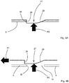
- the hook-shaped element 27 and the recesses 14, 15 are dimensioned so that the hook-shaped element 27 fits in the recesses 14, 15, with the wall portion 28 abutting against an edge 30 of the side wall 4, 5 that bounds the recess 14, 15 (see figure 4A ).
- the slide 3 is preferably made of a plastic material, such as PVC, ABS, PE, PET, PS and PP, to be deformed by means of a thermoforming process. After thermoforming of the slide 3 has taken place, the hook-shaped elements 27 are punched into the upper edge 22, with the desired dimensions of the parts 23, 24, 25, 26 being obtained by said the punching operation.
- the bottom wall 17, the side walls 18, 19, 20, 21 and the upper edge 22 are relatively thin, so that the parts 23, 24 of the upper edge 22 that are provided with the hook-shaped elements 27 can be moved toward each other against the spring force of the material of the slide 3.
- the dimensions of the cardboard housing 2 can vary from, for example, a width of 21 to 151 mm, a height of 51 to 101 mm and a length of 51 to 301 mm.
- the wall thickness of the housing 2 can vary from 400 to 1000 micron, for example.
- the dimensions of the slide 2 can vary from, for example, a width of 20 to 150 mm, a height of 50 to 100 mm and a length of 50 to 300 mm.
- the wall thickness of the slide 3 can vary from 200 to 1000 micron, for example.
- Blister packs present in the slide 3 preferably have dimensions smaller than those of the bottom wall 17 of the slide 3.
- the draft angle of more than 90 degrees between the bottom wall 17 and the side walls 18-20 that is required for the thermoforming of the slide 3 has the advantage in this regard that the side walls 18, 20 are spaced further apart near the upper edge 22 than near the bottom wall 17.
- the side walls 18, 20 can be slightly moved toward each other near the upper side upon elastic deformation of the upper edge 22, without making contact with products present in the slide 3.
- the operation of the package 1 is as follows.
- the flap portion 12 When a user wishes to take products from the slide 3, the flap portion 12 is first pivoted about the pivot line 9 (see figure 2 ). Then the user presses on the hook-shaped elements 27 positioned in the staggered recesses 14 in the directions indicated by the arrows P2, P3 with two fingers, for example the thumb and the index finger.
- the directions indicated by the arrows P2, P3 extend transversely to the sliding direction indicated by the arrow P1. The fingers are thus positioned in the arcuate parts of the recesses 14 in the upper wall 8.
- the staggered hook-shaped elements are moved out of the recesses 14, in the directions indicated by the arrows P2, P3, against spring force and under elastic deformation of the side walls 18, 20 and the parts 23, 24, with the wall portions 28 moving clear of the side walls 5, 6 in question (see figure 4B ).
- the user then takes hold of the wider part 25 of the upper edge 22, which is freely accessible through the opening 13 of the housing 2, whereupon the user moves the slide 3 out of the housing, in the direction indicated by the arrow P1, to the position shown in figure 5 .
- the hook-shaped elements 27 move in the opposite directions of the arrows P2, P3 under the influence of the spring force of the side walls 18, 20 and the parts 23, 24, resulting in the hook-shaped elements 27 being positioned in the recesses 15. Further movement in the sliding direction indicated by the arrow P1 is thus prevented.
- the products (not shown) present in the slide 3 can now be removed from the slide 3. If a user wishes to remove the slide 3 from the housing 2 in its entirety, for example in order to dispose of the plastic slide 3 and the cardboard housing 2 separately, the user will depress the hook-shaped elements 27 positioned in the recesses 15 in the directions indicated by the arrows P2, P3 with two fingers, for example the thumb and the index finger.
- the staggered hook-shaped elements 27 will be moved out of the recesses 15 in the direction indicated by the arrows P2, P3 against spring force and under elastic deformation of the side walls 18, 20 and the parts 23, 24, with the wall portions 28 moving clear of the side walls 5, 6 in question.
- the user will then take hold of the wider part 25 of the upper edge 22 and move the slide 3 out of the housing, in the direction indicated by the arrow P1, to the position shown in figure 6 .
- FIG. 1 Figure schematically shows a second embodiment of a package 101 according to the invention, which is different from the package 1 shown in figures 1-6 in that staggered recesses 14 are only provided at the front side.
- the user will press on hook-shaped elements 27 positioned in the recesses 14 in the directions indicated by the arrows P2, P3 with two fingers, for example the thumb 31 and the index finger 32.
- the user will then take hold of the part of the upper edge that is freely accessible through the opening of the housing 102 with his other hand 33 and move the slide 103 out of the housing in the direction indicated by the arrow P1.
- FIGs 8 and 9 show a third embodiment of a package 201 according to the invention, which is different from the package 1 shown in figures 1-6 , inter alia in that different recesses 215 are located at the front side of the housing 202.
- the recesses 215 are not provided in the upper wall 8 but only in the side walls 5, 6 and have a height which is just slightly greater than the thickness of the hook-shaped elements 27.
- the hook-shaped elements 27 engaging in the recesses 15 prevent the slide 203 from being moved out of the housing 202 in its entirety. Because of the relatively small dimensions of the recesses 215, it will be virtually impossible for a user to push the hook-shaped elements 27 out of the recesses 215.
- the slide 203 of the package 201 is provided with a flexible strip 204, which is provided with a circular attachment part 205 at both ends.
- the flexible strip 205 is attached to the bottom wall 17 of the slide 203 via the circular attachment part 205, for example by being glued or ultrasonically bonded thereto.
- Another circular attachment part 205 of the flexible strip 204 is attached to a blister pack 206.
- Such blister packs 206 for example for tablets, are known per se; they are provided with a number of elevations 207, each of which contains a tablet.
- a cover layer (not shown) is present on a side remote from the elevation 207, which cover layer keeps the tablets in the elevations 207.
- the package 201 comprises a number of flexible strips 204 corresponding to the number of blister packs 206.
- the first flexible strip 204 connects a first blister pack 206 to the slide 203.
- the next flexible strip 204 connects the first blister pack 206 to a second blister pack 206, etc.
- the flexible strips 204 make it possible to stack the blister packs 206 one on top of the other, with the flexible strip 204 being partially positioned between two blister packs 206 disposed one on top of the other (see figure 9 ).
- a single elongated flexible strip extends from the slide 203 over all the blister packs 206 present in the slide 203.
- the blister packs 206 are connected to each other and to the slide 203, a user will be able to remove a product, such as a tablet, from the blister pack 206, but he will not be able to remove an entire blister pack 206 from the package 201. This makes it impossible to store the blister pack 206 outside from the package 201.
- the flexible strip 204 enables a user to place the blister pack 206 in practically any desired position with respect to the slide 203, making it easier to remove a tablet from the blister pack.
- Figures 10-14 show various views of a 1fourth embodiment of a package 301, which is different from the package 1 in that the first side wall 5 is only provided with a recess 14 located between the centre of the side wall 5 and the rear wall 7, and the second side wall 6 is only provided with a recess 14 located between the centre of the side wall 6 and the closable flap 10.
- the slide 3 is provided with two hook-shaped elements 27, which are located at the same relative position as the recesses 14, so that the hook-shaped elements 27 are positioned in the recesses 14 in the position of the slide 3 in the housing 2 that is shown in figure 10 .
- a diagonal line 302 is drawn between the staggered recesses. Said line is not present on the actual package 301 but is only shown by way of illustration of the invention.
- the diagonal line 302 between the staggered recesses 14 in the two side walls 5, 6 includes an angle A at most 60 degrees and at least 20 degrees with the side wall 5, 6.
- the staggered recesses 14 are spaced apart by a distance L of at least 60 mm and at most 120 mm in a direction parallel to the side walls 5, 6. When such dimensions are used, the width B of the package 301 will range between 35 mm and 120 mm, and the length of the diagonal line will range between 70 mm and 140 mm.
- Figure 12 shows a hand 33 of an adult, who can easily depress the staggered hook-shaped elements 27 simultaneously in the directions indicated by the arrows P2 and P3 with his thumb 31 and index finger 32 for releasing the engagement between the slide 3 and the housing 2.
- Figure 13 shows a small hand 33 of a young child of about four years old, who can depress the hook-shaped element 27 near the first wall 5 with his thumb 31 but is unable to simultaneously depress the other hook-shaped element 27 near the second wall 6 with his index finger 32 as well due to the small size of its hand.
- the index finger 32 touches the housing 2 at the location indicated by numeral 303.
- a diagonal line 304 between the hook-shaped element 37 near the first wall 5 and the location 303 includes an angle C of more than 60 degrees with the side walls 5, 6. The child will therefore be unable to unlock the slide 3.
- Figure 14 is a perspective view of the package 301 of figure 10 in a further open position, showing the slide 3 partially moved out of the housing 2.
- Figure 15 is a top plan view of a part 23 of the slide 3 with another embodiment of the hook-shaped element 327.
- the hook-shaped element 327 comprises a wall portion 328 which extends at an acute angle D relative to the part 23 and the sliding direction indicated by the arrow P1, and a wall portion 329 which connects thereto.
- the sloping wall portion 328 gives the hook-shaped element 327 a barb-like configuration, so that the slide 3 must be slidably moved in the opposite direction of the arrow P1 before the hook-shaped element 327 can be pressed through the recess 14. This makes it impossible to pull at the slide 3 and subsequently depress the hook-shaped elements 321 one by one and remove them from the recesses 14.
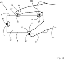
- Figure 16 is a top plan view of a fifth embodiment of a package 401, which is different from the package 1 in that the first side wall 5 is only provided with a recess located near the centre and the second side wall 6 is provided with a recess 14 located between the centre and the rear wall 7 as well as with a recess 14 located between the centre and the closable flap 10.
- the slide 3 is provided with three hook-shaped elements 27, which are located at the same relative position as the recesses 14, so that the hook-shaped elements 27 are positioned in the recesses 14 in the position of the slide 3 in the housing 2 that is shown in figure 16 .
- angles between diagonal lines between the recess 14 in the first side wall 5 on the one hand and the recesses 14 in the side wall 6 on the other hand are less critical in this embodiment than in an embodiment in which only two recesses 14 and two hook-shaped elements 27 are used.
- an adult can depress the hook-shaped element 27 in the recess 14 in the first side wall 5 with his thumb 31 and simultaneously depress the hook-shaped element 27 near the closable flap 10 with his index finger 32 and the hook-shaped element 27 near the rear wall 7 with his middle finger 334.
- Such an operation is virtually impossible to carry out for a child of about four years old in view of its limited motor skills and the size of its hand.
- the upper edge only extends over part of the side walls.
- the slide and the housing can be used different materials for the slide and the housing, such as plastics suitable for thermoforming or injection-moulding, cardboard, especially tear-resistant cardboard, or a metal such as aluminium.
- the recesses are hidden from view by wall portions extending over the recesses.
- Said wall portions must be flexible so that the hook-shaped elements can be pressed out of the recesses located behind the wall portions as a result of pressure being exerted on said wall portions.
- the hook-shaped element may also extend from the flanged-shaped upper edge over part of the side wall.
- the recess must be correspondingly configured in that case. In this way a larger hook-shaped element is obtained.
Landscapes
- Engineering & Computer Science (AREA)
- Mechanical Engineering (AREA)
- Packages (AREA)
Description
- The invention relates to a package comprising a housing and a slide which is slidably accommodated in the housing in a sliding direction, which slide comprises a bottom wall, side walls connected to the bottom wall as well as at least one flange-shaped upper edge spaced from the bottom wall, which is connected to the side walls, which housing is provided with at least one recess, in which at least one projection connected to the slide can be positioned for at least locking the slide in position in the housing, which projection can be moved out of the recess against spring force, after which the slide can be moved in the sliding direction in the housing.
- The invention also relates to a slide and to a housing suitable for such a package.
- Such a package, which is known from
US 7,854,325 B2 , is suitable for use as a childproof, senior-friendly package. To open the package, a user must move the projection out of the recess against spring force by pressing on the housing and subsequently pull the slide out of the housing in the sliding direction. Such combined movements are virtually impossible to carry out for a relatively young child, so that it is prevented from gaining access to products present in the slide, such as medicines, for example. For an older user, on the other hand, said movements are relatively easy to carry out, so that the older user can move the slide out of the housing in order to gain access to products present in the slide. - With the package known from
US 7,854,325 B2 , a bottom side of the housing is provided with a number of guides which are provided with recesses at ends thereof. The slide is provided with projections on the bottom wall, which projections are positioned in the recesses and which are movable in the guides. - The slide is provided with separate spring elements, by means of which the projections are pressed into the recesses.
- The space required for the projections, recesses and guides undesirably adds to the height of the package. In addition, producing a slide which is provided with projections as well as with spring elements and producing a housing provided with relatively complex guides is relatively costly.
- The object of the invention is to provide a package which is childproof and senior-friendly and which is relatively easy to produce.
- This object is achieved with the package according to the invention in that the flange-shaped upper edge comprises two parts that extend parallel to the sliding direction, wherein each part is provided with at least one hook-shaped element, whilst the housing comprises two side walls, wherein each side wall is provided with at least one recess, wherein a recess and a hook-shaped element located at a first side wall are staggered, seen in the sliding direction, relative to a recess and a hook-shaped element located at a second side wall, wherein the hook-shaped elements of the flange-shaped upper edge can be moved out of the recesses against the spring force of the flange-shaped upper edge.
- Because the part of the flange-shaped upper edge that extends parallel to the sliding direction is provided with the hook-shaped element and can also be moved out of the recess against the spring force of the flange-shaped upper edge, separate projections and spring elements are not needed. As a result, the slide is relatively easy to produce. The hook-shaped element can be moved into engagement with the recess located in the side wall of the housing under the spring force of the flange-shaped upper edge. Said recess can be formed in the housing in a simple manner, for example by punching. Once the hook-shaped element has been moved out of the recess against spring force, the slide can be moved in the sliding direction, with the hook-shaped element simply sliding along the inner side of the housing.
- When the slide is pulled at, without the hook-shaped elements being pressed out of the recesses, the hook-shaped elements will prevent the slide from being moved out of the housing.
- The provision of a hook-shaped element that can be positioned in a recess on either side of the package makes it difficult for a child to open the package, because both hook-shaped elements must be removed from the respective recesses simultaneously before the slide can be moved in the sliding direction.
- Moreover, because the hook-shaped elements are staggered, it will be virtually impossible for a young child of about 4 years old to place its fingers so that both staggered hook-shaped elements are removed simultaneously, against spring force, from the likewise staggered recesses.
- According to European and US legislation, a package may be called childproof if it meets the EN/ISO 8317 standard and the US 16 CRF 1700.20 standard, respectively. Both standards prescribe extensive testing both with seniors (50-70 years old) and with children aged about 4 years. The tests are carried out by certified (ISO 17025) test agencies. It has been found that the package according to the invention is able to meet the prevailing standards.
- It is noted that from
JP 09058748A claim 1 20 comprising a housing provided with opposing recesses and a slide with opposing projections. When the slide is being moved out of the housing, the projections slip into the recesses, so that the slide is prevented from falling out of the housing in a simple manner. The projections need not be depressed for moving the slide partially out of the housing. With the package according to the present invention, the hook-shaped elements must first be depressed before the slide can be moved partially out of the housing. - Another package having a housing and slide is known from
EP 0 053 593 . - One embodiment of the package according to the invention is characterised in that a diagonal line between the staggered recesses in the two side walls includes an angle of at most 60 degrees with the side wall.
- The smaller the angle between the diagonal line and the side wall provided with the recess, the more difficult it will be to open the package. With a package of a particular width, the diagonal distance between the staggered recesses and the hook-shaped elements positioned therein will be larger in the case of a smaller angle than in the case of a larger angle. If the angle is too small, it will be difficult for adults, and certainly also for seniors, to open the package. Consequently, the angle is preferably larger than 20 degrees.
- Another embodiment of the package according to the invention is characterised in that the staggered recesses in the two side walls are spaced a distance of at least 60 mm apart, seen in a direction parallel to the side wall.
- The greater the distance, the more difficult it will be to open the package. If the distance is too great, it will be difficult for adults, and certainly also for seniors, to open the package. Consequently, the distance is preferably less than 120 mm.
- Another embodiment of the package according to the invention is characterised in that the hook-shaped element has a barb-like configuration.
- The barb-like configuration makes it impossible to depress the hook-shaped element whilst the slide is being pulled at. This makes it impossible to pull at the slide and subsequently depress the hook-shaped elements one by one and remove them from the recesses. The barb-like configuration forces the user to depress both hook-shaped elements simultaneously.
- Another embodiment of the package according to the invention is characterised in that the recess provided in the first side wall is staggered relative to two recesses provided in the second side wall, whilst the slide is provided with three hook-shaped elements that can be moved out of the three recesses simultaneously against the spring force of the flange-shaped upper edge.
- The fact that three hook-shaped elements must be depressed simultaneously makes it even more difficult to open the package.
- Products such as medicines can be easily stored in the slide. The medicines, such as tablets, for example, may be packed in a blister pack, for example, a number of which blister packs are present in the slide.
- Another embodiment of the package according to the invention is characterised in that the hook-shaped element lies in the same plane as the part of the flange-shaped upper edge that extends parallel to the sliding direction.
- Such a hook-shaped element is easy to form in the flange-shaped upper edge, for example by punching. The hook-shaped element will in that case have the same relatively small thickness as the flange-shaped upper edge. In this way the recess present in the housing can likewise have a relatively small dimension in the thickness direction of the hook-shaped element. As a result, the strength of the housing will remain practically unchanged in spite of the presence of the recess therein.
- Another embodiment of the package according to the invention is characterised in that the side wall of the housing is provided with at least two spaced-apart recesses.
- In a first position, in which the slide is fully accommodated within the housing, the hook-shaped element is positioned in a first recess. In a second position, in which the slide is partially moved out of the housing, the hook-shaped element is positioned in a second recess. In this way the slide is prevented from being moved completely out of the housing in a simple manner, so that moving back the slide into the housing will be relatively easy. In addition, this makes it impossible for a user to move the slide into another housing, which might involve the risk that the information stated on the housing would no longer correspond to the medicines present in the slide.
- Another embodiment of the package according to the invention is characterised in that the at least one recess is partially located in an upper wall of the housing.
- The hook-shaped element only engages the side wall. Because the recess also extends over the upper wall, a user can simply place his finger against the hook-shaped element and move it away from the side wall against spring force, out of engagement with the side wall.
- Another embodiment of the package according to the invention is characterised in that the housing comprises an upper wall which is provided with an opening at a front side, seen in the sliding direction, via which opening access can be gained to a part of the flange-shaped upper edge that extends transversely to the sliding direction.
- Through the opening, a user can easily take hold of the part of the flange-shaped upper edge that extends transversely to the sliding direction after the hook-shaped element has been moved out of engagement with the recess in order to pull the slide out of the housing in the sliding direction.
- Another embodiment of the package according to the invention is characterised in that the housing is provided with a closable flap.
- The flap makes it extra difficult to gain access to the slide. The flap must first be opened before the slide can be moved out of the housing. In the closed position of the flap, the flap protects the slide and the products present therein from the ingress of dust and the like.
- Another embodiment of the package according to the invention is characterised in that the housing is closed at a rear side, seen in the sliding direction.
- The closed rear side makes it extra difficult to gain access to the slide.
- Another embodiment of the package according to the invention is characterised in that the slide is made of plastic material, using a thermoforming process.
- This is a relatively inexpensive manner of producing the slide. When a thermoforming process is used, the flange-shaped upper edge must be punched to the desired dimensions after the forming of the slide. During this usual punching operation, the hook-shaped element is simultaneously formed on the flange-shaped upper edge by means of a punching operation. As a result, additional operations for providing the slide with the hook-shaped elements are not needed.
- Another embodiment of the package according to the invention is characterised in that the housing is made of cardboard.
- Such a cardboard housing is usually punched from a blank. During this usual punching operation, the recess in the side wall, and possibly the upper wall, is simultaneously formed by punching. As a result, additional operations for providing the housing with the recess are not needed.
- The invention will now be explained in more detail with reference to the drawings, in which:
-
Figure 1 is a perspective view of a first embodiment of a package according to the invention in a fully closed position; -
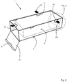
Figure 2 is a perspective view of the package shown infigure 1 in a partially open position; -
Figure 3 is a perspective detail view of the package shown infigure 2 ; -
Figures 4A and 4B are schematic top plan views of the package shown infigure 2 prior to and after the removal of the hook-shaped element from the recess, respectively; -
Figure 5 is a perspective view of the package shown infigure 1 in a further open position; -
Figure 6 is a perspective view of the package shown infigure 1 in a fully open position; -
Figure 7 is a perspective top plan view of a part of a second embodiment of a package according to the invention; -
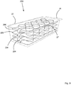
Figure 8 is a perspective view of a third embodiment of a package according to the invention with folded-out blister packs; -
Figure 9 is a perspective view of the slide of the package shown infigure 1 with folded-up blister packs; -
Figure 10 is a perspective view of a fourth embodiment of a package according to the invention in a partially open position; -
Figure 11 is a top plan view of the package shown infigure 10 ; -
Figure 12 shows the top plan view offigure 11 of the package shown infigure 10 with a hand of an adult; -
Figure 13 shows the top plan view offigure 11 of the package shown infigure 10 with a hand of a small child; -
Figure 14 is a perspective view of the package shown infigure 10 in a further open position; -
Figure 15 is a top plan view of a part of the slide with another embodiment of the hook-shaped element; -
Figure 16 is a top plan view showing a fifth embodiment of a package according to the invention provided with three recesses and three hook-shaped elements, as well as a hand of an adult. - Like parts are indicated by the same numerals in the figures.
-
Figures 1-6 show various views of a first embodiment of apackage 1 according to the invention. The package comprises acardboard housing 2 and aslide 3 of plastic material, which is slidably accommodated, in the direction indicated by arrow P1, in thehousing 2. Thehousing 2 comprises abottom side 4,side walls bottom side 4, arear wall 7 extending transversely to thebottom side 4 and theside walls upper wall 8 extending parallel to the bottom side, and aflap 10 which is pivotally connected about apivot line 9 to the bottom side. Theflap 10 is provided with aflap portion 12 which is pivotable about apivot line 11, whichflap portion 12 can be positioned to abut against theupper wall 8 on an inner side. Such arectangular housing 2 is known per se and will not be discussed in more detail herein, therefore. - On a side remote from the
rear wall 7, theupper wall 8 of thehousing 2 is provided with asemicircular opening 13. - The
housing 2 is provided with two pairs ofrecesses side walls upper wall 8 and the sides of theupper wall 8 that face theside walls recesses side walls recesses upper wall 8 is arcuate in shape. Therecesses 14 are located relatively close to therear wall 7, whilst therecesses 15 are located relatively close to theflap 10. Therecesses first side wall 5 are staggered relative to therecesses second side wall 6 in the sliding direction indicated by the arrow P1. - The
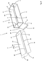
slide 3 comprises abottom wall 17 andside walls bottom wall 17, which each include an angle slightly greater than 90 degrees with thebottom wall 17. Theslide 3 further comprises a flange-shaped, endlessupper edge 22, spaced from thebottom wall 17, which is connected to theside walls upper edge 22 comprises twoparts parts part 25 is wider than thepart 26. - The
parts element 27, spaced from thewider part 25. The hook-shapedelements 27 are staggered in the sliding direction indicated by the arrow P1, similarly to therecesses housing 2. In a direction transversely to thebottom wall 17, the hook-shapedelement 27 has the same thickness as theupper edge 22. - As is clearly shown in
figures 4A and 4B , the hook-shapedelement 27 comprises awall portion 28 extending transversely to the sliding direction indicated by the arrow P1 and acurved wall portion 29 connecting thereto. Thewall portion 28 is located on a side of the hook-shapedelement 27 that faces thewider part 25. The hook-shapedelement 27 and therecesses element 27 fits in therecesses wall portion 28 abutting against anedge 30 of theside wall recess 14, 15 (seefigure 4A ). - The
slide 3 is preferably made of a plastic material, such as PVC, ABS, PE, PET, PS and PP, to be deformed by means of a thermoforming process. After thermoforming of theslide 3 has taken place, the hook-shapedelements 27 are punched into theupper edge 22, with the desired dimensions of theparts bottom wall 17, theside walls upper edge 22 are relatively thin, so that theparts upper edge 22 that are provided with the hook-shapedelements 27 can be moved toward each other against the spring force of the material of theslide 3. - The dimensions of the
cardboard housing 2 can vary from, for example, a width of 21 to 151 mm, a height of 51 to 101 mm and a length of 51 to 301 mm. The wall thickness of thehousing 2 can vary from 400 to 1000 micron, for example. - The dimensions of the
slide 2 can vary from, for example, a width of 20 to 150 mm, a height of 50 to 100 mm and a length of 50 to 300 mm. The wall thickness of theslide 3 can vary from 200 to 1000 micron, for example. - Blister packs present in the
slide 3 preferably have dimensions smaller than those of thebottom wall 17 of theslide 3. The draft angle of more than 90 degrees between thebottom wall 17 and the side walls 18-20 that is required for the thermoforming of theslide 3 has the advantage in this regard that theside walls upper edge 22 than near thebottom wall 17. As a result, theside walls upper edge 22, without making contact with products present in theslide 3. - The operation of the
package 1 is as follows. - In the closed position of the
package 1 that is shown infigure 1 , theslide 3 is fully enclosed within thehousing 2, and theflap 10 is in the closed position. Theslide 3 is now hidden from view and access to the products present therein, such as loose medicines or tablet blister packs, is not possible. In the closed position, the hook-shapedelements 27 of theslide 3 are positioned in therecesses 14 of the housing (seefigure 4A ). - When a user wishes to take products from the
slide 3, theflap portion 12 is first pivoted about the pivot line 9 (seefigure 2 ). Then the user presses on the hook-shapedelements 27 positioned in thestaggered recesses 14 in the directions indicated by the arrows P2, P3 with two fingers, for example the thumb and the index finger. The directions indicated by the arrows P2, P3 extend transversely to the sliding direction indicated by the arrow P1. The fingers are thus positioned in the arcuate parts of therecesses 14 in theupper wall 8. The staggered hook-shaped elements are moved out of therecesses 14, in the directions indicated by the arrows P2, P3, against spring force and under elastic deformation of theside walls parts wall portions 28 moving clear of theside walls figure 4B ). Using his other hand, the user then takes hold of thewider part 25 of theupper edge 22, which is freely accessible through theopening 13 of thehousing 2, whereupon the user moves theslide 3 out of the housing, in the direction indicated by the arrow P1, to the position shown infigure 5 . In this partially open position, the hook-shapedelements 27 move in the opposite directions of the arrows P2, P3 under the influence of the spring force of theside walls parts elements 27 being positioned in therecesses 15. Further movement in the sliding direction indicated by the arrow P1 is thus prevented. The products (not shown) present in theslide 3 can now be removed from theslide 3. If a user wishes to remove theslide 3 from thehousing 2 in its entirety, for example in order to dispose of theplastic slide 3 and thecardboard housing 2 separately, the user will depress the hook-shapedelements 27 positioned in therecesses 15 in the directions indicated by the arrows P2, P3 with two fingers, for example the thumb and the index finger. As a result, the staggered hook-shapedelements 27 will be moved out of therecesses 15 in the direction indicated by the arrows P2, P3 against spring force and under elastic deformation of theside walls parts wall portions 28 moving clear of theside walls wider part 25 of theupper edge 22 and move theslide 3 out of the housing, in the direction indicated by the arrow P1, to the position shown infigure 6 . - If a relatively young child undesirably attempts to open the
package 1, it will presumably be able to open theflap 10. The child will then pull at thewider part 25 of theupper edge 22, which is freely accessible through theopening 13 of thehousing 2. However, because thewall portions 28 of the hook-shapedelements 27 abut against theedge 30 of theside walls 4, 5 (seefigure 4A ), moving theslide 3 out of thehousing 2 is prevented in a simple manner. - Figure schematically shows a second embodiment of a
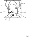
package 101 according to the invention, which is different from thepackage 1 shown infigures 1-6 in that staggered recesses 14 are only provided at the front side. In this embodiment, too, the user will press on hook-shapedelements 27 positioned in therecesses 14 in the directions indicated by the arrows P2, P3 with two fingers, for example thethumb 31 and theindex finger 32. The user will then take hold of the part of the upper edge that is freely accessible through the opening of thehousing 102 with hisother hand 33 and move theslide 103 out of the housing in the direction indicated by the arrow P1. -
Figures 8 and9 show a third embodiment of apackage 201 according to the invention, which is different from thepackage 1 shown infigures 1-6 , inter alia in thatdifferent recesses 215 are located at the front side of thehousing 202. Therecesses 215 are not provided in theupper wall 8 but only in theside walls elements 27. As a result, the hook-shapedelements 27 engaging in therecesses 15 prevent theslide 203 from being moved out of thehousing 202 in its entirety. Because of the relatively small dimensions of therecesses 215, it will be virtually impossible for a user to push the hook-shapedelements 27 out of therecesses 215. - The
slide 203 of thepackage 201 is provided with aflexible strip 204, which is provided with acircular attachment part 205 at both ends. Theflexible strip 205 is attached to thebottom wall 17 of theslide 203 via thecircular attachment part 205, for example by being glued or ultrasonically bonded thereto. Anothercircular attachment part 205 of theflexible strip 204 is attached to ablister pack 206.Such blister packs 206, for example for tablets, are known per se; they are provided with a number ofelevations 207, each of which contains a tablet. A cover layer (not shown) is present on a side remote from theelevation 207, which cover layer keeps the tablets in theelevations 207. Thepackage 201 comprises a number offlexible strips 204 corresponding to the number of blister packs 206. The firstflexible strip 204 connects afirst blister pack 206 to theslide 203. The nextflexible strip 204 connects thefirst blister pack 206 to asecond blister pack 206, etc. Theflexible strips 204 make it possible to stack theblister packs 206 one on top of the other, with theflexible strip 204 being partially positioned between twoblister packs 206 disposed one on top of the other (seefigure 9 ). - According to another possibility, a single elongated flexible strip extends from the
slide 203 over all theblister packs 206 present in theslide 203. - Because the
blister packs 206 are connected to each other and to theslide 203, a user will be able to remove a product, such as a tablet, from theblister pack 206, but he will not be able to remove anentire blister pack 206 from thepackage 201. This makes it impossible to store theblister pack 206 outside from thepackage 201. - The
flexible strip 204 enables a user to place theblister pack 206 in practically any desired position with respect to theslide 203, making it easier to remove a tablet from the blister pack. -
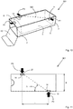
Figures 10-14 show various views of a 1fourth embodiment of apackage 301, which is different from thepackage 1 in that thefirst side wall 5 is only provided with arecess 14 located between the centre of theside wall 5 and therear wall 7, and thesecond side wall 6 is only provided with arecess 14 located between the centre of theside wall 6 and theclosable flap 10. Theslide 3 is provided with two hook-shapedelements 27, which are located at the same relative position as therecesses 14, so that the hook-shapedelements 27 are positioned in therecesses 14 in the position of theslide 3 in thehousing 2 that is shown infigure 10 . - A
diagonal line 302 is drawn between the staggered recesses. Said line is not present on theactual package 301 but is only shown by way of illustration of the invention. Thediagonal line 302 between thestaggered recesses 14 in the twoside walls side wall side walls package 301 will range between 35 mm and 120 mm, and the length of the diagonal line will range between 70 mm and 140 mm. -
Figure 12 shows ahand 33 of an adult, who can easily depress the staggered hook-shapedelements 27 simultaneously in the directions indicated by the arrows P2 and P3 with histhumb 31 andindex finger 32 for releasing the engagement between theslide 3 and thehousing 2. -
Figure 13 shows asmall hand 33 of a young child of about four years old, who can depress the hook-shapedelement 27 near thefirst wall 5 with histhumb 31 but is unable to simultaneously depress the other hook-shapedelement 27 near thesecond wall 6 with hisindex finger 32 as well due to the small size of its hand. Theindex finger 32 touches thehousing 2 at the location indicated bynumeral 303. Adiagonal line 304 between the hook-shaped element 37 near thefirst wall 5 and thelocation 303 includes an angle C of more than 60 degrees with theside walls slide 3. -
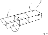
Figure 14 is a perspective view of thepackage 301 offigure 10 in a further open position, showing theslide 3 partially moved out of thehousing 2. -
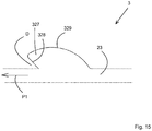
Figure 15 is a top plan view of apart 23 of theslide 3 with another embodiment of the hook-shapedelement 327. As is clearly shown infigure 15 , the hook-shapedelement 327 comprises awall portion 328 which extends at an acute angle D relative to thepart 23 and the sliding direction indicated by the arrow P1, and awall portion 329 which connects thereto. Thesloping wall portion 328 gives the hook-shaped element 327 a barb-like configuration, so that theslide 3 must be slidably moved in the opposite direction of the arrow P1 before the hook-shapedelement 327 can be pressed through therecess 14. This makes it impossible to pull at theslide 3 and subsequently depress the hook-shaped elements 321 one by one and remove them from therecesses 14. -
Figure 16 is a top plan view of a fifth embodiment of apackage 401, which is different from thepackage 1 in that thefirst side wall 5 is only provided with a recess located near the centre and thesecond side wall 6 is provided with arecess 14 located between the centre and therear wall 7 as well as with arecess 14 located between the centre and theclosable flap 10. Theslide 3 is provided with three hook-shapedelements 27, which are located at the same relative position as therecesses 14, so that the hook-shapedelements 27 are positioned in therecesses 14 in the position of theslide 3 in thehousing 2 that is shown infigure 16 . - The angles between diagonal lines between the
recess 14 in thefirst side wall 5 on the one hand and therecesses 14 in theside wall 6 on the other hand are less critical in this embodiment than in an embodiment in which only tworecesses 14 and two hook-shapedelements 27 are used. To move theslide 3 out of thehousing 2, an adult can depress the hook-shapedelement 27 in therecess 14 in thefirst side wall 5 with histhumb 31 and simultaneously depress the hook-shapedelement 27 near theclosable flap 10 with hisindex finger 32 and the hook-shapedelement 27 near therear wall 7 with hismiddle finger 334. Such an operation is virtually impossible to carry out for a child of about four years old in view of its limited motor skills and the size of its hand. - According to another possibility, the upper edge only extends over part of the side walls.
- It is also possible to use different materials for the slide and the housing, such as plastics suitable for thermoforming or injection-moulding, cardboard, especially tear-resistant cardboard, or a metal such as aluminium.
- It is also possible to provide the slide with two pairs of hook-shaped elements and to provide the housing with a single pair of recesses near the front side of the housing in order to define a closed position and a partially open position.
- It is also possible to provide the slide with a single pair of hook-shaped elements and to provide the housing with a single pair of recesses so as to define only a closed position in the package.
- According to another possibility, the recesses are hidden from view by wall portions extending over the recesses. Said wall portions must be flexible so that the hook-shaped elements can be pressed out of the recesses located behind the wall portions as a result of pressure being exerted on said wall portions.
- The hook-shaped element may also extend from the flanged-shaped upper edge over part of the side wall. The recess must be correspondingly configured in that case. In this way a larger hook-shaped element is obtained.
-
- 1
- package
- 2
- housing
- 3
- slide
- 4
- bottom side
- 5
- side wall
- 6
- side wall
- 7
- rear wall
- 8
- upper wall
- 9
- pivot line
- 10
- flap
- 11
- pivot line
- 12
- flap portion
- 13
- opening
- 14
- recess
- 15
- recess
- 17
- bottom wall
- 18
- side wall
- 19
- side wall
- 20
- side wall
- 21
- side wall
- 22
- upper edge
- 23
- part
- 24
- part
- 25
- part
- 26
- part
- 27
- hook-shaped element
- 28
- wall portion
- 29
- wall portion
- 30
- edge
- 31
- thumb
- 32
- index finger
- 33
- hand
- 101
- package
- 102
- housing
- 103
- slide
- 201
- package
- 202
- housing
- 203
- slide
- 204
- strip
- 205
- circular attachment part
- 206
- blister pack
- 207
- elevations
- 215
- recesses
- 301
- package
- 302
- diagonal line
- 327
- hook-shaped element
- 328
- wall portion
- 329
- wall portion
- 401
- package
- 334
- middle finger
- A
- angle
- B
- width
- C
- angle
- D
- angle
- L
- distance
- P1
- arrow
- P2
- arrow
- P3
- arrow
Claims (15)
- A package (1, 101, 201, 301, 401) comprising a housing (2, 102, 202) and a slide (3, 103, 203) which is slidably accommodated in the housing (2, 102, 202) in a sliding direction P1, which slide (3, 103, 203) comprises a bottom wall (17), side walls (18-21) connected to the bottom wall (17) as well as at least one flange-shaped upper edge (22) spaced from the bottom wall (17), which is connected to the side walls (18-21), which housing (2, 102, 202) is provided with at least one recess (14, 15), in which at least one projection connected to the slide (3, 103, 203) can be positioned for at least locking the slide (3, 103, 203) in position in the housing (2, 102, 202), which projection can be moved out of the recess (14, 15) against spring force, after which the slide (3, 103, 203) can be moved in the sliding direction (P1) in the housing (2, 102, 202), wherein the flange-shaped upper edge (22) comprises two parts that extend parallel to the sliding direction (P1), wherein each part is provided with at least one hook-shaped element (27, 327), whilst the housing (2, 102, 202) comprises two side walls (5, 6), wherein each side wall is provided with at least one recess (14, 15), characterised in that a recess (14, 15) and a hook-shaped element (27, 327) located at a first side wall are staggered, seen in the sliding direction (P1), relative to a recess (14, 15) and a hook-shaped element (27, 327) located at a second side wall, wherein the hook-shaped elements (27, 327) of the flange-shaped upper edge (22) can be moved out of the recesses (14, 15) against the spring force of the flange-shaped upper edge (22).
- A package (1, 101, 201, 301, 401) according to claim 1, characterised in that a diagonal line between the staggered recesses in the two side walls includes an angle of at most 60 degrees with the side wall.
- A package (1, 101, 201, 301, 401) according to claim 1 or 2, characterised in that the staggered recesses in the two side walls are spaced a distance of at least 60 mm apart, seen in a direction parallel to the side wall.
- A package (1, 101, 201, 301, 401) according to any one of the preceding claims, characterised in that the hook-shaped element (27, 327) has a barb-like configuration.
- A package (1, 101, 201, 301, 401) according to any one of the preceding claims, characterised in that the recess provided in the first side wall is staggered relative to two recesses provided in the second side wall, whilst the slide is provided with three hook-shaped elements (27, 327) that can be moved out of the three recesses (14, 15) simultaneously against the spring force of the flange-shaped upper edge (22).
- A package (1, 101, 201, 301, 401) according to any one of the preceding claims, characterised in that the hook-shaped element (27, 327) lies in the same plane as the part of the flange-shaped upper edge (22) that extends parallel to the sliding direction (P1).
- A package (1, 101, 201, 301, 401) according to any one of the preceding claims, characterised in that the side wall of the housing (2, 102, 202) is provided with at least two spaced-apart recesses (14, 15).
- A package (1, 101, 201, 301, 401) according to any one of the preceding claims, characterised in that the at least one recess (14, 15) is partially located in an upper wall (8) of the housing (2, 102, 202).
- A package (1, 101, 201, 301, 401) according to any one of the preceding claims, characterised in that the housing (2, 102, 202) comprises an upper wall (8) which is provided with an opening (13) at a front side, seen in the sliding direction (P1), via which opening (13) access can be gained to a part of the flange-shaped upper edge (22) that extends transversely to the sliding direction (P1).
- A package (1, 101, 201, 301, 401) according to any one of the preceding claims, characterised in that the housing (2, 102, 202) is provided with a closable flap.
- A package (1, 101, 201, 301, 401) according to any one of the preceding claims, characterised in that the housing (2, 102, 202) is closed at a rear side, seen in the sliding direction (P1).
- A package (1, 101, 201, 301, 401) according to any one of the preceding claims, characterised in that the slide (3, 103, 203) is made of plastic material, using a thermoforming process.
- A package (1, 101, 201, 301, 401) according to any one of the preceding claims, characterised in that the housing (2, 102, 202) is made of cardboard.
- A slide (3, 103, 203) suitable for a package (1, 101, 201) according to any one of the preceding claims, wherein said slide comprises a bottom wall (17), side walls (18-21) connected to the bottom wall as well as at least one flange-shaped upper edge (22) spaced from the bottom wall, which is connected to the side walls, wherein the flange-shaped upper edge comprises two parts that extend parallel to the sliding direction (P1), wherein each part is provided with at least one hook-shaped element (27, 327), wherein a hook-shaped element located at a first side wall is staggered, seen in the sliding direction, relative to a hook-shaped element (27, 327) located at a second side wall.
- A housing (2, 102, 202) suitable for a package (1, 101, 201) according to any one of the preceding claims, 1-13, wherein said housing is provided with at least one recess (14, 15), in which at least one projection connected to a slide can be positioned for at least locking a slide in position in the housing, wherein said housing comprises two side walls (5, 6), each side walls being provided with at least one recess (14, 15), wherein a recess located at a first side wall is staggered, seen in a sliding direction (P1), relative to a recess located at a second side wall.
Applications Claiming Priority (2)
| Application Number | Priority Date | Filing Date | Title |
|---|---|---|---|
| NL2011090A NL2011090C2 (en) | 2013-07-04 | 2013-07-04 | PACKAGING AND BAD AND HOUSING SUITABLE FOR SUCH PACKAGING. |
| PCT/EP2014/063956 WO2015000896A1 (en) | 2013-07-04 | 2014-07-01 | A package as well as a slide and a housing suitable for such a package |
Publications (2)
| Publication Number | Publication Date |
|---|---|
| EP3016883A1 EP3016883A1 (en) | 2016-05-11 |
| EP3016883B1 true EP3016883B1 (en) | 2017-03-08 |
Family
ID=49261706
Family Applications (1)
| Application Number | Title | Priority Date | Filing Date |
|---|---|---|---|
| EP14736717.1A Active EP3016883B1 (en) | 2013-07-04 | 2014-07-01 | A package as well as a slide and a housing suitable for such a package |
Country Status (6)
| Country | Link |
|---|---|
| US (1) | US9725206B2 (en) |
| EP (1) | EP3016883B1 (en) |
| JP (1) | JP6370897B2 (en) |
| ES (1) | ES2628254T3 (en) |
| NL (1) | NL2011090C2 (en) |
| WO (1) | WO2015000896A1 (en) |
Cited By (2)
| Publication number | Priority date | Publication date | Assignee | Title |
|---|---|---|---|---|
| US11214400B2 (en) | 2018-06-14 | 2022-01-04 | Ecobliss Holding B.V. | Package and a slide for such a package |
| NL2032716B1 (en) | 2022-08-10 | 2024-02-16 | Ecobliss Holding B V | A package as well as a slide and a blank suitable for such a package |
Families Citing this family (37)
| Publication number | Priority date | Publication date | Assignee | Title |
|---|---|---|---|---|
| NL2011090C2 (en) | 2013-07-04 | 2015-01-06 | Ecobliss Holding B V | PACKAGING AND BAD AND HOUSING SUITABLE FOR SUCH PACKAGING. |
| US9278792B2 (en) * | 2014-07-31 | 2016-03-08 | Ecobliss Holding B.V. | Package for products packed in blister packs, a tray-shaped slide suitable for such a package, a blister pack suitable for such a package as well as a housing suitable for such a package |
| NL2014275B1 (en) * | 2015-02-11 | 2016-10-13 | Ecobliss Holding B V | A package as well as a slide and a housing suitable for such a package. |
| US9783335B2 (en) | 2015-02-27 | 2017-10-10 | Munson Whitman Everett | Child-resistant packaging systems and methods |
| EP3261941B1 (en) * | 2015-02-27 | 2020-04-22 | Everett, Munson Whitman | Child-resistant package |
| JP6547591B2 (en) * | 2015-11-02 | 2019-07-24 | 大日本印刷株式会社 | Composite container |
| GB201601626D0 (en) * | 2016-01-28 | 2016-03-16 | Duff Design Ltd | Latchable package |
| CA2964207C (en) * | 2016-04-14 | 2023-01-31 | All Packaging Company | Locking packaging container |
| US10518927B2 (en) * | 2016-04-14 | 2019-12-31 | All Packaging Company | Locking packaging container |
| IT201700005523A1 (en) * | 2017-01-19 | 2018-07-19 | Tecnoform S R L | PACKAGE |
| CA3089497C (en) * | 2018-03-09 | 2024-04-09 | Contempo Card Company | Child resistant storage container |
| NL2020744B1 (en) | 2018-04-11 | 2019-10-22 | Ecobliss Holding B V | Method of medication dosing as well as a system of medication dosing |
| US10968014B2 (en) * | 2018-04-28 | 2021-04-06 | HLP Clear Packaging Products (USA), Inc. | Locking package |
| WO2019226779A1 (en) * | 2018-05-22 | 2019-11-28 | Diamond Packaging | Locking packaging container |
| ES1215904Y (en) | 2018-06-15 | 2018-10-22 | Acondicionamiento Tarrasense | PACK WITH SAFETY OPENING |
| CN108928529B (en) * | 2018-08-13 | 2020-08-11 | 新协力包装制品(深圳)有限公司 | Packing box (Chinese character' jiangsu |
| USD897831S1 (en) | 2018-10-10 | 2020-10-06 | Berlin Packaging, Llc | Container tray assembly with child resistant sleeve |
| US10683137B2 (en) | 2018-10-10 | 2020-06-16 | Berlin Packaging, Llc | Container tray assembly with child resistant sleeve |
| GB2586471B (en) * | 2019-08-19 | 2021-11-17 | Smol Ltd | Child-resistant package |
| CN114555486A (en) * | 2019-09-04 | 2022-05-27 | 凯思派克有限公司 | Portable container system and method of making same |
| BE1027591B1 (en) * | 2019-09-23 | 2021-04-21 | Deca Packaging Group Verkort Deca Nv | Child-safe packaging |
| US11840381B2 (en) * | 2019-10-10 | 2023-12-12 | Jam Packaging Llc | Child resistant lockable container |
| EP4045417A4 (en) * | 2019-10-15 | 2023-11-08 | All Packaging Company LLC | Locking packaging container |
| CA3158449A1 (en) * | 2019-11-15 | 2021-05-20 | Jinmeng LI | Safety box capable of preventing opening by infant and opening method |
| DE102019133297A1 (en) * | 2019-12-06 | 2021-06-10 | Focke & Co. (Gmbh & Co. Kg) | Pack with opening lock, especially child-resistant pack |
| DE102019133300A1 (en) * | 2019-12-06 | 2021-06-10 | Focke & Co. (Gmbh & Co. Kg) | Pack with opening lock, especially child-resistant pack |
| DE102019133299A1 (en) | 2019-12-06 | 2021-06-10 | Focke & Co. (Gmbh & Co. Kg) | Pack with opening lock, especially child-resistant pack |
| ES2932508T3 (en) * | 2020-05-08 | 2023-01-20 | Procter & Gamble | Detergent product container with closure |
| CN113002987A (en) * | 2021-02-22 | 2021-06-22 | 浙江顺福印业有限公司 | Packing carton with anti-fake structure |
| EP4071073B1 (en) * | 2021-04-06 | 2023-09-27 | Fameccanica.Data S.p.A. | Child-proof paper or cardboard container |
| US20220363458A1 (en) * | 2021-05-14 | 2022-11-17 | Altria Client Services Llc | Package with opposing locking mechanisms |
| NL2029481B1 (en) * | 2021-10-21 | 2023-05-16 | Ecobliss Holding B V | A package as well as a slide suitable for such a package |
| US20230150737A1 (en) * | 2021-11-09 | 2023-05-18 | Kacepack Ltd. | Child-resistant container |
| USD1038561S1 (en) | 2022-01-11 | 2024-08-06 | Nantucket Spider, LLC | Stacked arrangement of water-soluble cleaning strips and child-resistant container |
| US11820567B2 (en) * | 2022-03-21 | 2023-11-21 | Sunshine Enclosures LLC | Pressure sensitive flexible button lock and retractable package thereof |
| CA3265507A1 (en) * | 2022-08-25 | 2024-02-29 | Graphic Packaging International, Llc | Tray and sleeve with locking features, related systems and methods |
| DE202022104856U1 (en) | 2022-08-29 | 2024-01-11 | Gpi Frankfurt & Augsburg Gmbh | Folding box with click tabs |
Family Cites Families (32)
| Publication number | Priority date | Publication date | Assignee | Title |
|---|---|---|---|---|
| US3942630A (en) * | 1974-11-22 | 1976-03-09 | International Tools (1973) Limited | Sliding cover safety package |
| US4126224A (en) * | 1977-11-03 | 1978-11-21 | Laauwe Robert H | Moisture-proof and child-resistant pill box |
| US4284204A (en) * | 1979-11-07 | 1981-08-18 | American Safety Razor Company | Dimpled tray package with self-locking feature |
| JPS56125816U (en) * | 1980-02-26 | 1981-09-25 | ||
| SE433341B (en) * | 1980-11-27 | 1984-05-21 | Gunnar Anjou | CHILDREN'S ASK |
| JP3654968B2 (en) * | 1995-08-11 | 2005-06-02 | 大日本印刷株式会社 | Sleeve type simultaneous opening carton |
| CA2207045C (en) | 1996-07-22 | 1999-06-01 | Michel Bouthiette | Kit and process for the manufacture of a set of individual pill containers |
| US5882611A (en) * | 1997-06-02 | 1999-03-16 | Ethicon, Inc. | Cassette and delivery system |
| JP2007511432A (en) | 2003-11-13 | 2007-05-10 | ミードウエストベコ・コーポレーション | Packaging system that children can not mischief and method of making this |
| BRPI0506728A (en) | 2004-01-07 | 2007-05-02 | Meadwestvaco Corp | packing |
| US7188729B2 (en) | 2005-01-20 | 2007-03-13 | Dejonge Associates, Inc. | Child resistant blister pack container for stacked blister packs |
| US20060157375A1 (en) | 2005-01-20 | 2006-07-20 | Dejonge Stuart W | Child resistant blister pack container for stacked blister packs with non-coincidental notching |
| PE20070251A1 (en) | 2005-06-17 | 2007-03-23 | Novartis Ag | CONTAINER TO SUPPLY INDIVIDUAL BAGS |
| WO2008061026A2 (en) | 2006-11-12 | 2008-05-22 | Meadwestvaco Corporation | Blister pack container |
| WO2011153290A1 (en) | 2010-06-01 | 2011-12-08 | Meadwestvaco Corporation | Single piece container for securing an insert card |
| US7798329B2 (en) * | 2007-04-19 | 2010-09-21 | Meadwestvaco Corporation | Insert package |
| US20080283434A1 (en) * | 2007-05-17 | 2008-11-20 | Gelardi John A | Selectably Lockable Case |
| US20090255842A1 (en) | 2008-04-09 | 2009-10-15 | Rexam Closure Systems Inc. | Child-resistant compact for blister card products |
| EP2110333B1 (en) * | 2008-04-14 | 2011-09-14 | Uhlmann Pac-Systeme GmbH & Co. KG | Child-proof packaging |
| GB0813937D0 (en) | 2008-07-31 | 2008-09-03 | Meadwestvaco Corp | Container for housing a tray or blister pack |
| US20110226765A1 (en) | 2008-12-09 | 2011-09-22 | Meadwestvaco Corporation | Package for securing a multi-pack traveler component |
| US8066122B2 (en) | 2009-04-01 | 2011-11-29 | Berry Plastics Corporation | Child-resistant package with pivotable blister card |
| US8220636B2 (en) | 2009-04-21 | 2012-07-17 | Berry Plastics Corporation | Child-resistant multi-blister card case |
| US7967144B2 (en) * | 2009-11-09 | 2011-06-28 | Anderson Packaging, Inc. | Child-resistant, senior-friendly package having a squeeze-release mechanism and method of assembly |
| JP2011121625A (en) * | 2009-12-14 | 2011-06-23 | Sanyo Electric Co Ltd | Packaging member and case |
| US8342330B2 (en) | 2010-07-19 | 2013-01-01 | Key-Pak Technologies, Llc | Child-resistant and senior-friendly eco-friendly pill dispenser blister package |
| US8991606B2 (en) | 2010-08-24 | 2015-03-31 | Mallinckrodt Llc | Pharmacutical product blister pack lockable within secondary packaging |
| US8499936B2 (en) | 2011-03-15 | 2013-08-06 | Nosco, Inc. | Product packaging system with button lock release |
| GB2511960A (en) | 2011-11-10 | 2014-09-17 | Meadwestvaco Corp | Lockable packaging |
| WO2013151806A1 (en) | 2012-04-06 | 2013-10-10 | Meadwestvaco Corporation | Lockable packaging |
| NL2011090C2 (en) | 2013-07-04 | 2015-01-06 | Ecobliss Holding B V | PACKAGING AND BAD AND HOUSING SUITABLE FOR SUCH PACKAGING. |
| US9278792B2 (en) | 2014-07-31 | 2016-03-08 | Ecobliss Holding B.V. | Package for products packed in blister packs, a tray-shaped slide suitable for such a package, a blister pack suitable for such a package as well as a housing suitable for such a package |
-
2013
- 2013-07-04 NL NL2011090A patent/NL2011090C2/en not_active IP Right Cessation
-
2014
- 2014-07-01 EP EP14736717.1A patent/EP3016883B1/en active Active
- 2014-07-01 US US14/899,557 patent/US9725206B2/en active Active
- 2014-07-01 JP JP2016522582A patent/JP6370897B2/en active Active
- 2014-07-01 WO PCT/EP2014/063956 patent/WO2015000896A1/en not_active Ceased
- 2014-07-01 ES ES14736717.1T patent/ES2628254T3/en active Active
Non-Patent Citations (1)
| Title |
|---|
| None * |
Cited By (2)
| Publication number | Priority date | Publication date | Assignee | Title |
|---|---|---|---|---|
| US11214400B2 (en) | 2018-06-14 | 2022-01-04 | Ecobliss Holding B.V. | Package and a slide for such a package |
| NL2032716B1 (en) | 2022-08-10 | 2024-02-16 | Ecobliss Holding B V | A package as well as a slide and a blank suitable for such a package |
Also Published As
| Publication number | Publication date |
|---|---|
| ES2628254T3 (en) | 2017-08-02 |
| EP3016883A1 (en) | 2016-05-11 |
| US9725206B2 (en) | 2017-08-08 |
| JP6370897B2 (en) | 2018-08-08 |
| NL2011090C2 (en) | 2015-01-06 |
| WO2015000896A1 (en) | 2015-01-08 |
| US20160152373A1 (en) | 2016-06-02 |
| JP2016527151A (en) | 2016-09-08 |
Similar Documents
| Publication | Publication Date | Title |
|---|---|---|
| US9725206B2 (en) | Package as well as a slide and a housing suitable for such a package | |
| US11072453B2 (en) | Latchable packaging | |
| US7806270B2 (en) | Child-resistant, senior-friendly unit dose container | |
| US4485915A (en) | Child resistant tablet package | |
| DK2983997T3 (en) | CHILD SAFETY PROTECT WITH INJURY PUSHERS AND PROCEDURES | |
| EP2979992B1 (en) | A package for products packed in blister packs and a tray-shaped slide suitable for such a package | |
| US7819250B2 (en) | Child-proof carton package | |
| US8220636B2 (en) | Child-resistant multi-blister card case | |
| EP2958811B1 (en) | Packaging system, sleeve and slide card | |
| JPH1191822A (en) | Child proof blister pack | |
| US20130331248A1 (en) | Accessible display package and method of use | |
| EP3983303A1 (en) | Latchable package | |
| US11214400B2 (en) | Package and a slide for such a package | |
| US20100193397A1 (en) | Container | |
| NL2014275B1 (en) | A package as well as a slide and a housing suitable for such a package. | |
| CN112672962B (en) | Household Tissue Paper Storage Container | |
| EP3611104B1 (en) | Package | |
| WO2011099034A2 (en) | Packaging carton | |
| NL2029481B1 (en) | A package as well as a slide suitable for such a package | |
| JP6509034B2 (en) | PTP sheet packaging | |
| JP7071114B2 (en) | Containment body | |
| JP3183110U (en) | Packaging container | |
| US20070272585A1 (en) | Dispenser for Holding Eg a Blister Strip | |
| WO2017153924A1 (en) | Apparatus for maintaining and facilitating access to blister-packs |
Legal Events
| Date | Code | Title | Description |
|---|---|---|---|
| PUAI | Public reference made under article 153(3) epc to a published international application that has entered the european phase |
Free format text: ORIGINAL CODE: 0009012 |
|
| 17P | Request for examination filed |
Effective date: 20151216 |
|
| AK | Designated contracting states |
Kind code of ref document: A1 Designated state(s): AL AT BE BG CH CY CZ DE DK EE ES FI FR GB GR HR HU IE IS IT LI LT LU LV MC MK MT NL NO PL PT RO RS SE SI SK SM TR |
|
| AX | Request for extension of the european patent |
Extension state: BA ME |
|
| DAX | Request for extension of the european patent (deleted) | ||
| GRAP | Despatch of communication of intention to grant a patent |
Free format text: ORIGINAL CODE: EPIDOSNIGR1 |
|
| STAA | Information on the status of an ep patent application or granted ep patent |
Free format text: STATUS: GRANT OF PATENT IS INTENDED |
|
| INTG | Intention to grant announced |
Effective date: 20161116 |
|
| GRAS | Grant fee paid |
Free format text: ORIGINAL CODE: EPIDOSNIGR3 |
|
| GRAA | (expected) grant |
Free format text: ORIGINAL CODE: 0009210 |
|
| STAA | Information on the status of an ep patent application or granted ep patent |
Free format text: STATUS: THE PATENT HAS BEEN GRANTED |
|
| AK | Designated contracting states |
Kind code of ref document: B1 Designated state(s): AL AT BE BG CH CY CZ DE DK EE ES FI FR GB GR HR HU IE IS IT LI LT LU LV MC MK MT NL NO PL PT RO RS SE SI SK SM TR |
|
| REG | Reference to a national code |
Ref country code: GB Ref legal event code: FG4D |
|
| REG | Reference to a national code |
Ref country code: CH Ref legal event code: EP Ref country code: AT Ref legal event code: REF Ref document number: 873292 Country of ref document: AT Kind code of ref document: T Effective date: 20170315 |
|
| REG | Reference to a national code |
Ref country code: IE Ref legal event code: FG4D |
|
| REG | Reference to a national code |
Ref country code: DE Ref legal event code: R096 Ref document number: 602014007442 Country of ref document: DE |
|
| REG | Reference to a national code |
Ref country code: NL Ref legal event code: FP |
|
| REG | Reference to a national code |
Ref country code: LT Ref legal event code: MG4D |
|
| REG | Reference to a national code |
Ref country code: FR Ref legal event code: PLFP Year of fee payment: 4 |
|
| PG25 | Lapsed in a contracting state [announced via postgrant information from national office to epo] |
Ref country code: GR Free format text: LAPSE BECAUSE OF FAILURE TO SUBMIT A TRANSLATION OF THE DESCRIPTION OR TO PAY THE FEE WITHIN THE PRESCRIBED TIME-LIMIT Effective date: 20170609 Ref country code: FI Free format text: LAPSE BECAUSE OF FAILURE TO SUBMIT A TRANSLATION OF THE DESCRIPTION OR TO PAY THE FEE WITHIN THE PRESCRIBED TIME-LIMIT Effective date: 20170308 Ref country code: LT Free format text: LAPSE BECAUSE OF FAILURE TO SUBMIT A TRANSLATION OF THE DESCRIPTION OR TO PAY THE FEE WITHIN THE PRESCRIBED TIME-LIMIT Effective date: 20170308 Ref country code: HR Free format text: LAPSE BECAUSE OF FAILURE TO SUBMIT A TRANSLATION OF THE DESCRIPTION OR TO PAY THE FEE WITHIN THE PRESCRIBED TIME-LIMIT Effective date: 20170308 Ref country code: NO Free format text: LAPSE BECAUSE OF FAILURE TO SUBMIT A TRANSLATION OF THE DESCRIPTION OR TO PAY THE FEE WITHIN THE PRESCRIBED TIME-LIMIT Effective date: 20170608 |
|
| REG | Reference to a national code |
Ref country code: ES Ref legal event code: FG2A Ref document number: 2628254 Country of ref document: ES Kind code of ref document: T3 Effective date: 20170802 |
|
| REG | Reference to a national code |
Ref country code: AT Ref legal event code: MK05 Ref document number: 873292 Country of ref document: AT Kind code of ref document: T Effective date: 20170308 |
|
| PG25 | Lapsed in a contracting state [announced via postgrant information from national office to epo] |
Ref country code: LV Free format text: LAPSE BECAUSE OF FAILURE TO SUBMIT A TRANSLATION OF THE DESCRIPTION OR TO PAY THE FEE WITHIN THE PRESCRIBED TIME-LIMIT Effective date: 20170308 Ref country code: RS Free format text: LAPSE BECAUSE OF FAILURE TO SUBMIT A TRANSLATION OF THE DESCRIPTION OR TO PAY THE FEE WITHIN THE PRESCRIBED TIME-LIMIT Effective date: 20170308 Ref country code: BG Free format text: LAPSE BECAUSE OF FAILURE TO SUBMIT A TRANSLATION OF THE DESCRIPTION OR TO PAY THE FEE WITHIN THE PRESCRIBED TIME-LIMIT Effective date: 20170608 Ref country code: SE Free format text: LAPSE BECAUSE OF FAILURE TO SUBMIT A TRANSLATION OF THE DESCRIPTION OR TO PAY THE FEE WITHIN THE PRESCRIBED TIME-LIMIT Effective date: 20170308 |
|
| PG25 | Lapsed in a contracting state [announced via postgrant information from national office to epo] |
Ref country code: SK Free format text: LAPSE BECAUSE OF FAILURE TO SUBMIT A TRANSLATION OF THE DESCRIPTION OR TO PAY THE FEE WITHIN THE PRESCRIBED TIME-LIMIT Effective date: 20170308 Ref country code: CZ Free format text: LAPSE BECAUSE OF FAILURE TO SUBMIT A TRANSLATION OF THE DESCRIPTION OR TO PAY THE FEE WITHIN THE PRESCRIBED TIME-LIMIT Effective date: 20170308 Ref country code: AT Free format text: LAPSE BECAUSE OF FAILURE TO SUBMIT A TRANSLATION OF THE DESCRIPTION OR TO PAY THE FEE WITHIN THE PRESCRIBED TIME-LIMIT Effective date: 20170308 Ref country code: EE Free format text: LAPSE BECAUSE OF FAILURE TO SUBMIT A TRANSLATION OF THE DESCRIPTION OR TO PAY THE FEE WITHIN THE PRESCRIBED TIME-LIMIT Effective date: 20170308 Ref country code: RO Free format text: LAPSE BECAUSE OF FAILURE TO SUBMIT A TRANSLATION OF THE DESCRIPTION OR TO PAY THE FEE WITHIN THE PRESCRIBED TIME-LIMIT Effective date: 20170308 |
|
| PG25 | Lapsed in a contracting state [announced via postgrant information from national office to epo] |
Ref country code: PL Free format text: LAPSE BECAUSE OF FAILURE TO SUBMIT A TRANSLATION OF THE DESCRIPTION OR TO PAY THE FEE WITHIN THE PRESCRIBED TIME-LIMIT Effective date: 20170308 Ref country code: IS Free format text: LAPSE BECAUSE OF FAILURE TO SUBMIT A TRANSLATION OF THE DESCRIPTION OR TO PAY THE FEE WITHIN THE PRESCRIBED TIME-LIMIT Effective date: 20170708 Ref country code: PT Free format text: LAPSE BECAUSE OF FAILURE TO SUBMIT A TRANSLATION OF THE DESCRIPTION OR TO PAY THE FEE WITHIN THE PRESCRIBED TIME-LIMIT Effective date: 20170710 Ref country code: SM Free format text: LAPSE BECAUSE OF FAILURE TO SUBMIT A TRANSLATION OF THE DESCRIPTION OR TO PAY THE FEE WITHIN THE PRESCRIBED TIME-LIMIT Effective date: 20170308 |
|
| REG | Reference to a national code |
Ref country code: DE Ref legal event code: R097 Ref document number: 602014007442 Country of ref document: DE |
|
| PLBE | No opposition filed within time limit |
Free format text: ORIGINAL CODE: 0009261 |
|
| STAA | Information on the status of an ep patent application or granted ep patent |
Free format text: STATUS: NO OPPOSITION FILED WITHIN TIME LIMIT |
|
| PG25 | Lapsed in a contracting state [announced via postgrant information from national office to epo] |
Ref country code: DK Free format text: LAPSE BECAUSE OF FAILURE TO SUBMIT A TRANSLATION OF THE DESCRIPTION OR TO PAY THE FEE WITHIN THE PRESCRIBED TIME-LIMIT Effective date: 20170308 |
|
| 26N | No opposition filed |
Effective date: 20171211 |
|
| PG25 | Lapsed in a contracting state [announced via postgrant information from national office to epo] |
Ref country code: SI Free format text: LAPSE BECAUSE OF FAILURE TO SUBMIT A TRANSLATION OF THE DESCRIPTION OR TO PAY THE FEE WITHIN THE PRESCRIBED TIME-LIMIT Effective date: 20170308 |
|
| REG | Reference to a national code |
Ref country code: CH Ref legal event code: PL |
|
| REG | Reference to a national code |
Ref country code: IE Ref legal event code: MM4A |
|
| PG25 | Lapsed in a contracting state [announced via postgrant information from national office to epo] |
Ref country code: CH Free format text: LAPSE BECAUSE OF NON-PAYMENT OF DUE FEES Effective date: 20170731 Ref country code: IE Free format text: LAPSE BECAUSE OF NON-PAYMENT OF DUE FEES Effective date: 20170701 Ref country code: LI Free format text: LAPSE BECAUSE OF NON-PAYMENT OF DUE FEES Effective date: 20170731 |
|
| PG25 | Lapsed in a contracting state [announced via postgrant information from national office to epo] |
Ref country code: LU Free format text: LAPSE BECAUSE OF NON-PAYMENT OF DUE FEES Effective date: 20170701 |
|
| REG | Reference to a national code |
Ref country code: FR Ref legal event code: PLFP Year of fee payment: 5 |
|
| PG25 | Lapsed in a contracting state [announced via postgrant information from national office to epo] |
Ref country code: MT Free format text: LAPSE BECAUSE OF NON-PAYMENT OF DUE FEES Effective date: 20170701 |
|
| PG25 | Lapsed in a contracting state [announced via postgrant information from national office to epo] |
Ref country code: MC Free format text: LAPSE BECAUSE OF FAILURE TO SUBMIT A TRANSLATION OF THE DESCRIPTION OR TO PAY THE FEE WITHIN THE PRESCRIBED TIME-LIMIT Effective date: 20170308 Ref country code: HU Free format text: LAPSE BECAUSE OF FAILURE TO SUBMIT A TRANSLATION OF THE DESCRIPTION OR TO PAY THE FEE WITHIN THE PRESCRIBED TIME-LIMIT; INVALID AB INITIO Effective date: 20140701 |
|
| PG25 | Lapsed in a contracting state [announced via postgrant information from national office to epo] |
Ref country code: CY Free format text: LAPSE BECAUSE OF FAILURE TO SUBMIT A TRANSLATION OF THE DESCRIPTION OR TO PAY THE FEE WITHIN THE PRESCRIBED TIME-LIMIT Effective date: 20170308 |
|
| PG25 | Lapsed in a contracting state [announced via postgrant information from national office to epo] |
Ref country code: MK Free format text: LAPSE BECAUSE OF FAILURE TO SUBMIT A TRANSLATION OF THE DESCRIPTION OR TO PAY THE FEE WITHIN THE PRESCRIBED TIME-LIMIT Effective date: 20170308 |
|
| PG25 | Lapsed in a contracting state [announced via postgrant information from national office to epo] |
Ref country code: TR Free format text: LAPSE BECAUSE OF FAILURE TO SUBMIT A TRANSLATION OF THE DESCRIPTION OR TO PAY THE FEE WITHIN THE PRESCRIBED TIME-LIMIT Effective date: 20170308 |
|
| PG25 | Lapsed in a contracting state [announced via postgrant information from national office to epo] |
Ref country code: AL Free format text: LAPSE BECAUSE OF FAILURE TO SUBMIT A TRANSLATION OF THE DESCRIPTION OR TO PAY THE FEE WITHIN THE PRESCRIBED TIME-LIMIT Effective date: 20170308 |
|
| PGFP | Annual fee paid to national office [announced via postgrant information from national office to epo] |
Ref country code: NL Payment date: 20230620 Year of fee payment: 10 |
|
| PGFP | Annual fee paid to national office [announced via postgrant information from national office to epo] |
Ref country code: IT Payment date: 20230724 Year of fee payment: 10 Ref country code: ES Payment date: 20230926 Year of fee payment: 10 |
|
| PGFP | Annual fee paid to national office [announced via postgrant information from national office to epo] |
Ref country code: FR Payment date: 20230726 Year of fee payment: 10 Ref country code: DE Payment date: 20230719 Year of fee payment: 10 Ref country code: BE Payment date: 20230719 Year of fee payment: 10 |
|
| REG | Reference to a national code |
Ref country code: DE Ref legal event code: R119 Ref document number: 602014007442 Country of ref document: DE |
|
| REG | Reference to a national code |
Ref country code: NL Ref legal event code: MM Effective date: 20240801 |
|
| PG25 | Lapsed in a contracting state [announced via postgrant information from national office to epo] |
Ref country code: DE Free format text: LAPSE BECAUSE OF NON-PAYMENT OF DUE FEES Effective date: 20250201 |
|
| PG25 | Lapsed in a contracting state [announced via postgrant information from national office to epo] |
Ref country code: NL Free format text: LAPSE BECAUSE OF NON-PAYMENT OF DUE FEES Effective date: 20240801 |
|
| PG25 | Lapsed in a contracting state [announced via postgrant information from national office to epo] |
Ref country code: BE Free format text: LAPSE BECAUSE OF NON-PAYMENT OF DUE FEES Effective date: 20240731 |
|
| PG25 | Lapsed in a contracting state [announced via postgrant information from national office to epo] |
Ref country code: FR Free format text: LAPSE BECAUSE OF NON-PAYMENT OF DUE FEES Effective date: 20240731 |
|
| REG | Reference to a national code |
Ref country code: BE Ref legal event code: MM Effective date: 20240731 |
|
| PG25 | Lapsed in a contracting state [announced via postgrant information from national office to epo] |
Ref country code: IT Free format text: LAPSE BECAUSE OF NON-PAYMENT OF DUE FEES Effective date: 20240701 |
|
| REG | Reference to a national code |
Ref country code: ES Ref legal event code: FD2A Effective date: 20250826 |
|
| PG25 | Lapsed in a contracting state [announced via postgrant information from national office to epo] |
Ref country code: ES Free format text: LAPSE BECAUSE OF NON-PAYMENT OF DUE FEES Effective date: 20240702 |
|
| PGFP | Annual fee paid to national office [announced via postgrant information from national office to epo] |
Ref country code: GB Payment date: 20250722 Year of fee payment: 12 |