EP3016628B1 - Parenteral vial cap - Google Patents
Parenteral vial cap Download PDFInfo
- Publication number
- EP3016628B1 EP3016628B1 EP14744670.2A EP14744670A EP3016628B1 EP 3016628 B1 EP3016628 B1 EP 3016628B1 EP 14744670 A EP14744670 A EP 14744670A EP 3016628 B1 EP3016628 B1 EP 3016628B1
- Authority
- EP
- European Patent Office
- Prior art keywords
- engaged position
- cap
- vial
- stopper
- assembly
- Prior art date
- Legal status (The legal status is an assumption and is not a legal conclusion. Google has not performed a legal analysis and makes no representation as to the accuracy of the status listed.)
- Active
Links
Images





Classifications
-
- A—HUMAN NECESSITIES
- A61—MEDICAL OR VETERINARY SCIENCE; HYGIENE
- A61J—CONTAINERS SPECIALLY ADAPTED FOR MEDICAL OR PHARMACEUTICAL PURPOSES; DEVICES OR METHODS SPECIALLY ADAPTED FOR BRINGING PHARMACEUTICAL PRODUCTS INTO PARTICULAR PHYSICAL OR ADMINISTERING FORMS; DEVICES FOR ADMINISTERING FOOD OR MEDICINES ORALLY; BABY COMFORTERS; DEVICES FOR RECEIVING SPITTLE
- A61J1/00—Containers specially adapted for medical or pharmaceutical purposes
- A61J1/14—Details; Accessories therefor
- A61J1/1412—Containers with closing means, e.g. caps
- A61J1/1425—Snap-fit type
-
- B—PERFORMING OPERATIONS; TRANSPORTING
- B65—CONVEYING; PACKING; STORING; HANDLING THIN OR FILAMENTARY MATERIAL
- B65D—CONTAINERS FOR STORAGE OR TRANSPORT OF ARTICLES OR MATERIALS, e.g. BAGS, BARRELS, BOTTLES, BOXES, CANS, CARTONS, CRATES, DRUMS, JARS, TANKS, HOPPERS, FORWARDING CONTAINERS; ACCESSORIES, CLOSURES, OR FITTINGS THEREFOR; PACKAGING ELEMENTS; PACKAGES
- B65D39/00—Closures arranged within necks or pouring openings or in discharge apertures, e.g. stoppers
- B65D39/0005—Closures arranged within necks or pouring openings or in discharge apertures, e.g. stoppers made in one piece
-
- B—PERFORMING OPERATIONS; TRANSPORTING
- B65—CONVEYING; PACKING; STORING; HANDLING THIN OR FILAMENTARY MATERIAL
- B65D—CONTAINERS FOR STORAGE OR TRANSPORT OF ARTICLES OR MATERIALS, e.g. BAGS, BARRELS, BOTTLES, BOXES, CANS, CARTONS, CRATES, DRUMS, JARS, TANKS, HOPPERS, FORWARDING CONTAINERS; ACCESSORIES, CLOSURES, OR FITTINGS THEREFOR; PACKAGING ELEMENTS; PACKAGES
- B65D43/00—Lids or covers for rigid or semi-rigid containers
- B65D43/14—Non-removable lids or covers
- B65D43/16—Non-removable lids or covers hinged for upward or downward movement
-
- B—PERFORMING OPERATIONS; TRANSPORTING
- B65—CONVEYING; PACKING; STORING; HANDLING THIN OR FILAMENTARY MATERIAL
- B65D—CONTAINERS FOR STORAGE OR TRANSPORT OF ARTICLES OR MATERIALS, e.g. BAGS, BARRELS, BOTTLES, BOXES, CANS, CARTONS, CRATES, DRUMS, JARS, TANKS, HOPPERS, FORWARDING CONTAINERS; ACCESSORIES, CLOSURES, OR FITTINGS THEREFOR; PACKAGING ELEMENTS; PACKAGES
- B65D51/00—Closures not otherwise provided for
- B65D51/16—Closures not otherwise provided for with means for venting air or gas
- B65D51/1672—Closures not otherwise provided for with means for venting air or gas whereby venting occurs by manual actuation of the closure or other element
- B65D51/1688—Venting occurring during initial closing or opening of the container, by means of a passage for the escape of gas between the closure and the lip of the container mouth, e.g. interrupted threads
-
- B—PERFORMING OPERATIONS; TRANSPORTING
- B65—CONVEYING; PACKING; STORING; HANDLING THIN OR FILAMENTARY MATERIAL
- B65D—CONTAINERS FOR STORAGE OR TRANSPORT OF ARTICLES OR MATERIALS, e.g. BAGS, BARRELS, BOTTLES, BOXES, CANS, CARTONS, CRATES, DRUMS, JARS, TANKS, HOPPERS, FORWARDING CONTAINERS; ACCESSORIES, CLOSURES, OR FITTINGS THEREFOR; PACKAGING ELEMENTS; PACKAGES
- B65D51/00—Closures not otherwise provided for
- B65D51/18—Arrangements of closures with protective outer cap-like covers or of two or more co-operating closures
-
- B—PERFORMING OPERATIONS; TRANSPORTING
- B65—CONVEYING; PACKING; STORING; HANDLING THIN OR FILAMENTARY MATERIAL
- B65D—CONTAINERS FOR STORAGE OR TRANSPORT OF ARTICLES OR MATERIALS, e.g. BAGS, BARRELS, BOTTLES, BOXES, CANS, CARTONS, CRATES, DRUMS, JARS, TANKS, HOPPERS, FORWARDING CONTAINERS; ACCESSORIES, CLOSURES, OR FITTINGS THEREFOR; PACKAGING ELEMENTS; PACKAGES
- B65D51/00—Closures not otherwise provided for
- B65D51/18—Arrangements of closures with protective outer cap-like covers or of two or more co-operating closures
- B65D51/20—Caps, lids, or covers co-operating with an inner closure arranged to be opened by piercing, cutting, or tearing
-
- B—PERFORMING OPERATIONS; TRANSPORTING
- B65—CONVEYING; PACKING; STORING; HANDLING THIN OR FILAMENTARY MATERIAL
- B65D—CONTAINERS FOR STORAGE OR TRANSPORT OF ARTICLES OR MATERIALS, e.g. BAGS, BARRELS, BOTTLES, BOXES, CANS, CARTONS, CRATES, DRUMS, JARS, TANKS, HOPPERS, FORWARDING CONTAINERS; ACCESSORIES, CLOSURES, OR FITTINGS THEREFOR; PACKAGING ELEMENTS; PACKAGES
- B65D2251/00—Details relating to container closures
- B65D2251/0003—Two or more closures
- B65D2251/0006—Upper closure
- B65D2251/0012—Upper closure of the 39-type
-
- B—PERFORMING OPERATIONS; TRANSPORTING
- B65—CONVEYING; PACKING; STORING; HANDLING THIN OR FILAMENTARY MATERIAL
- B65D—CONTAINERS FOR STORAGE OR TRANSPORT OF ARTICLES OR MATERIALS, e.g. BAGS, BARRELS, BOTTLES, BOXES, CANS, CARTONS, CRATES, DRUMS, JARS, TANKS, HOPPERS, FORWARDING CONTAINERS; ACCESSORIES, CLOSURES, OR FITTINGS THEREFOR; PACKAGING ELEMENTS; PACKAGES
- B65D2251/00—Details relating to container closures
- B65D2251/0003—Two or more closures
- B65D2251/0006—Upper closure
- B65D2251/0028—Upper closure of the 51-type
-
- B—PERFORMING OPERATIONS; TRANSPORTING
- B65—CONVEYING; PACKING; STORING; HANDLING THIN OR FILAMENTARY MATERIAL
- B65D—CONTAINERS FOR STORAGE OR TRANSPORT OF ARTICLES OR MATERIALS, e.g. BAGS, BARRELS, BOTTLES, BOXES, CANS, CARTONS, CRATES, DRUMS, JARS, TANKS, HOPPERS, FORWARDING CONTAINERS; ACCESSORIES, CLOSURES, OR FITTINGS THEREFOR; PACKAGING ELEMENTS; PACKAGES
- B65D2251/00—Details relating to container closures
- B65D2251/0003—Two or more closures
- B65D2251/0068—Lower closure
- B65D2251/0081—Lower closure of the 43-type
- B65D2251/0084—Lower closure of the 43-type of the B65D43/16-type
-
- B—PERFORMING OPERATIONS; TRANSPORTING
- B65—CONVEYING; PACKING; STORING; HANDLING THIN OR FILAMENTARY MATERIAL
- B65D—CONTAINERS FOR STORAGE OR TRANSPORT OF ARTICLES OR MATERIALS, e.g. BAGS, BARRELS, BOTTLES, BOXES, CANS, CARTONS, CRATES, DRUMS, JARS, TANKS, HOPPERS, FORWARDING CONTAINERS; ACCESSORIES, CLOSURES, OR FITTINGS THEREFOR; PACKAGING ELEMENTS; PACKAGES
- B65D2251/00—Details relating to container closures
- B65D2251/0003—Two or more closures
- B65D2251/0068—Lower closure
- B65D2251/009—Lower closure of the 51-type
Definitions
- the invention pertains to a cap for closing a parenteral vial. More specifically, the invention pertains to a cap for closing a parenteral vial in cooperation with a vial stopper, wherein the cap and stopper fit together as an integral unit that can be applied to the parenteral vial as a unit, which moves between a partially engaged position that allows for escape of vapor from the vial interior during lyophilization procedures, and a fully engaged position in which the stopper sealingly closes the vial.
- Injectable parenteral drugs are typically packaged in parenteral vials. Packing of such parenteral drugs may include processing steps that are specific to such parenteral vials and the drugs packaged therein.
- Such injectable parenteral drugs may be provided to the consumer in liquid or freeze dried form.
- the vial containing the drug is closed with a lyophilization stopper, and undergoes a lyophilization step, prior to closing of the vial.
- the vials are then closed by standard stoppers, and a metal crimp is applied around the vial rim to retain the stopper therein.
- Vials containing liquid parenteral drugs are provided with a stopper that sealingly engages the vial at the filling point.
- Vial filling and packaging can take place via a filling line, with the vials housed in a vial tray such as that disclosed in US Provisional Patent Application No. 61/767,496 .
- vials are typically lifted out from the tray, so that the crimp applying apparatus can adequately access the vial rim.
- the additional step of lyophilization requires the ability of vaporized moisture removed from the parenteral drug to exit during processing. This step typically takes place outside of the tray.
- DE 29710136 U1 describes an overcap assembly for a gear finish vial having a cap constructed and arranged to contain either a stopper-type closure or a sealing disc closure.
- a plurality of radially inwardly extending ribs are provided in the cap to maintain the closure in the cap and to cooperate with teeth on the gear finish to prevent turning of the cap assembly when in the sealing position on the vial.
- a plurality of inwardly extending tabs are provided on the lower end of the cap for selectively engaging shoulders on the vial neck for holding the overcap assembly upwardly from the neck of the vial in an unsealed position during the lyophilization procedure and downwardly on the neck of the vial when in the sealed position.
- the present invention relates to a parenteral vial, stopper and cap assembly as defined in the appended Claim 1.
- FIGS. 1-5 and 7-9 show an embodiment of a parenteral vial cap 10 according to the invention.
- the cap 10 includes a main body 20 and a cover 50.
- the main body 20 is formed as a generally tubular wall 22 configured to surround the neck 82 of a parenteral vial 80.
- the cover 50 fits on top of the main body 20 to cover the opening when the cap 10 is in the closed position, as shown in FIGS. 1-3 and 6-9 .
- the cap 10 is configured to accommodate a stopper 100, which is configured to sealingly fit within and close an opening 84 formed at the top of the vial neck 82 and leading to the interior 86.
- the cap 10 and the stopper 100 fit together to form an integral unit, which can be used to cap the vial 80.
- the cap 10 is configured to move with respect to the vial 80 between a partially engaged position that permits gas flow out from the vial interior, and a fully engaged position in which the stopper 100 sealingly engages the opening 84.
- the vial 80 for use with the invention is shown.
- the vial 80 includes a base wall 88 and a substantially tubular side wall 90 extending upwardly from the base wall 88, the base wall 88 and side wall 90 together defining the interior 86 of the vial 80.
- a radially inwardly extending shoulder 98 is formed at an upper portion of the side wall 90 and joins the side wall 90 with the neck 82.
- a rim 92 is formed at an upper edge of the neck 82 as a section of increased radial thickness with respect to the neck 82.
- the rim 92 includes a top surface 94 and defines the opening 84 of the vial 80.
- An outer annular groove 96 is formed on an outer surface of the rim 90 and is configured to facilitate attachment of the cap 10, as described in detail below.
- An inner annular groove 97 is formed on an inner surface of the neck 82, near the opening 84, to facilitate attachment of the stopper 100, as described in detail below.
- the stopper 100 includes a substantially horizontally extending top wall 102 and a plug 104 extending downward therefrom.
- the top wall 102 is configured to completely or substantially completely cover the vial rim 92 and opening 84 when seated thereon.
- the top wall 102 has a diameter substantially equal to the outer diameter of the rim 92.
- the top wall 102 could alternatively have an outer diameter greater than that of the rim 92, or less than that of the rim 92, but greater than the inner diameter of the opening 84, such that the opening 84 is in any event covered by the top wall 102 when the stopper 100 is seated thereon.
- the outer edges of the top wall 102 and the rim 92 may be substantially radially aligned, such as in the illustrated embodiment in which the outer diameter of the rim 92 is slightly greater than that of the top wall.
- the plug 104 extends downward from a bottom surface of the top wall 102 and has an outer diameter equal to or slightly greater than the inner diameter of the opening 84. In use, the plug 104 extends into the opening 84 and forms an interference fit therewith to seal the vial 80.
- the plug 104 may include a dome shaped indentation 106 at the bottom thereof, to facilitate deformation of the plug 104 during insertion into the opening 84 in order to achieve an optimum fit and seal.
- a first circular ridge 108 is formed on the top surface of the top wall 102, for engagement of the stopper 100 with the cap 10, as described in detail below.
- a second circular ridge 110 is formed on an outer surface of the plug 104 to facilitate engagement with the vial opening 84, as described in detail below.
- the cap 10 comprises a main body 20 and a cover 50.
- the main body 20 is formed as a substantially tubular wall 22.
- the tubular wall 22 is configured to surround the vial rim 92 and stopper top wall 102 when the cap 10 is affixed on the vial 10.
- the inner diameter of the tubular wall 22 is slightly greater than the outer diameters of the rim 92 and top wall 102.
- the tubular wall 22 has a sufficient length in the axial direction to permit extension from the shoulder 98 to a point above the top wall 102 of the stopper 100, when the cap 10 is in the fully closed position on the vial 80, as shown in FIG. 8 .
- a plurality of radially inwardly extending protrusions 26 are formed on the inner surface of the tubular wall 22.
- a radially inwardly extending annular ridge is 28 further formed on the inner surface of the tubular wall 22, at an axial location above the protrusions 26.
- a top wall 30 extends across an upper portion of the tubular wall 22.
- the top wall 30 extends in the horizontal or radial direction of the cap 10, near the top edge of the tubular wall 22.
- a central, circular aperture 32 is formed in the top wall.
- a channel 34 extends circumferentially near the edge of the top wall 30, about the entire circumference thereof.
- a valley 40 formed as an extension of the channel 34, extends radially outward therefrom, from an outer edge of the channel 34 to an outer edge of the top wall 30 radially aligned with and adjacent to the hinge 36. The valley 40 terminates where the top wall 30 meets the tubular wall 22 at a radially inwardly indented region 70 thereof.
- the indented region 70 is located on an outer surface of the tubular wall 22, radially aligned with the hinge 36, and joins with an axially upper edge of the tubular wall 22.
- a gap 62 is formed between an inner surface of the hinge tab 38 and the indented region 70 of the tubular wall 22.
- a plurality of openings 42 are formed in the top wall 30 within the channel 34. Depressions 44 in the thickness of the tubular wall 22 are formed on the inner surface thereof, in axial alignment with the openings, as shown in FIG. 11 .
- One or more annular projections 46, 48 may be formed in the bottom surface of the top wall 30, radially located between the aperture 32 and the channel 34. In the illustrated embodiment, two projections are formed, including a radially inner projection 46 and a radially outer projection 48, though fewer or more projections could be formed as well.
- the projections 46, 48 are configured to contact and exert an even force on the stopper 100 when moving the cap 10 from the partially engaged position to the fully engaged position, as described below.
- the hinge 36 is formed as a tab 38 that pivotally attaches an edge of the cover 50 to an upper portion of the tubular wall 22.
- the hinge 36 is a double hinge, such that it includes a first pivot axis P1 where it attaches to the tubular wall 22 and a second pivot axis P2 where it attaches to cover 50.
- the hinge 36 is preferably of the "living hinge" type, i.e., formed integrally with the remainder of the cap 10, with the pivot axes P1, P2 being formed as sections of material sufficiently thin to as to permit bending.
- the hinge 36 permits the cover 50 to rotate with respect to the main body 20 between an opened position, for example as shown in FIG. 2 , and a closed position, for example as shown in FIG. 1 .
- the cover includes a cover base 52, which is formed as a round wall configured to cover the top wall 30 of the main body 20 when in the closed position.
- An outer flange 54 extends downward from a bottom surface of the base 52 and around the entire outer perimeter of the base 52, and is configured to be received by the channel 34, when the cover 50 is in the closed position. Outer flange 54 does not sit perfectly within channel 34; rather, a small gap 58 is formed therebetween.
- An inner ring 56 also projects downward from the bottom surface of the base 52, at a substantially central location thereof, and is configured to fit within the aperture 32 when the cover is in the closed position.
- the cap 10 when affixed to the vial 80, moves between a partially engaged, or lyophilization position, as shown in FIG. 9 , and a fully engaged position, as shown in FIG. 8 .
- the cap 10 in the fully engaged position is located axially below the partially engaged position.
- the cover 50 moves between an initial opened position, as shown in FIG. 2 , a closed position, as shown in FIG. 1 , and a final opened position, as shown in FIG. 12 , in which the hinge 36 has been broken.
- the partially engaged position will be described in detail.
- the cover 50 when the cap 10 is in the partially engaged position, the cover 50 is in the closed position. Accordingly, the cover 50 sits atop the main body 20 with outer edge of the base 52 resting on the upper edges of the tubular wall 22.
- the stopper 100 is positioned within the tubular wall 22 and beneath the top wall 30.
- the aperture 32 and openings 42 are covered by the cover 50.
- Flange 54 sits within channel 34.
- flange 54 and channel 34 are frictionally engaged, and may form an interference fit. Engagement of the flange 54 and channel 34 helps to retain the cover 50 in place on the tubular wall 22.
- ring 56 projects downward from the bottom surface of cover base 52 and fits within aperture 32 of top wall.
- ring 56 and aperture 32 are frictionally engaged, and may form an interference fit. Engagement of the ring 56 and aperture 32 helps retain the cover 50 on the main body 20, keeping the cover 50 in the closed position.
- Ring 56 continues to project downward past aperture 32, and reaches the top wall 102 of stopper 100, where it receives the first ridge 108.
- the first ridge 108 and ring 56 are frictionally engaged, and may form an interference fit. Engagement of the first ridge 108 and ring 56 helps retain the stopper 100 in place beneath the top wall 30 of the cap main body 20.
- protrusions 26 of the tubular wall 22 are received within the outer annular groove 96 of vial rim 92.
- protrusions 26 and outer annular groove 96 are frictionally engaged, and may form an interference fit. Engagement of the protrusions 26 and outer annular groove 96 help retain the cap 10 in place on the vial 80 in the partially engaged, or lyophilization position.
- the engagement of the protrusions 26 and the ridge 28 is strong enough so as to prevent inadvertent disengagement, for example as could be caused by bumping the cap 10, but not so strong as to prevent disengagement to move the cap 10 downward on the vial 80, into the fully engaged position, as described below.
- the opening 84 of the vial 10 is substantially covered, to prevent foreign objects from entering.
- the stopper 100 while not yet directly engaged with the vial 10, is positioned to be moved directly downward to be positioned on the vial 10. This position permits gas flow out from the vial interior 86.
- a plurality of flow paths F are formed from the interior 86 to the exterior of the vial 10, to allow for escape of moisture vapor during lyophilization. As shown in FIG.
- the cap 10 After lyophilization, the cap 10 is moved downwards on the vial, to the fully engaged position, as shown in FIG. 8 . In this position, the stopper 100 and the cap 10 remain in the same position with respect to each other and retain their engagements with each other. Accordingly, the above-described engagements between the ring 56 and aperture 32 as well as the ring 56 and ridge 108, remain in place. The cap 10 and stopper 100 together move downward as a unit with respect to the vial 80 to move the assembly into the fully engaged position.
- the ridge 28 of tubular wall 22 is now received by outer annular groove 96 of vial rim.
- the ridge 28 and outer annular groove 96 are frictionally engaged, and may form an interference fit. Engagement of the ridge 28 and outer annular groove 96 helps retain the cap 10 in place on the vial 80 in the fully engaged position.
- the engagement of the ridge 28 and groove 96 is sufficient to prevent disengagement that would allow movement of the cap 10 with respect to the vial 80, for example removal of the cap 10 from the vial 80 using manual force.
- annular ridge 28 is provided on the inner surface of the tubular wall for this purpose, in contrast to the protrusions 26 provided for engagement with the outer annular groove 96 when in the partially engaged position, which results in a weaker engagement, so as to permit moving the cap 10 from the partially engaged position to the fully engaged position.
- the plug 104 is received within the vial opening 84.
- the plug 104 and the opening 84 are frictionally engaged and may form an interference fit.
- the second ridge 110 formed on the outer surface of the stopper plug 104 is received by the inner annular groove 97.
- the second ridge 110 and the inner annular groove 97 are frictionally engaged, and may form an interference fit. Engagement between the second ridge 110 and inner annular groove 97 helps retain the plug 104 within the opening 84 and in turn cap 10 in place on the vial 80 in the fully engaged position.
- flow path F has been closed off by closing the spaces between the stopper 100 and vial rim 92.
- the stopper 100 and vial rim 92 preferably form a sealed engagement, to prevent entry of foreign objects, as well as to prevent entry and further exit of any liquid or gas matter.
- the assembly, including cap 10, vial 80, and stopper 100 is suitable for transport and distribution to consumers at this point.
- the hinge 36 may serve as a tamper evident feature of the cap 10.
- the cover 50 is to be removed from the cap 10, giving the user access to the aperture 32 and the stopper top wall 102 located below.
- a tab 60 is formed as an extension of the cover base 52.
- the tab 60 protrudes slightly outward from the cover base 52, and may be located over the indented region 70 on the outer surface of tubular wall 22, such that a user can easily access tab 60 as a source of leverage to permit removal of the cover 50 from cap base 50.
- Hinge 36 connects tab 50 with a step 72 formed at the bottom of indented region 70.
- hinge 36 In order to force the cover 50 off of main body 20 by way of tab, hinge 36 must be broken, which can be achieved easily at the fold formed by first pivot axis P1.
- the hinge 36 may optionally include a perforation 40 at the first pivot point P1, to facilitate breaking of the hinge in this manner.
- a broken hinge 36 alerts the consumer that the cover 50 has been detached from main body 20, serving as a tamper evident mechanism.
- FIG. 12 shows the cap in the final opened position, with the hinge 36 broken at the first pivot axis P1 to alert the consumer that the cover 50 has been detached from the main body 20.
- the consumer can insert a syringe through top wall 102 and retrieve a dose of the medication contained within the vial 80.
- Exemplary materials for forming the vial include glass and polymeric materials, such as cyclic olefin polymer and cyclic olefin copolymer.
- Exemplary materials for forming the cap include polymeric materials such as polypropylene.
- Exemplary materials for forming the stopper include elastomeric materials.
Landscapes
- Engineering & Computer Science (AREA)
- Mechanical Engineering (AREA)
- Health & Medical Sciences (AREA)
- Pharmacology & Pharmacy (AREA)
- Life Sciences & Earth Sciences (AREA)
- Animal Behavior & Ethology (AREA)
- General Health & Medical Sciences (AREA)
- Public Health (AREA)
- Veterinary Medicine (AREA)
- Medical Preparation Storing Or Oral Administration Devices (AREA)
- Closures For Containers (AREA)
Description
- This application claims the benefit of
U.S. Provisional Patent Application Nos. 61/842,478, filed July 3,2013 61/862,204, filed August 5, 2013 - The invention pertains to a cap for closing a parenteral vial. More specifically, the invention pertains to a cap for closing a parenteral vial in cooperation with a vial stopper, wherein the cap and stopper fit together as an integral unit that can be applied to the parenteral vial as a unit, which moves between a partially engaged position that allows for escape of vapor from the vial interior during lyophilization procedures, and a fully engaged position in which the stopper sealingly closes the vial.
- Injectable parenteral drugs are typically packaged in parenteral vials. Packing of such parenteral drugs may include processing steps that are specific to such parenteral vials and the drugs packaged therein. Such injectable parenteral drugs may be provided to the consumer in liquid or freeze dried form. For freeze dried parenteral drugs, the vial containing the drug is closed with a lyophilization stopper, and undergoes a lyophilization step, prior to closing of the vial. The vials are then closed by standard stoppers, and a metal crimp is applied around the vial rim to retain the stopper therein. Vials containing liquid parenteral drugs are provided with a stopper that sealingly engages the vial at the filling point. Vial filling and packaging can take place via a filling line, with the vials housed in a vial tray such as that disclosed in
US Provisional Patent Application No. 61/767,496 -
DE 29710136 U1 describes an overcap assembly for a gear finish vial having a cap constructed and arranged to contain either a stopper-type closure or a sealing disc closure. A plurality of radially inwardly extending ribs are provided in the cap to maintain the closure in the cap and to cooperate with teeth on the gear finish to prevent turning of the cap assembly when in the sealing position on the vial. A plurality of inwardly extending tabs are provided on the lower end of the cap for selectively engaging shoulders on the vial neck for holding the overcap assembly upwardly from the neck of the vial in an unsealed position during the lyophilization procedure and downwardly on the neck of the vial when in the sealed position. - The present invention relates to a parenteral vial, stopper and cap assembly as defined in the appended Claim 1.
-
-
FIG. 1 is a perspective view of an embodiment of a cap according to the invention, in a closed position; -
FIG. 2 is a perspective view of the cap ofFIG. 1 , in an opened position; -
FIG. 3 is a perspective view of the cap as shown inFIG. 1 , affixed to a parenteral vial, in the fully engaged closed position; -
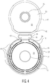
FIG. 4 is a top plan view of the cap ofFIG. 1 , in an opened position; -
FIG. 5 is a bottom plan view of the cap ofFIG. 1 , in an opened position; -
FIG. 6 is a perspective view of an exemplary stopper for use with the cap of the invention; -
FIG. 7 is a cross section taken along line 7-7 ofFIG. 1 ; -
FIG. 8 is a partial cross section taken along line 8-8 ofFIG. 3 ; -
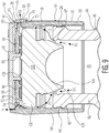
FIG. 9 is a cross section such as that ofFIG. 8 , with the cap in the lyophilisation position; -
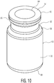
FIG. 10 is a perspective view of an exemplary vial for use with the cap of the invention; -
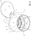
FIG. 11 is a bottom perspective view of the vial cap ofFIG. 1 , in an opened position; and -
FIG. 12 is a bottom perspective view of the vial cap ofFIG. 1 , in an opened position, with the hinge broken. - Certain terminology is used in the foregoing description for convenience and is not intended to be limiting. Words such as "front," "back," "top," and "bottom" designate directions in the drawings to which reference is made. This terminology includes the words specifically noted above, derivatives thereof, and words of similar import. Additionally, the words "a" and "one" are defined as including one or more of the referenced item unless specifically noted. The phrase "at least one of" followed by a list of two or more items, such as "A, B or C," means any individual one of A, B or C, as well as any combination thereof.
-
FIGS. 1-5 and7-9 show an embodiment of aparenteral vial cap 10 according to the invention. As shown, thecap 10 includes amain body 20 and acover 50. Themain body 20 is formed as a generallytubular wall 22 configured to surround theneck 82 of aparenteral vial 80. Thecover 50 fits on top of themain body 20 to cover the opening when thecap 10 is in the closed position, as shown inFIGS. 1-3 and6-9 . Thecap 10 is configured to accommodate astopper 100, which is configured to sealingly fit within and close anopening 84 formed at the top of thevial neck 82 and leading to theinterior 86. Thecap 10 and thestopper 100 fit together to form an integral unit, which can be used to cap thevial 80. Thecap 10 is configured to move with respect to thevial 80 between a partially engaged position that permits gas flow out from the vial interior, and a fully engaged position in which thestopper 100 sealingly engages theopening 84. - Referring to
FIG. 10 , anexemplary vial 80 for use with the invention is shown. As shown, thevial 80 includes abase wall 88 and a substantiallytubular side wall 90 extending upwardly from thebase wall 88, thebase wall 88 andside wall 90 together defining theinterior 86 of thevial 80. A radially inwardly extendingshoulder 98 is formed at an upper portion of theside wall 90 and joins theside wall 90 with theneck 82. Arim 92 is formed at an upper edge of theneck 82 as a section of increased radial thickness with respect to theneck 82. Therim 92 includes atop surface 94 and defines the opening 84 of thevial 80. An outerannular groove 96 is formed on an outer surface of therim 90 and is configured to facilitate attachment of thecap 10, as described in detail below. An innerannular groove 97 is formed on an inner surface of theneck 82, near theopening 84, to facilitate attachment of thestopper 100, as described in detail below. - Now referring to
FIGS. 6 ,8 and9 , anexemplary vial stopper 100 for use with the invention is shown in detail. As shown, thestopper 100 includes a substantially horizontally extendingtop wall 102 and aplug 104 extending downward therefrom. Thetop wall 102 is configured to completely or substantially completely cover thevial rim 92 and opening 84 when seated thereon. Accordingly, thetop wall 102 has a diameter substantially equal to the outer diameter of therim 92. Thetop wall 102 could alternatively have an outer diameter greater than that of therim 92, or less than that of therim 92, but greater than the inner diameter of the opening 84, such that the opening 84 is in any event covered by thetop wall 102 when thestopper 100 is seated thereon. The outer edges of thetop wall 102 and therim 92 may be substantially radially aligned, such as in the illustrated embodiment in which the outer diameter of therim 92 is slightly greater than that of the top wall. - The
plug 104 extends downward from a bottom surface of thetop wall 102 and has an outer diameter equal to or slightly greater than the inner diameter of theopening 84. In use, theplug 104 extends into theopening 84 and forms an interference fit therewith to seal thevial 80. Theplug 104 may include a dome shapedindentation 106 at the bottom thereof, to facilitate deformation of theplug 104 during insertion into theopening 84 in order to achieve an optimum fit and seal. A firstcircular ridge 108 is formed on the top surface of thetop wall 102, for engagement of thestopper 100 with thecap 10, as described in detail below. A secondcircular ridge 110 is formed on an outer surface of theplug 104 to facilitate engagement with thevial opening 84, as described in detail below. - With reference to
FIGS. 1-5 , and7-9 , thecap 10 will now be described in detail. Thecap 10 comprises amain body 20 and acover 50. Themain body 20 is formed as a substantiallytubular wall 22. Thetubular wall 22 is configured to surround thevial rim 92 and stoppertop wall 102 when thecap 10 is affixed on thevial 10. As shown, the inner diameter of thetubular wall 22 is slightly greater than the outer diameters of therim 92 andtop wall 102. Thetubular wall 22 has a sufficient length in the axial direction to permit extension from theshoulder 98 to a point above thetop wall 102 of thestopper 100, when thecap 10 is in the fully closed position on thevial 80, as shown inFIG. 8 . A plurality of radially inwardly extendingprotrusions 26 are formed on the inner surface of thetubular wall 22. A radially inwardly extending annular ridge is 28 further formed on the inner surface of thetubular wall 22, at an axial location above theprotrusions 26. - Referring now to
FIGS. 2 ,4 and5 , atop wall 30 extends across an upper portion of thetubular wall 22. Thetop wall 30 extends in the horizontal or radial direction of thecap 10, near the top edge of thetubular wall 22. A central,circular aperture 32 is formed in the top wall. Additionally, achannel 34 extends circumferentially near the edge of thetop wall 30, about the entire circumference thereof. Avalley 40, formed as an extension of thechannel 34, extends radially outward therefrom, from an outer edge of thechannel 34 to an outer edge of thetop wall 30 radially aligned with and adjacent to thehinge 36. Thevalley 40 terminates where thetop wall 30 meets thetubular wall 22 at a radially inwardlyindented region 70 thereof. Theindented region 70 is located on an outer surface of thetubular wall 22, radially aligned with thehinge 36, and joins with an axially upper edge of thetubular wall 22. Agap 62 is formed between an inner surface of thehinge tab 38 and theindented region 70 of thetubular wall 22. - A plurality of
openings 42 are formed in thetop wall 30 within thechannel 34.Depressions 44 in the thickness of thetubular wall 22 are formed on the inner surface thereof, in axial alignment with the openings, as shown inFIG. 11 . One or moreannular projections top wall 30, radially located between theaperture 32 and thechannel 34. In the illustrated embodiment, two projections are formed, including a radiallyinner projection 46 and a radiallyouter projection 48, though fewer or more projections could be formed as well. Theprojections stopper 100 when moving thecap 10 from the partially engaged position to the fully engaged position, as described below. - The
hinge 36 is formed as atab 38 that pivotally attaches an edge of thecover 50 to an upper portion of thetubular wall 22. Thehinge 36 is a double hinge, such that it includes a first pivot axis P1 where it attaches to thetubular wall 22 and a second pivot axis P2 where it attaches to cover 50. Thehinge 36 is preferably of the "living hinge" type, i.e., formed integrally with the remainder of thecap 10, with the pivot axes P1, P2 being formed as sections of material sufficiently thin to as to permit bending. Thehinge 36 permits thecover 50 to rotate with respect to themain body 20 between an opened position, for example as shown inFIG. 2 , and a closed position, for example as shown inFIG. 1 . - The cover includes a
cover base 52, which is formed as a round wall configured to cover thetop wall 30 of themain body 20 when in the closed position. Anouter flange 54 extends downward from a bottom surface of thebase 52 and around the entire outer perimeter of thebase 52, and is configured to be received by thechannel 34, when thecover 50 is in the closed position.Outer flange 54 does not sit perfectly withinchannel 34; rather, asmall gap 58 is formed therebetween. Aninner ring 56 also projects downward from the bottom surface of thebase 52, at a substantially central location thereof, and is configured to fit within theaperture 32 when the cover is in the closed position. - The
cap 10, when affixed to thevial 80, moves between a partially engaged, or lyophilization position, as shown inFIG. 9 , and a fully engaged position, as shown inFIG. 8 . Thecap 10 in the fully engaged position is located axially below the partially engaged position. Furthermore, thecover 50 moves between an initial opened position, as shown inFIG. 2 , a closed position, as shown inFIG. 1 , and a final opened position, as shown inFIG. 12 , in which thehinge 36 has been broken. - Referring first to
FIG. 9 , the partially engaged position will be described in detail. As shown, when thecap 10 is in the partially engaged position, thecover 50 is in the closed position. Accordingly, thecover 50 sits atop themain body 20 with outer edge of the base 52 resting on the upper edges of thetubular wall 22. Thestopper 100 is positioned within thetubular wall 22 and beneath thetop wall 30. Theaperture 32 andopenings 42 are covered by thecover 50.Flange 54 sits withinchannel 34. Preferably,flange 54 andchannel 34 are frictionally engaged, and may form an interference fit. Engagement of theflange 54 andchannel 34 helps to retain thecover 50 in place on thetubular wall 22. - Still referring to
FIG. 9 , ring 56 projects downward from the bottom surface ofcover base 52 and fits withinaperture 32 of top wall. Preferably,ring 56 andaperture 32 are frictionally engaged, and may form an interference fit. Engagement of thering 56 andaperture 32 helps retain thecover 50 on themain body 20, keeping thecover 50 in the closed position. -
Ring 56 continues to project downwardpast aperture 32, and reaches thetop wall 102 ofstopper 100, where it receives thefirst ridge 108. Preferably, thefirst ridge 108 andring 56 are frictionally engaged, and may form an interference fit. Engagement of thefirst ridge 108 andring 56 helps retain thestopper 100 in place beneath thetop wall 30 of the capmain body 20. - Still referring to
FIG. 9 ,protrusions 26 of thetubular wall 22 are received within the outerannular groove 96 ofvial rim 92. Preferably,protrusions 26 and outerannular groove 96 are frictionally engaged, and may form an interference fit. Engagement of theprotrusions 26 and outerannular groove 96 help retain thecap 10 in place on thevial 80 in the partially engaged, or lyophilization position. Preferably, the engagement of theprotrusions 26 and theridge 28 is strong enough so as to prevent inadvertent disengagement, for example as could be caused by bumping thecap 10, but not so strong as to prevent disengagement to move thecap 10 downward on thevial 80, into the fully engaged position, as described below. - When the
cap 10 is in the partially engaged position on thevial 10, theopening 84 of thevial 10 is substantially covered, to prevent foreign objects from entering. Additionally, thestopper 100, while not yet directly engaged with thevial 10, is positioned to be moved directly downward to be positioned on thevial 10. This position permits gas flow out from thevial interior 86. As shown inFIG. 9 , a plurality of flow paths F are formed from the interior 86 to the exterior of thevial 10, to allow for escape of moisture vapor during lyophilization. As shown inFIG. 9 , several of the flow paths F1 begin at thevial interior 86 and travel between thevial rim 92 andstopper plug 104, outward then upward between thetubular wall 22 and outer edge of stoppertop wall 102 withindepressions 44, inward between thestopper top wall 102 and cap basetop wall 30, upwards throughopenings 42, then outwards throughgap 58 formed betweenflange 54 andchannel 34. Additional flow paths F2 begin at thevial interior 86 and travel between thevial rim 92 andstopper plug 104, outward then upward between thetubular wall 22 and cap basetop wall 102 withindepressions 44, inward between thestopper top wall 102 and cap basetop wall 30, upwards throughopenings 42, throughchannel 34 and then throughvalley 40 and outward throughgap 62. - After lyophilization, the
cap 10 is moved downwards on the vial, to the fully engaged position, as shown inFIG. 8 . In this position, thestopper 100 and thecap 10 remain in the same position with respect to each other and retain their engagements with each other. Accordingly, the above-described engagements between thering 56 andaperture 32 as well as thering 56 andridge 108, remain in place. Thecap 10 andstopper 100 together move downward as a unit with respect to thevial 80 to move the assembly into the fully engaged position. - As shown, in the fully engaged position, the
ridge 28 oftubular wall 22 is now received by outerannular groove 96 of vial rim. Preferably, theridge 28 and outerannular groove 96 are frictionally engaged, and may form an interference fit. Engagement of theridge 28 and outerannular groove 96 helps retain thecap 10 in place on thevial 80 in the fully engaged position. Preferably, the engagement of theridge 28 andgroove 96 is sufficient to prevent disengagement that would allow movement of thecap 10 with respect to thevial 80, for example removal of thecap 10 from thevial 80 using manual force. It is for this reason that a completeannular ridge 28 is provided on the inner surface of the tubular wall for this purpose, in contrast to theprotrusions 26 provided for engagement with the outerannular groove 96 when in the partially engaged position, which results in a weaker engagement, so as to permit moving thecap 10 from the partially engaged position to the fully engaged position. - Also in the fully engaged position, the
plug 104 is received within thevial opening 84. Preferably, theplug 104 and theopening 84 are frictionally engaged and may form an interference fit. Thesecond ridge 110 formed on the outer surface of thestopper plug 104 is received by the innerannular groove 97. Preferably, thesecond ridge 110 and the innerannular groove 97 are frictionally engaged, and may form an interference fit. Engagement between thesecond ridge 110 and innerannular groove 97 helps retain theplug 104 within theopening 84 and inturn cap 10 in place on thevial 80 in the fully engaged position. - In the fully engaged position, flow path F has been closed off by closing the spaces between the
stopper 100 andvial rim 92. Thestopper 100 and vial rim 92 preferably form a sealed engagement, to prevent entry of foreign objects, as well as to prevent entry and further exit of any liquid or gas matter. The assembly, includingcap 10,vial 80, andstopper 100 is suitable for transport and distribution to consumers at this point. - The
hinge 36 may serve as a tamper evident feature of thecap 10. When thevial 80 andcap 10 assembly reaches a consumer, thecover 50 is to be removed from thecap 10, giving the user access to theaperture 32 and thestopper top wall 102 located below. Atab 60 is formed as an extension of thecover base 52. Thetab 60 protrudes slightly outward from thecover base 52, and may be located over theindented region 70 on the outer surface oftubular wall 22, such that a user can easily accesstab 60 as a source of leverage to permit removal of thecover 50 fromcap base 50.Hinge 36 connectstab 50 with astep 72 formed at the bottom ofindented region 70. In order to force thecover 50 off ofmain body 20 by way of tab, hinge 36 must be broken, which can be achieved easily at the fold formed by first pivot axis P1. Thehinge 36 may optionally include aperforation 40 at the first pivot point P1, to facilitate breaking of the hinge in this manner. Abroken hinge 36 alerts the consumer that thecover 50 has been detached frommain body 20, serving as a tamper evident mechanism.FIG. 12 shows the cap in the final opened position, with thehinge 36 broken at the first pivot axis P1 to alert the consumer that thecover 50 has been detached from themain body 20. - Once the
cover 50 is removed frommain body 20 andtop wall 102 of stopper is accessible, the consumer can insert a syringe throughtop wall 102 and retrieve a dose of the medication contained within thevial 80. - The components of the assembly described above can each be made of any suitable material known in the art. Exemplary materials for forming the vial include glass and polymeric materials, such as cyclic olefin polymer and cyclic olefin copolymer. Exemplary materials for forming the cap include polymeric materials such as polypropylene. Exemplary materials for forming the stopper include elastomeric materials.
- While the preferred embodiments of the invention have been described in detail above, the invention is not limited to the specific embodiments described, which should be considered as merely exemplary.
Claims (13)
- A parenteral vial, stopper and cap assembly, comprising:a vial (80) having a body defining an interior (86), and an opening (84) leading to the interior;a stopper (100) configured to sealingly engage the opening; anda cap (10) configured to cover the opening and the stopper;wherein the stopper and the cap fit together to form an integral unit;the cap moves with respect to the vial between a partially engaged position that permits gas flow out from the vial interior, and a fully engaged position in which the stopper sealingly engages the opening;the cap includes a main body (20) formed as a tubular wall (22), and a cover (50) that fits over the tubular wall, wherein the vial comprises a neck (82) and a rim (92) at an upper edge of the neck, and the tubular wall surrounds the neck and the rim when the cap is in the partially engaged position and the fully engaged position;the tubular wall comprises a plurality of radially inwardly extending protrusions (26) on an inner surface thereof;the rim comprises an outer annular groove (96) on an outer surface thereof;the protrusions are received within the outer annular groove when the assembly is in the partially engaged position;the tubular wall comprises a radially inwardly extending annular ridge (28) on an inner surface thereof;the annular ridge is received within the outer annular groove when the assembly is in the fully engaged position; andthe protrusions are located below the annular ridge in an axial direction of the assembly.
- The assembly of claim 1, wherein the rim defines the opening (84) and wherein the cap (10) is configured to cover the rim (92) when in the partially engaged position and the engaged position.
- The assembly of claim 1, wherein the cap (10) accommodates and retains the stopper (100), wherein the stopper comprises a top wall (102) and a plug (104) extending downward from a bottom surface of the top wall, and the top wall sits beneath the cover (150) when the stopper is retained by the cap.
- The assembly of any one of claims 1-3, wherein the cap (10) further comprises a top wall (30) extending in a radial direction of the cap near a top edge of the tubular wall (22), wherein the stopper (100) is located below the top wall when the assembly is in the partially engaged position and the fully engaged position,
wherein optionally the top wall defines a central aperture (32) that exposes a top surface of the stopper, wherein the top wall comprises a ring (56) that extends downwardly from a bottom surface thereof, and the ring is received within the aperture when the cap is in the engaged position and the partially engaged position, and
wherein the top wall is optionally configured to engage the cover when the cap is in the partially engaged position and the fully engaged position. - The assembly of claim 4, wherein the top wall (30) defines a channel (34) and the cover (50) comprises a downwardly extending flange (54) that is received within the channel when the cover is in the partially engaged position and the fully engaged position.
- The assembly of claim 4 or claim 5, wherein the top wall (30) defines a plurality of openings (42) that permit gas flow therethrough, to permit gas flow out from the vial interior (86) when the cap (10) is in the partially engaged position, wherein the openings form part of a plurality of flow paths (F1, F2) through which gas flows out from the vial interior when the cap is in the partially engaged position.
- The assembly of claim 6, wherein:the top wall (30) defines a channel (34);the cover (50) comprises a downwardly extending flange (54) that is received within the channel when the cover is in the partially engaged position and the fully engaged position; andthe openings (42) are formed within the channel.
- The assembly of any one of claims 5-7, wherein a gap (58) is formed between the flange (54) and the channel (34), wherein the gap permits gas flow therethrough so as to permit gas flow out from the vial interior (86) when the cap (10) is in the partially engaged position.
- The assembly of any one of claims 5-8, wherein the top wall (30) further defines a valley (40) extending from the channel (34) to an outer surface of the tubular wall (22),
wherein the valley optionally permits gas flow therethrough, so as to permit gas flow out from the vial interior (86) when the cap (10) is in the partially engaged position, and
wherein the valley is optionally radially aligned with a hinge (36) that attaches the main body (20) and the cover (50). - The assembly of any one of claims 4-9, wherein the top wall (30) further comprises at least one annular projection (46, 48) extending downward from a bottom surface thereof, the at least one annular projection configured to contact the stopper (100) when the cap (10) is in the partially engaged position and the fully engaged position, wherein the at least one annular projection is configured to exert an even force on the stopper when the cap is moved from the partially engaged position to the fully engaged position,
wherein optionally the at least one annular projection comprises two annular projections including a radially inner annular projection (46) and a radially outer annular projection (48). - The assembly of any one of claims 1-10, further comprising a hinge (36) that connects the cover (50) to the main body (20), wherein the hinge is formed integrally with the main body and the cover,
wherein optionally the cover affixes to the main body when the cap (10) is in the partially engaged position and the fully engaged position, such that the hinge must be broken in order to detach the cover from the main body, and
wherein the hinge optionally comprises a perforation (40) to facilitate breaking of the hinge. - The assembly of any previous claim, wherein the partially engaged position is axially higher with respect to the vial (80) than the fully engaged position.
- The assembly of any previous claim, wherein the vial is formed of glass, or a polymeric material, such as a cyclic olefin polymer or a cyclic olefin copolymer; and/or
the cap (10) is formed of a polymeric material, such as polypropylene; and/or
the stopper (100) is formed of an elastomeric material.
Priority Applications (1)
| Application Number | Priority Date | Filing Date | Title |
|---|---|---|---|
| EP17199624.2A EP3295917A1 (en) | 2013-07-03 | 2014-06-24 | Parenteral vial cap |
Applications Claiming Priority (3)
| Application Number | Priority Date | Filing Date | Title |
|---|---|---|---|
| US201361842478P | 2013-07-03 | 2013-07-03 | |
| US201361862204P | 2013-08-05 | 2013-08-05 | |
| PCT/US2014/043810 WO2015002768A1 (en) | 2013-07-03 | 2014-06-24 | Parenteral vial cap |
Related Child Applications (2)
| Application Number | Title | Priority Date | Filing Date |
|---|---|---|---|
| EP17199624.2A Division-Into EP3295917A1 (en) | 2013-07-03 | 2014-06-24 | Parenteral vial cap |
| EP17199624.2A Division EP3295917A1 (en) | 2013-07-03 | 2014-06-24 | Parenteral vial cap |
Publications (2)
| Publication Number | Publication Date |
|---|---|
| EP3016628A1 EP3016628A1 (en) | 2016-05-11 |
| EP3016628B1 true EP3016628B1 (en) | 2018-03-28 |
Family
ID=51230172
Family Applications (2)
| Application Number | Title | Priority Date | Filing Date |
|---|---|---|---|
| EP14744670.2A Active EP3016628B1 (en) | 2013-07-03 | 2014-06-24 | Parenteral vial cap |
| EP17199624.2A Withdrawn EP3295917A1 (en) | 2013-07-03 | 2014-06-24 | Parenteral vial cap |
Family Applications After (1)
| Application Number | Title | Priority Date | Filing Date |
|---|---|---|---|
| EP17199624.2A Withdrawn EP3295917A1 (en) | 2013-07-03 | 2014-06-24 | Parenteral vial cap |
Country Status (3)
| Country | Link |
|---|---|
| US (1) | US10327986B2 (en) |
| EP (2) | EP3016628B1 (en) |
| WO (1) | WO2015002768A1 (en) |
Families Citing this family (12)
| Publication number | Priority date | Publication date | Assignee | Title |
|---|---|---|---|---|
| US9567143B2 (en) | 2013-12-19 | 2017-02-14 | West Pharmaceutical Services, Inc. | Tamper evident closure for containers |
| WO2015193773A1 (en) * | 2014-06-20 | 2015-12-23 | Lameplast S.P.A. | Strips of vials for fluid products, particularly for medical, pharmaceutical, cosmetic, food products or the like |
| WO2018035047A1 (en) | 2016-08-15 | 2018-02-22 | Genentech, Inc. | Vial assembly with luer fitting |
| KR102618377B1 (en) | 2017-12-07 | 2023-12-27 | 후지모리 고교 가부시키가이샤 | Bags with attached ports and bags with attached caps |
| KR102727299B1 (en) | 2019-12-12 | 2024-11-08 | 노파르티스 아게 | Injection device and injection solution delivery system |
| US12104990B2 (en) * | 2019-12-16 | 2024-10-01 | Shane Park | Apparatus for collecting and storing fluid samples from vehicles and machinery |
| JP7437760B2 (en) | 2020-06-18 | 2024-02-26 | 三笠産業株式会社 | cap |
| IT202100003191A1 (en) | 2021-02-12 | 2022-08-12 | Bisio Progetti Spa | RUBBER SEALING ELEMENT FOR A PLASTIC CLOSURE FOR INJECTIVE DRUGS |
| IT202100003188A1 (en) | 2021-02-12 | 2022-08-12 | Bisio Progetti Spa | BOTTLE FOR A CONTAINER FOR PHARMACEUTICALS FOR INJECTIVE INJURY |
| IT202100003182A1 (en) | 2021-02-12 | 2022-08-12 | Bisio Progetti Spa | PLASTIC CLOSURE FOR A CONTAINER FOR INJURING PHARMACEUTICAL PRODUCTS |
| US12065295B2 (en) * | 2021-08-19 | 2024-08-20 | Closure Systems International Inc. | One-piece closure |
| US12534276B2 (en) | 2024-03-12 | 2026-01-27 | Closure Systems International Inc. | Closure assembly and package with closure assembly |
Family Cites Families (24)
| Publication number | Priority date | Publication date | Assignee | Title |
|---|---|---|---|---|
| FI66807C (en) * | 1977-05-09 | 1984-12-10 | Asicomo As | CAPSULE FOR BEHAOLLARLOCK AND FOAR FARANDE FOER TILLVERKNING AV DETSAMMA |
| US4244478A (en) * | 1979-06-27 | 1981-01-13 | Mpl, Inc. | Closure assembly for unit dose vial |
| KR900017870A (en) * | 1989-05-05 | 1990-12-20 | 에이취 코오트 도우티 쥬니어 | Stackable Lids Containers |
| DE4127650C1 (en) | 1991-08-21 | 1993-02-25 | Arzneimittel Gmbh Apotheker Vetter & Co Ravensburg, 7980 Ravensburg, De | |
| US5344036A (en) * | 1992-06-04 | 1994-09-06 | Akzo N.V. | Container system |
| DE4314923C2 (en) * | 1993-05-06 | 1998-08-27 | West Company Deutschland Gmbh | Cap for closing a bottle |
| US5718348A (en) | 1996-09-12 | 1998-02-17 | Comar, Inc. | Overcap assembly for gear finish vial |
| US5901866A (en) * | 1998-02-13 | 1999-05-11 | Comar Inc. | Break away overcap |
| US5819964A (en) | 1996-09-27 | 1998-10-13 | Becton Dickinson And Company | Lyophilization closure assembly for a medicament container for use during a lyophilization process |
| US6910623B2 (en) * | 1999-02-13 | 2005-06-28 | Smurfit-Stone Container Enterprises, Inc. | Paperboard can with an integrated lid having a hinge on the lid |
| RU2379217C2 (en) * | 2002-09-03 | 2010-01-20 | Медикал Инстилл Текнолоджис, Инк. | Vial assembly to store substance (versions), device assembly containing said vial and method for filling vial |
| WO2004096113A2 (en) * | 2003-04-28 | 2004-11-11 | Medical Instill Technologies, Inc. | Container with valve assembly for filling and dispensing substances, and apparatus and method for filling |
| WO2005000703A2 (en) * | 2003-06-23 | 2005-01-06 | Helvoet Pharma Belgium N.V. | Closure for lyophilizing |
| GB0510057D0 (en) * | 2005-05-17 | 2005-06-22 | Glaxosmithkline Biolog Sa | Novel device |
| FR2912384B1 (en) * | 2007-02-09 | 2009-04-10 | Biocorp Rech Et Dev Sa | CLOSURE DEVICE FOR A CONTAINER, CONTAINER EQUIPPED WITH SUCH A DEVICE AND METHOD FOR CLOSING A LOT OF SUCH A CONTAINER |
| US20090001042A1 (en) * | 2007-06-26 | 2009-01-01 | Robert Sever | Container-closure system for use in lyophilization applications |
| JP5231794B2 (en) * | 2007-12-10 | 2013-07-10 | 株式会社大協精工 | Plastic cap for vials |
| DE102008051351A1 (en) | 2008-10-10 | 2010-04-15 | Friedrich Sanner Gmbh & Co. Kg | Closure for pressing and locking with a container |
| EP2383199B1 (en) * | 2010-04-30 | 2013-06-12 | Sumitomo Rubber Industries, Ltd. | Closure device for a container, and seal member for the device |
| DE102010016866B4 (en) * | 2010-05-10 | 2018-06-21 | Helvoet Pharma Belgium N.V. | Closure for a container and method for carrying out a freeze-drying method |
| JP6438767B2 (en) * | 2011-09-29 | 2018-12-19 | ジーイー・ヘルスケア・アクスイェ・セルスカプ | package |
| FR2986782B1 (en) * | 2012-02-13 | 2014-03-07 | Raymond A & Cie | PLUG LOCKING DEVICE ON FLANGE CONTAINER, PLUG-IN CLOSURE FLANGE CONTAINER PROVIDED WITH SUCH LATCHING DEVICE |
| FR2987825B1 (en) * | 2012-03-09 | 2015-06-05 | Biocorp Rech Et Dev | CLOSURE DEVICE AND CONTAINER EQUIPPED WITH SUCH A DEVICE |
| US9555940B2 (en) * | 2013-09-02 | 2017-01-31 | Taisei Kako Co., Ltd. | Cap for vial |
-
2014
- 2014-06-24 EP EP14744670.2A patent/EP3016628B1/en active Active
- 2014-06-24 US US14/902,604 patent/US10327986B2/en active Active
- 2014-06-24 EP EP17199624.2A patent/EP3295917A1/en not_active Withdrawn
- 2014-06-24 WO PCT/US2014/043810 patent/WO2015002768A1/en not_active Ceased
Also Published As
| Publication number | Publication date |
|---|---|
| WO2015002768A1 (en) | 2015-01-08 |
| US20160184182A1 (en) | 2016-06-30 |
| US10327986B2 (en) | 2019-06-25 |
| EP3016628A1 (en) | 2016-05-11 |
| EP3295917A1 (en) | 2018-03-21 |
Similar Documents
| Publication | Publication Date | Title |
|---|---|---|
| US10327986B2 (en) | Parenteral vial cap | |
| EP2915585B1 (en) | Tamper-evident closure assembly having two tamper-evidencing members, and related methods | |
| US11299330B2 (en) | Container with outer cap for a child-resistant closure | |
| US6168035B1 (en) | Child-resistant threaded closure | |
| EP3081505B1 (en) | Tamper-evident closure and assembly of tamper-evident closure and container assembly | |
| US11034066B2 (en) | Apparatus, system and method of providing a safety container | |
| JP5778784B2 (en) | Container dispensing cap | |
| CN218705357U (en) | Tamper-evident plastic closure for a vial | |
| JP3780009B2 (en) | Lid with cap to prevent unsealing for injection bottle and infusion bottle | |
| US20210276769A1 (en) | Child-Resistant Closure | |
| MX2008011526A (en) | Closure arrangement for containers. | |
| US10011405B2 (en) | Child resistant safety cap with ring, lock and lever | |
| US20250017819A1 (en) | Medicament container | |
| MX2014002368A (en) | Tamper-evident closure. | |
| CN101460372A (en) | Bottle for fluid products, in particular pharmaceutical, medical or cosmetic products | |
| CN100564179C (en) | Child-resistant flip-top container assembly and flip-top closure | |
| US5397008A (en) | Child resistant cap and safety collar ring | |
| JP6013325B2 (en) | Cap of container and method for performing freeze-drying method | |
| US9718590B2 (en) | Child resistant cap with safety ring and ring gap lock | |
| US20130048638A1 (en) | Self-Piercing Closure with a Self-Closing Valve | |
| US20160257450A1 (en) | Container with twist closure | |
| US20240308738A1 (en) | Rubber sealing element for a plastic closing device for parenterally administrable drugs | |
| JP2013129430A (en) | Pilfer-proof cap | |
| CA2042551A1 (en) | Closure cap for infusion or transfusion bottles | |
| KR200398918Y1 (en) | Safety plug |
Legal Events
| Date | Code | Title | Description |
|---|---|---|---|
| PUAI | Public reference made under article 153(3) epc to a published international application that has entered the european phase |
Free format text: ORIGINAL CODE: 0009012 |
|
| 17P | Request for examination filed |
Effective date: 20160128 |
|
| AK | Designated contracting states |
Kind code of ref document: A1 Designated state(s): AL AT BE BG CH CY CZ DE DK EE ES FI FR GB GR HR HU IE IS IT LI LT LU LV MC MK MT NL NO PL PT RO RS SE SI SK SM TR |
|
| AX | Request for extension of the european patent |
Extension state: BA ME |
|
| DAX | Request for extension of the european patent (deleted) | ||
| STAA | Information on the status of an ep patent application or granted ep patent |
Free format text: STATUS: EXAMINATION IS IN PROGRESS |
|
| 17Q | First examination report despatched |
Effective date: 20170213 |
|
| GRAP | Despatch of communication of intention to grant a patent |
Free format text: ORIGINAL CODE: EPIDOSNIGR1 |
|
| STAA | Information on the status of an ep patent application or granted ep patent |
Free format text: STATUS: GRANT OF PATENT IS INTENDED |
|
| INTG | Intention to grant announced |
Effective date: 20171128 |
|
| GRAS | Grant fee paid |
Free format text: ORIGINAL CODE: EPIDOSNIGR3 |
|
| GRAA | (expected) grant |
Free format text: ORIGINAL CODE: 0009210 |
|
| STAA | Information on the status of an ep patent application or granted ep patent |
Free format text: STATUS: THE PATENT HAS BEEN GRANTED |
|
| AK | Designated contracting states |
Kind code of ref document: B1 Designated state(s): AL AT BE BG CH CY CZ DE DK EE ES FI FR GB GR HR HU IE IS IT LI LT LU LV MC MK MT NL NO PL PT RO RS SE SI SK SM TR |
|
| REG | Reference to a national code |
Ref country code: GB Ref legal event code: FG4D |
|
| REG | Reference to a national code |
Ref country code: CH Ref legal event code: EP |
|
| REG | Reference to a national code |
Ref country code: AT Ref legal event code: REF Ref document number: 982737 Country of ref document: AT Kind code of ref document: T Effective date: 20180415 |
|
| REG | Reference to a national code |
Ref country code: IE Ref legal event code: FG4D |
|
| REG | Reference to a national code |
Ref country code: DE Ref legal event code: R096 Ref document number: 602014023003 Country of ref document: DE |
|
| REG | Reference to a national code |
Ref country code: FR Ref legal event code: PLFP Year of fee payment: 5 |
|
| PG25 | Lapsed in a contracting state [announced via postgrant information from national office to epo] |
Ref country code: HR Free format text: LAPSE BECAUSE OF FAILURE TO SUBMIT A TRANSLATION OF THE DESCRIPTION OR TO PAY THE FEE WITHIN THE PRESCRIBED TIME-LIMIT Effective date: 20180328 Ref country code: NO Free format text: LAPSE BECAUSE OF FAILURE TO SUBMIT A TRANSLATION OF THE DESCRIPTION OR TO PAY THE FEE WITHIN THE PRESCRIBED TIME-LIMIT Effective date: 20180628 Ref country code: FI Free format text: LAPSE BECAUSE OF FAILURE TO SUBMIT A TRANSLATION OF THE DESCRIPTION OR TO PAY THE FEE WITHIN THE PRESCRIBED TIME-LIMIT Effective date: 20180328 Ref country code: LT Free format text: LAPSE BECAUSE OF FAILURE TO SUBMIT A TRANSLATION OF THE DESCRIPTION OR TO PAY THE FEE WITHIN THE PRESCRIBED TIME-LIMIT Effective date: 20180328 |
|
| REG | Reference to a national code |
Ref country code: NL Ref legal event code: MP Effective date: 20180328 |
|
| REG | Reference to a national code |
Ref country code: LT Ref legal event code: MG4D |
|
| PG25 | Lapsed in a contracting state [announced via postgrant information from national office to epo] |
Ref country code: LV Free format text: LAPSE BECAUSE OF FAILURE TO SUBMIT A TRANSLATION OF THE DESCRIPTION OR TO PAY THE FEE WITHIN THE PRESCRIBED TIME-LIMIT Effective date: 20180328 Ref country code: SE Free format text: LAPSE BECAUSE OF FAILURE TO SUBMIT A TRANSLATION OF THE DESCRIPTION OR TO PAY THE FEE WITHIN THE PRESCRIBED TIME-LIMIT Effective date: 20180328 Ref country code: RS Free format text: LAPSE BECAUSE OF FAILURE TO SUBMIT A TRANSLATION OF THE DESCRIPTION OR TO PAY THE FEE WITHIN THE PRESCRIBED TIME-LIMIT Effective date: 20180328 Ref country code: BG Free format text: LAPSE BECAUSE OF FAILURE TO SUBMIT A TRANSLATION OF THE DESCRIPTION OR TO PAY THE FEE WITHIN THE PRESCRIBED TIME-LIMIT Effective date: 20180628 Ref country code: GR Free format text: LAPSE BECAUSE OF FAILURE TO SUBMIT A TRANSLATION OF THE DESCRIPTION OR TO PAY THE FEE WITHIN THE PRESCRIBED TIME-LIMIT Effective date: 20180629 |
|
| PG25 | Lapsed in a contracting state [announced via postgrant information from national office to epo] |
Ref country code: AL Free format text: LAPSE BECAUSE OF FAILURE TO SUBMIT A TRANSLATION OF THE DESCRIPTION OR TO PAY THE FEE WITHIN THE PRESCRIBED TIME-LIMIT Effective date: 20180328 Ref country code: ES Free format text: LAPSE BECAUSE OF FAILURE TO SUBMIT A TRANSLATION OF THE DESCRIPTION OR TO PAY THE FEE WITHIN THE PRESCRIBED TIME-LIMIT Effective date: 20180328 Ref country code: NL Free format text: LAPSE BECAUSE OF FAILURE TO SUBMIT A TRANSLATION OF THE DESCRIPTION OR TO PAY THE FEE WITHIN THE PRESCRIBED TIME-LIMIT Effective date: 20180328 Ref country code: IT Free format text: LAPSE BECAUSE OF FAILURE TO SUBMIT A TRANSLATION OF THE DESCRIPTION OR TO PAY THE FEE WITHIN THE PRESCRIBED TIME-LIMIT Effective date: 20180328 Ref country code: RO Free format text: LAPSE BECAUSE OF FAILURE TO SUBMIT A TRANSLATION OF THE DESCRIPTION OR TO PAY THE FEE WITHIN THE PRESCRIBED TIME-LIMIT Effective date: 20180328 Ref country code: EE Free format text: LAPSE BECAUSE OF FAILURE TO SUBMIT A TRANSLATION OF THE DESCRIPTION OR TO PAY THE FEE WITHIN THE PRESCRIBED TIME-LIMIT Effective date: 20180328 Ref country code: PL Free format text: LAPSE BECAUSE OF FAILURE TO SUBMIT A TRANSLATION OF THE DESCRIPTION OR TO PAY THE FEE WITHIN THE PRESCRIBED TIME-LIMIT Effective date: 20180328 |
|
| PG25 | Lapsed in a contracting state [announced via postgrant information from national office to epo] |
Ref country code: SM Free format text: LAPSE BECAUSE OF FAILURE TO SUBMIT A TRANSLATION OF THE DESCRIPTION OR TO PAY THE FEE WITHIN THE PRESCRIBED TIME-LIMIT Effective date: 20180328 Ref country code: SK Free format text: LAPSE BECAUSE OF FAILURE TO SUBMIT A TRANSLATION OF THE DESCRIPTION OR TO PAY THE FEE WITHIN THE PRESCRIBED TIME-LIMIT Effective date: 20180328 Ref country code: CZ Free format text: LAPSE BECAUSE OF FAILURE TO SUBMIT A TRANSLATION OF THE DESCRIPTION OR TO PAY THE FEE WITHIN THE PRESCRIBED TIME-LIMIT Effective date: 20180328 |
|
| REG | Reference to a national code |
Ref country code: AT Ref legal event code: MK05 Ref document number: 982737 Country of ref document: AT Kind code of ref document: T Effective date: 20180328 |
|
| PG25 | Lapsed in a contracting state [announced via postgrant information from national office to epo] |
Ref country code: PT Free format text: LAPSE BECAUSE OF FAILURE TO SUBMIT A TRANSLATION OF THE DESCRIPTION OR TO PAY THE FEE WITHIN THE PRESCRIBED TIME-LIMIT Effective date: 20180730 |
|
| REG | Reference to a national code |
Ref country code: DE Ref legal event code: R097 Ref document number: 602014023003 Country of ref document: DE |
|
| PG25 | Lapsed in a contracting state [announced via postgrant information from national office to epo] |
Ref country code: AT Free format text: LAPSE BECAUSE OF FAILURE TO SUBMIT A TRANSLATION OF THE DESCRIPTION OR TO PAY THE FEE WITHIN THE PRESCRIBED TIME-LIMIT Effective date: 20180328 Ref country code: DK Free format text: LAPSE BECAUSE OF FAILURE TO SUBMIT A TRANSLATION OF THE DESCRIPTION OR TO PAY THE FEE WITHIN THE PRESCRIBED TIME-LIMIT Effective date: 20180328 |
|
| PLBE | No opposition filed within time limit |
Free format text: ORIGINAL CODE: 0009261 |
|
| STAA | Information on the status of an ep patent application or granted ep patent |
Free format text: STATUS: NO OPPOSITION FILED WITHIN TIME LIMIT |
|
| 26N | No opposition filed |
Effective date: 20190103 |
|
| REG | Reference to a national code |
Ref country code: BE Ref legal event code: MM Effective date: 20180630 |
|
| REG | Reference to a national code |
Ref country code: IE Ref legal event code: MM4A |
|
| PG25 | Lapsed in a contracting state [announced via postgrant information from national office to epo] |
Ref country code: MC Free format text: LAPSE BECAUSE OF FAILURE TO SUBMIT A TRANSLATION OF THE DESCRIPTION OR TO PAY THE FEE WITHIN THE PRESCRIBED TIME-LIMIT Effective date: 20180328 Ref country code: LU Free format text: LAPSE BECAUSE OF NON-PAYMENT OF DUE FEES Effective date: 20180624 |
|
| PG25 | Lapsed in a contracting state [announced via postgrant information from national office to epo] |
Ref country code: IE Free format text: LAPSE BECAUSE OF NON-PAYMENT OF DUE FEES Effective date: 20180624 |
|
| PG25 | Lapsed in a contracting state [announced via postgrant information from national office to epo] |
Ref country code: BE Free format text: LAPSE BECAUSE OF NON-PAYMENT OF DUE FEES Effective date: 20180630 Ref country code: SI Free format text: LAPSE BECAUSE OF FAILURE TO SUBMIT A TRANSLATION OF THE DESCRIPTION OR TO PAY THE FEE WITHIN THE PRESCRIBED TIME-LIMIT Effective date: 20180328 |
|
| PG25 | Lapsed in a contracting state [announced via postgrant information from national office to epo] |
Ref country code: MT Free format text: LAPSE BECAUSE OF NON-PAYMENT OF DUE FEES Effective date: 20180624 |
|
| PG25 | Lapsed in a contracting state [announced via postgrant information from national office to epo] |
Ref country code: TR Free format text: LAPSE BECAUSE OF FAILURE TO SUBMIT A TRANSLATION OF THE DESCRIPTION OR TO PAY THE FEE WITHIN THE PRESCRIBED TIME-LIMIT Effective date: 20180328 |
|
| PG25 | Lapsed in a contracting state [announced via postgrant information from national office to epo] |
Ref country code: MK Free format text: LAPSE BECAUSE OF NON-PAYMENT OF DUE FEES Effective date: 20180328 Ref country code: HU Free format text: LAPSE BECAUSE OF FAILURE TO SUBMIT A TRANSLATION OF THE DESCRIPTION OR TO PAY THE FEE WITHIN THE PRESCRIBED TIME-LIMIT; INVALID AB INITIO Effective date: 20140624 Ref country code: CY Free format text: LAPSE BECAUSE OF FAILURE TO SUBMIT A TRANSLATION OF THE DESCRIPTION OR TO PAY THE FEE WITHIN THE PRESCRIBED TIME-LIMIT Effective date: 20180328 |
|
| PG25 | Lapsed in a contracting state [announced via postgrant information from national office to epo] |
Ref country code: IS Free format text: LAPSE BECAUSE OF FAILURE TO SUBMIT A TRANSLATION OF THE DESCRIPTION OR TO PAY THE FEE WITHIN THE PRESCRIBED TIME-LIMIT Effective date: 20180728 |
|
| PGFP | Annual fee paid to national office [announced via postgrant information from national office to epo] |
Ref country code: GB Payment date: 20220628 Year of fee payment: 9 |
|
| PGFP | Annual fee paid to national office [announced via postgrant information from national office to epo] |
Ref country code: FR Payment date: 20220627 Year of fee payment: 9 |
|
| PGFP | Annual fee paid to national office [announced via postgrant information from national office to epo] |
Ref country code: DE Payment date: 20220629 Year of fee payment: 9 |
|
| PGFP | Annual fee paid to national office [announced via postgrant information from national office to epo] |
Ref country code: CH Payment date: 20220706 Year of fee payment: 9 |
|
| REG | Reference to a national code |
Ref country code: DE Ref legal event code: R119 Ref document number: 602014023003 Country of ref document: DE |
|
| REG | Reference to a national code |
Ref country code: CH Ref legal event code: PL |
|
| GBPC | Gb: european patent ceased through non-payment of renewal fee |
Effective date: 20230624 |
|
| PG25 | Lapsed in a contracting state [announced via postgrant information from national office to epo] |
Ref country code: DE Free format text: LAPSE BECAUSE OF NON-PAYMENT OF DUE FEES Effective date: 20240103 Ref country code: GB Free format text: LAPSE BECAUSE OF NON-PAYMENT OF DUE FEES Effective date: 20230624 Ref country code: CH Free format text: LAPSE BECAUSE OF NON-PAYMENT OF DUE FEES Effective date: 20230630 |
|
| PG25 | Lapsed in a contracting state [announced via postgrant information from national office to epo] |
Ref country code: FR Free format text: LAPSE BECAUSE OF NON-PAYMENT OF DUE FEES Effective date: 20230630 |