EP3016550B1 - A seatback for a passenger seat - Google Patents
A seatback for a passenger seat Download PDFInfo
- Publication number
- EP3016550B1 EP3016550B1 EP14819995.3A EP14819995A EP3016550B1 EP 3016550 B1 EP3016550 B1 EP 3016550B1 EP 14819995 A EP14819995 A EP 14819995A EP 3016550 B1 EP3016550 B1 EP 3016550B1
- Authority
- EP
- European Patent Office
- Prior art keywords
- tray table
- seatback
- base
- cup holder
- Prior art date
- Legal status (The legal status is an assumption and is not a legal conclusion. Google has not performed a legal analysis and makes no representation as to the accuracy of the status listed.)
- Active
Links
Images





Classifications
-
- B—PERFORMING OPERATIONS; TRANSPORTING
- B60—VEHICLES IN GENERAL
- B60N—SEATS SPECIALLY ADAPTED FOR VEHICLES; VEHICLE PASSENGER ACCOMMODATION NOT OTHERWISE PROVIDED FOR
- B60N3/00—Arrangements or adaptations of other passenger fittings, not otherwise provided for
- B60N3/001—Arrangements or adaptations of other passenger fittings, not otherwise provided for of tables or trays
- B60N3/002—Arrangements or adaptations of other passenger fittings, not otherwise provided for of tables or trays of trays
- B60N3/004—Arrangements or adaptations of other passenger fittings, not otherwise provided for of tables or trays of trays of foldable trays mounted on the back-rest
-
- B—PERFORMING OPERATIONS; TRANSPORTING
- B60—VEHICLES IN GENERAL
- B60N—SEATS SPECIALLY ADAPTED FOR VEHICLES; VEHICLE PASSENGER ACCOMMODATION NOT OTHERWISE PROVIDED FOR
- B60N3/00—Arrangements or adaptations of other passenger fittings, not otherwise provided for
- B60N3/10—Arrangements or adaptations of other passenger fittings, not otherwise provided for of receptacles for food or beverages, e.g. refrigerated
- B60N3/102—Arrangements or adaptations of other passenger fittings, not otherwise provided for of receptacles for food or beverages, e.g. refrigerated storable or foldable in a non-use position
-
- B—PERFORMING OPERATIONS; TRANSPORTING
- B60—VEHICLES IN GENERAL
- B60R—VEHICLES, VEHICLE FITTINGS, OR VEHICLE PARTS, NOT OTHERWISE PROVIDED FOR
- B60R11/00—Arrangements for holding or mounting articles, not otherwise provided for
-
- B—PERFORMING OPERATIONS; TRANSPORTING
- B60—VEHICLES IN GENERAL
- B60R—VEHICLES, VEHICLE FITTINGS, OR VEHICLE PARTS, NOT OTHERWISE PROVIDED FOR
- B60R11/00—Arrangements for holding or mounting articles, not otherwise provided for
- B60R11/02—Arrangements for holding or mounting articles, not otherwise provided for for radio sets, television sets, telephones, or the like; Arrangement of controls thereof
-
- B—PERFORMING OPERATIONS; TRANSPORTING
- B60—VEHICLES IN GENERAL
- B60R—VEHICLES, VEHICLE FITTINGS, OR VEHICLE PARTS, NOT OTHERWISE PROVIDED FOR
- B60R7/00—Stowing or holding appliances inside vehicle primarily intended for personal property smaller than suit-cases, e.g. travelling articles, or maps
- B60R7/005—Nets or elastic pockets tensioned against walls or backrests
-
- B—PERFORMING OPERATIONS; TRANSPORTING
- B61—RAILWAYS
- B61D—BODY DETAILS OR KINDS OF RAILWAY VEHICLES
- B61D33/00—Seats
- B61D33/0007—Details; Accessories
-
- B—PERFORMING OPERATIONS; TRANSPORTING
- B63—SHIPS OR OTHER WATERBORNE VESSELS; RELATED EQUIPMENT
- B63B—SHIPS OR OTHER WATERBORNE VESSELS; EQUIPMENT FOR SHIPPING
- B63B29/00—Accommodation for crew or passengers not otherwise provided for
- B63B29/02—Cabins or other living spaces; Construction or arrangement thereof
- B63B29/04—Furniture peculiar to vessels
-
- B—PERFORMING OPERATIONS; TRANSPORTING
- B64—AIRCRAFT; AVIATION; COSMONAUTICS
- B64D—EQUIPMENT FOR FITTING IN OR TO AIRCRAFT; FLIGHT SUITS; PARACHUTES; ARRANGEMENT OR MOUNTING OF POWER PLANTS OR PROPULSION TRANSMISSIONS IN AIRCRAFT
- B64D11/00—Passenger or crew accommodation; Flight-deck installations not otherwise provided for
- B64D11/0015—Arrangements for entertainment or communications, e.g. radio, television
-
- B—PERFORMING OPERATIONS; TRANSPORTING
- B64—AIRCRAFT; AVIATION; COSMONAUTICS
- B64D—EQUIPMENT FOR FITTING IN OR TO AIRCRAFT; FLIGHT SUITS; PARACHUTES; ARRANGEMENT OR MOUNTING OF POWER PLANTS OR PROPULSION TRANSMISSIONS IN AIRCRAFT
- B64D11/00—Passenger or crew accommodation; Flight-deck installations not otherwise provided for
- B64D11/0015—Arrangements for entertainment or communications, e.g. radio, television
- B64D11/00151—Permanently mounted seat back monitors
-
- B—PERFORMING OPERATIONS; TRANSPORTING
- B64—AIRCRAFT; AVIATION; COSMONAUTICS
- B64D—EQUIPMENT FOR FITTING IN OR TO AIRCRAFT; FLIGHT SUITS; PARACHUTES; ARRANGEMENT OR MOUNTING OF POWER PLANTS OR PROPULSION TRANSMISSIONS IN AIRCRAFT
- B64D11/00—Passenger or crew accommodation; Flight-deck installations not otherwise provided for
- B64D11/0015—Arrangements for entertainment or communications, e.g. radio, television
- B64D11/00152—Seat back fixtures for removable monitors, e.g. tablet computers
-
- B—PERFORMING OPERATIONS; TRANSPORTING
- B64—AIRCRAFT; AVIATION; COSMONAUTICS
- B64D—EQUIPMENT FOR FITTING IN OR TO AIRCRAFT; FLIGHT SUITS; PARACHUTES; ARRANGEMENT OR MOUNTING OF POWER PLANTS OR PROPULSION TRANSMISSIONS IN AIRCRAFT
- B64D11/00—Passenger or crew accommodation; Flight-deck installations not otherwise provided for
- B64D11/06—Arrangements of seats, or adaptations or details specially adapted for aircraft seats
- B64D11/0627—Seats combined with storage means
- B64D11/0636—Personal storage means or waste disposal bags
-
- B—PERFORMING OPERATIONS; TRANSPORTING
- B64—AIRCRAFT; AVIATION; COSMONAUTICS
- B64D—EQUIPMENT FOR FITTING IN OR TO AIRCRAFT; FLIGHT SUITS; PARACHUTES; ARRANGEMENT OR MOUNTING OF POWER PLANTS OR PROPULSION TRANSMISSIONS IN AIRCRAFT
- B64D11/00—Passenger or crew accommodation; Flight-deck installations not otherwise provided for
- B64D11/06—Arrangements of seats, or adaptations or details specially adapted for aircraft seats
- B64D11/0638—Arrangements of seats, or adaptations or details specially adapted for aircraft seats with foldable tables, trays or cup holders
-
- B—PERFORMING OPERATIONS; TRANSPORTING
- B60—VEHICLES IN GENERAL
- B60R—VEHICLES, VEHICLE FITTINGS, OR VEHICLE PARTS, NOT OTHERWISE PROVIDED FOR
- B60R11/00—Arrangements for holding or mounting articles, not otherwise provided for
- B60R2011/0001—Arrangements for holding or mounting articles, not otherwise provided for characterised by position
- B60R2011/0003—Arrangements for holding or mounting articles, not otherwise provided for characterised by position inside the vehicle
- B60R2011/0012—Seats or parts thereof
- B60R2011/0015—Back-rests
-
- B—PERFORMING OPERATIONS; TRANSPORTING
- B63—SHIPS OR OTHER WATERBORNE VESSELS; RELATED EQUIPMENT
- B63B—SHIPS OR OTHER WATERBORNE VESSELS; EQUIPMENT FOR SHIPPING
- B63B29/00—Accommodation for crew or passengers not otherwise provided for
- B63B29/02—Cabins or other living spaces; Construction or arrangement thereof
- B63B29/04—Furniture peculiar to vessels
- B63B2029/043—Seats; Arrangements thereof on vessels
Definitions
- the present invention relates broadly to passenger seats of an aircraft, train, vessel or vehicle, and more particularly, but not exclusively to a seatback of such a passenger seat.
- Legroom refers to available space to an aft seated passenger, which is commonly considered as a critical indicator of a passenger's comfort, especially for long-haul flights (e.g. more than 6 hours).
- Seat pitch refers to the distance between a point on one seat to the same point on the seat immediately in front.
- Seat pitch, depth of seatback structure, cushion and the amenities installed on the seatback may determine the legroom available to an aft seated passenger.
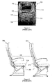
- FIG. 1 shows an image of a conventional airline seatback 100.
- Amenities that are commonly provided at the seatback 100 for the passenger's use during a long-haul flight may include In-Flight Entertainment (IFE) display 102, an IFE controller 104 at an upper portion of the seatback 100, a tray table 106 at adjacent middle portion of the seatback 100, a literature pocket 108, which holds e.g. safety information at a directly visible location for passengers when they are seated, at adjacent lower portion of the seatback 100, and other items such as a cup holder 110, and a coat hanger 112.
- IFE In-Flight Entertainment
- Figure 2 shows a schematic side view of two adjacent rows of conventional passenger seats illustrating legroom 202 between and a seat 204 and an aft seat 206, as well as seat pitch 208 between the seats 204, 206.
- the seat pitch 208 is kept as low as possible to maximize the number of rows of seats that may be installed.
- the legroom 202 as defined by the distance between an edge 210 of the aft seat 206 to a literature pocket 212 at the seatback of the seat 204, is about 27.2 cm (10.7 inches).
- Such an amount of legroom may be rather limited, especially for tall passengers.
- the seatback tray table 106 is typically pivotally mounted such that it can be stowed against the seatback 100 and hinged down and away from the seatback 100 into a generally horizontal position for use by the passenger seated aft of the seat.
- the cup holder 110 is usually installed on the tray table 106, and the coat hanger 112 is traditionally integrated with the tray table latch with a small hook due to space constrain. With such arrangements, when the tray table 106 is stowed, the cup holder 110 becomes inaccessible. The small hook is limited in use due to its size and position. This may cause some inconvenience to passengers.
- DE 42 27 064 A1 discloses a folding table for the rear of a vehicle seat.
- the folding table is normally stored in a vertical position behind the seat back and erects into a horizontal setting for use.
- the folding table comprises a main table leaf and an additional leaf mounted underneath the main table leaf, which can be pulled out into the operating position to either side of the main leaf.
- the additional leaf can be replaced by two or more sub-leaves to provide additional table area as required.
- DE 91 07 375 U1 discloses a table, in particular on the back of a seat, with at least one support as carrier of the table surface.
- the connection between the support and the table is via a tilting joint.
- the support and the table are foldable to the rear side of the seatback, wherein the table surface is arranged substantially parallel to the backrest back.
- WO2011/089558 A1 discloses a tray table arrangement for use by a passenger sitting in an aircraft seat.
- the tray table arrangement is supported by a support structure to allow it to be presented for use by the passenger, and comprises a bi-fold table comprising at least two juxtaposed table top members, a support arm extending between (i) the support structure and (ii) the bi-fold table, to support the bi-fold table.
- a seatback for a passenger seat comprising:
- the seatback may further comprise a pocket attached to the rear, wherein the the tray table, when in the stowage position, is at least partly transversely adjacent with pocket.
- the second half may be coupled to the first half by hinge means.
- the tray table may be slidable at the same transverse level to or from the base when in the use position.
- the seatback may further comprise at least one extendable rail connected to a respective one of the first half and second half for sliding the tray table to or from the base.
- the pocket may comprise an outwardly facing surface configured to receive at least one of a cup holder and a coat hanger.
- the cup holder and the coat hanger may be independently operable between a folded position in which the cup holder and the coat hanger may be flush with said surface, and a deployed position in which the cup holder and the coat hanger may extend away from said surface.
- the pocket may comprise an outwardly facing surface configured to support an electronic device mounted thereto.
- the pocket may be made of a rigid material.
- a passenger seat comprising a seatback as defined in claim 1.
- a method of manufacturing a seatback for a passenger seat comprising the steps of:
- the method may further comprise attaching at least one of a cup holder and a coat hanger to an outwardly facing surface of the pocket.
- Attaching at least one of a cup holder and a coat hanger to an outwardly facing surface of the pocket may comprise pivotally mounting each of said cup holder and said coat hanger to a complementary depression formed on said outwardly facing surface.
- the method may further comprise mounting a support for an electronic device to an outwardly facing surface of the pocket.
- embodiments of the present invention provide a seatback in which the tray table only occupies a portion of the width of the seatback. This is achieved e.g. with a table foldable along a latitudinal axis to fit into its new stowed position. With such tray table, the remaining width of the seatback may be used for the literature pocket so that the lower portion of the seatback is fully available as the passenger's legroom, as will be described in detail below.
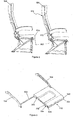
- Figure 3 shows a schematic perspective view of a seatback 300 according to an example embodiment.
- Figure 4 shows an alternate schematic perspective view of the seatback 300 of Figure 3 .
- the seatback 300 includes an upwardly extending base 302 which has a front 301 and a rear 303.
- the front 301 is capable of supporting a seated passenger.
- the rear 303 is made up of an upper portion 304, a middle portion 306 and a lower portion 308.
- the rear 303 has a longitudinal length 305 and a transverse width 307.
- a display 310 for in-flight entertainment and information is typically mounted at the upper portion 304 of the rear 303.
- Attached to one side of the middle portion 306 (e.g. the left side) of the rear 303 is a pocket 312, which includes an opening 314 for receiving printed materials such as a safety instruction leaflet, an in-flight magazine, etc. or small items such as earphones, an eye mask, etc.
- the pocket 312 can support a coat hanger 316 and/or a cup holder 318, as will be described later.
- the base 302 of the seatback 300 is made of a rigid material so as to support a seated passenger.
- the front 301 may include a cushioning material to improve the comfort level of the passenger.
- the base 302 may be rotatable by a predetermined amount about a bottom end 320 in a manner understood by a person skilled in the art, to allow the seated passenger to recline backward when desired.
- a tray table 322 is attached to the rear 303 of the base 302 by rigid support arms 324, 326, which are rotatable relative to the base 302 to move the tray table 322 between a use position and a stowage position.
- the tray table 322 provides a substantially flat surface that can support a variety of items, e.g. a food and beverage tray, a laptop computer, a book, etc. (not shown).
- the tray table 322 includes a first half 328 and a second half 330 that forms a contiguous surface with the first half 328 in the use position.
- the second half 330 is movably coupled to the first half 328 such that the second half 330 can be folded from the position shown in Figure 3 by 180° clockwise toward the first half 328, e.g. before stowage.
- the second half 330 is connected by to the first half 328 by hinges 332, 334 disposed along a center line 336 of the tray table 322.
- the second half of the table 330 may by 180° anticlockwise, toward the first half 328 before stowage using similar hinges.
- the literature pocket 312 may be attached to the right side of the middle portion 306 of the rear 303.
- the second half 330 is folded to the first half 328, and disposed between the base 302 and the first half 328.
- the tray table 322 as a whole is secured to the base 302 adjacent the middle portion 306 by a retaining lever 338.
- the tray table 322 is at least partly transversely aligned with pocket 312.
- the sizes of the tray table 322 and the pocket 312 are selected such that the tray table 312 occupies the remaining portion of the width of the rear 303 (e.g. the right half) not used by the pocket 312 when the tray table is in the stowage position.
- the positions of the tray table 322 and the pocket 312 in the transverse direction may be swapped as required, or desired.
- the legroom can be enhanced by fabricating the lower portion 308 with thicker edges 340, 342, 344 and a recessed central area 346, as shown in Figures 3-4 .
- Figure 5 shows a schematic side view of two adjacent rows of passenger seats illustrating legroom 502 between a seat 504 and an aft seat 506 both incorporating the seatback 300 of Figure 3 .
- the legroom 502 as defined by the distance between an edge 508 of the aft seat 506 to a lower portion 510 of a seatback 512 of the seat 504, is about 40 cm (12.2 inches), or an improvement of about 14% over the conventional passenger seats. This is based on the assumption that literature pocket has a thickness of 3.81 cm (1.5 inches).
- Figure 6 shows a schematic perspective view of the tray table 322 in a folded state.
- Figure 7 shows a schematic perspective view of the tray table 322 in an open state for use.
- a support bar 602 connects the arms 324, 326 and supports the tray table 322 in the position shown in Figure 6 .
- the hinges 332, 334 allows the second half 330 to be rotatable relative to the first half 328 between the folded state and open state. In the open state, side face 604 of the first half 328 abuts adjacent side face 606 of the second half 330, and limits the second half 330 from further rotation.
- the second half 330 includes a latch 802 that can releasably engage with a corresponding support member, e.g. key 804, fixedly mounted to one end of the arm 326.
- a corresponding support member e.g. key 804
- the latch 802 and the key 804 have mating protrusions 806, 808 and recesses 810, 812 that allow the key 804 to receive the latch 802 when the second half 330 is turned flat open.
- the key 804 thus can help to secure the second half 330 in the open state and transfer the weight of the second half 330 and any item placed thereon to the arm 326.
- Other mechanisms secure and support the second half 330 in the use position may be used in alternate embodiments.
- the tray table 322 is preferably slidable by a selected amount to or from the rear 303 of the base 302 ( Figure 3 ) while maintaining a substantially horizontal (i.e. transverse) level.
- Figure 9 shows the tray table 322 in the use position in which the tray table 322 extends away from the arms 324, 326 (i.e. toward a seated passenger - not shown).
- an extendable first rail 902 is pivotally mounted to the arm 324 at one end and received at the first half 328 at the other end to allow sliding movements by the first half 328.
- the latch 802 is formed at an end of an extendable second rail 904 which allows sliding movements by the second half 330 to or from the arm 326.
- the protrusion 808 on the key 804 interferes with the opposing protrusion 806 on the latch 802 and prevents dislodge when the tray table 322 is moved to or from the rear 303 of the base 302.
- the first rail 902 and second rail 904 can be, for example, rigid beams or tubes in telescopic engagement with elongated holes (not shown) formed on the first half 328 and second half 330 respectively
- an additional extendable third rail 906 may be integrated at the end of first half 328 towards second half 330, as indicated in Figure 9 (not shown in detail).
- the tray table 322 can provide similar functionality as conventional tray tables when in the use position, e.g. in terms of size, holding capacity, sliding movements, etc. while occupying a portion of the width of conventional tray tables when in the stowage position.
- such a configuration provides the space for attaching the pocket 312 ( Figure 3 ) to the middle portion 306 ( Figure 3 ) of the rear 303 of the base 302 ( Figure 3 ).
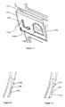
- FIG 11 shows a close-up view of the middle portion 306 of the rear 303 in Figure 3 illustrating the pocket 312.
- the pocket 312 is made of a rigid material such as plastic to support the weight of items placed therein via the opening 314, as well as the weight of a coat and/or a beverage cup suspending therefrom.
- An outwardly facing surface 1102 of the pocket 312 includes recesses 1104, 1106 shaped to receive the coat hanger 316 and the cup holder 318 respectively. The depths and profiles of the recesses 1104, 1106 are selected such that in the position shown in Figure 11 where the coat hanger 316 and the cup holder 318 are folded, the surface 1102 is substantially flush, i.e. no protrusion.
- Figures 12 and 13 which provide sectional views of the coat hanger 316 and the cup holder 318 respectively, the coat hanger 316 and the cup holder 318 are pivotally mounted to the pocket 312 by respective pins 1108, 1110.
- the pins 1108, 1110 allow the coat hanger 316 and cup holder 318 to be swung from the folded position to the deployed position.
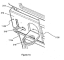
- Figure 14 shows a close up view similar to that in Figure 11 , with the coat hanger 312 and cup holder 318 now extend away from the surface 1102 and are ready for use.
- the arrangement as described above provides an independent coat hanger 316 that is also accessible and usable to the passenger all the time, and a cup holder 318 that is available all the time, especially during turbulence, irrespective of the tray table's positions.
- the coat hanger 318 is positioned nearer to and edge of the seatback 302 so that a coat suspended therefrom does not interfere with the use of the tray table.
- Figure 15 shows a schematic perspective view of a row of passenger seats 1502, 1504 each having the seatback of Figure 3 according to an example embodiment.
- the seatbacks 1506, 1508 provide substantially the same amenities as existing seatbacks, while increasing the legroom available to passengers seated behind seats 1502, 1504.
- the seatbacks 1506, 1508 can be used to replace existing seatbacks to enhance passengers' comfort without compromising on the number of rows of seats.
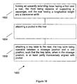
- FIG 16 shows a flow chart 1600 illustrating a method of manufacturing a seatback for a passenger seat according to an example embodiment.
- an upwardly extending base having a front and a rear is formed.
- the front is capable of supporting a passenger, and the rear has a longitudinal length and a transverse width.
- a pocket is attached to the rear.
- a tray table is attached to the rear, the tray table being operable between a stowage position and a use position, such that the tray table, when in the stowage position, is at least partly transversely aligned with pocket.
- the pocket may occupy more than half of the width of the seatback, and the tray table may be made up of 3 folding sections joined by hinges, instead of 2 halves.
- the outwardly facing surface of the pocket can be used for other purposes other than receiving the cup holder and/or coat hanger, such as creating a holder or support for an electronic device like a tablet, an e-book reader, an I-Pad, etc., provided that items created onto this surface will not be interrupted with the use of the tray table.
- the present embodiments are, therefore, to be considered in all respects to be illustrative and not restrictive.
Landscapes
- Engineering & Computer Science (AREA)
- Mechanical Engineering (AREA)
- Aviation & Aerospace Engineering (AREA)
- Transportation (AREA)
- Physics & Mathematics (AREA)
- Thermal Sciences (AREA)
- Chemical & Material Sciences (AREA)
- Combustion & Propulsion (AREA)
- Ocean & Marine Engineering (AREA)
- Vehicle Step Arrangements And Article Storage (AREA)
- Passenger Equipment (AREA)
- Seats For Vehicles (AREA)
- Chair Legs, Seat Parts, And Backrests (AREA)
Description
- The present invention relates broadly to passenger seats of an aircraft, train, vessel or vehicle, and more particularly, but not exclusively to a seatback of such a passenger seat.
- Legroom refers to available space to an aft seated passenger, which is commonly considered as a critical indicator of a passenger's comfort, especially for long-haul flights (e.g. more than 6 hours). Seat pitch refers to the distance between a point on one seat to the same point on the seat immediately in front. Seat pitch, depth of seatback structure, cushion and the amenities installed on the seatback may determine the legroom available to an aft seated passenger.
-
Figure 1 shows an image of aconventional airline seatback 100. Amenities that are commonly provided at theseatback 100 for the passenger's use during a long-haul flight may include In-Flight Entertainment (IFE)display 102, an IFEcontroller 104 at an upper portion of theseatback 100, a tray table 106 at adjacent middle portion of theseatback 100, aliterature pocket 108, which holds e.g. safety information at a directly visible location for passengers when they are seated, at adjacent lower portion of theseatback 100, and other items such as acup holder 110, and acoat hanger 112. These amenities often encroach on the space available to the aft seated passenger, thus reducing the passenger's legroom and potentially his comfort level. -
Figure 2 shows a schematic side view of two adjacent rows of conventional passengerseats illustrating legroom 202 between and aseat 204 and anaft seat 206, as well asseat pitch 208 between theseats seat pitch 208 is kept as low as possible to maximize the number of rows of seats that may be installed. In this example, for a seat pitch of 81.3 cm (32 inches), thelegroom 202, as defined by the distance between anedge 210 of theaft seat 206 to aliterature pocket 212 at the seatback of theseat 204, is about 27.2 cm (10.7 inches). Such an amount of legroom may be rather limited, especially for tall passengers. - With reference to
Figure 1 , the seatback tray table 106 is typically pivotally mounted such that it can be stowed against theseatback 100 and hinged down and away from theseatback 100 into a generally horizontal position for use by the passenger seated aft of the seat. Conventionally, thecup holder 110 is usually installed on the tray table 106, and thecoat hanger 112 is traditionally integrated with the tray table latch with a small hook due to space constrain. With such arrangements, when the tray table 106 is stowed, thecup holder 110 becomes inaccessible. The small hook is limited in use due to its size and position. This may cause some inconvenience to passengers. -
DE 42 27 064 A1 discloses a folding table for the rear of a vehicle seat. The folding table is normally stored in a vertical position behind the seat back and erects into a horizontal setting for use. The folding table comprises a main table leaf and an additional leaf mounted underneath the main table leaf, which can be pulled out into the operating position to either side of the main leaf. The additional leaf can be replaced by two or more sub-leaves to provide additional table area as required. -
DE 91 07 375 U1 discloses a table, in particular on the back of a seat, with at least one support as carrier of the table surface. The connection between the support and the table is via a tilting joint. The support and the table are foldable to the rear side of the seatback, wherein the table surface is arranged substantially parallel to the backrest back. -
WO2011/089558 A1 discloses a tray table arrangement for use by a passenger sitting in an aircraft seat. The tray table arrangement is supported by a support structure to allow it to be presented for use by the passenger, and comprises a bi-fold table comprising at least two juxtaposed table top members, a support arm extending between (i) the support structure and (ii) the bi-fold table, to support the bi-fold table. - More recently, there are passenger seats that provide an
independent cup holder 110 behind the tray table 106 (as shown inFigure 1 ), and in this case thecup holder 110 will not be accessible while the tray table 106 is deployed. Anindependent coat hanger 112 may be provided at the side of seat to move away from the tray table 106. However, this may cause confusion between passengers as to the correct hanger corresponding to their respective seats. - A need therefore exists to provide devices and methods that seek to address at least one of the above problems, or to provide a useful alternative.
- According to a first aspect of the present invention, and as defined in claim 1, there is provided a seatback for a passenger seat, the seatback comprising:
- an upwardly extending base having a front and a rear, the front capable of supporting a passenger; and
- a tray table pivotally attached to the rear of the base by first and second rotatable arms and operable between a stowage position and a use position, the tray table comprising a first half and a second half movably coupled to the first half such that the second half is substantially contiguous with the first half in the use position, and folded to the first half in the stowage position;
- wherein the rear has a longitudinal length and a transverse width, with the tray table, when in the stowage position, occupying a predetermined portion of the transverse width, and, when in the use position, extending rearwardly of the base and occupying substantially the whole transverse width;
- and wherein the first half is connected to the first rotatable arm, and the second half comprises a latch configured to engage with a support member connected to the second rotatable arm when the tray table is in the use position.
- The seatback may further comprise a pocket attached to the rear, wherein the the tray table, when in the stowage position, is at least partly transversely adjacent with pocket.
- The second half may be coupled to the first half by hinge means.
- The tray table may be slidable at the same transverse level to or from the base when in the use position.
- The seatback may further comprise at least one extendable rail connected to a respective one of the first half and second half for sliding the tray table to or from the base.
- The pocket may comprise an outwardly facing surface configured to receive at least one of a cup holder and a coat hanger.
- The cup holder and the coat hanger may be independently operable between a folded position in which the cup holder and the coat hanger may be flush with said surface, and a deployed position in which the cup holder and the coat hanger may extend away from said surface.
- The pocket may comprise an outwardly facing surface configured to support an electronic device mounted thereto.
- The pocket may be made of a rigid material.
- According to second aspect of the present invention, there is provided a passenger seat comprising a seatback as defined in claim 1.
- According to a third aspect of the present invention, and as defined in claim 9, there is provided a method of manufacturing a seatback for a passenger seat, the method comprising the steps of:
- forming an upwardly extending base having a front and a rear, the front being capable of supporting a passenger, and the rear having a longitudinal length and a transverse width;
- forming a tray table operable between a stowage position and a use position, wherein the tray table comprises a first half and a second half movably coupled to the first half such that the second half is substantially contiguous with the first half in the use position, and folded to the first half in the stowage position and such that the tray table, when in the stowage position, occupies a predetermined portion of the transverse width, and, when in the use position, extends rearwardly of the base and occupies substantially the whole transverse width; and
- attaching the tray table to the rear of the base by first and second rotatable arms such that the first half of the tray table is connected to the first rotatable arm;
- wherein the second half comprises a latch configured to engage with a support member connected to the second rotatable arm when the tray table is in the use position.
- The method may further comprise attaching at least one of a cup holder and a coat hanger to an outwardly facing surface of the pocket.
- Attaching at least one of a cup holder and a coat hanger to an outwardly facing surface of the pocket may comprise pivotally mounting each of said cup holder and said coat hanger to a complementary depression formed on said outwardly facing surface.
- The method may further comprise mounting a support for an electronic device to an outwardly facing surface of the pocket.
- Embodiments of the invention will be better understood and readily apparent to one of ordinary skill in the art from the following written description, by way of example only, and in conjunction with the drawings, in which:
-
Figure 1 shows an image of a conventional airline seatback. -
Figure 2 shows a schematic side view of two adjacent rows of conventional passenger seats. -
Figure 3 shows a schematic perspective view of a seatback according to an example embodiment. -
Figure 4 shows an alternate schematic perspective view of the seatback ofFigure 3 . -
Figure 5 shows a schematic side view of two adjacent rows of passenger seats incorporating the seatback ofFigure 3 . -
Figure 6 shows a schematic perspective view of the tray table ofFigure 3 in a folded state. -
Figure 7 shows a schematic perspective view of the tray table ofFigure 3 in an open state for use. -
Figure 8 shows a close-up view from below the tray table ofFigure 7 . -
Figure 9 shows the tray table ofFigure 7 in an extended position. -
Figure 10 shows a close-up view of a corner of the tray table in the position ofFigure 9 . -
Figure 11 shows a close-up view of pocket ofFigure 3 with the coat hanger and cup holder folded. -
Figure 12 shows a sectional view of the coat hanger ofFigure 11 . -
Figure 13 shows a sectional view of the cup holder ofFigure 11 . -
Figure 14 shows the pocket ofFigure 11 with the coat hanger and cup holder extended. -
Figure 15 shows a schematic perspective view of a row of passenger seats having the seatbacks ofFigure 3 according to an example embodiment. -
Figure 16 shows a flow chart illustrating a method of manufacturing a seatback for a passenger seat according to an example embodiment. - In an effort to create more legroom, embodiments of the present invention provide a seatback in which the tray table only occupies a portion of the width of the seatback. This is achieved e.g. with a table foldable along a latitudinal axis to fit into its new stowed position. With such tray table, the remaining width of the seatback may be used for the literature pocket so that the lower portion of the seatback is fully available as the passenger's legroom, as will be described in detail below.
-
Figure 3 shows a schematic perspective view of aseatback 300 according to an example embodiment.Figure 4 shows an alternate schematic perspective view of theseatback 300 ofFigure 3 . - The
seatback 300 includes an upwardly extendingbase 302 which has a front 301 and a rear 303. The front 301 is capable of supporting a seated passenger. The rear 303 is made up of anupper portion 304, amiddle portion 306 and alower portion 308. In addition, the rear 303 has alongitudinal length 305 and atransverse width 307. - A
display 310 for in-flight entertainment and information is typically mounted at theupper portion 304 of the rear 303. Attached to one side of the middle portion 306 (e.g. the left side) of the rear 303 is apocket 312, which includes anopening 314 for receiving printed materials such as a safety instruction leaflet, an in-flight magazine, etc. or small items such as earphones, an eye mask, etc. Thepocket 312 can support acoat hanger 316 and/or acup holder 318, as will be described later. Typically, thebase 302 of theseatback 300 is made of a rigid material so as to support a seated passenger. The front 301 may include a cushioning material to improve the comfort level of the passenger. Also, thebase 302 may be rotatable by a predetermined amount about abottom end 320 in a manner understood by a person skilled in the art, to allow the seated passenger to recline backward when desired. - A tray table 322 is attached to the rear 303 of the base 302 by
rigid support arms Figure 3 , the tray table 322 provides a substantially flat surface that can support a variety of items, e.g. a food and beverage tray, a laptop computer, a book, etc. (not shown). As also shown inFigure 3 , the tray table 322 includes afirst half 328 and asecond half 330 that forms a contiguous surface with thefirst half 328 in the use position. Here, thesecond half 330 is movably coupled to thefirst half 328 such that thesecond half 330 can be folded from the position shown inFigure 3 by 180° clockwise toward thefirst half 328, e.g. before stowage. For example, thesecond half 330 is connected by to thefirst half 328 byhinges center line 336 of the tray table 322. Alternatively, the second half of the table 330 may by 180° anticlockwise, toward thefirst half 328 before stowage using similar hinges. Theliterature pocket 312 may be attached to the right side of themiddle portion 306 of the rear 303. - In the stowage position, as shown in
Figure 4 , thesecond half 330 is folded to thefirst half 328, and disposed between the base 302 and thefirst half 328. The tray table 322 as a whole is secured to the base 302 adjacent themiddle portion 306 by a retaininglever 338. In other words, the tray table 322 is at least partly transversely aligned withpocket 312. For example, the sizes of the tray table 322 and thepocket 312 are selected such that the tray table 312 occupies the remaining portion of the width of the rear 303 (e.g. the right half) not used by thepocket 312 when the tray table is in the stowage position. The positions of the tray table 322 and thepocket 312 in the transverse direction may be swapped as required, or desired. - As described, by re-arranging the position of the
pocket 312 on the rear 303 of thebase 302, the space adjacent thelower portion 308 of the rear 303 is freed up for the seated passenger's legroom. Moreover, the legroom can be enhanced by fabricating thelower portion 308 withthicker edges central area 346, as shown inFigures 3-4 . -
Figure 5 shows a schematic side view of two adjacent rows of passengerseats illustrating legroom 502 between aseat 504 and anaft seat 506 both incorporating theseatback 300 ofFigure 3 . For illustration purpose, using the same seat pitch of 81.3 cm (32 inches), thelegroom 502, as defined by the distance between anedge 508 of theaft seat 506 to alower portion 510 of aseatback 512 of theseat 504, is about 40 cm (12.2 inches), or an improvement of about 14% over the conventional passenger seats. This is based on the assumption that literature pocket has a thickness of 3.81 cm (1.5 inches). - An example implementation of the tray table 322 of
Figure 3 is now described with reference toFigures 6-10 . Here, the like parts are denoted with like references, including those used inFigure 3 . -
Figure 6 shows a schematic perspective view of the tray table 322 in a folded state.Figure 7 shows a schematic perspective view of the tray table 322 in an open state for use. Asupport bar 602 connects thearms Figure 6 . The hinges 332, 334 allows thesecond half 330 to be rotatable relative to thefirst half 328 between the folded state and open state. In the open state, side face 604 of thefirst half 328 abutsadjacent side face 606 of thesecond half 330, and limits thesecond half 330 from further rotation. - In addition, as shown more clearly in
Figure 8 which provides a view from below the tray table 322, thesecond half 330 includes alatch 802 that can releasably engage with a corresponding support member, e.g. key 804, fixedly mounted to one end of thearm 326. For example thelatch 802 and the key 804 havemating protrusions latch 802 when thesecond half 330 is turned flat open. The key 804 thus can help to secure thesecond half 330 in the open state and transfer the weight of thesecond half 330 and any item placed thereon to thearm 326. Other mechanisms secure and support thesecond half 330 in the use position may be used in alternate embodiments. - In the use position, the tray table 322 is preferably slidable by a selected amount to or from the rear 303 of the base 302 (
Figure 3 ) while maintaining a substantially horizontal (i.e. transverse) level.Figure 9 shows the tray table 322 in the use position in which the tray table 322 extends away from thearms 324, 326 (i.e. toward a seated passenger - not shown). For example, an extendablefirst rail 902 is pivotally mounted to thearm 324 at one end and received at thefirst half 328 at the other end to allow sliding movements by thefirst half 328. Also, as shown more clearly inFigure 10 which provides a close-up view of a corner of thesecond half 330, thelatch 802 is formed at an end of an extendablesecond rail 904 which allows sliding movements by thesecond half 330 to or from thearm 326. Here, theprotrusion 808 on the key 804 interferes with the opposingprotrusion 806 on thelatch 802 and prevents dislodge when the tray table 322 is moved to or from the rear 303 of thebase 302. Thefirst rail 902 andsecond rail 904 can be, for example, rigid beams or tubes in telescopic engagement with elongated holes (not shown) formed on thefirst half 328 andsecond half 330 respectively In some embodiments, an additional extendablethird rail 906 may be integrated at the end offirst half 328 towardssecond half 330, as indicated inFigure 9 (not shown in detail). - As described, the tray table 322 can provide similar functionality as conventional tray tables when in the use position, e.g. in terms of size, holding capacity, sliding movements, etc. while occupying a portion of the width of conventional tray tables when in the stowage position. In the example embodiment, such a configuration provides the space for attaching the pocket 312 (
Figure 3 ) to the middle portion 306 (Figure 3 ) of the rear 303 of the base 302 (Figure 3 ). - An example implementation of the
pocket 312 is now described with reference toFigures 11-14 . Here, the like parts are denoted with like references, including those used inFigure 3 . -
Figure 11 shows a close-up view of themiddle portion 306 of the rear 303 inFigure 3 illustrating thepocket 312. Typically, thepocket 312 is made of a rigid material such as plastic to support the weight of items placed therein via theopening 314, as well as the weight of a coat and/or a beverage cup suspending therefrom. An outwardly facingsurface 1102 of thepocket 312 includesrecesses coat hanger 316 and thecup holder 318 respectively. The depths and profiles of therecesses Figure 11 where thecoat hanger 316 and thecup holder 318 are folded, thesurface 1102 is substantially flush, i.e. no protrusion. - Moreover, as shown in
Figures 12 and 13 which provide sectional views of thecoat hanger 316 and thecup holder 318 respectively, thecoat hanger 316 and thecup holder 318 are pivotally mounted to thepocket 312 byrespective pins pins coat hanger 316 andcup holder 318 to be swung from the folded position to the deployed position.Figure 14 shows a close up view similar to that inFigure 11 , with thecoat hanger 312 andcup holder 318 now extend away from thesurface 1102 and are ready for use. - The arrangement as described above provides an
independent coat hanger 316 that is also accessible and usable to the passenger all the time, and acup holder 318 that is available all the time, especially during turbulence, irrespective of the tray table's positions. Preferably, thecoat hanger 318 is positioned nearer to and edge of theseatback 302 so that a coat suspended therefrom does not interfere with the use of the tray table. -
Figure 15 shows a schematic perspective view of a row ofpassenger seats Figure 3 according to an example embodiment. Theseatbacks seats seatbacks -
Figure 16 shows aflow chart 1600 illustrating a method of manufacturing a seatback for a passenger seat according to an example embodiment. Atstep 1602, an upwardly extending base having a front and a rear is formed. The front is capable of supporting a passenger, and the rear has a longitudinal length and a transverse width. Atstep 1604, a pocket is attached to the rear. Atstep 1606, a tray table is attached to the rear, the tray table being operable between a stowage position and a use position, such that the tray table, when in the stowage position, is at least partly transversely aligned with pocket. - It will be appreciated by a person skilled in the art that numerous variations and/or modifications may be made to the present invention as shown in the specific embodiments without departing from the scope of the invention as broadly described. For example, the pocket may occupy more than half of the width of the seatback, and the tray table may be made up of 3 folding sections joined by hinges, instead of 2 halves. The outwardly facing surface of the pocket can be used for other purposes other than receiving the cup holder and/or coat hanger, such as creating a holder or support for an electronic device like a tablet, an e-book reader, an I-Pad, etc., provided that items created onto this surface will not be interrupted with the use of the tray table. The present embodiments are, therefore, to be considered in all respects to be illustrative and not restrictive.
Claims (12)
- A seatback (300) for a passenger seat, the seatback (300) comprising:an upwardly extending base (302) having a front (301) and a rear (303), the front (301) capable of supporting a passenger; anda tray table (322) pivotally attached to the rear (303) of the base (302) by first and second rotatable arms (324, 326) and operable between a stowage position and a use position, the tray table (322) comprising a first half (328) and a second half (330) movably coupled to the first half (328) such that the second half (330) is substantially contiguous with the first half (328) in the use position, and folded to the first half (328) in the stowage position;wherein the rear (303) has a longitudinal length (305) and a transverse width (307), with the tray table (322), when in the stowage position, occupying a predetermined portion of the transverse width (307), and, when in the use position, extending rearward of the base (302) and occupying substantially the whole transverse width (307);and wherein the first half (328) is connected to the first rotatable arm (324), and the second half (330) comprises a latch (802) configured to engage with a support member (804) connected to the second rotatable arm (326) when the tray table (322) is in the use position.
- The seatback (300) as claimed in claim 1, further comprising a pocket (312) attached to the rear (303), wherein the tray table (322), when in the stowage position, is transversely adjacent the pocket (312).
- The seatback (300) as claimed in claim 1, wherein the second half (330) of the tray table (322) is coupled to the first half (328) of the tray table (322) by hinge means (332, 334).
- The seatback (300) as claimed in any one of claims 1 to 3, wherein the tray table (322) is slidable at the same transverse level to or from the base (302) when in the use position.
- The seatback (300) as claimed in claim 4, further comprising at least one extendable rail (902, 904) connected to a respective one of the first half (328) and second half (330) for sliding the tray table (322) to or from the base (302).
- The seatback (300) as claimed in any one of claims 2 to 5, wherein the pocket (312) comprises an outwardly facing surface (1102) configured to receive at least one of a cup holder (318) and a coat hanger (316), and wherein the cup holder (318) and the coat hanger (316) are independently operable between a folded position in which the cup holder (318) and the coat hanger (316) are flush with said surface (1102), and a deployed position in which the cup holder (318) and the coat hanger (316) extend away from said surface (1102).
- The seatback (300) as claimed in any one of claims 2 to 5, wherein the pocket (312) comprises an outwardly facing surface (1102) configured to support an electronic device mounted thereto.
- A passenger seat (1502, 1504) comprising a seatback (300) as claimed in any one of the preceding claims.
- A method of manufacturing a seatback (300) for a passenger seat (1502, 1504), comprising:forming an upwardly extending base (302) having a front (301) and a rear (303), the front (301) being capable of supporting a passenger, and the rear (303) having a longitudinal length (305) and a transverse width (307);forming a tray table (322) operable between a stowage position and a use position, wherein the tray table (322) comprises a first half (328) and a second half (328) movably coupled to the first half (328) such that the second half (330) is substantially contiguous with the first half (328) in the use position, and folded to the first half (328) in the stowage position and such that the tray table (322), when in the stowage position, occupies a predetermined portion of the transverse width (307), and, when in the use position, extends rearward of the base (302) and occupies substantially the whole transverse width (307); andattaching the tray table (322) to the rear (303) of the base (302) by first and second rotatable arms (324, 326) such that the first half (328) of the tray table (322) is connected to the first rotatable arm (324);wherein the second half (330) comprises a latch (802) configured to engage with a support member (804) connected to the second rotatable arm (326) when the tray table (322) is in the use position.
- The method as claimed in claim 9, further comprising attaching a pocket (312) to the rear (303) such that the tray table (322), when in the stowage position, is transversely adjacent the pocket (312).
- The method as claimed in claim 10, further comprising attaching at least one of a cup holder (318) and a coat hanger (316) to an outwardly facing surface (1102) of the pocket (312) by pivotally mounting each of said cup holder (318) and said coat hanger (316) to a complementary depression (1104, 1106) formed on said outwardly facing surface (1102).
- The method as claimed in claim 10, further comprising attaching a support for an electronic device to an outwardly facing surface (1102) of the pocket (312).
Applications Claiming Priority (2)
| Application Number | Priority Date | Filing Date | Title |
|---|---|---|---|
| SG2013052030A SG2013052030A (en) | 2013-07-04 | 2013-07-04 | A seatback for a passenger seat |
| PCT/SG2014/000295 WO2015002609A1 (en) | 2013-07-04 | 2014-06-20 | A seatback for a passenger seat |
Publications (3)
| Publication Number | Publication Date |
|---|---|
| EP3016550A1 EP3016550A1 (en) | 2016-05-11 |
| EP3016550A4 EP3016550A4 (en) | 2017-03-22 |
| EP3016550B1 true EP3016550B1 (en) | 2019-10-16 |
Family
ID=55167880
Family Applications (1)
| Application Number | Title | Priority Date | Filing Date |
|---|---|---|---|
| EP14819995.3A Active EP3016550B1 (en) | 2013-07-04 | 2014-06-20 | A seatback for a passenger seat |
Country Status (6)
| Country | Link |
|---|---|
| US (1) | US9610879B2 (en) |
| EP (1) | EP3016550B1 (en) |
| JP (1) | JP6529490B2 (en) |
| CN (1) | CN105992533B (en) |
| SG (1) | SG2013052030A (en) |
| WO (1) | WO2015002609A1 (en) |
Families Citing this family (42)
| Publication number | Priority date | Publication date | Assignee | Title |
|---|---|---|---|---|
| US9016627B2 (en) | 2009-10-02 | 2015-04-28 | Panasonic Avionics Corporation | System and method for providing an integrated user interface system at a seat |
| EP2917105B1 (en) * | 2012-11-12 | 2019-06-19 | Safran Seats USA LLC | Integrated keyboard tray |
| US9630717B2 (en) | 2013-04-26 | 2017-04-25 | Encore Interiors, Inc. | Aircraft seating assembly with reduced spacing |
| EP3128873B1 (en) * | 2014-04-07 | 2018-09-26 | B/E Aerospace, Inc. | Laterally-expanding tray table |
| US9919802B2 (en) * | 2014-04-07 | 2018-03-20 | B/E Aerospace, Inc. | Laterally-expanding tray table |
| EP3227183B1 (en) * | 2014-12-01 | 2020-06-10 | Safran Seats USA LLC | Tray table assembly |
| JP6387836B2 (en) * | 2015-01-08 | 2018-09-12 | トヨタ紡織株式会社 | Vehicle seat |
| EP3042852A1 (en) * | 2015-01-09 | 2016-07-13 | Geven S.p.A. | Improved folding table, having an integrated pocket for housing magazines, for a seat, preferably airplane seat |
| US9764844B2 (en) | 2015-04-13 | 2017-09-19 | Encore Seats, Inc. | Aircraft seating assembly |
| FR3041574B1 (en) * | 2015-09-29 | 2018-09-07 | C-Gex System's | PASSENGER SEAT HYGIENE ACCESSORY AND METHOD FOR SERVICING PASSENGER TRANSPORT DEVICE |
| GB2548409B (en) * | 2016-03-18 | 2020-02-19 | Acro Aircraft Seating Ltd | Table leg |
| US9821887B1 (en) * | 2016-03-31 | 2017-11-21 | Brunswick Corporation | Convertible leaning post seating system for marine vessels |
| US10144515B2 (en) | 2016-04-01 | 2018-12-04 | Encore Seats, Inc. | Aircraft seating assembly and components |
| WO2017176722A1 (en) * | 2016-04-04 | 2017-10-12 | B/E Aerospace, Inc. | Tray table deployable from lower seatback area |
| WO2017192875A1 (en) * | 2016-05-05 | 2017-11-09 | Timco Aviation Services, Inc. | Seat system |
| US9751630B1 (en) * | 2016-06-28 | 2017-09-05 | Recaro Aircraft Seating Gmbh & Co. Kg | Tray table device |
| US20180339777A1 (en) * | 2017-05-26 | 2018-11-29 | AirGo Design Pte., Ltd. | High backrest passenger seat |
| US10538334B2 (en) * | 2017-10-25 | 2020-01-21 | Rockwell Collins, Inc. | Underseat replaceable in-flight entertainment cabling assembly |
| CN109318775B (en) * | 2018-09-29 | 2021-01-15 | 慈溪市龙山汽配有限公司 | Multifunctional automobile seat |
| CN111071124B (en) * | 2018-10-18 | 2024-05-10 | 迈利德机械(太仓)有限公司 | Folding table for automobile |
| US11180254B2 (en) | 2019-05-24 | 2021-11-23 | AirGo Design Pte., Ltd. | Space-efficient flat-bed seating arrangement |
| US10946967B2 (en) * | 2019-06-10 | 2021-03-16 | B/E Aerospace, Inc. | Aircraft seat deployable bridge table, mounting provisions, and storage provisions |
| US11312495B2 (en) * | 2019-08-30 | 2022-04-26 | The Boeing Company | Compact seat assembly for a vehicle |
| EP3816050B1 (en) * | 2019-10-29 | 2025-01-01 | B/E Aerospace, Inc. | Display bezel with plugin accessories |
| US11034453B1 (en) * | 2019-10-29 | 2021-06-15 | B/E Aerospace, Inc. | Bezel-mounted seat privacy closeout |
| US11034454B1 (en) * | 2019-11-06 | 2021-06-15 | B/E Aerospace, Inc. | Seat spreader mounted seat privacy closeout |
| CN111301688A (en) * | 2019-12-30 | 2020-06-19 | 高博通信(上海)有限公司 | Aviation seat |
| EP4232362B1 (en) * | 2020-10-21 | 2026-05-20 | Safran Seats Usa Llc | Tray table with comfort features for one passenger seat |
| US12060138B1 (en) | 2020-12-01 | 2024-08-13 | Brunswick Corporation | Convertible seating and bed system for marine vessels |
| US12128992B1 (en) | 2020-12-01 | 2024-10-29 | Brunswick Corporation | Convertible seating system for marine vessels |
| CN112793516B (en) * | 2021-01-06 | 2023-06-27 | 广东轻工职业技术学院 | Vehicle-mounted multimedia mobile platform capable of facilitating passengers to get in and out |
| US11583094B2 (en) | 2021-05-20 | 2023-02-21 | Daniel LaSalle | Method and apparatus for holding a book or other handheld object |
| US12258100B1 (en) | 2022-01-28 | 2025-03-25 | Brunswick Corporation | Convertible seating systems for marine vessels |
| US12357097B1 (en) | 2022-06-08 | 2025-07-15 | Brunswick Corporation | Convertible seating for marine vessels |
| IT202200012449A1 (en) * | 2022-06-13 | 2023-12-13 | Geven S P A | Folding table, and seat with backrest that incorporates it |
| US12043157B2 (en) * | 2022-06-27 | 2024-07-23 | B/E Aerospace, Inc. | Deployable elastomeric bottle holster |
| US12522356B2 (en) * | 2022-07-13 | 2026-01-13 | Supernal, Llc | Methods, systems, and devices for a seat for a vehicle |
| US12441473B2 (en) * | 2022-09-07 | 2025-10-14 | B/E Aerospace, Inc. | System including stowable cupholder apparatus |
| US12479579B2 (en) * | 2023-03-30 | 2025-11-25 | B/E Aerospace, Inc. | Passenger seat with self-stowing portable electronic device holder |
| FR3147791B1 (en) * | 2023-04-14 | 2025-02-28 | Safran Seats | LOCKING DEVICE FOR A TABLET AND AN ADDITIONAL SUPPORT |
| DE102023114747A1 (en) * | 2023-06-05 | 2024-12-05 | Recaro Aircraft Seating Gmbh & Co. Kg | seat device with an interface module |
| US20260028123A1 (en) * | 2024-07-24 | 2026-01-29 | B/E Aerospace, Inc. | Aircraft seatback tray table module |
Family Cites Families (40)
| Publication number | Priority date | Publication date | Assignee | Title |
|---|---|---|---|---|
| US3632161A (en) * | 1970-07-13 | 1972-01-04 | Universal Oil Prod Co | Side arm stowable table |
| US3773381A (en) | 1972-05-08 | 1973-11-20 | Universal Oil Prod Co | Compact tray table |
| US4159071A (en) * | 1978-01-27 | 1979-06-26 | Hank Roca | Pivotable utility table |
| US4944552A (en) * | 1989-03-17 | 1990-07-31 | Weber Aircraft, Inc. | Stowable table system |
| DE9107375U1 (en) * | 1991-06-14 | 1991-08-01 | Karl Kässbohrer Fahrzeugwerke GmbH, 7900 Ulm | Table |
| DE4227064A1 (en) * | 1992-08-15 | 1993-10-14 | Daimler Benz Ag | Folding table |
| DE4340189A1 (en) * | 1993-11-25 | 1995-06-01 | Immanuel Haffner Fa | Seat for a means of transport |
| DE4343242C2 (en) | 1993-12-17 | 1997-05-15 | Bayerische Motoren Werke Ag | Stowable table furniture on one seat |
| US5547247A (en) * | 1994-08-16 | 1996-08-20 | Burns Aerospace Corporation | Passenger tray table with ingress/egress position |
| JPH09220962A (en) * | 1996-02-16 | 1997-08-26 | Central Motor Co Ltd | Cup holder support structure |
| US5878672A (en) | 1997-06-23 | 1999-03-09 | Ostermann; Heather M. | Portable organizer desk for use while traveling |
| US5876092A (en) * | 1997-12-05 | 1999-03-02 | Industrial Technology Research Institute | Foldaway table behind the backrest of a seat |
| ES2228671T3 (en) * | 2000-03-09 | 2005-04-16 | Airbus Deutschland Gmbh | PASSENGER SEAT WITH A DEVICE TO ACCOMMODATE SEAT ACCESSORIES AND WASTE. |
| DE10027230B4 (en) * | 2000-05-31 | 2004-01-15 | Recaro Aircraft Seating Gmbh & Co. | table unit |
| US6761398B2 (en) * | 2001-05-25 | 2004-07-13 | Weber Aircraft Lp | Stowable tables |
| US6454349B1 (en) * | 2001-07-27 | 2002-09-24 | The Boeing Company | Pivoting tray table assembly |
| US20030184957A1 (en) * | 2002-04-02 | 2003-10-02 | Stahl Robert Edward | Computer keyboard integrated in aircraft seatback tray table |
| DE20207355U1 (en) * | 2002-05-08 | 2002-08-29 | Berger, Georg, 44797 Bochum | Folding table for a seat in a means of transport |
| US7004430B2 (en) * | 2002-06-12 | 2006-02-28 | Weekly Roy L | Threat-resistant aircraft tray |
| DE102004004339B4 (en) * | 2004-01-29 | 2020-06-04 | Recaro Aircraft Seating Gmbh & Co. Kg | Passenger seat |
| CN2740460Y (en) * | 2004-09-17 | 2005-11-16 | E·I·S·飞机有限责任公司 | Seat folding tables for use in vehicles |
| JP4260124B2 (en) * | 2005-03-01 | 2009-04-30 | 小糸工業株式会社 | Aircraft seat |
| CN1785711A (en) * | 2005-12-13 | 2006-06-14 | 王文军 | Folding table set on seat back of communication facility |
| JP2007253914A (en) * | 2006-03-27 | 2007-10-04 | Mitsubishi Fuso Truck & Bus Corp | Seat back table |
| JP2008168884A (en) * | 2007-01-10 | 2008-07-24 | Yoshika Kimura | Storage table plate incorporated into backrest of front passenger seat |
| US8141948B2 (en) * | 2007-05-11 | 2012-03-27 | Audiovox Corporation | Seat back entertainment system |
| US8312819B2 (en) * | 2007-12-10 | 2012-11-20 | Weber Aircraft Llc | Expansion and retraction mechanisms for moveable tray tables |
| US7506923B1 (en) * | 2008-04-10 | 2009-03-24 | Be Aerospace, Inc. | Adjustable bi-fold tray table |
| EP2391541B1 (en) * | 2009-01-30 | 2019-07-24 | Air New Zealand Limited | Seating arrangement, seat unit, tray table and seating system |
| ZA201004330B (en) * | 2009-09-21 | 2011-02-23 | Inviseo Media Holdings Ltd | Vorrichtung zur augnahme eines infornationsmediums |
| WO2011089558A1 (en) * | 2010-01-20 | 2011-07-28 | Air New Zealand Limited | A tray table arrangement |
| CA2787420A1 (en) * | 2010-01-29 | 2011-08-04 | Weber Aircraft Llc | Seat back assembly |
| CN201932044U (en) * | 2010-11-25 | 2011-08-17 | 浙江吉利汽车研究院有限公司 | Multifunctional automobile chair |
| US20120139303A1 (en) * | 2010-12-07 | 2012-06-07 | Rik Westerink | Display assembly |
| GB201107061D0 (en) * | 2011-04-27 | 2011-06-08 | Bentley Motors Ltd | Vehicle seat and trim |
| US8997660B2 (en) * | 2012-03-23 | 2015-04-07 | Johnny A. Satterfield | Deployable table assembly |
| DE202012105089U1 (en) * | 2012-12-28 | 2013-01-29 | Airbus Operations Gmbh | Storage arrangement for a vehicle, passenger seat and aircraft |
| US9398805B2 (en) * | 2013-02-28 | 2016-07-26 | Zodiac Seats Us Llc | Track roller food table slide |
| US9216695B2 (en) * | 2013-08-05 | 2015-12-22 | Ford Global Technologies, Llc | Small storage pockets for a vehicle seat assembly |
| US9180805B2 (en) * | 2013-08-29 | 2015-11-10 | Reinhold Industries, Inc. | Adjustable utility tray |
-
2013
- 2013-07-04 SG SG2013052030A patent/SG2013052030A/en unknown
-
2014
- 2014-06-20 JP JP2016523706A patent/JP6529490B2/en active Active
- 2014-06-20 EP EP14819995.3A patent/EP3016550B1/en active Active
- 2014-06-20 CN CN201480037744.9A patent/CN105992533B/en active Active
- 2014-06-20 WO PCT/SG2014/000295 patent/WO2015002609A1/en not_active Ceased
- 2014-06-20 US US14/902,236 patent/US9610879B2/en active Active
Non-Patent Citations (1)
| Title |
|---|
| None * |
Also Published As
| Publication number | Publication date |
|---|---|
| JP2016525477A (en) | 2016-08-25 |
| CN105992533A (en) | 2016-10-05 |
| JP6529490B2 (en) | 2019-06-12 |
| WO2015002609A1 (en) | 2015-01-08 |
| EP3016550A4 (en) | 2017-03-22 |
| CN105992533B (en) | 2019-02-05 |
| SG2013052030A (en) | 2015-02-27 |
| US9610879B2 (en) | 2017-04-04 |
| EP3016550A1 (en) | 2016-05-11 |
| US20160152169A1 (en) | 2016-06-02 |
Similar Documents
| Publication | Publication Date | Title |
|---|---|---|
| US9610879B2 (en) | Seatback for a passenger seat | |
| EP2799338B1 (en) | Configurable tray table | |
| EP2209402B1 (en) | Convertible passenger seat assembly | |
| EP3129289B1 (en) | A seat unit | |
| EP3653505B1 (en) | Recliner sofa system for economy class seat | |
| EP2726373B1 (en) | Multipurpose tray | |
| US10875652B2 (en) | Passenger tray table | |
| US7966952B2 (en) | Foldable table for aircraft interiors | |
| CN103347784B (en) | slide out bed cabin | |
| EP2981464B1 (en) | A support structure for attachment to a tray table for a passenger seat, tray table for a passenger seat, and passenger seat | |
| EP3128873B1 (en) | Laterally-expanding tray table | |
| EP3594122A1 (en) | Aircraft seating configuration | |
| US20180116391A1 (en) | Table For Aircraft Interiors | |
| WO2007123615A1 (en) | Tray tables principally for use in passenger vehicles | |
| CN101595032A (en) | Seat device in vehicle cockpit | |
| EP3722209B1 (en) | Passenger entertainment device, passenger seat arrangement and vehicle | |
| WO2018187070A1 (en) | Seat system with stowable tray | |
| WO2017087602A1 (en) | Integral tray table personal electronic device holder and tray table | |
| WO2020263262A1 (en) | Deployable support surface formed from upper shroud | |
| WO2017147620A1 (en) | Tray table with adjustable media support surface | |
| EP3819216B1 (en) | Seat spreader mounted seat privacy closeout | |
| US12172581B2 (en) | Deployable personal entertainment device holder |
Legal Events
| Date | Code | Title | Description |
|---|---|---|---|
| PUAI | Public reference made under article 153(3) epc to a published international application that has entered the european phase |
Free format text: ORIGINAL CODE: 0009012 |
|
| 17P | Request for examination filed |
Effective date: 20151231 |
|
| AK | Designated contracting states |
Kind code of ref document: A1 Designated state(s): AL AT BE BG CH CY CZ DE DK EE ES FI FR GB GR HR HU IE IS IT LI LT LU LV MC MK MT NL NO PL PT RO RS SE SI SK SM TR |
|
| AX | Request for extension of the european patent |
Extension state: BA ME |
|
| RIN1 | Information on inventor provided before grant (corrected) |
Inventor name: ZHENG, GUO YING Inventor name: YOSHIMURA, TOMOYUKI Inventor name: TAN, WEE HONG ANNA |
|
| DAX | Request for extension of the european patent (deleted) | ||
| A4 | Supplementary search report drawn up and despatched |
Effective date: 20170216 |
|
| RIC1 | Information provided on ipc code assigned before grant |
Ipc: B60N 3/10 20060101AFI20170210BHEP Ipc: B60N 3/00 20060101ALI20170210BHEP Ipc: B64D 11/06 20060101ALI20170210BHEP |
|
| RAP1 | Party data changed (applicant data changed or rights of an application transferred) |
Owner name: TENRYU HOLDINGS CO., LTD. Owner name: ST ENGINEERING AEROSPACE LTD. |
|
| REG | Reference to a national code |
Ref country code: DE Ref legal event code: R079 Ref document number: 602014055347 Country of ref document: DE Free format text: PREVIOUS MAIN CLASS: A47C0007700000 Ipc: B64D0011060000 |
|
| RIC1 | Information provided on ipc code assigned before grant |
Ipc: B60N 3/00 20060101ALI20190328BHEP Ipc: B64D 11/06 20060101AFI20190328BHEP Ipc: B64D 11/00 20060101ALI20190328BHEP Ipc: B60N 3/10 20060101ALI20190328BHEP |
|
| GRAP | Despatch of communication of intention to grant a patent |
Free format text: ORIGINAL CODE: EPIDOSNIGR1 |
|
| STAA | Information on the status of an ep patent application or granted ep patent |
Free format text: STATUS: GRANT OF PATENT IS INTENDED |
|
| INTG | Intention to grant announced |
Effective date: 20190506 |
|
| GRAS | Grant fee paid |
Free format text: ORIGINAL CODE: EPIDOSNIGR3 |
|
| GRAA | (expected) grant |
Free format text: ORIGINAL CODE: 0009210 |
|
| STAA | Information on the status of an ep patent application or granted ep patent |
Free format text: STATUS: THE PATENT HAS BEEN GRANTED |
|
| AK | Designated contracting states |
Kind code of ref document: B1 Designated state(s): AL AT BE BG CH CY CZ DE DK EE ES FI FR GB GR HR HU IE IS IT LI LT LU LV MC MK MT NL NO PL PT RO RS SE SI SK SM TR |
|
| REG | Reference to a national code |
Ref country code: GB Ref legal event code: FG4D |
|
| REG | Reference to a national code |
Ref country code: CH Ref legal event code: EP |
|
| REG | Reference to a national code |
Ref country code: DE Ref legal event code: R096 Ref document number: 602014055347 Country of ref document: DE |
|
| REG | Reference to a national code |
Ref country code: IE Ref legal event code: FG4D |
|
| REG | Reference to a national code |
Ref country code: AT Ref legal event code: REF Ref document number: 1191023 Country of ref document: AT Kind code of ref document: T Effective date: 20191115 |
|
| REG | Reference to a national code |
Ref country code: NL Ref legal event code: MP Effective date: 20191016 |
|
| REG | Reference to a national code |
Ref country code: LT Ref legal event code: MG4D |
|
| REG | Reference to a national code |
Ref country code: AT Ref legal event code: MK05 Ref document number: 1191023 Country of ref document: AT Kind code of ref document: T Effective date: 20191016 |
|
| PG25 | Lapsed in a contracting state [announced via postgrant information from national office to epo] |
Ref country code: PT Free format text: LAPSE BECAUSE OF FAILURE TO SUBMIT A TRANSLATION OF THE DESCRIPTION OR TO PAY THE FEE WITHIN THE PRESCRIBED TIME-LIMIT Effective date: 20200217 Ref country code: BG Free format text: LAPSE BECAUSE OF FAILURE TO SUBMIT A TRANSLATION OF THE DESCRIPTION OR TO PAY THE FEE WITHIN THE PRESCRIBED TIME-LIMIT Effective date: 20200116 Ref country code: FI Free format text: LAPSE BECAUSE OF FAILURE TO SUBMIT A TRANSLATION OF THE DESCRIPTION OR TO PAY THE FEE WITHIN THE PRESCRIBED TIME-LIMIT Effective date: 20191016 Ref country code: SE Free format text: LAPSE BECAUSE OF FAILURE TO SUBMIT A TRANSLATION OF THE DESCRIPTION OR TO PAY THE FEE WITHIN THE PRESCRIBED TIME-LIMIT Effective date: 20191016 Ref country code: NL Free format text: LAPSE BECAUSE OF FAILURE TO SUBMIT A TRANSLATION OF THE DESCRIPTION OR TO PAY THE FEE WITHIN THE PRESCRIBED TIME-LIMIT Effective date: 20191016 Ref country code: AT Free format text: LAPSE BECAUSE OF FAILURE TO SUBMIT A TRANSLATION OF THE DESCRIPTION OR TO PAY THE FEE WITHIN THE PRESCRIBED TIME-LIMIT Effective date: 20191016 Ref country code: LV Free format text: LAPSE BECAUSE OF FAILURE TO SUBMIT A TRANSLATION OF THE DESCRIPTION OR TO PAY THE FEE WITHIN THE PRESCRIBED TIME-LIMIT Effective date: 20191016 Ref country code: NO Free format text: LAPSE BECAUSE OF FAILURE TO SUBMIT A TRANSLATION OF THE DESCRIPTION OR TO PAY THE FEE WITHIN THE PRESCRIBED TIME-LIMIT Effective date: 20200116 Ref country code: GR Free format text: LAPSE BECAUSE OF FAILURE TO SUBMIT A TRANSLATION OF THE DESCRIPTION OR TO PAY THE FEE WITHIN THE PRESCRIBED TIME-LIMIT Effective date: 20200117 Ref country code: PL Free format text: LAPSE BECAUSE OF FAILURE TO SUBMIT A TRANSLATION OF THE DESCRIPTION OR TO PAY THE FEE WITHIN THE PRESCRIBED TIME-LIMIT Effective date: 20191016 Ref country code: LT Free format text: LAPSE BECAUSE OF FAILURE TO SUBMIT A TRANSLATION OF THE DESCRIPTION OR TO PAY THE FEE WITHIN THE PRESCRIBED TIME-LIMIT Effective date: 20191016 |
|
| PG25 | Lapsed in a contracting state [announced via postgrant information from national office to epo] |
Ref country code: HR Free format text: LAPSE BECAUSE OF FAILURE TO SUBMIT A TRANSLATION OF THE DESCRIPTION OR TO PAY THE FEE WITHIN THE PRESCRIBED TIME-LIMIT Effective date: 20191016 Ref country code: RS Free format text: LAPSE BECAUSE OF FAILURE TO SUBMIT A TRANSLATION OF THE DESCRIPTION OR TO PAY THE FEE WITHIN THE PRESCRIBED TIME-LIMIT Effective date: 20191016 Ref country code: IS Free format text: LAPSE BECAUSE OF FAILURE TO SUBMIT A TRANSLATION OF THE DESCRIPTION OR TO PAY THE FEE WITHIN THE PRESCRIBED TIME-LIMIT Effective date: 20200224 |
|
| PG25 | Lapsed in a contracting state [announced via postgrant information from national office to epo] |
Ref country code: AL Free format text: LAPSE BECAUSE OF FAILURE TO SUBMIT A TRANSLATION OF THE DESCRIPTION OR TO PAY THE FEE WITHIN THE PRESCRIBED TIME-LIMIT Effective date: 20191016 |
|
| REG | Reference to a national code |
Ref country code: DE Ref legal event code: R097 Ref document number: 602014055347 Country of ref document: DE |
|
| PG2D | Information on lapse in contracting state deleted |
Ref country code: IS |
|
| PG25 | Lapsed in a contracting state [announced via postgrant information from national office to epo] |
Ref country code: DK Free format text: LAPSE BECAUSE OF FAILURE TO SUBMIT A TRANSLATION OF THE DESCRIPTION OR TO PAY THE FEE WITHIN THE PRESCRIBED TIME-LIMIT Effective date: 20191016 Ref country code: EE Free format text: LAPSE BECAUSE OF FAILURE TO SUBMIT A TRANSLATION OF THE DESCRIPTION OR TO PAY THE FEE WITHIN THE PRESCRIBED TIME-LIMIT Effective date: 20191016 Ref country code: ES Free format text: LAPSE BECAUSE OF FAILURE TO SUBMIT A TRANSLATION OF THE DESCRIPTION OR TO PAY THE FEE WITHIN THE PRESCRIBED TIME-LIMIT Effective date: 20191016 Ref country code: RO Free format text: LAPSE BECAUSE OF FAILURE TO SUBMIT A TRANSLATION OF THE DESCRIPTION OR TO PAY THE FEE WITHIN THE PRESCRIBED TIME-LIMIT Effective date: 20191016 Ref country code: CZ Free format text: LAPSE BECAUSE OF FAILURE TO SUBMIT A TRANSLATION OF THE DESCRIPTION OR TO PAY THE FEE WITHIN THE PRESCRIBED TIME-LIMIT Effective date: 20191016 Ref country code: IS Free format text: LAPSE BECAUSE OF FAILURE TO SUBMIT A TRANSLATION OF THE DESCRIPTION OR TO PAY THE FEE WITHIN THE PRESCRIBED TIME-LIMIT Effective date: 20200216 |
|
| PLBE | No opposition filed within time limit |
Free format text: ORIGINAL CODE: 0009261 |
|
| STAA | Information on the status of an ep patent application or granted ep patent |
Free format text: STATUS: NO OPPOSITION FILED WITHIN TIME LIMIT |
|
| PG25 | Lapsed in a contracting state [announced via postgrant information from national office to epo] |
Ref country code: SK Free format text: LAPSE BECAUSE OF FAILURE TO SUBMIT A TRANSLATION OF THE DESCRIPTION OR TO PAY THE FEE WITHIN THE PRESCRIBED TIME-LIMIT Effective date: 20191016 Ref country code: SM Free format text: LAPSE BECAUSE OF FAILURE TO SUBMIT A TRANSLATION OF THE DESCRIPTION OR TO PAY THE FEE WITHIN THE PRESCRIBED TIME-LIMIT Effective date: 20191016 |
|
| 26N | No opposition filed |
Effective date: 20200717 |
|
| PG25 | Lapsed in a contracting state [announced via postgrant information from national office to epo] |
Ref country code: SI Free format text: LAPSE BECAUSE OF FAILURE TO SUBMIT A TRANSLATION OF THE DESCRIPTION OR TO PAY THE FEE WITHIN THE PRESCRIBED TIME-LIMIT Effective date: 20191016 |
|
| REG | Reference to a national code |
Ref country code: DE Ref legal event code: R082 Ref document number: 602014055347 Country of ref document: DE Representative=s name: KEIL & SCHAAFHAUSEN PATENTANWAELTE PARTGMBB, DE Ref country code: DE Ref legal event code: R081 Ref document number: 602014055347 Country of ref document: DE Owner name: ST ENGINEERING AEROSPACE LTD., SG Free format text: FORMER OWNERS: ST ENGINEERING AEROSPACE LTD., SINGAPORE, SG; TENRYU HOLDINGS CO., LTD., KAKAMIGAHARA-CITY, GIFU, JP |
|
| PG25 | Lapsed in a contracting state [announced via postgrant information from national office to epo] |
Ref country code: MC Free format text: LAPSE BECAUSE OF FAILURE TO SUBMIT A TRANSLATION OF THE DESCRIPTION OR TO PAY THE FEE WITHIN THE PRESCRIBED TIME-LIMIT Effective date: 20191016 |
|
| REG | Reference to a national code |
Ref country code: CH Ref legal event code: PL |
|
| PG25 | Lapsed in a contracting state [announced via postgrant information from national office to epo] |
Ref country code: LU Free format text: LAPSE BECAUSE OF NON-PAYMENT OF DUE FEES Effective date: 20200620 |
|
| REG | Reference to a national code |
Ref country code: BE Ref legal event code: MM Effective date: 20200630 |
|
| PG25 | Lapsed in a contracting state [announced via postgrant information from national office to epo] |
Ref country code: CH Free format text: LAPSE BECAUSE OF NON-PAYMENT OF DUE FEES Effective date: 20200630 Ref country code: IE Free format text: LAPSE BECAUSE OF NON-PAYMENT OF DUE FEES Effective date: 20200620 Ref country code: LI Free format text: LAPSE BECAUSE OF NON-PAYMENT OF DUE FEES Effective date: 20200630 |
|
| PG25 | Lapsed in a contracting state [announced via postgrant information from national office to epo] |
Ref country code: BE Free format text: LAPSE BECAUSE OF NON-PAYMENT OF DUE FEES Effective date: 20200630 |
|
| REG | Reference to a national code |
Ref country code: GB Ref legal event code: 732E Free format text: REGISTERED BETWEEN 20210617 AND 20210623 |
|
| PG25 | Lapsed in a contracting state [announced via postgrant information from national office to epo] |
Ref country code: TR Free format text: LAPSE BECAUSE OF FAILURE TO SUBMIT A TRANSLATION OF THE DESCRIPTION OR TO PAY THE FEE WITHIN THE PRESCRIBED TIME-LIMIT Effective date: 20191016 Ref country code: MT Free format text: LAPSE BECAUSE OF FAILURE TO SUBMIT A TRANSLATION OF THE DESCRIPTION OR TO PAY THE FEE WITHIN THE PRESCRIBED TIME-LIMIT Effective date: 20191016 Ref country code: CY Free format text: LAPSE BECAUSE OF FAILURE TO SUBMIT A TRANSLATION OF THE DESCRIPTION OR TO PAY THE FEE WITHIN THE PRESCRIBED TIME-LIMIT Effective date: 20191016 |
|
| PG25 | Lapsed in a contracting state [announced via postgrant information from national office to epo] |
Ref country code: MK Free format text: LAPSE BECAUSE OF FAILURE TO SUBMIT A TRANSLATION OF THE DESCRIPTION OR TO PAY THE FEE WITHIN THE PRESCRIBED TIME-LIMIT Effective date: 20191016 |
|
| PGFP | Annual fee paid to national office [announced via postgrant information from national office to epo] |
Ref country code: DE Payment date: 20250626 Year of fee payment: 12 |
|
| PGFP | Annual fee paid to national office [announced via postgrant information from national office to epo] |
Ref country code: FR Payment date: 20250626 Year of fee payment: 12 |
|
| PGFP | Annual fee paid to national office [announced via postgrant information from national office to epo] |
Ref country code: IT Payment date: 20250626 Year of fee payment: 12 |
|
| PGFP | Annual fee paid to national office [announced via postgrant information from national office to epo] |
Ref country code: GB Payment date: 20250724 Year of fee payment: 12 |