EP3016243A1 - Antenna coil unit - Google Patents
Antenna coil unit Download PDFInfo
- Publication number
- EP3016243A1 EP3016243A1 EP14818672.9A EP14818672A EP3016243A1 EP 3016243 A1 EP3016243 A1 EP 3016243A1 EP 14818672 A EP14818672 A EP 14818672A EP 3016243 A1 EP3016243 A1 EP 3016243A1
- Authority
- EP
- European Patent Office
- Prior art keywords
- coil
- power
- resonance
- auxiliary
- frequency
- Prior art date
- Legal status (The legal status is an assumption and is not a legal conclusion. Google has not performed a legal analysis and makes no representation as to the accuracy of the status listed.)
- Withdrawn
Links
Images


Classifications
-
- H—ELECTRICITY
- H01—ELECTRIC ELEMENTS
- H01F—MAGNETS; INDUCTANCES; TRANSFORMERS; SELECTION OF MATERIALS FOR THEIR MAGNETIC PROPERTIES
- H01F38/00—Adaptations of transformers or inductances for specific applications or functions
- H01F38/14—Inductive couplings
-
- B—PERFORMING OPERATIONS; TRANSPORTING
- B60—VEHICLES IN GENERAL
- B60L—PROPULSION OF ELECTRICALLY-PROPELLED VEHICLES; SUPPLYING ELECTRIC POWER FOR AUXILIARY EQUIPMENT OF ELECTRICALLY-PROPELLED VEHICLES; ELECTRODYNAMIC BRAKE SYSTEMS FOR VEHICLES IN GENERAL; MAGNETIC SUSPENSION OR LEVITATION FOR VEHICLES; MONITORING OPERATING VARIABLES OF ELECTRICALLY-PROPELLED VEHICLES; ELECTRIC SAFETY DEVICES FOR ELECTRICALLY-PROPELLED VEHICLES
- B60L50/00—Electric propulsion with power supplied within the vehicle
- B60L50/10—Electric propulsion with power supplied within the vehicle using propulsion power supplied by engine-driven generators, e.g. generators driven by combustion engines
- B60L50/16—Electric propulsion with power supplied within the vehicle using propulsion power supplied by engine-driven generators, e.g. generators driven by combustion engines with provision for separate direct mechanical propulsion
-
- B—PERFORMING OPERATIONS; TRANSPORTING
- B60—VEHICLES IN GENERAL
- B60L—PROPULSION OF ELECTRICALLY-PROPELLED VEHICLES; SUPPLYING ELECTRIC POWER FOR AUXILIARY EQUIPMENT OF ELECTRICALLY-PROPELLED VEHICLES; ELECTRODYNAMIC BRAKE SYSTEMS FOR VEHICLES IN GENERAL; MAGNETIC SUSPENSION OR LEVITATION FOR VEHICLES; MONITORING OPERATING VARIABLES OF ELECTRICALLY-PROPELLED VEHICLES; ELECTRIC SAFETY DEVICES FOR ELECTRICALLY-PROPELLED VEHICLES
- B60L50/00—Electric propulsion with power supplied within the vehicle
- B60L50/50—Electric propulsion with power supplied within the vehicle using propulsion power supplied by batteries or fuel cells
- B60L50/51—Electric propulsion with power supplied within the vehicle using propulsion power supplied by batteries or fuel cells characterised by AC-motors
-
- B—PERFORMING OPERATIONS; TRANSPORTING
- B60—VEHICLES IN GENERAL
- B60L—PROPULSION OF ELECTRICALLY-PROPELLED VEHICLES; SUPPLYING ELECTRIC POWER FOR AUXILIARY EQUIPMENT OF ELECTRICALLY-PROPELLED VEHICLES; ELECTRODYNAMIC BRAKE SYSTEMS FOR VEHICLES IN GENERAL; MAGNETIC SUSPENSION OR LEVITATION FOR VEHICLES; MONITORING OPERATING VARIABLES OF ELECTRICALLY-PROPELLED VEHICLES; ELECTRIC SAFETY DEVICES FOR ELECTRICALLY-PROPELLED VEHICLES
- B60L53/00—Methods of charging batteries, specially adapted for electric vehicles; Charging stations or on-board charging equipment therefor; Exchange of energy storage elements in electric vehicles
- B60L53/10—Methods of charging batteries, specially adapted for electric vehicles; Charging stations or on-board charging equipment therefor; Exchange of energy storage elements in electric vehicles characterised by the energy transfer between the charging station and the vehicle
- B60L53/12—Inductive energy transfer
- B60L53/122—Circuits or methods for driving the primary coil, e.g. supplying electric power to the coil
-
- B—PERFORMING OPERATIONS; TRANSPORTING
- B60—VEHICLES IN GENERAL
- B60L—PROPULSION OF ELECTRICALLY-PROPELLED VEHICLES; SUPPLYING ELECTRIC POWER FOR AUXILIARY EQUIPMENT OF ELECTRICALLY-PROPELLED VEHICLES; ELECTRODYNAMIC BRAKE SYSTEMS FOR VEHICLES IN GENERAL; MAGNETIC SUSPENSION OR LEVITATION FOR VEHICLES; MONITORING OPERATING VARIABLES OF ELECTRICALLY-PROPELLED VEHICLES; ELECTRIC SAFETY DEVICES FOR ELECTRICALLY-PROPELLED VEHICLES
- B60L53/00—Methods of charging batteries, specially adapted for electric vehicles; Charging stations or on-board charging equipment therefor; Exchange of energy storage elements in electric vehicles
- B60L53/10—Methods of charging batteries, specially adapted for electric vehicles; Charging stations or on-board charging equipment therefor; Exchange of energy storage elements in electric vehicles characterised by the energy transfer between the charging station and the vehicle
- B60L53/12—Inductive energy transfer
- B60L53/126—Methods for pairing a vehicle and a charging station, e.g. establishing a one-to-one relation between a wireless power transmitter and a wireless power receiver
-
- H02J5/005—
-
- H—ELECTRICITY
- H02—GENERATION; CONVERSION OR DISTRIBUTION OF ELECTRIC POWER
- H02J—ELECTRIC POWER NETWORKS; CIRCUIT ARRANGEMENTS OR SYSTEMS FOR SUPPLYING OR DISTRIBUTING ELECTRIC POWER; SYSTEMS FOR STORING ELECTRIC ENERGY
- H02J50/00—Circuit arrangements or systems for wireless supply or distribution of electric power
- H02J50/10—Circuit arrangements or systems for wireless supply or distribution of electric power using inductive coupling
- H02J50/12—Circuit arrangements or systems for wireless supply or distribution of electric power using inductive coupling of the resonant type
-
- H—ELECTRICITY
- H02—GENERATION; CONVERSION OR DISTRIBUTION OF ELECTRIC POWER
- H02J—ELECTRIC POWER NETWORKS; CIRCUIT ARRANGEMENTS OR SYSTEMS FOR SUPPLYING OR DISTRIBUTING ELECTRIC POWER; SYSTEMS FOR STORING ELECTRIC ENERGY
- H02J50/00—Circuit arrangements or systems for wireless supply or distribution of electric power
- H02J50/70—Circuit arrangements or systems for wireless supply or distribution of electric power involving the reduction of electric, magnetic or electromagnetic leakage fields
-
- B—PERFORMING OPERATIONS; TRANSPORTING
- B60—VEHICLES IN GENERAL
- B60L—PROPULSION OF ELECTRICALLY-PROPELLED VEHICLES; SUPPLYING ELECTRIC POWER FOR AUXILIARY EQUIPMENT OF ELECTRICALLY-PROPELLED VEHICLES; ELECTRODYNAMIC BRAKE SYSTEMS FOR VEHICLES IN GENERAL; MAGNETIC SUSPENSION OR LEVITATION FOR VEHICLES; MONITORING OPERATING VARIABLES OF ELECTRICALLY-PROPELLED VEHICLES; ELECTRIC SAFETY DEVICES FOR ELECTRICALLY-PROPELLED VEHICLES
- B60L2210/00—Converter types
- B60L2210/30—AC to DC converters
-
- B—PERFORMING OPERATIONS; TRANSPORTING
- B60—VEHICLES IN GENERAL
- B60L—PROPULSION OF ELECTRICALLY-PROPELLED VEHICLES; SUPPLYING ELECTRIC POWER FOR AUXILIARY EQUIPMENT OF ELECTRICALLY-PROPELLED VEHICLES; ELECTRODYNAMIC BRAKE SYSTEMS FOR VEHICLES IN GENERAL; MAGNETIC SUSPENSION OR LEVITATION FOR VEHICLES; MONITORING OPERATING VARIABLES OF ELECTRICALLY-PROPELLED VEHICLES; ELECTRIC SAFETY DEVICES FOR ELECTRICALLY-PROPELLED VEHICLES
- B60L2210/00—Converter types
- B60L2210/40—DC to AC converters
-
- B—PERFORMING OPERATIONS; TRANSPORTING
- B60—VEHICLES IN GENERAL
- B60L—PROPULSION OF ELECTRICALLY-PROPELLED VEHICLES; SUPPLYING ELECTRIC POWER FOR AUXILIARY EQUIPMENT OF ELECTRICALLY-PROPELLED VEHICLES; ELECTRODYNAMIC BRAKE SYSTEMS FOR VEHICLES IN GENERAL; MAGNETIC SUSPENSION OR LEVITATION FOR VEHICLES; MONITORING OPERATING VARIABLES OF ELECTRICALLY-PROPELLED VEHICLES; ELECTRIC SAFETY DEVICES FOR ELECTRICALLY-PROPELLED VEHICLES
- B60L2240/00—Control parameters of input or output; Target parameters
- B60L2240/10—Vehicle control parameters
- B60L2240/36—Temperature of vehicle components or parts
-
- B—PERFORMING OPERATIONS; TRANSPORTING
- B60—VEHICLES IN GENERAL
- B60L—PROPULSION OF ELECTRICALLY-PROPELLED VEHICLES; SUPPLYING ELECTRIC POWER FOR AUXILIARY EQUIPMENT OF ELECTRICALLY-PROPELLED VEHICLES; ELECTRODYNAMIC BRAKE SYSTEMS FOR VEHICLES IN GENERAL; MAGNETIC SUSPENSION OR LEVITATION FOR VEHICLES; MONITORING OPERATING VARIABLES OF ELECTRICALLY-PROPELLED VEHICLES; ELECTRIC SAFETY DEVICES FOR ELECTRICALLY-PROPELLED VEHICLES
- B60L2270/00—Problem solutions or means not otherwise provided for
- B60L2270/10—Emission reduction
- B60L2270/14—Emission reduction of noise
- B60L2270/145—Structure borne vibrations
-
- B—PERFORMING OPERATIONS; TRANSPORTING
- B60—VEHICLES IN GENERAL
- B60L—PROPULSION OF ELECTRICALLY-PROPELLED VEHICLES; SUPPLYING ELECTRIC POWER FOR AUXILIARY EQUIPMENT OF ELECTRICALLY-PROPELLED VEHICLES; ELECTRODYNAMIC BRAKE SYSTEMS FOR VEHICLES IN GENERAL; MAGNETIC SUSPENSION OR LEVITATION FOR VEHICLES; MONITORING OPERATING VARIABLES OF ELECTRICALLY-PROPELLED VEHICLES; ELECTRIC SAFETY DEVICES FOR ELECTRICALLY-PROPELLED VEHICLES
- B60L2270/00—Problem solutions or means not otherwise provided for
- B60L2270/10—Emission reduction
- B60L2270/14—Emission reduction of noise
- B60L2270/147—Emission reduction of noise electro magnetic [EMI]
-
- H—ELECTRICITY
- H01—ELECTRIC ELEMENTS
- H01F—MAGNETS; INDUCTANCES; TRANSFORMERS; SELECTION OF MATERIALS FOR THEIR MAGNETIC PROPERTIES
- H01F27/00—Details of transformers or inductances, in general
- H01F27/34—Special means for preventing or reducing unwanted electric or magnetic effects, e.g. no-load losses, reactive currents, harmonics, oscillations, leakage fields
- H01F27/38—Auxiliary core members; Auxiliary coils or windings
-
- H02J7/025—
-
- Y—GENERAL TAGGING OF NEW TECHNOLOGICAL DEVELOPMENTS; GENERAL TAGGING OF CROSS-SECTIONAL TECHNOLOGIES SPANNING OVER SEVERAL SECTIONS OF THE IPC; TECHNICAL SUBJECTS COVERED BY FORMER USPC CROSS-REFERENCE ART COLLECTIONS [XRACs] AND DIGESTS
- Y02—TECHNOLOGIES OR APPLICATIONS FOR MITIGATION OR ADAPTATION AGAINST CLIMATE CHANGE
- Y02T—CLIMATE CHANGE MITIGATION TECHNOLOGIES RELATED TO TRANSPORTATION
- Y02T10/00—Road transport of goods or passengers
- Y02T10/60—Other road transportation technologies with climate change mitigation effect
- Y02T10/70—Energy storage systems for electromobility, e.g. batteries
-
- Y—GENERAL TAGGING OF NEW TECHNOLOGICAL DEVELOPMENTS; GENERAL TAGGING OF CROSS-SECTIONAL TECHNOLOGIES SPANNING OVER SEVERAL SECTIONS OF THE IPC; TECHNICAL SUBJECTS COVERED BY FORMER USPC CROSS-REFERENCE ART COLLECTIONS [XRACs] AND DIGESTS
- Y02—TECHNOLOGIES OR APPLICATIONS FOR MITIGATION OR ADAPTATION AGAINST CLIMATE CHANGE
- Y02T—CLIMATE CHANGE MITIGATION TECHNOLOGIES RELATED TO TRANSPORTATION
- Y02T10/00—Road transport of goods or passengers
- Y02T10/60—Other road transportation technologies with climate change mitigation effect
- Y02T10/7072—Electromobility specific charging systems or methods for batteries, ultracapacitors, supercapacitors or double-layer capacitors
-
- Y—GENERAL TAGGING OF NEW TECHNOLOGICAL DEVELOPMENTS; GENERAL TAGGING OF CROSS-SECTIONAL TECHNOLOGIES SPANNING OVER SEVERAL SECTIONS OF THE IPC; TECHNICAL SUBJECTS COVERED BY FORMER USPC CROSS-REFERENCE ART COLLECTIONS [XRACs] AND DIGESTS
- Y02—TECHNOLOGIES OR APPLICATIONS FOR MITIGATION OR ADAPTATION AGAINST CLIMATE CHANGE
- Y02T—CLIMATE CHANGE MITIGATION TECHNOLOGIES RELATED TO TRANSPORTATION
- Y02T10/00—Road transport of goods or passengers
- Y02T10/60—Other road transportation technologies with climate change mitigation effect
- Y02T10/72—Electric energy management in electromobility
-
- Y—GENERAL TAGGING OF NEW TECHNOLOGICAL DEVELOPMENTS; GENERAL TAGGING OF CROSS-SECTIONAL TECHNOLOGIES SPANNING OVER SEVERAL SECTIONS OF THE IPC; TECHNICAL SUBJECTS COVERED BY FORMER USPC CROSS-REFERENCE ART COLLECTIONS [XRACs] AND DIGESTS
- Y02—TECHNOLOGIES OR APPLICATIONS FOR MITIGATION OR ADAPTATION AGAINST CLIMATE CHANGE
- Y02T—CLIMATE CHANGE MITIGATION TECHNOLOGIES RELATED TO TRANSPORTATION
- Y02T90/00—Enabling technologies or technologies with a potential or indirect contribution to GHG emissions mitigation
- Y02T90/10—Technologies relating to charging of electric vehicles
- Y02T90/12—Electric charging stations
-
- Y—GENERAL TAGGING OF NEW TECHNOLOGICAL DEVELOPMENTS; GENERAL TAGGING OF CROSS-SECTIONAL TECHNOLOGIES SPANNING OVER SEVERAL SECTIONS OF THE IPC; TECHNICAL SUBJECTS COVERED BY FORMER USPC CROSS-REFERENCE ART COLLECTIONS [XRACs] AND DIGESTS
- Y02—TECHNOLOGIES OR APPLICATIONS FOR MITIGATION OR ADAPTATION AGAINST CLIMATE CHANGE
- Y02T—CLIMATE CHANGE MITIGATION TECHNOLOGIES RELATED TO TRANSPORTATION
- Y02T90/00—Enabling technologies or technologies with a potential or indirect contribution to GHG emissions mitigation
- Y02T90/10—Technologies relating to charging of electric vehicles
- Y02T90/14—Plug-in electric vehicles
Definitions
- the present invention relates to an antenna coil unit for transmitting electric power or the like.
- Magnetic field resonance is a technique in which a pair of resonance circuits having a natural frequency (resonance frequency) in common, e.g., a resonance circuit on the power-supplying equipment and a resonance circuit on the device or apparatus, are caused to resonate via a magnetic field, and electric power is transmitted via the magnetic field.
- Patent Document 1 discloses a technique for using magnetic field resonance to supply power without contact to a vehicle from a power source external to the vehicle.
- a magnetic field produced around a coil unit including a resonance coil (antenna coil) provided to the resonance circuit, the resonance coil serving as an antenna may produce electromagnetic noise.
- Electronic equipment or the like arranged around the coil unit may thereby be affected by the electromagnetic noise.
- audible noise For example, in power supply to a vehicle, it is possible for audible noise to be produced in on-board audio.
- a conductor made of metal or another such material is present within the magnetic field, it is possible for the conductor to be heated due to the electromagnetic noise.
- a technique for suppressing such electromagnetic noise is required.
- the coil unit disclosed in Patent Document 1 includes a plurality of resonance coils, the resonance coils being arranged so that the magnetic field produced in one resonance coil and the magnetic field produced in at least one other resonance coil are in opposite phases with regard to each other. This counterbalances the magnetic fields in areas beyond the resonance circuits and reduces magnetic field leakage (paragraphs 5-12, etc.). However, because the magnetic fields are counterbalanced, the strength of the magnetic field when the same electric power is imparted to the power-supply-side resonance coil is reduced, and the efficiency of power supply is also reduced. Because the resonance frequencies of the plurality of coils are set to the same value, harmonic noise is inadequately suppressed.
- Patent Document 2 discloses an antenna coil configured as a composite coil including a flat coil and a loop coil arranged therein. According to Patent Document 2, the antenna coil is configured so that the magnetic flux generated by the flat coil can be counterbalanced by the loop coil. Patent Document 2 indicates that, when an electric current is passed through the flat coil, it is only when the frequency corresponding to the electric current matches the resonance frequency of the resonance circuit that includes the loop coil that the loop coil will be magnetized by electromagnetic induction, so that magnetic flux in a direction opposite that of the magnetic flux generated by the flat coil will be generated.
- the resonance frequency of the resonance circuit that includes the noise-canceling loop coil is made to match the frequency of the noise to be canceled, whereby noise is reduced (paragraph 39, etc.).
- a pronounced noise-reduction effect is not necessarily obtained even when the frequency of the noise source and the resonance frequency of the noise-canceling resonance circuit are made to match in this manner; this problem is becoming apparent in the experiments, etc. performed by the inventor(s).
- An antenna coil unit according to the present invention designed in view of the abovementioned problem includes:
- the magnetic flux of the frequency component including the noise component within the magnetic flux produced by the electric current flowing through the main coil, is drawn into the auxiliary coil and then returned to the main coil via the auxiliary coil.
- the magnetic flux of the noise component generated by the main coil advances toward the auxiliary coil, which is arranged near enough that an induction current is produced due to the magnetic flux, without advancing a long distance.
- the auxiliary coil which is arranged near enough that an induction current is produced due to the magnetic flux, without advancing a long distance.
- the resonance frequency of the auxiliary coil is set to a frequency that is shifted to a certain extent from the frequency of the noise component to be suppressed, rather than to the frequency of the noise component to be suppressed.
- the noise component having the most pronounced impact is often a harmonic component of the fundamental component of an electromagnetic wave produced by the electric current flowing through the main coil; the resonance frequency of the auxiliary coil preferably is a frequency that deviates from the harmonic component under predefined conditions.
- the antenna coil unit it is possible to suppress a noise component such as a harmonic component of the fundamental component of an electromagnetic wave produced by an electric current flowing through a main coil that functions as an antenna while minimizing the attenuation of the fundamental component.
- the first reference axis and the second reference axis are preferably parallel.
- the main coil and the auxiliary coil can be arranged on substantially the same plane; therefore, increases in the size of the antenna coil unit can be minimized.
- the main coil of the antenna coil unit according to the present invention can be applied as a primary coil constituting a power-supply circuit and/or as a secondary coil constituting a power-receiving circuit in a power-supply device for transmitting electric power from the power-supply circuit to the power-receiving circuit using electromagnetic resonance coupling.
- the opposite-phase state may be a state in which, as viewed from a direction along the first reference axis, the harmonic component AC currents flowing through the conducting wire of the main coil and the conducting wire of the auxiliary coil are oriented in different directions at the peaks of the harmonic components.
- peak used here refers to both positive- and negative-direction peaks (peaks and troughs) of the harmonic component.
- the phrase "a state in which ... the harmonic component AC currents ...
- a wireless power-supply system 1 (magnetic-field-resonance-type power supply device) is configured from a power-supply system 2 installed in a power-supply facility, and a power-receiving system 3 mounted in a vehicle 9.
- the power-supply system 2 is installed, e.g., near the ground G if the facility is outdoors, or near the floor if the facility is indoors.
- the power-supply system 2 is configured to have an AC power source 21, a driver circuit 22, and a power-supply-side resonance circuit 25.
- the power-supply-side resonance circuit 25 is configured to have a power-supply-side resonance coil 24.
- the power-receiving system 3 is configured to have a power-receiving-side resonance circuit 35, a rectifier circuit 32, and a power storage device 31.
- the power-receiving-side resonance circuit 35 is configured to have a power-receiving-side resonance coil 34.
- the power-supply-side resonance circuit 25 and the power-receiving-side resonance circuit 35 are resonance circuits having the same natural frequency (resonance frequency), the two resonance circuits 25, 35 being referred to collectively as "resonance circuits 5."
- the power-supply-side resonance coil 24 and the power-receiving-side resonance coil 34 are referred to collectively as either “resonance coils” or “antenna coils 4.”
- the AC power source 21 of the power-supply system 2 is, e.g., a power source (system power source) supplied from a commercial distribution network owned by a power company; the frequency of the AC power source is, e.g., 50 or 60 Hz.
- the driver circuit 22 is a circuit for converting the 50- or 60-Hz frequency of the system power source to the resonance frequency of the power-supply-side resonance circuit 25 (the resonance circuit 5), the driver circuit 22 being configured from a high frequency power source circuit.
- the power storage device 31 of the power-receiving system 3 is a direct-current (DC) power source capable of being electrically charged and discharged, the power storage device 31 using, e.g., a lithium-ion, nickel-metal-hydride, or other type of secondary cell, or a capacitor.
- the electric power received by the power-receiving-side resonance circuit 35 is AC power having the resonance frequency of the power-receiving-side resonance circuit 35.
- the rectifier circuit 32 rectifies the AC power having the resonance frequency to DC power.
- the driver circuit 22 and the power-supply-side resonance circuit 25 working in conjunction with each other, or the entire power-supply system 2 is comparable to a power-supply circuit in the broadest sense.
- the power-supply-side resonance circuit 25 is comparable to a power-supply circuit in a more limited sense.
- the power-receiving-side resonance circuit 35 and the rectifier circuit 32 working in conjunction [with each other], or the entire power-receiving system 3 is comparable to a power-receiving circuit in the broadest sense.
- the power-receiving-side resonance circuit 35 is comparable to a power-receiving circuit in a more limited sense.
- the vehicle 9 is, e.g., an electric vehicle driven by a rotating electrical machine 91, or a hybrid vehicle driven by an internal combustion engine (not shown) and a rotating electrical machine 91.
- the rotating electrical machine 91 is connected to the power storage device 31 interposed by, e.g., an inverter 92 or other driver for a rotating electrical machine.
- the rotating electric machine 91 is, e.g., a three-phase AC rotating electrical machine, the driver for a rotating electrical machine being configured to have the inverter 92 for converting electric power to/from DC and AC as a core.
- the rotating electrical machine 91 can function as an electric motor and as a power generator.
- the wireless power-supply system 1 (magnetic-field-resonance-type power supply device) is a system for causing the pair of resonance circuits 5 (25, 35) to resonate via a magnetic field, and transmitting power via the magnetic field.
- Magnetic resonance imaging (MRI) which is frequently used in the medical field, is known as a "resonance” technique using “magnetic properties”; however, whereas MRI uses the physical phenomenon of "magnetic-spin resonance," no such physical phenomenon is used in the "magnetic-field-resonance-type power supply device" of the present invention.
- the transmission scheme employed in the wireless power-supply system 1 for transmitting electric power using resonance in a magnetic field is referred to here as "electromagnetic resonance coupling" or “magnetic field resonance,” taking into account its clear distinction from MRI. This method of transmission also differs from “electromagnetic induction.”
- the power-supply-side resonance circuit 25 and the power-receiving-side resonance circuit 35 have the same natural frequency (resonance frequency).
- the power-supply-side resonance circuit 25 and the power-receiving-side resonance circuit 35 are LC resonators having the same configuration. Therefore, in the description below, the two resonance circuits 25, 35 are described as "resonance circuits 5" when there is no need to distinguish between them.
- the resonance circuits 5 are configured to have antenna coils 4 having inductance components "L,” and capacitors 6 having capacitance components "C.”
- the power-supply-side resonance circuit 25 and the power-receiving-side resonance circuit 35 have the same resonance frequency.
- the power-supply-side resonance circuit 25 and the power-receiving-side resonance circuit 35 resonate together in the same way, for example, as when one of two tuning forks arranged so as to be set apart from each other is caused to vibrate in air, the other tuning fork resonating with the vibration transmitted via the air and vibrating. More specifically, the power-receiving-side resonance circuit 35 resonates (electromagnetically vibrates) with the resonance (electromagnetic vibration) transmitted thereto via the magnetic field produced by the electromagnetic vibration of the power-supply-side resonance circuit 25.
- the wireless power-supply system 1 preferably supplies power by highly efficient transmission while suppressing leakage of the magnetic flux to spaces other than the space formed by the magnetic fields coupling the power-supply-side and power-receiving-side resonance circuits 5.
- the present invention is configured from a resonance circuit unit 50 including a resonance circuit additional to the resonance circuits 5 (an auxiliary resonance circuit 5c).
- the auxiliary resonance circuit 5c operates to suppress the electromagnetic waves constituting the noise component.
- antenna coils (main coil 41, auxiliary coil 42) constituting the main resonance circuit 5p and the auxiliary resonance circuit 5c, respectively, are provided to the resonance circuit unit 50 in a predefined relative arrangement. These antenna coils are collectively referred to here as an antenna coil unit 40.
- the resonance circuit unit 50 is configured to include the main resonance circuit 5p, which is configured to include the main coil 41, and the auxiliary resonance circuit 5c, which is configured to include the auxiliary coil 42.
- the main coil 41 is configured by winding a conducting wire around a first reference axis X1 (see FIGS. 5-8 ), and constitutes the resonance circuits 5 (main resonance circuit 5p) described above.
- the auxiliary coil 42 is configured by winding a conducting wire around a second reference axis X2 (see FIGS. 5-8 ) in a state of being electrically insulated from the main coil 41.
- the auxiliary coil 42 is arranged at a position in which an induction current is produced by a magnetic field produced by the electric current flowing through the main coil 41.
- the auxiliary coil 42 is configured in a state in which a frequency deviating by a predefined amount in a predefined direction from a target frequency predefined within a harmonic component of the fundamental component of an electromagnetic wave produced by the electric current flowing through the main coil 41 is taken as a resonance frequency (fc), and constitutes the auxiliary resonance circuit 5c described above.
- the direction and amount used here are such that the phase of an AC current flowing through the auxiliary coil 42 is in an opposite-phase state, which is opposite the phase of the harmonic component in the AC current flowing through the main coil 41.
- the "opposite-phase state" will be described below.
- the main coil 41 (antenna coil 4) of the main resonance circuit 5p (resonance circuits 5) functions as a transmitting/receiving antenna of the wireless power-supply system 1.
- the main coil 41 functions as a primary coil constituting the power-supply circuit and/or as a secondary coil constituting the power-receiving circuit.
- the main resonance circuit 5p generates an electromagnetic field of a resonance frequency defined by the main coil 41 having an inductance component "Lp," and a capacitor 61 having a capacitance component "Cp.”
- an electric current may be passed through the main coil 41 (antenna coil 4) by the action of an electromagnetic field of this resonance frequency.
- a resonance frequency (fc) of the auxiliary resonance circuit 5c is defined by the auxiliary coil 42, which has an inductance component "Ln,” and a capacitor 62, which has a capacitance component "Cn.”
- This resonance frequency differs from the resonance frequency of the main resonance circuit 5p; the auxiliary resonance circuit 5c does not contribute to the transmission of electric power.
- the resonance frequency of the auxiliary resonance circuit 5c is set on the basis of the harmonic component of the fundamental component in the resonance frequency of the main resonance circuit 5p.
- the harmonic component e.g., a fifth-order, seventh-order, ninth-order, or other high-order harmonic component, may act on other devices or the like as a noise component.
- the auxiliary resonance circuit 5c is a noise-canceling resonance circuit that acts so as to cause the electromagnetic wave of the noise component produced by the electromagnetic field generated by the main resonance circuit 5p to attenuate.
- the symbol “Lm” in FIG. 3 signifies the relative inductance between the main coil 41 and the auxiliary coil 42.
- a terminal pair t1 of the main resonance circuit 5p is connected to the driver circuit 22 or the rectifier circuit 32, as shown in FIG. 1 .
- a terminal pair t2 of the auxiliary resonance circuit 5c are connected to each other to form a closed circuit; the terminal pair t2 resonates with the electromagnetic wave generated by the main resonance circuit 5p, whereby an electric current flows within the closed circuit.
- circuit characteristics are described as performing power transmission from the main resonance circuit 5p to the auxiliary resonance circuit 5c.
- the sharpness "Q" of the resonance of the main resonance circuit 5p and the auxiliary resonance circuit 5c is "50" or higher, and preferably increases the transmission efficiency.
- FIG. 4 shows the frequency characteristics of the transmission efficiency (solid line) and the noise emission rate (chained line) in a power transmission circuit such as is shown in FIG. 3 , the power transmission circuit being formed when the main coil 41 and the auxiliary coil 42 are arranged adjacent to each other, as shown in FIGS. 5 and 6 .
- two frequencies corresponding to extreme values are present in the transmission efficiency. The lower of these two frequencies is referred to as a first extreme frequency f1, and the higher of the two frequencies is referred to as a second extreme frequency f2.
- the symbol "fc" in FIG. 4 indicates the resonance frequency of the auxiliary resonance circuit 5c.
- the main resonance circuit 5p and the auxiliary resonance circuit 5c are coupled under a first condition in which a magnetic field is produced by the flowing of an electric current (I), as shown in FIG. 5 .
- a point P indicates a point set apart from the space in which the magnetic field coupling the power-supply-side and power-receiving-side resonance circuits 5 is formed.
- the magnetic flux from the main coil 41 in FIG. 5 is directed toward the auxiliary coil 42; therefore, magnetic flux approaching the vicinity of the point P (e.g., a region S) is suppressed.
- the noisy electromagnetic wave due to the harmonic component of the fundamental component of the electromagnetic wave produced by the electric current flowing through the main coil 41 is suppressed.
- the main resonance circuit 5p and the auxiliary resonance circuit 5c are coupled under a second condition in which a magnetic field is formed by the flowing of an electric current (I), as shown in FIG. 6 .
- I an electric current
- FIG. 6 the magnetic flux from the main coil 41 and the magnetic flux from the auxiliary coil 42 are directed in the same direction; therefore, these fluxes readily reach the point P.
- the magnetic flux in the vicinity of the point P (in the region S) is different in the case of the first condition ( FIG.
- the magnetic flux in the vicinity of the point P is strengthened to a greater extent than when no auxiliary coil 42 is provided.
- the noisy electromagnetic wave produced by the harmonic component of the fundamental component of the electromagnetic wave produced by the electric current flowing through the main coil 41 is strengthened.
- the frequency characteristic of the noise emission rate (chained line) from the main resonance circuit 5p shows a minimal value under the first condition (at the frequency f1), and shows a maximal value under the second condition (at the frequency f3). Therefore, it is preferable to set the resonance frequency fc of the auxiliary resonance circuit 5c so that the frequency of the electromagnetic wave having a noise component generated by the main resonance circuit 5p has the first extreme frequency f1.
- the auxiliary coil 42 is preferably configured in a state in which a frequency deviating by a predefined amount (e.g., "fs") in a predefined direction (e.g., the direction along which the frequency increases) from a target frequency (e.g., "f1”) predefined within a harmonic component of the fundamental component of the electromagnetic wave produced by the electric current flowing through the main coil 41 is taken as the resonance frequency fc.
- a frequency deviating by a predefined amount e.g., "fs”
- a predefined direction e.g., the direction along which the frequency increases
- a target frequency e.g., "f1”
- the first condition can be referred to as a "magnetic wall condition,” under which a symmetric plane W between the main coil 41 and the auxiliary coil 42 is referred to as a "magnetic wall.”
- the second condition can be referred to as an "electric wall condition,” under which the symmetric plane W between the main coil 41 and the auxiliary coil 42 is referred to as an "electric wall.”
- the term "symmetric plane W" used here refers to a plane provided at a position so as to divide the space between the region in which the main coil 41 is arranged and the region in which the auxiliary coil 42 is arranged.
- the symmetric plane W is a plane set so that the region in which the main coil 41 is arranged and the region in which the auxiliary coil 42 is arranged are symmetrically arranged on either side of the symmetric plane W. Due to their being described in detail in “ Takehiro Imura, Yoichi Hori: “Wireless Power Transfer Using Electromagnetic Resonant Coupling” IEEJ Journal Vol. 129, No. 7, 2009 ,” the concepts behind magnetic walls and electric walls will instead be described somewhat more generically below.
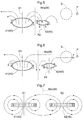
- FIG. 7 shows an example of a case in which a magnetic wall Wm is formed as the symmetric plane W
- FIG. 8 shows an example of a case in which an electric wall We is formed as the symmetric plane W.
- the magnetic field is orthogonal in the case of the magnetic wall Wm, as shown in FIG. 7 , and is parallel in the case of the electric wall We, as shown in FIG. 8 .
- the directions in which the magnetic and electric fields act are offset by 90°; therefore, although not shown, the electric field is parallel in the case of the magnetic wall Wm and is orthogonal in the case of the electric wall We.
- the phase of the AC current flowing through the auxiliary coil 42 is in an opposite-phase state, which is opposite the phase of the harmonic component in an AC current flowing through the main coil 41, under the first condition (magnetic wall condition) in which a magnetic wall Wm is formed.
- the difference in phase between the phase of the AC current flowing through the main coil 41 and the phase of the AC current flowing through the auxiliary coil 42 is not limited to being exactly 180°; a certain degree of shifting is permitted.
- the opposite-phase state may be any state in which, as viewed from a direction along the first reference axis X1, the harmonic component AC currents flowing through the conducting wire of the main coil 41 and the conducting wire of the auxiliary coil 42 are oriented in different directions when the harmonic components exhibit positive and negative peaks (peaks and troughs).
- the difference in phase preferably is approximately 180° ⁇ less than 45° (135° ⁇ difference in phase ⁇ 225°). As shall be apparent, a difference in phase of 180° is most preferable.
- the auxiliary resonance circuit 5c preferably is configured so as to satisfy the first condition (magnetic wall condition), in which a magnetic wall Wm is formed, when the main coil 41 and the auxiliary coil 42 are arranged adjacent to each other such that the reference axes are parallel to each other.
- the auxiliary coil 42 is arranged at a position in which an induction current is produced by a magnetic field produced by the electric current flowing through the main coil 41. Furthermore, the auxiliary coil 42 is configured in a state in which a frequency deviating by a predefined amount in a predefined direction from a target frequency predefined within a harmonic component of the fundamental component of an electromagnetic wave produced by the electric current flowing through the main coil 41 is taken as a resonance frequency, and constitutes the auxiliary resonance circuit 5c.
- the experiments and simulations performed by the inventor(s) indicate that the resonance frequency fc of the auxiliary resonance circuit 5c preferably is determined as described below.
- FIG. 9 shows an example of an embodiment in which the main coil 41 and the auxiliary coil 42 are concentrically arranged on substantially the same plane, in a state in which the reference axes are parallel to each other.
- the auxiliary coil 42 is arranged within the main coil 41, and an electric wall We is formed as the symmetric plane W.
- the term "concentric” used here may refer to a circumstance in which the auxiliary coil 42 is arranged within the main coil 41, or a circumstance in which the main coil 41 is arranged within the auxiliary coil 42, it not being essential for the first reference axis X1 and the second reference axis X2 to coincide.
- the frequency characteristics differ from those in the embodiment shown in FIG. 4 , and characteristics such as are shown in FIG. 10 are exhibited.
- the frequency characteristics of the rate at which noise is emitted from the main resonance circuit 5p shows a minimal value under the second condition (at the frequency f2), and shows a maximal value under the first condition (at the frequency f4). Therefore, it is preferable to set the resonance frequency fc of the auxiliary resonance circuit 5c so that the frequency of the electromagnetic wave generated by the main resonance circuit 5p has the second extreme frequency f2.
- the auxiliary coil 42 is preferably configured in a state in which a frequency deviating by a predefined amount (e.g., "fs") in a predefined direction (e.g., the direction along which the frequency decreases) from a target frequency (e.g., "f2”) predefined within a harmonic component of the fundamental component of the electromagnetic wave produced by the electric current flowing through the main coil 41 is taken as the resonance frequency fc.
- a frequency deviating by a predefined amount e.g., "fs”
- a predefined direction e.g., the direction along which the frequency decreases
- a target frequency e.g., "f2”
- the phase of the AC current flowing through the auxiliary coil 42 is in an opposite-phase state, which is opposite the phase of the harmonic component in an AC current flowing through the main coil 41.
- the opposite-phase state is a state in which, as viewed from a direction along the first reference axis X1, the harmonic component AC currents flowing through the conducting wire of the main coil 41 and the conducting wire of the auxiliary coil 42 are oriented in different directions when the harmonic components exhibit positive and negative peaks (peaks and troughs).
- the resonance frequency fc of the auxiliary resonance circuit 5c is determined as described below.
- the arrangement is substantially the same as in steps (S1)-(S4) described above, but because the direction of deviation is a reversed positive-negative direction, formulae (1) and (2) in step (S3) are replaced with formulae (4) and (5) below.
- FIG. 9 shows an example of an embodiment in which the auxiliary coil 42 is arranged within the main coil 41, as an embodiment in which the main coil 41 and the auxiliary coil 42 are concentrically arranged in a state in which the reference axes are parallel to each other.
- the main coil 41 is arranged within the auxiliary coil 42, as shown in FIG. 11
- the main coil 41 and the auxiliary coil 42 are concentrically arranged on substantially the same plane in a state in which the reference axes are parallel to each other.
- An electric wall We is formed in this case as well, as shown in FIG. 11 .
- the present invention is not limited to being applied to a vehicle.
- the present invention can be applied to the transmission of electric power generated by small-scale hydroelectric power generation, photovoltaic power generation, or small-scale wind-power generation to an ordinary house or building; specifically, the present invention can be used for power transmission in a smart grid system.
- the countermeasure against noise using the auxiliary resonance circuit 5c is not limited to being applied to power transmission; this countermeasure can be used to reduce noise in, e.g., an electromagnetic cooking device or various other systems or devices in which a coil generates noise.
- the present invention can be applied to an antenna coil unit for transmitting electric power or the like.
Landscapes
- Engineering & Computer Science (AREA)
- Power Engineering (AREA)
- Transportation (AREA)
- Mechanical Engineering (AREA)
- Computer Networks & Wireless Communication (AREA)
- Life Sciences & Earth Sciences (AREA)
- Sustainable Development (AREA)
- Sustainable Energy (AREA)
- Physics & Mathematics (AREA)
- Electromagnetism (AREA)
- Electric Propulsion And Braking For Vehicles (AREA)
- Charge And Discharge Circuits For Batteries Or The Like (AREA)
Abstract
Description
- The present invention relates to an antenna coil unit for transmitting electric power or the like.
- Cellular phones, personal digital assistants (PDAs), power-assisted bicycles, electric vehicles, hybrid vehicles, and other electrical devices and electromechanical apparatuses that are transportable without being left in one location have internal cells and other power storage devices so as to be capable of operating without being supplied by an external power supply. In many cases, charging of a power storage device is performed via a connection between a charge port provided to the device or apparatus and a power-supply device, interposed by a cable or the like. However, in recent years, there has been a demand for a technique for supplying electric power wirelessly without using such a cable, that is, without contact. In one technique for supplying electric power without contact, electromagnetic resonance coupling (referred to merely as "magnetic field resonance" below where appropriate) may be used. Magnetic field resonance is a technique in which a pair of resonance circuits having a natural frequency (resonance frequency) in common, e.g., a resonance circuit on the power-supplying equipment and a resonance circuit on the device or apparatus, are caused to resonate via a magnetic field, and electric power is transmitted via the magnetic field.
Japanese Laid-open Patent Application No. 2011-234496 - However, when power is supplied via magnetic field resonance, a magnetic field produced around a coil unit including a resonance coil (antenna coil) provided to the resonance circuit, the resonance coil serving as an antenna, may produce electromagnetic noise. Electronic equipment or the like arranged around the coil unit may thereby be affected by the electromagnetic noise. For example, in power supply to a vehicle, it is possible for audible noise to be produced in on-board audio. Additionally, if a conductor made of metal or another such material is present within the magnetic field, it is possible for the conductor to be heated due to the electromagnetic noise. For example, when a coil unit is installed in the bottom part of a vehicle, metal components in the bottom part of the vehicle may be heated. Therefore, a technique for suppressing such electromagnetic noise is required. The coil unit disclosed in
Patent Document 1 includes a plurality of resonance coils, the resonance coils being arranged so that the magnetic field produced in one resonance coil and the magnetic field produced in at least one other resonance coil are in opposite phases with regard to each other. This counterbalances the magnetic fields in areas beyond the resonance circuits and reduces magnetic field leakage (paragraphs 5-12, etc.). However, because the magnetic fields are counterbalanced, the strength of the magnetic field when the same electric power is imparted to the power-supply-side resonance coil is reduced, and the efficiency of power supply is also reduced. Because the resonance frequencies of the plurality of coils are set to the same value, harmonic noise is inadequately suppressed. -
Japanese Laid-open Patent Application No. 2012-115069 Patent Document 2, the antenna coil is configured so that the magnetic flux generated by the flat coil can be counterbalanced by the loop coil.Patent Document 2 indicates that, when an electric current is passed through the flat coil, it is only when the frequency corresponding to the electric current matches the resonance frequency of the resonance circuit that includes the loop coil that the loop coil will be magnetized by electromagnetic induction, so that magnetic flux in a direction opposite that of the magnetic flux generated by the flat coil will be generated. Specifically, inPatent Document 2, the resonance frequency of the resonance circuit that includes the noise-canceling loop coil is made to match the frequency of the noise to be canceled, whereby noise is reduced (paragraph 39, etc.). However, in, e.g., wireless power transmission by magnetic field resonance, a pronounced noise-reduction effect is not necessarily obtained even when the frequency of the noise source and the resonance frequency of the noise-canceling resonance circuit are made to match in this manner; this problem is becoming apparent in the experiments, etc. performed by the inventor(s). -
- Patent Document 1 :
Japanese Laid-open Patent Application No. 2011-234496 - Patent Document 2 :
Japanese Laid-open Patent Application No. 2012-115069 - In view of the foregoing, there has been a need for a technique in which noise components such as harmonic components of the fundamental component of an electromagnetic wave produced by an electric current flowing through a main coil that functions as an antenna is suppressed while the attenuation of the fundamental component is minimized.
- An antenna coil unit according to the present invention designed in view of the abovementioned problem includes:
- a main coil configured by winding a conducting wire around a first reference axis; and
- an auxiliary coil configured by winding a conducting wire around a second reference axis in a state of being electrically insulated from the main coil, the auxiliary coil being arranged at a position in which an induction current is produced by a magnetic field produced by an electric current flowing through the main coil;
- the auxiliary coil being configured in a state in which a frequency deviating by a predefined amount in a predefined direction from a target frequency predefined within a harmonic component of the fundamental component in an electromagnetic wave produced by the electric current flowing through the main coil is taken as a resonance frequency; and
- the direction and amount being such that the phase of an alternating-current (AC) current flowing through the auxiliary coil is in an opposite-phase state, which is opposite the phase of the harmonic component in an AC current flowing through the main coil.
- The term "opposite-phase state" used here refers to a state in which the difference in phase between the phase of the AC current flowing through the main coil and the phase of the AC current flowing through the auxiliary coil equals 180° ± less than 90° (90° < difference in phase < 270°).
- When the antenna coil unit is configured in this manner, the magnetic flux of the frequency component including the noise component, within the magnetic flux produced by the electric current flowing through the main coil, is drawn into the auxiliary coil and then returned to the main coil via the auxiliary coil. Specifically, the magnetic flux of the noise component generated by the main coil advances toward the auxiliary coil, which is arranged near enough that an induction current is produced due to the magnetic flux, without advancing a long distance. As a result, it is possible to suppress noise components located a long distance from the auxiliary coil as viewed from the main coil. The inspections, experiments, simulations, etc. performed by the inventor(s) have confirmed that a more pronounced noise-suppression effect is achieved when the resonance frequency of the auxiliary coil is set to a frequency that is shifted to a certain extent from the frequency of the noise component to be suppressed, rather than to the frequency of the noise component to be suppressed. The noise component having the most pronounced impact is often a harmonic component of the fundamental component of an electromagnetic wave produced by the electric current flowing through the main coil; the resonance frequency of the auxiliary coil preferably is a frequency that deviates from the harmonic component under predefined conditions. Thus, with the antenna coil unit according to the present invention, it is possible to suppress a noise component such as a harmonic component of the fundamental component of an electromagnetic wave produced by an electric current flowing through a main coil that functions as an antenna while minimizing the attenuation of the fundamental component.
- Examples of preferred embodiments of the present invention will be described below.
- In the antenna coil unit according to the present invention, as an example of one embodiment, the first reference axis and the second reference axis are preferably parallel. When the first reference axis and the second reference axis are parallel, the main coil and the auxiliary coil can be arranged on substantially the same plane; therefore, increases in the size of the antenna coil unit can be minimized.
- In the antenna coil unit according to the present invention, it is preferable to use, e.g., electromagnetic resonance coupling (referred to merely as "magnetic field resonance" below where appropriate) and to apply electromagnetic resonance coupling to a device for transmitting electric power without contact. Specifically, as an example of one embodiment, the main coil of the antenna coil unit according to the present invention can be applied as a primary coil constituting a power-supply circuit and/or as a secondary coil constituting a power-receiving circuit in a power-supply device for transmitting electric power from the power-supply circuit to the power-receiving circuit using electromagnetic resonance coupling.
- In order to produce the opposite-phase state described above, it is necessary for the harmonic component AC currents flowing through the conducting wire of the main coil and the conducting wire of the auxiliary coil to be oriented in different directions. As an example of a preferred embodiment, the opposite-phase state may be a state in which, as viewed from a direction along the first reference axis, the harmonic component AC currents flowing through the conducting wire of the main coil and the conducting wire of the auxiliary coil are oriented in different directions at the peaks of the harmonic components. The term "peak" used here refers to both positive- and negative-direction peaks (peaks and troughs) of the harmonic component. The phrase "a state in which ... the harmonic component AC currents ... are oriented in different directions at the peaks of the harmonic components" used here refers to a circumstance in which, when the phases of the peaks of the harmonic component AC current flowing through the conducting wire of the main coil and of the peaks of the harmonic component AC current flowing through the conducting wire of the auxiliary coil are shifted, the orientation of either one of the harmonic component AC currents is reversed at the peaks of the other harmonic component AC current. Most preferably, the phrase "a state in which ... the harmonic component AC currents ... are oriented in different directions" refers to a state in which the peaks of the harmonic component AC current flowing through the conducting wire of the main coil and the peaks of the harmonic component AC current flowing through the conducting wire of the auxiliary coil are in a relationship such that either one of the harmonic component AC currents has a negative-direction peak when the other of the harmonic component AC currents has a positive-direction peak.
-
-
FIG. 1 is a block diagram schematically showing the configuration of a wireless power-supply system; -
FIG. 2 is a representative circuit schematic of a resonance circuit; -
FIG. 3 is a representative circuit schematic of a resonance circuit unit; -
FIG. 4 is a diagram showing frequency characteristics of the transmission efficiency and the noise emission rate; -
FIG. 5 is a schematic diagram showing an example of the magnetic flux in an antenna coil unit when noise is being suppressed; -
FIG. 6 is a schematic diagram showing an example of the magnetic flux in an antenna coil unit when noise is not being suppressed; -
FIG. 7 is a schematic diagram showing the relationship between a magnetic field and an electric current under a magnetic wall condition; -
FIG. 8 is a schematic diagram showing the relationship between a magnetic field and an electric current under an electric wall condition; -
FIG. 9 is a schematic diagram showing another example of the magnetic flux in an antenna coil unit when noise is being suppressed; -
FIG. 10 is a diagram showing frequency characteristics of the transmission efficiency and the noise emission rate; and -
FIG. 11 is a schematic diagram showing a different example of the magnetic flux in an antenna coil unit when noise is being suppressed. - Embodiments of the present invention will be described below, as examples of a wireless power-supply system for using electromagnetic resonance coupling (referred to merely as "magnetic field resonance" below where appropriate) to perform wireless power supply (wireless power transmission) to a vehicle, with reference to the accompanying drawings. As shown in
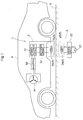
FIG. 1 , a wireless power-supply system 1 (magnetic-field-resonance-type power supply device) is configured from a power-supply system 2 installed in a power-supply facility, and a power-receivingsystem 3 mounted in avehicle 9. In the present embodiment, the power-supply system 2 is installed, e.g., near the ground G if the facility is outdoors, or near the floor if the facility is indoors. - As shown in
FIG. 1 , the power-supply system 2 is configured to have anAC power source 21, adriver circuit 22, and a power-supply-side resonance circuit 25. The power-supply-side resonance circuit 25 is configured to have a power-supply-side resonance coil 24. The power-receivingsystem 3 is configured to have a power-receiving-side resonance circuit 35, arectifier circuit 32, and apower storage device 31. The power-receiving-side resonance circuit 35 is configured to have a power-receiving-side resonance coil 34. The power-supply-side resonance circuit 25 and the power-receiving-side resonance circuit 35 are resonance circuits having the same natural frequency (resonance frequency), the tworesonance circuits resonance circuits 5." The power-supply-side resonance coil 24 and the power-receiving-side resonance coil 34 are referred to collectively as either "resonance coils" or "antenna coils 4." - The
AC power source 21 of the power-supply system 2 is, e.g., a power source (system power source) supplied from a commercial distribution network owned by a power company; the frequency of the AC power source is, e.g., 50 or 60 Hz. Thedriver circuit 22 is a circuit for converting the 50- or 60-Hz frequency of the system power source to the resonance frequency of the power-supply-side resonance circuit 25 (the resonance circuit 5), thedriver circuit 22 being configured from a high frequency power source circuit. Thepower storage device 31 of the power-receivingsystem 3 is a direct-current (DC) power source capable of being electrically charged and discharged, thepower storage device 31 using, e.g., a lithium-ion, nickel-metal-hydride, or other type of secondary cell, or a capacitor. The electric power received by the power-receiving-side resonance circuit 35 is AC power having the resonance frequency of the power-receiving-side resonance circuit 35. Therectifier circuit 32 rectifies the AC power having the resonance frequency to DC power. Thedriver circuit 22 and the power-supply-side resonance circuit 25 working in conjunction with each other, or the entire power-supply system 2, is comparable to a power-supply circuit in the broadest sense. The power-supply-side resonance circuit 25 is comparable to a power-supply circuit in a more limited sense. Similarly, the power-receiving-side resonance circuit 35 and therectifier circuit 32 working in conjunction [with each other], or the entire power-receivingsystem 3, is comparable to a power-receiving circuit in the broadest sense. The power-receiving-side resonance circuit 35 is comparable to a power-receiving circuit in a more limited sense. - The
vehicle 9 is, e.g., an electric vehicle driven by a rotatingelectrical machine 91, or a hybrid vehicle driven by an internal combustion engine (not shown) and a rotatingelectrical machine 91. The rotatingelectrical machine 91 is connected to thepower storage device 31 interposed by, e.g., aninverter 92 or other driver for a rotating electrical machine. In the present embodiment, the rotatingelectric machine 91 is, e.g., a three-phase AC rotating electrical machine, the driver for a rotating electrical machine being configured to have theinverter 92 for converting electric power to/from DC and AC as a core. The rotatingelectrical machine 91 can function as an electric motor and as a power generator. - The wireless power-supply system 1 (magnetic-field-resonance-type power supply device) is a system for causing the pair of resonance circuits 5 (25, 35) to resonate via a magnetic field, and transmitting power via the magnetic field. Magnetic resonance imaging (MRI), which is frequently used in the medical field, is known as a "resonance" technique using "magnetic properties"; however, whereas MRI uses the physical phenomenon of "magnetic-spin resonance," no such physical phenomenon is used in the "magnetic-field-resonance-type power supply device" of the present invention. In the "magnetic-field-resonance-type power supply device" of the present invention, as described above, two
resonance circuits 5 are caused to resonate via a "magnetic field." Therefore, the transmission scheme employed in the wireless power-supply system 1 for transmitting electric power using resonance in a magnetic field is referred to here as "electromagnetic resonance coupling" or "magnetic field resonance," taking into account its clear distinction from MRI. This method of transmission also differs from "electromagnetic induction." - As described above, the power-supply-
side resonance circuit 25 and the power-receiving-side resonance circuit 35 have the same natural frequency (resonance frequency). In the present embodiment, the power-supply-side resonance circuit 25 and the power-receiving-side resonance circuit 35 are LC resonators having the same configuration. Therefore, in the description below, the tworesonance circuits resonance circuits 5" when there is no need to distinguish between them. As shown in the representative circuit schematic inFIG. 2 , theresonance circuits 5 are configured to haveantenna coils 4 having inductance components "L," andcapacitors 6 having capacitance components "C." - The power-supply-
side resonance circuit 25 and the power-receiving-side resonance circuit 35 have the same resonance frequency. The power-supply-side resonance circuit 25 and the power-receiving-side resonance circuit 35 resonate together in the same way, for example, as when one of two tuning forks arranged so as to be set apart from each other is caused to vibrate in air, the other tuning fork resonating with the vibration transmitted via the air and vibrating. More specifically, the power-receiving-side resonance circuit 35 resonates (electromagnetically vibrates) with the resonance (electromagnetic vibration) transmitted thereto via the magnetic field produced by the electromagnetic vibration of the power-supply-side resonance circuit 25. - The wireless power-
supply system 1 preferably supplies power by highly efficient transmission while suppressing leakage of the magnetic flux to spaces other than the space formed by the magnetic fields coupling the power-supply-side and power-receiving-side resonance circuits 5. In order to realize this objective, the present invention is configured from aresonance circuit unit 50 including a resonance circuit additional to the resonance circuits 5 (anauxiliary resonance circuit 5c). Theauxiliary resonance circuit 5c operates to suppress the electromagnetic waves constituting the noise component. When a particular distinction is to be made with respect to the power-transmittingresonance circuits 5 in theresonance circuit units 50, the term "main resonance circuit 5p" is used to refer to the circuit that corresponds to theauxiliary resonance circuit 5c. As described below, antenna coils (main coil 41, auxiliary coil 42) constituting themain resonance circuit 5p and theauxiliary resonance circuit 5c, respectively, are provided to theresonance circuit unit 50 in a predefined relative arrangement. These antenna coils are collectively referred to here as anantenna coil unit 40. - As shown in
FIG. 3 , theresonance circuit unit 50 is configured to include themain resonance circuit 5p, which is configured to include themain coil 41, and theauxiliary resonance circuit 5c, which is configured to include theauxiliary coil 42. Themain coil 41 is configured by winding a conducting wire around a first reference axis X1 (seeFIGS. 5-8 ), and constitutes the resonance circuits 5 (main resonance circuit 5p) described above. Theauxiliary coil 42 is configured by winding a conducting wire around a second reference axis X2 (seeFIGS. 5-8 ) in a state of being electrically insulated from themain coil 41. Additionally, theauxiliary coil 42 is arranged at a position in which an induction current is produced by a magnetic field produced by the electric current flowing through themain coil 41. Theauxiliary coil 42 is configured in a state in which a frequency deviating by a predefined amount in a predefined direction from a target frequency predefined within a harmonic component of the fundamental component of an electromagnetic wave produced by the electric current flowing through themain coil 41 is taken as a resonance frequency (fc), and constitutes theauxiliary resonance circuit 5c described above. The direction and amount used here are such that the phase of an AC current flowing through theauxiliary coil 42 is in an opposite-phase state, which is opposite the phase of the harmonic component in the AC current flowing through themain coil 41. The "opposite-phase state" will be described below. - As described above, the main coil 41 (antenna coil 4) of the
main resonance circuit 5p (resonance circuits 5) functions as a transmitting/receiving antenna of the wireless power-supply system 1. Specifically, in the power-supply device (wireless power-supply system 1) for transmitting electric power from the power-supply circuit (power-supply system 2) to the power-receiving circuit (power-receiving system 3) using electromagnetic resonance coupling, themain coil 41 functions as a primary coil constituting the power-supply circuit and/or as a secondary coil constituting the power-receiving circuit. Themain resonance circuit 5p generates an electromagnetic field of a resonance frequency defined by themain coil 41 having an inductance component "Lp," and acapacitor 61 having a capacitance component "Cp." Alternatively, an electric current may be passed through the main coil 41 (antenna coil 4) by the action of an electromagnetic field of this resonance frequency. - Conversely, a resonance frequency (fc) of the
auxiliary resonance circuit 5c, is defined by theauxiliary coil 42, which has an inductance component "Ln," and acapacitor 62, which has a capacitance component "Cn." This resonance frequency differs from the resonance frequency of themain resonance circuit 5p; theauxiliary resonance circuit 5c does not contribute to the transmission of electric power. The resonance frequency of theauxiliary resonance circuit 5c is set on the basis of the harmonic component of the fundamental component in the resonance frequency of themain resonance circuit 5p. The harmonic component, e.g., a fifth-order, seventh-order, ninth-order, or other high-order harmonic component, may act on other devices or the like as a noise component. Theauxiliary resonance circuit 5c is a noise-canceling resonance circuit that acts so as to cause the electromagnetic wave of the noise component produced by the electromagnetic field generated by themain resonance circuit 5p to attenuate. The symbol "Lm" inFIG. 3 signifies the relative inductance between themain coil 41 and theauxiliary coil 42. - A terminal pair t1 of the
main resonance circuit 5p is connected to thedriver circuit 22 or therectifier circuit 32, as shown inFIG. 1 . Conversely, a terminal pair t2 of theauxiliary resonance circuit 5c are connected to each other to form a closed circuit; the terminal pair t2 resonates with the electromagnetic wave generated by themain resonance circuit 5p, whereby an electric current flows within the closed circuit. In the description below, circuit characteristics are described as performing power transmission from themain resonance circuit 5p to theauxiliary resonance circuit 5c. The sharpness "Q" of the resonance of themain resonance circuit 5p and theauxiliary resonance circuit 5c is "50" or higher, and preferably increases the transmission efficiency. -
FIG. 4 shows the frequency characteristics of the transmission efficiency (solid line) and the noise emission rate (chained line) in a power transmission circuit such as is shown inFIG. 3 , the power transmission circuit being formed when themain coil 41 and theauxiliary coil 42 are arranged adjacent to each other, as shown inFIGS. 5 and 6 . As shown inFIG. 4 , two frequencies corresponding to extreme values are present in the transmission efficiency. The lower of these two frequencies is referred to as a first extreme frequency f1, and the higher of the two frequencies is referred to as a second extreme frequency f2. The symbol "fc" inFIG. 4 indicates the resonance frequency of theauxiliary resonance circuit 5c. - At the first extreme frequency f1, the
main resonance circuit 5p and theauxiliary resonance circuit 5c are coupled under a first condition in which a magnetic field is produced by the flowing of an electric current (I), as shown inFIG. 5 . A point P indicates a point set apart from the space in which the magnetic field coupling the power-supply-side and power-receiving-side resonance circuits 5 is formed. The magnetic flux from themain coil 41 inFIG. 5 is directed toward theauxiliary coil 42; therefore, magnetic flux approaching the vicinity of the point P (e.g., a region S) is suppressed. Specifically, the noisy electromagnetic wave due to the harmonic component of the fundamental component of the electromagnetic wave produced by the electric current flowing through themain coil 41 is suppressed. - Conversely, at a frequency "f3" between the resonance frequency fc of the
auxiliary resonance circuit 5c and the second extreme frequency f2, themain resonance circuit 5p and theauxiliary resonance circuit 5c are coupled under a second condition in which a magnetic field is formed by the flowing of an electric current (I), as shown inFIG. 6 . InFIG. 6 , the magnetic flux from themain coil 41 and the magnetic flux from theauxiliary coil 42 are directed in the same direction; therefore, these fluxes readily reach the point P. The magnetic flux in the vicinity of the point P (in the region S) is different in the case of the first condition (FIG. 5 ), and is directed in the same direction as the magnetic flux from themain coil 41; therefore, the magnetic flux in the vicinity of the point P is strengthened to a greater extent than when noauxiliary coil 42 is provided. Specifically, the noisy electromagnetic wave produced by the harmonic component of the fundamental component of the electromagnetic wave produced by the electric current flowing through themain coil 41 is strengthened. - Specifically, as shown in
FIG. 4 , the frequency characteristic of the noise emission rate (chained line) from themain resonance circuit 5p shows a minimal value under the first condition (at the frequency f1), and shows a maximal value under the second condition (at the frequency f3). Therefore, it is preferable to set the resonance frequency fc of theauxiliary resonance circuit 5c so that the frequency of the electromagnetic wave having a noise component generated by themain resonance circuit 5p has the first extreme frequency f1. Specifically, theauxiliary coil 42 is preferably configured in a state in which a frequency deviating by a predefined amount (e.g., "fs") in a predefined direction (e.g., the direction along which the frequency increases) from a target frequency (e.g., "f1") predefined within a harmonic component of the fundamental component of the electromagnetic wave produced by the electric current flowing through themain coil 41 is taken as the resonance frequency fc. - When the
main coil 41 and theauxiliary coil 42 are arranged adjacent to each other on substantially the same plane, as inFIGS. 5 and 6 , the first condition can be referred to as a "magnetic wall condition," under which a symmetric plane W between themain coil 41 and theauxiliary coil 42 is referred to as a "magnetic wall." Additionally, the second condition can be referred to as an "electric wall condition," under which the symmetric plane W between themain coil 41 and theauxiliary coil 42 is referred to as an "electric wall." The term "symmetric plane W" used here refers to a plane provided at a position so as to divide the space between the region in which themain coil 41 is arranged and the region in which theauxiliary coil 42 is arranged. Specifically, the symmetric plane W is a plane set so that the region in which themain coil 41 is arranged and the region in which theauxiliary coil 42 is arranged are symmetrically arranged on either side of the symmetric plane W. Due to their being described in detail in "Takehiro Imura, Yoichi Hori: "Wireless Power Transfer Using Electromagnetic Resonant Coupling" IEEJ Journal Vol. 129, No. 7, 2009," the concepts behind magnetic walls and electric walls will instead be described somewhat more generically below. -
FIG. 7 shows an example of a case in which a magnetic wall Wm is formed as the symmetric plane W, andFIG. 8 shows an example of a case in which an electric wall We is formed as the symmetric plane W. The magnetic field is orthogonal in the case of the magnetic wall Wm, as shown inFIG. 7 , and is parallel in the case of the electric wall We, as shown inFIG. 8 . The directions in which the magnetic and electric fields act are offset by 90°; therefore, although not shown, the electric field is parallel in the case of the magnetic wall Wm and is orthogonal in the case of the electric wall We. - As shown in
FIG. 7 , when themain coil 41 and theauxiliary coil 42 are arranged adjacent to each other on substantially the same plane, the phase of the AC current flowing through theauxiliary coil 42 is in an opposite-phase state, which is opposite the phase of the harmonic component in an AC current flowing through themain coil 41, under the first condition (magnetic wall condition) in which a magnetic wall Wm is formed. In the opposite-phase state, the difference in phase between the phase of the AC current flowing through themain coil 41 and the phase of the AC current flowing through theauxiliary coil 42 is not limited to being exactly 180°; a certain degree of shifting is permitted. The magnetic wall condition is not established when the difference in phase is 180° ± 90°; therefore, a range of 180° ± less than 90° (90° < difference in phase < 270°) is physically permitted. Specifically, the opposite-phase state may be any state in which, as viewed from a direction along the first reference axis X1, the harmonic component AC currents flowing through the conducting wire of themain coil 41 and the conducting wire of theauxiliary coil 42 are oriented in different directions when the harmonic components exhibit positive and negative peaks (peaks and troughs). However, in consideration of the noise-suppression effect, the difference in phase preferably is approximately 180° ± less than 45° (135° < difference in phase < 225°). As shall be apparent, a difference in phase of 180° is most preferable. - As shown in
FIGS. 5 and 7 , theauxiliary resonance circuit 5c preferably is configured so as to satisfy the first condition (magnetic wall condition), in which a magnetic wall Wm is formed, when themain coil 41 and theauxiliary coil 42 are arranged adjacent to each other such that the reference axes are parallel to each other. - As described above, the
auxiliary coil 42 is arranged at a position in which an induction current is produced by a magnetic field produced by the electric current flowing through themain coil 41. Furthermore, theauxiliary coil 42 is configured in a state in which a frequency deviating by a predefined amount in a predefined direction from a target frequency predefined within a harmonic component of the fundamental component of an electromagnetic wave produced by the electric current flowing through themain coil 41 is taken as a resonance frequency, and constitutes theauxiliary resonance circuit 5c. The experiments and simulations performed by the inventor(s) indicate that the resonance frequency fc of theauxiliary resonance circuit 5c preferably is determined as described below. -
- (S1) The primary-side (power-supply-side resonance circuit 25) and secondary-side (power-receiving-side resonance circuit 35) terminal pairs t1 are opened/short-circuited, whereby the degree of coupling "K" as viewed from the
auxiliary resonance circuit 5c is measured. - (S2) The relative impedance Lm of the main coil 41 (e.g., the primary-side main coil) and the
auxiliary coil 42 is determined (Lm = K · Ln). - (S3) On the basis of formula (1) below, the value Cn of the
capacitor 62 for the harmonic frequency to be attenuated is calculated (formula (2)).

- (S4) Using formula (3) below, the set frequency (resonance frequency fc) of the
auxiliary resonance circuit 5c is calculated. The circuit constants (Ln, Cn) of theauxiliary resonance circuit 5c are already determined in step (S3) above; therefore, from a practical standpoint, it is unnecessary to compute the resonance frequency fc.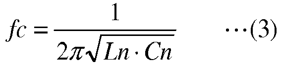
- In the example described above, the
auxiliary coil 42 was arranged so as to satisfy the magnetic wall condition, and theauxiliary resonance circuit 5c was configured using theauxiliary coil 42. However, this embodiment is not provided by way of limitation; it is also possible to suppress noise by arranging theauxiliary coil 42 so as to satisfy the electric wall condition. Such an embodiment is described below.FIG. 9 shows an example of an embodiment in which themain coil 41 and theauxiliary coil 42 are concentrically arranged on substantially the same plane, in a state in which the reference axes are parallel to each other. InFIG. 9 , theauxiliary coil 42 is arranged within themain coil 41, and an electric wall We is formed as the symmetric plane W. The term "concentric" used here may refer to a circumstance in which theauxiliary coil 42 is arranged within themain coil 41, or a circumstance in which themain coil 41 is arranged within theauxiliary coil 42, it not being essential for the first reference axis X1 and the second reference axis X2 to coincide. - However, under such circumstances, the frequency characteristics differ from those in the embodiment shown in
FIG. 4 , and characteristics such as are shown inFIG. 10 are exhibited. The frequency characteristics of the rate at which noise is emitted from themain resonance circuit 5p (chained line) shows a minimal value under the second condition (at the frequency f2), and shows a maximal value under the first condition (at the frequency f4). Therefore, it is preferable to set the resonance frequency fc of theauxiliary resonance circuit 5c so that the frequency of the electromagnetic wave generated by themain resonance circuit 5p has the second extreme frequency f2. Specifically, theauxiliary coil 42 is preferably configured in a state in which a frequency deviating by a predefined amount (e.g., "fs") in a predefined direction (e.g., the direction along which the frequency decreases) from a target frequency (e.g., "f2") predefined within a harmonic component of the fundamental component of the electromagnetic wave produced by the electric current flowing through themain coil 41 is taken as the resonance frequency fc. - Even in the embodiment shown in
FIG. 9 , when the condition under which the electromagnetic waves having a noise component are reduced (referred to here as "the second condition" (electric wall condition)) is satisfied, the phase of the AC current flowing through theauxiliary coil 42 is in an opposite-phase state, which is opposite the phase of the harmonic component in an AC current flowing through themain coil 41. Specifically, the opposite-phase state is a state in which, as viewed from a direction along the first reference axis X1, the harmonic component AC currents flowing through the conducting wire of themain coil 41 and the conducting wire of theauxiliary coil 42 are oriented in different directions when the harmonic components exhibit positive and negative peaks (peaks and troughs). - In this case, the resonance frequency fc of the
auxiliary resonance circuit 5c is determined as described below. The arrangement is substantially the same as in steps (S1)-(S4) described above, but because the direction of deviation is a reversed positive-negative direction, formulae (1) and (2) in step (S3) are replaced with formulae (4) and (5) below.

-
FIG. 9 shows an example of an embodiment in which theauxiliary coil 42 is arranged within themain coil 41, as an embodiment in which themain coil 41 and theauxiliary coil 42 are concentrically arranged in a state in which the reference axes are parallel to each other. However, it is also possible to adopt an embodiment in which themain coil 41 is arranged within theauxiliary coil 42, as shown inFIG. 11 , as an embodiment in which themain coil 41 and theauxiliary coil 42 are concentrically arranged on substantially the same plane in a state in which the reference axes are parallel to each other. An electric wall We is formed in this case as well, as shown inFIG. 11 . There is no change to the fact that the phases of the AC current flowing through themain coil 41 and the AC current flowing through theauxiliary coil 42 are reversed, nor to the method for determining the resonance frequency fc; therefore, these features are not repeated here. - In the embodiments described above, examples were illustrated in which a power storage device mounted in a
vehicle 9 was wirelessly powered; however, as shall be apparent, the present invention is not limited to being applied to a vehicle. For example, the present invention can be applied to the transmission of electric power generated by small-scale hydroelectric power generation, photovoltaic power generation, or small-scale wind-power generation to an ordinary house or building; specifically, the present invention can be used for power transmission in a smart grid system. Additionally, the countermeasure against noise using theauxiliary resonance circuit 5c (noise-canceling resonance circuit) is not limited to being applied to power transmission; this countermeasure can be used to reduce noise in, e.g., an electromagnetic cooking device or various other systems or devices in which a coil generates noise. - The present invention can be applied to an antenna coil unit for transmitting electric power or the like.
-
- 1
- Wireless power-supply system (power-supply device)
- 2
- Power-supply system (power-supply circuit)
- 3
- Power-receiving system (power-receiving circuit)
- 4
- Antenna coil
- 5
- Resonance circuit
- 5c
- Auxiliary resonance circuit
- 5p
- Main resonance circuit
- 40
- Antenna coil unit
- 41
- Main coil
- 42
- Auxiliary coil
- X1
- First reference axis
- X2
- Second reference axis
- f1
- First extreme frequency
- f2
- Second extreme frequency
- fc
- Resonance frequency
Claims (4)
- An antenna coil unit comprising:a main coil configured by winding a conducting wire around a first reference axis; andan auxiliary coil configured by winding a conducting wire around a second reference axis in a state of being electrically insulated from the main coil, the auxiliary coil being arranged at a position in which an induction current is produced by a magnetic field produced by an electric current flowing through the main coil;the auxiliary coil being configured in a state in which a frequency deviating by a predefined amount in a predefined direction from a target frequency predefined within a harmonic component of the fundamental component of an electromagnetic wave produced by the electric current flowing through the main coil is taken as a resonance frequency; andthe direction and amount being such that the phase of an alternating-current (AC) current flowing through the auxiliary coil is in an opposite-phase state, which is opposite the phase of the harmonic component in an AC current flowing through the main coil.
- The antenna coil unit of claim 1, wherein the first reference axis and the second reference axis are parallel.
- The antenna coil unit of claim 1 or 2, wherein the main coil is a primary coil constituting a power-supply circuit and/or a secondary coil constituting a power-receiving circuit in a power-supply device for transmitting electric power from the power-supply circuit to the power-receiving circuit using electromagnetic resonance coupling.
- The antenna coil unit of any of claims 1-3, wherein the opposite-phase state is a state in which, as viewed from a direction along the first reference axis, the harmonic component AC currents flowing through the conducting wire of the main coil and the conducting wire of the auxiliary coil are oriented in different directions at the peaks of the harmonic components.
Applications Claiming Priority (2)
| Application Number | Priority Date | Filing Date | Title |
|---|---|---|---|
| JP2013136529A JP6142413B2 (en) | 2013-06-28 | 2013-06-28 | Antenna coil unit |
| PCT/JP2014/067128 WO2014208715A1 (en) | 2013-06-28 | 2014-06-27 | Antenna coil unit |
Publications (2)
| Publication Number | Publication Date |
|---|---|
| EP3016243A1 true EP3016243A1 (en) | 2016-05-04 |
| EP3016243A4 EP3016243A4 (en) | 2017-03-01 |
Family
ID=52142040
Family Applications (1)
| Application Number | Title | Priority Date | Filing Date |
|---|---|---|---|
| EP14818672.9A Withdrawn EP3016243A4 (en) | 2013-06-28 | 2014-06-27 | Antenna coil unit |
Country Status (5)
| Country | Link |
|---|---|
| US (1) | US9991047B2 (en) |
| EP (1) | EP3016243A4 (en) |
| JP (1) | JP6142413B2 (en) |
| CN (1) | CN104662774B (en) |
| WO (1) | WO2014208715A1 (en) |
Families Citing this family (13)
| Publication number | Priority date | Publication date | Assignee | Title |
|---|---|---|---|---|
| US20180278079A1 (en) * | 2012-01-11 | 2018-09-27 | Wheel Charge Technologies LLC | Apparatus for Wireless Power Transmission Between an External Power Source and an Electric Mobility Vehicle |
| JP6407401B2 (en) * | 2015-02-25 | 2018-10-17 | 株式会社東芝 | Resonator and wireless power transmission device |
| JP2017011844A (en) * | 2015-06-19 | 2017-01-12 | 株式会社日本自動車部品総合研究所 | Power transmission auxiliary device and wireless power feeding system |
| WO2017187610A1 (en) * | 2016-04-28 | 2017-11-02 | 三菱電機エンジニアリング株式会社 | Resonance-type power transmission device |
| JP6522546B2 (en) | 2016-05-12 | 2019-05-29 | マクセル株式会社 | Power coil |
| JP6538628B2 (en) * | 2016-09-05 | 2019-07-03 | 株式会社東芝 | Filter circuit and wireless power transmission system |
| JP6819476B2 (en) * | 2017-06-16 | 2021-01-27 | トヨタ自動車株式会社 | Vehicle front structure |
| CN111630721B (en) | 2018-01-22 | 2022-08-30 | 京瓷株式会社 | Repeater |
| US11896843B2 (en) * | 2018-01-24 | 2024-02-13 | National University Of Singapore | Photodynamic therapy devices, systems and methods |
| US11831082B2 (en) | 2018-08-24 | 2023-11-28 | Kyocera Corporation | Structure, antenna, wireless communication module, and wireless communication device |
| EP3843210A4 (en) | 2018-08-24 | 2022-04-27 | Kyocera Corporation | STRUCTURE, ANTENNA, WIRELESS COMMUNICATIONS MODULE AND WIRELESS COMMUNICATIONS DEVICE |
| WO2021014831A1 (en) * | 2019-07-25 | 2021-01-28 | 株式会社デンソー | Contactless power supply system |
| JP7712618B2 (en) * | 2021-10-05 | 2025-07-24 | アクト電子株式会社 | Insulation/short circuit switching device for insulated wheels, track maintenance vehicle, and insulation/short circuit switching method for insulated wheels |
Family Cites Families (8)
| Publication number | Priority date | Publication date | Assignee | Title |
|---|---|---|---|---|
| JP4985850B2 (en) | 2008-07-04 | 2012-07-25 | 村田機械株式会社 | Traveling vehicle system |
| JP4911148B2 (en) * | 2008-09-02 | 2012-04-04 | ソニー株式会社 | Contactless power supply |
| JP5434330B2 (en) * | 2009-07-22 | 2014-03-05 | ソニー株式会社 | Power receiving device, power transmission system, charging device, and power transmission method |
| JP5526796B2 (en) * | 2010-01-15 | 2014-06-18 | ソニー株式会社 | Wireless power supply rack |
| JP5139469B2 (en) * | 2010-04-27 | 2013-02-06 | 株式会社日本自動車部品総合研究所 | Coil unit and wireless power supply system |
| US8310202B2 (en) * | 2010-08-17 | 2012-11-13 | Ut-Battelle, Llc | Off-resonance frequency operation for power transfer in a loosely coupled air core transformer |
| JP2012115069A (en) * | 2010-11-25 | 2012-06-14 | Nec Tokin Corp | Antenna, power transmission device, power reception device, and non-contact communication device |
| JP5967374B2 (en) | 2013-01-31 | 2016-08-10 | 株式会社エクォス・リサーチ | Noise canceling resonator |
-
2013
- 2013-06-28 JP JP2013136529A patent/JP6142413B2/en not_active Expired - Fee Related
-
2014
- 2014-06-27 US US14/428,387 patent/US9991047B2/en active Active
- 2014-06-27 CN CN201480002465.9A patent/CN104662774B/en not_active Expired - Fee Related
- 2014-06-27 WO PCT/JP2014/067128 patent/WO2014208715A1/en not_active Ceased
- 2014-06-27 EP EP14818672.9A patent/EP3016243A4/en not_active Withdrawn
Non-Patent Citations (1)
| Title |
|---|
| See references of WO2014208715A1 * |
Also Published As
| Publication number | Publication date |
|---|---|
| CN104662774A (en) | 2015-05-27 |
| WO2014208715A1 (en) | 2014-12-31 |
| US20150235761A1 (en) | 2015-08-20 |
| JP2015012702A (en) | 2015-01-19 |
| JP6142413B2 (en) | 2017-06-07 |
| EP3016243A4 (en) | 2017-03-01 |
| CN104662774B (en) | 2017-03-08 |
| US9991047B2 (en) | 2018-06-05 |
Similar Documents
| Publication | Publication Date | Title |
|---|---|---|
| US9991047B2 (en) | Antenna coil unit | |
| JP5139469B2 (en) | Coil unit and wireless power supply system | |
| EP2555375B1 (en) | Voltage detector, malfunction detecting device, contactless power transmitting device, contactless power receiving device, and vehicle | |
| KR101750149B1 (en) | Vehicle | |
| JP5867511B2 (en) | Power transmission device, power reception device, and power transmission system | |
| US20160355094A1 (en) | Power receiving system | |
| JP6028000B2 (en) | Power transmission system | |
| CN103347730A (en) | Vehicle and external power-feeding apparatus | |
| EP2854146B1 (en) | Non-contact power supply transformer | |
| JP2015015852A (en) | Coil antenna | |
| US20150061402A1 (en) | Power reception device, power transmission device and power transfer system | |
| US9721722B2 (en) | Power reception device, vehicle including power reception device, and power transfer system | |
| CN104969441B (en) | noise canceling resonator | |
| Ahn et al. | Wireless power transmitter and receiver supporting 200-kHz and 6.78-MHz dual-band operation without magnetic field canceling | |
| JP6040397B2 (en) | Power transmission system | |
| JP6085813B2 (en) | Power transmission system | |
| JP6085811B2 (en) | Power transmission system | |
| JP2014197932A (en) | Power transmission system | |
| JP2017093141A (en) | Contactless power transmission equipment | |
| JP6085812B2 (en) | Power transmission system | |
| JP2017093142A (en) | Contactless power transmission equipment | |
| JP2015065341A (en) | Antenna coil and power transmission system |
Legal Events
| Date | Code | Title | Description |
|---|---|---|---|
| PUAI | Public reference made under article 153(3) epc to a published international application that has entered the european phase |
Free format text: ORIGINAL CODE: 0009012 |
|
| 17P | Request for examination filed |
Effective date: 20150319 |
|
| AK | Designated contracting states |
Kind code of ref document: A1 Designated state(s): AL AT BE BG CH CY CZ DE DK EE ES FI FR GB GR HR HU IE IS IT LI LT LU LV MC MK MT NL NO PL PT RO RS SE SI SK SM TR |
|
| AX | Request for extension of the european patent |
Extension state: BA ME |
|
| DAX | Request for extension of the european patent (deleted) | ||
| A4 | Supplementary search report drawn up and despatched |
Effective date: 20170131 |
|
| RIC1 | Information provided on ipc code assigned before grant |
Ipc: H02J 5/00 20160101ALI20170125BHEP Ipc: H02J 50/00 20160101AFI20170125BHEP Ipc: B60L 11/18 20060101ALI20170125BHEP Ipc: H01F 27/38 20060101ALN20170125BHEP Ipc: H02J 7/00 20060101ALI20170125BHEP Ipc: B60L 11/14 20060101ALI20170125BHEP Ipc: H02J 7/02 20160101ALN20170125BHEP Ipc: H01F 38/14 20060101ALI20170125BHEP |
|
| STAA | Information on the status of an ep patent application or granted ep patent |
Free format text: STATUS: EXAMINATION IS IN PROGRESS |
|
| 17Q | First examination report despatched |
Effective date: 20180125 |
|
| STAA | Information on the status of an ep patent application or granted ep patent |
Free format text: STATUS: THE APPLICATION IS DEEMED TO BE WITHDRAWN |
|
| 18D | Application deemed to be withdrawn |
Effective date: 20211015 |